EP2212191B1 - Fuselage sections and coupling element interconnecting them - Google Patents
Fuselage sections and coupling element interconnecting them Download PDFInfo
- Publication number
- EP2212191B1 EP2212191B1 EP08849841A EP08849841A EP2212191B1 EP 2212191 B1 EP2212191 B1 EP 2212191B1 EP 08849841 A EP08849841 A EP 08849841A EP 08849841 A EP08849841 A EP 08849841A EP 2212191 B1 EP2212191 B1 EP 2212191B1
- Authority
- EP
- European Patent Office
- Prior art keywords
- coupling element
- fuselage
- flange
- fuselage cell
- stringers
- Prior art date
- Legal status (The legal status is an assumption and is not a legal conclusion. Google has not performed a legal analysis and makes no representation as to the accuracy of the status listed.)
- Not-in-force
Links
- 230000008878 coupling Effects 0.000 title claims abstract description 73
- 238000010168 coupling process Methods 0.000 title claims abstract description 73
- 238000005859 coupling reaction Methods 0.000 title claims abstract description 73
- 239000000463 material Substances 0.000 claims description 13
- 229920002430 Fibre-reinforced plastic Polymers 0.000 claims description 8
- 239000011151 fibre-reinforced plastic Substances 0.000 claims description 8
- 229910000838 Al alloy Inorganic materials 0.000 claims description 6
- 229910001069 Ti alloy Inorganic materials 0.000 claims description 3
- 230000004313 glare Effects 0.000 claims description 3
- 229910001256 stainless steel alloy Inorganic materials 0.000 claims description 3
- 210000001503 joint Anatomy 0.000 claims 2
- 229910001092 metal group alloy Inorganic materials 0.000 claims 2
- 230000015572 biosynthetic process Effects 0.000 claims 1
- 238000005304 joining Methods 0.000 abstract description 5
- 238000000034 method Methods 0.000 abstract description 5
- 210000003491 skin Anatomy 0.000 description 23
- 210000004027 cell Anatomy 0.000 description 20
- 238000005553 drilling Methods 0.000 description 5
- 239000000956 alloy Substances 0.000 description 4
- 239000003822 epoxy resin Substances 0.000 description 4
- 238000004519 manufacturing process Methods 0.000 description 4
- 229920000647 polyepoxide Polymers 0.000 description 4
- 238000010276 construction Methods 0.000 description 3
- 229920000049 Carbon (fiber) Polymers 0.000 description 2
- 239000012790 adhesive layer Substances 0.000 description 2
- 239000004917 carbon fiber Substances 0.000 description 2
- 230000002349 favourable effect Effects 0.000 description 2
- LNEPOXFFQSENCJ-UHFFFAOYSA-N haloperidol Chemical compound C1CC(O)(C=2C=CC(Cl)=CC=2)CCN1CCCC(=O)C1=CC=C(F)C=C1 LNEPOXFFQSENCJ-UHFFFAOYSA-N 0.000 description 2
- 238000009434 installation Methods 0.000 description 2
- 239000010410 layer Substances 0.000 description 2
- VNWKTOKETHGBQD-UHFFFAOYSA-N methane Chemical compound C VNWKTOKETHGBQD-UHFFFAOYSA-N 0.000 description 2
- 230000001154 acute effect Effects 0.000 description 1
- 239000000853 adhesive Substances 0.000 description 1
- 238000004026 adhesive bonding Methods 0.000 description 1
- 230000001070 adhesive effect Effects 0.000 description 1
- 238000005452 bending Methods 0.000 description 1
- 238000005260 corrosion Methods 0.000 description 1
- 230000007797 corrosion Effects 0.000 description 1
- 239000003365 glass fiber Substances 0.000 description 1
- 238000003754 machining Methods 0.000 description 1
- 230000013011 mating Effects 0.000 description 1
- 229920001225 polyester resin Polymers 0.000 description 1
- 239000004645 polyester resin Substances 0.000 description 1
- 230000002787 reinforcement Effects 0.000 description 1
- 239000012783 reinforcing fiber Substances 0.000 description 1
- 238000007789 sealing Methods 0.000 description 1
- 210000004927 skin cell Anatomy 0.000 description 1
- 230000003068 static effect Effects 0.000 description 1
- 239000002699 waste material Substances 0.000 description 1
- 238000003466 welding Methods 0.000 description 1
Images

Classifications
-
- B—PERFORMING OPERATIONS; TRANSPORTING
- B64—AIRCRAFT; AVIATION; COSMONAUTICS
- B64C—AEROPLANES; HELICOPTERS
- B64C1/00—Fuselages; Constructional features common to fuselages, wings, stabilising surfaces or the like
- B64C1/06—Frames; Stringers; Longerons ; Fuselage sections
- B64C1/061—Frames
-
- B—PERFORMING OPERATIONS; TRANSPORTING
- B64—AIRCRAFT; AVIATION; COSMONAUTICS
- B64C—AEROPLANES; HELICOPTERS
- B64C1/00—Fuselages; Constructional features common to fuselages, wings, stabilising surfaces or the like
- B64C1/06—Frames; Stringers; Longerons ; Fuselage sections
- B64C1/068—Fuselage sections
- B64C1/069—Joining arrangements therefor
-
- B—PERFORMING OPERATIONS; TRANSPORTING
- B64—AIRCRAFT; AVIATION; COSMONAUTICS
- B64C—AEROPLANES; HELICOPTERS
- B64C1/00—Fuselages; Constructional features common to fuselages, wings, stabilising surfaces or the like
- B64C2001/0054—Fuselage structures substantially made from particular materials
- B64C2001/0081—Fuselage structures substantially made from particular materials from metallic materials
Definitions
- the invention relates to an arrangement of two hull cell skins of an aircraft and a connecting structure for connecting the hull cell skins.
- EP-A-3,600,016 The documents US-A-3,600,016 .
- EP-A-1 127 785 and GB-A-2 074 117 describe a coupling element with a foot flange for connecting two longitudinal stiffening elements of an aircraft fuselage to be connected.
- Each fuselage section comprises a plurality of preferably uniformly successively arranged annular frames, which is covered with a circumferential fuselage cell skin.
- a plurality of longitudinal stiffening elements is connected to the fuselage skin between each two annular frames.
- the longitudinal stiffening elements which are usually so-called “stringer” or stringer profiles, essentially run parallel to a longitudinal axis of the fuselage section and are arranged on the inside uniformly spaced apart from each other over the circumference of the fuselage section.
- the respective mutually parallel longitudinal stiffening elements or stringer profiles may have a Z-shaped, an L-shaped, an ⁇ -shaped or other cross-sectional geometries.
- Both the hull cell skin, as well as the annular frames and the longitudinal stiffening elements can be formed with an aluminum alloy material, with a fiber-reinforced plastic material such as a carbon fiber reinforced epoxy resin or in a so-called hybrid construction with a combination of said materials.
- a plurality of other components is required to connect two fuselage sections to form a circumferential cross seam.
- the fuselage cell skins are first connected to an at least partially circumferential cross-brace preferably on impact.
- An encircling annular frame positioned in the region of the transverse seam is joined together with a multitude of cleats arranged at the circumference of the ring frame, so-called "cleats", with the crossbeam flap and at least one of the two adjoining trunk cell skins.
- the remaining ring frame outside the Quemaht Schemee the fuselage section can be connected with such "cleats" to the fuselage skin.
- the opposing stringer in the region of a transverse seam are connected to a plurality of stringers clutches.
- a multiplicity of supporting elements are provided, by means of which a support of the annular frame in the transverse seam area takes place against tilting in relation to the fuselage skin. All mentioned components must be accurately positioned relative to the structural elements of the fuselage sections to be joined, accurately drilled and joined together by suitable fasteners.
- the support brackets and the stringer couplings for each transverse joint between two fuselage sections are to be provided and assembled in a number of pieces, which usually corresponds to the number of built-in stringer in the fuselage section.
- Rivets or screws may be considered as connecting elements, depending on the types of material used for the fuselage sections to be joined, for example.
- thermal joining methods can be used.
- fiber-reinforced plastic materials can alternatively also be joined by adhesive bonds, so that the introduction of fastening bores is dispensable.
- the object of the invention is to provide a coupling element for stringer, by which the number of coupling elements for producing a transverse joint between two fuselage sections to be joined together can be reduced in order to minimize the assembly effort in the assembly of fuselage sections to a complete fuselage cell for aircraft.
- the connecting structure of the hull cell skins has a coupling element with a foot flange for connecting the two longitudinal stiffening elements to be connected and a flange arranged on the flange and extending at an angle thereto for connecting a ring frame.
- the center planes of the facedsches and the Spantflansches can run perpendicular to each other.
- the foot flange and the bulkhead flange are in particular formed plate-shaped and can be made in one piece in particular.
- the coupling element has a foot flange for connecting two longitudinal stiffening elements to be connected, in particular two stringers, and an angle flange and in particular substantially perpendicularly arranged flange for connecting a ring frame, a separate installation of support brackets for securing the ring frame against lateral tilting movements in Relation to the fuselage cell skin is no longer required, which significantly reduces the time required to produce a Guer physically harm between two fuselage sections to create a circumferential cross seam assembly effort.
- the coupling element for connecting stringers takes in a single integral component alike the function of assembling the stringer, the connection of the stringer to the fuselage skin or the crossbar and an additional Verkippêt the ring frame.
- one longitudinal side of the base flange merges into a substantially triangular and substantially vertical, ie 90 ° ⁇ 15 °, stationary surface element or connecting piece, to which the former flange adjoins at an angle and in particular at an angle of 90 ° ⁇ 15 °.
- the foot flange is formed in particular as an elongated plate, and from an edge of the contemplatflansches also extends the plate-shaped connector.
- the center planes of the foot flange and the connecting piece extend at an angle and in particular at an angle of 90 ° ⁇ 15 ° to each other.
- the connecting piece between the connection region of the connecting piece and the foot flange and the connection region of the connecting piece and the Spantflansches two exposed edge lines, each extending from an edge of theticianflansches to an edge of the Spantflansches.
- the exposed edge lines are in particular at an angle to each other, wherein the exposed edge lines are formed in sections in a straight line and their directions starting from the Flußflansch run at an acute angle to each other.
- One or both of the exposed edge lines may also be curved, with the above-mentioned directions being from the centroid lines of the respective edge line.
- the foot flange, the bulkhead flange and the connecting piece located between these are in particular plate-shaped and can in particular together form a one-piece manufactured component.
- This embodiment allows a simple production of the coupling element, which comprises, for example, in the case that the coupling element is formed with an aluminum alloy material, in addition to further, in particular machining steps, only two forming steps for forming the perspectiveflansches and the Spantflansches.
- the relatively small number of mutually perpendicular surfaces of the coupling element allows the production with a fiber-reinforced Plastic material, wherein the reinforcing fibers are preferably oriented kraftbuildiert.
- a development of the coupling element provides that the surface element is positioned to form the Spantflansches substantially centrally on the base flange. As a result of this arrangement, a statically favorable introduction of the overturning moments of the Ringpants in the perspectiveflansch of the coupling element and thus in the stringer and the underlying fuselage skin is possible.
- the coupling element is designed in one piece and in particular made in one piece.
- the coupling element is already provided on the production side with a plurality or plurality of precisely positioned holes for the introduction of connecting elements.
- the precisely pre-positioned holes facilitate the alignment of the coupling element in the region of the transverse seam when joining the fuselage sections.
- the holes for guiding the drilling tool when introducing the required mounting holes contribute to structural elements of the fuselage sections.
- the structural elements are the two fuselage cell skins, which are preferably to be jointed, the ring frame, the cleats for connecting the ring frame to the fuselage skin cells or the transverse joint straps, the transverse joint straps themselves and the stringers or the longitudinal reinforcement elements.
- the plurality of bores which are introduced in the form of a bore pattern within the coupling element, moreover allow a location variable mounting of the coupling element or a spatially flexible connection of the structural elements to the coupling element.
- the surface element has an extension flange, in particular for the lateral connection of stringers with a T-shaped or a Z-shaped cross-sectional geometry, wherein the extension flange is substantially perpendicular to the base flange.
- This embodiment of the coupling element allows in addition to the connection of the stringer with each other in the area of the Stringerfußes and with the fuselage skin or the Quererstosslaschen a connection between at least one substantially perpendicular to the fuselage cell skin Stringer flank with the coupling element, whereby the mechanical strength of the connected by the coupling element stringers if necessary, further increased.
- the invention relates to a combination of a longitudinal stiffening element, a ring frame and a coupling element as described.
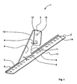
- the Fig. 1 shows a coupling element in a perspective view.
- the one-piece coupling element 1 comprises: an elongated foot flange 2 with preferably parallel longitudinal edges for connecting a in the Fig. 1 Not shown longitudinal stiffening element, in particular a stringer, as well as a bulkhead 3 for connection of a not shown Ringspants in a fuselage section of an aircraft.
- the bulkhead flange 3 includes at an angle 4 of about 90 °, in particular of 90 ° ⁇ 15 °, to a preferably substantially triangular surface element 5 or plate-shaped connecting piece.
- the surface element 5 in turn adjoins the base flange 2 at an angle 6 of approximately 90 °, in particular 90 ° ⁇ 15 °.
- the connecting piece 5 is located between the bulkhead flange 3 and the base flange 2.
- the foot flange 2 may, in particular, have a substantially rectangular geometry with two longitudinal edges extending parallel to one another, ie longitudinal edges or longitudinal sides 7, 8, the flange flange 3 or the triangular surface element 6 joining at the (rear) longitudinal side 7.
- a raised edge 9 is provided to increase the bending stiffness of the contemplatflansches 2, from the edge of which the connecting piece 5 extends.
- the width of the upstand is less than 20% of the width of theticianflansches 2.
- the upstand is preferably provided with an angle of 90 ° ⁇ 15 °.
- the surface element 5 comprises an inclined with respect to the direction of the longitudinal edge 8 of theticianflanschens 2, ie angularly extending bevel 10, with respect to the direction of the longitudinal edge 7 perpendicular to this or at an angle of 90 ° ⁇ 15 ° extending trailing edge 11 and a Angled and in particular approximately perpendicular (90 ° ⁇ 15 °) to the base flange 2 (to the median plane of the same) extending Kantline 12, where the Spantflansch 3 connects to the surface element 5 or in which the Spantflansch 3 merges into the surface element 5.
- the direction of the edge line 10 extends at an angle of 90 ° ⁇ 15 ° to the median plane of theticianflansches in its longitudinal extent.
- the crease line 12 extends approximately in the area of a center line 13 dividing the foot flange 2, ie the extension of the crease line 10 hits the plane of the foot flange in a region of 20% of the longitudinal extent of the foot flange laterally of its center line with respect to its longitudinal extent.
- the described positioning of the triangular surface element 5 or of the frame flange 3 arranged thereon on the Foot flange 2 allows a statically favorable introduction of tilting moments, which are initiated starting from the bulkhead flange 3 in the coupling element 1 and the base flange 2.
- Both the foot flange 2 and the flange 3 are provided with a plurality of holes, of which only a bore 14 is representative of the others provided with a reference numeral.
- the holes 14 are preferably grid-shaped in the base flange 2 and the bulkhead flange 3 introduced to allow a locally variable positioning of the coupling element 1 and / or a flexible connection of other components to the coupling element 1.
- the holes are used to carry out in the Fig. 1 Not shown fasteners, such as rivets, screws or the like.
- the coupling element can also be connected to the other components of the fuselage cell structure by means of thermal welding methods.
- the coupling element 1 may be formed with an aluminum alloy material, with a titanium alloy, with a stainless steel alloy, with a fiber reinforced plastic material, with Glare® or any combination of said materials.
- the material Glare® is a multi-layered layer structure in which the layers of aluminum alloy material are glued together by full-surface adhesive layers.
- fiber-reinforced plastic materials are preferably carbon fiber reinforced epoxy resins into consideration.
- the adhesive layers may be formed, for example, with a glass fiber reinforced polyester or epoxy resin.
- a coupling element 15 includes, inter alia, a base flange 16 and a flange 17, which are each formed plate-shaped.
- the bulkhead flange 17 connects at an angle 18 to an approximately triangular surface element 19.
- the foot flange 16 preferably has a rectangular shape with two parallel to one another extending Longitudinal sides 21,22 and not provided in the figure with reference numerals transverse sides, wherein in the region of the in plan view of FIG.
- the upstand is an edge region of the base flange which extends at an angle to the center plane of the remaining part or main body of the base flange, the edge region extending along a side edge and preferably with a constant width.
- the surface element or the connecting piece 19 comprises: an obliquely extending between the adjacent longitudinal edge of the contemplatflansches and a side edge of the Spantflansches inclined edge 24 and a preferably to the median plane of the solicitflansches 16 at an angle of 90 ° ⁇ 15 ° and in particular 90 ° extending trailing edge 25th and a with respect to the median plane of the researchingflansch 16, seen in the longitudinal direction, at an angle of 90 ° ⁇ 15 "and in particular 90 ° extending edge line 26.
- the inclined edge 24 may at an angle of 30 to 60 ° to the median plane of the contemplatflansch 16th
- the edge line 26 forms an "imaginary" dividing line between the flange flange 17 and the surface element 19, ie in the canted line the flange flange 17 and the surface element 19, which are integrally formed or manufactured, pass over one another down, ie the median plane of the researchingflansches 16 imaginary extension d he Kantline 26 arrives in an area of the base flange, which extends in the longitudinal direction on both sides of the center line 27 of the longitudinal extent, which so divided the base flange 16, by 20% of the longitudinal extent.
- Both the base flange 16 and the bulkhead flange 17 are provided with a plurality of holes 28.
- the coupling element 15, which is otherwise similar in construction, has an extension flange 29 with a plurality of bores 30.
- the extension flange 29 is located in the connecting region between the longer exposed edge of the connecting piece 19 and the adjoining longitudinal edge of the base flange 16 and is in one piece made with the foot flange 16 and the connecting piece 16.
- the base flange 16 preferably has a substantially L-shaped cross-sectional geometry, whereas the cross-sectional geometry of the base flange 16 in the remaining regions - apart from the minor upstand 23 - is substantially rectangular.
- the extension flange 29 is practically a one-sided "continuation" of the substantially triangular surface element 19. In the case of an at least partially adhesive bonding of the coupling element 15, the holes 18,30 can be omitted at least partially.
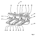
- the Fig. 3 shows a in accordance with the representation of Fig. 1 configured coupling element in the installed state in a Quemaht Scheme between two fuselage sections of a fuselage structure of an aircraft in a perspective view.
- a fuselage cell structure 31 includes, inter alia, two fuselage sections 32, 33, which are joined together in the region of a transverse seam 34.
- the fuselage cell skins 35, 36 of the two fuselage sections 32, 33 are joined together by means of a conventional transverse joint lug 37 with simultaneous creation of the transverse seam 34.
- On the fuselage cell skins 35,36 a plurality of string 38,39 are arranged or attached as a longitudinal stiffening elements.
- the Stringer 38,39 are aligned in the Area of the transverse seam 34, which also applies to the other stringer pairings in the transverse seam area, in order to ensure a largely stress-free connection by means of the coupling elements.
- cleats In the region of the transverse seam 34, a plurality of (connecting) cleats (so-called “cleats”), of which only one cleat 40 is provided with a reference number, are provided.
- a ring frame 41 or a ring frame segment is connected to the fuselage cell skins 35, 36 by means of a multiplicity of rivet elements, of which only one rivet element is provided with a reference numeral 42, representative of the remainder, via the cleats 40 and the transverse brishlet 37 running underneath.
- the stringers 38, 39 each have an inverted T-shaped cross-sectional geometry.
- the middle front stringer 38 - representative of all others - a vertical web 43, which is provided at a lower end with adjoining on both sides, each pointing opposite foot flanges 44,45.
- the right foot flange 45 of the stringer 38 is connected to a foot flange 46 of a coupling element 47.
- a bulkhead 48 of the coupling element 47 is connected to the cleat 40 and the annular frame 41.
- the structural design of the coupling element 47 is identical to that of the already in the description of the Fig. 1 explained constructive structure of the coupling element 1.
- About a substantially triangular surface element 49 tilting moments and forces of the ring washers 41 are transferred in the direction of an arrow 50 from the bulkhead 48 by means of the surface element 49 on the base flange 46 of the coupling element 47.
- the mechanical connection between the coupling element 47, the right foot flange 45 of the stringer 38 and the underlying fuselage skin 35 is preferably carried out by rivet elements, of which a rivet member 51 is representatively provided with a reference numeral for all others.
- All rivet elements 42,51 and bores for the rivet 42,51 are preferably arranged in a grid pattern to a rasterized or stepped location variable attachment of Coupling element 47 in relation to other components the fuselage tenter structure 31 to allow.
- the left foot flange 44 of the front stringer 38 is connected to the rear stringer 39 by a plurality of rivet members 53 via a simple, rectangular, or band-shaped coupling element 52 (partially concealed).
- the rivet elements 42,51,53 can be used as connecting elements, for example screws, clamps or the like.
- the fuselage structure 31 representing components (fuselage cells, stringer, Ringspant, cleats, coupling elements) is conceivable. All components of the fuselage cell structure 31 may be formed, for example, with an aluminum alloy, a titanium alloy, a stainless steel alloy, a fiber reinforced plastic material, or any combination thereof. Fiber-reinforced plastics are, in particular, carbon-fiber-reinforced epoxy resins.
- the coupling elements 1,15,47 for connecting Stringem the function of assembling the stringer
- the connection of the stringer to the fuselage skin or to the crossbar and the anti-tip device of the ring frame in the area of the crossbar between the fuselage sections is realized at the same time in an integral component , so that the number of components to be joined together are reduced in the creation of a transverse joint between two fuselage sections and equally the assembly cost.
Abstract
Description
Die Erfindung betrifft eine Anordnung von zwei Rumpfzellenhäuten eines Flugzeugs und einer Verbindungsstruktur zur Verbindung der Rumpfzellenhäute.The invention relates to an arrangement of two hull cell skins of an aircraft and a connecting structure for connecting the hull cell skins.
Die Dokumente
Moderne Flugzeuge und insbesondere Passagierflugzeuge werden heutzutage überwiegend in Sektionsbauweise hergestellt. Hierbei wird eine Vielzahl von vorgefertigten, tonnenartigen Rumpfsektionen unter Bildung von umlaufenden Quemähten zur Bildung der kompletten Flugzeugrumpfzelle zusammen gefügt. Jede Rumpfsektion umfasst eine Vielzahl von bevorzugt gleichmäßig hintereinander angeordneten Ringspanten, die mit einer umlaufenden Rumpfzellenhaut beplankt ist. Zur weiteren Aussteifung der Rumpfsektion ist zwischen jeweils zwei Ringspanten eine Vielzahl von Längsversteifungselementen mit der Rumpfzellenhaut verbunden. Die Längsversteifungselemente, bei denen es sich in der Regel um so genannte "Stringer" bzw. Stringerprofile handelt, verlaufen im Wesentlichen jeweils parallel zu einer Längsachse der Rumpfsektion und sind innenseitig über den Umfang der Rumpfsektion gleichmäßig zueinander beabstandet angeordnet. Die jeweils parallel zueinander verlaufenden Längsversteifungselemente bzw. Stringerprofile können eine Z-förmige, eine L-förmige, eine Ω-förmige oder andere Querschnittsgeometrien aufweisen. Sowohl die Rumpfzellenhaut, als auch die Ringspanten und die Längsversteifungselemente können mit einem Aluminiumlegierungsmaterial, mit einem faserverstärkten Kunststoffmaterial wie beispielsweise einem kohlefaserverstärkten Epoxidharz oder in einer so genannten Hybrid-Bauweise auch mit einer Kombination der genannten Werkstoffe gebildet sein. Zur Verbindung von zwei Rumpfsektionen unter Bildung jeweils einer umlaufenden Quernaht ist eine Vielzahl von weiteren Bauteilen erforderlich.Modern aircraft and in particular passenger aircraft are now produced mainly in section construction. In this case, a multiplicity of prefabricated, barrel-like fuselage sections are joined together to form circumferential quilting seams to form the complete aircraft fuselage cell. Each fuselage section comprises a plurality of preferably uniformly successively arranged annular frames, which is covered with a circumferential fuselage cell skin. To further stiffen the fuselage section a plurality of longitudinal stiffening elements is connected to the fuselage skin between each two annular frames. The longitudinal stiffening elements, which are usually so-called "stringer" or stringer profiles, essentially run parallel to a longitudinal axis of the fuselage section and are arranged on the inside uniformly spaced apart from each other over the circumference of the fuselage section. The respective mutually parallel longitudinal stiffening elements or stringer profiles may have a Z-shaped, an L-shaped, an Ω-shaped or other cross-sectional geometries. Both the hull cell skin, as well as the annular frames and the longitudinal stiffening elements can be formed with an aluminum alloy material, with a fiber-reinforced plastic material such as a carbon fiber reinforced epoxy resin or in a so-called hybrid construction with a combination of said materials. To connect two fuselage sections to form a circumferential cross seam, a plurality of other components is required.
Die Rumpfzellenhäute werden zunächst mit einer zumindest bereichsweise umlaufenden Querstoßlasche bevorzugt auf Stoß verbunden. Ein im Bereich der Quernaht positionierter, umlaufender Ringspant wird mit einer Vielzahl von umfangsseitig am Ringspant angeordneten Klampen, sogenannten "Cleats", mit der Querstoßlasche und mindestens einer der beiden aneinander stoßenden Rumpfzellenhäute zusammen gefügt. Auch die übrigen Ringspante außerhalb der Quemahtbereiche der Rumpfsektion können mit derartigen "Cleats" an die Rumpfzellenhaut angebunden sein. Die sich jeweils gegenüberliegenden Stringer im Bereich einer Quernaht werden mit einer Vielzahl von Stringerkupplungen verbunden. Darüber hinaus sind bei der zur Zeit angewendeten Fügetechnik zur Querstoßverbindung von zwei Rumpfsektionen eine Vielzahl von Stützelementen vorgesehen, durch die eine Abstützung des Ringspants im Quernahtbereich gegen Verkippen in Bezug zur Rumpfzellenhaut erfolgt. Alle erwähnten Bauteile müssen in Bezug zu den Strukturelementen der zu verbindenden Rumpfsektionen exakt positioniert, genauestens gebohrt und durch geeignete Verbindungselemente fest zusammen gefügt werden. Darüber hinaus sind insbesondere die Stützwinkel sowie die Stringerkupplungen für jede Querstoßverbindung zwischen zwei Rumpfsektionen in einer Stückzahl vorzuhalten und zu montieren, die in der Regel der Anzahl der in der Rumpfsektion eingebauten Stringer entspricht. Hierbei ist zusätzlich zu berücksichtigen, dass die Zahl der zur Aussteifung einer Rumpfsektion erforderlichen Stringer im Allgemeinen proportional zu ihren Querschnittsabmessungen steigt, so dass der Montageaufwand bei Rumpfzellen mit großen Querschnittsabmessungen erheblich zunimmt. Darüber hinaus müssen sämtliche Bohrlöcher aufwändigen Abdichtungs- und Korrosionsschutzprozeduren unterzogen werden.The fuselage cell skins are first connected to an at least partially circumferential cross-brace preferably on impact. An encircling annular frame positioned in the region of the transverse seam is joined together with a multitude of cleats arranged at the circumference of the ring frame, so-called "cleats", with the crossbeam flap and at least one of the two adjoining trunk cell skins. Also, the remaining ring frame outside the Quemahtbereiche the fuselage section can be connected with such "cleats" to the fuselage skin. The opposing stringer in the region of a transverse seam are connected to a plurality of stringers clutches. In addition, in the currently used joining technique for the transverse joint connection of two fuselage sections, a multiplicity of supporting elements are provided, by means of which a support of the annular frame in the transverse seam area takes place against tilting in relation to the fuselage skin. All mentioned components must be accurately positioned relative to the structural elements of the fuselage sections to be joined, accurately drilled and joined together by suitable fasteners. In addition, in particular, the support brackets and the stringer couplings for each transverse joint between two fuselage sections are to be provided and assembled in a number of pieces, which usually corresponds to the number of built-in stringer in the fuselage section. In addition, it should be noted that the number of stringers required to stiffen a fuselage section generally increases in proportion to their cross-sectional dimensions, so that the assembly effort for fuselage cells with large cross-sectional dimensions increases considerably. In addition, all wells must undergo elaborate sealing and corrosion protection procedures.
Als Verbindungselemente kommen jeweils in Abhängigkeit von den für die zu fügenden Rumpfsektionen eingesetzten Materialarten beispielsweise Nietelemente oder Schrauben in Betracht. Alternativ können thermische Fügeverfahren Anwendung finden. Faserverstärkte Kunststoffmaterialien können hingegen alternativ auch durch Klebeverbindungen gefügt werden, so dass das Einbringen von Befestigungsbohrungen entbehrlich ist.Rivets or screws may be considered as connecting elements, depending on the types of material used for the fuselage sections to be joined, for example. Alternatively, thermal joining methods can be used. By contrast, fiber-reinforced plastic materials can alternatively also be joined by adhesive bonds, so that the introduction of fastening bores is dispensable.
Aufgabe der Erfindung ist es, ein Kupplungselement für Stringer bereitzustellen, durch das die Anzahl von Kupplungselementen zur Herstellung einer Querstoßverbindung zwischen zwei zusammen zu fügenden Rumpfsektionen verringert werden kann, um den Montageaufwand bei der Montage von Rumpfsektionen zu einer kompletten Rumpfzelle für Flugzeuge zu minimieren.The object of the invention is to provide a coupling element for stringer, by which the number of coupling elements for producing a transverse joint between two fuselage sections to be joined together can be reduced in order to minimize the assembly effort in the assembly of fuselage sections to a complete fuselage cell for aircraft.
Diese Aufgabe wird durch die Anordnung mit den Merkmalen des Patentanspruchs 1 gelöst. Weitere Ausführungsformen der Erfindung sind in den Unteransprüchen angegeben.This object is achieved by the arrangement having the features of patent claim 1. Further embodiments of the invention are specified in the subclaims.
Die Verbindungsstruktur der Rumpfzellenhäute weist ein Kupplungselement mit einem Fußflansch zur Anbindung der zwei zu verbindenden Längsversteifungselemente und einem an dem Fußflansch angeordneten und zu diesem winklig verlaufenden Spantflansch zur Anbindung eines Ringspants auf. Insbesondere können die Mittelebenen des Fußflansches und des Spantflansches senkrecht zueinander verlaufen. Der Fußflansch und der Spantflansch sind insbesondere plattenförmig gebildet und können insbesondere einstückig hergestellt sein.The connecting structure of the hull cell skins has a coupling element with a foot flange for connecting the two longitudinal stiffening elements to be connected and a flange arranged on the flange and extending at an angle thereto for connecting a ring frame. In particular, the center planes of the Fußflansches and the Spantflansches can run perpendicular to each other. The foot flange and the bulkhead flange are in particular formed plate-shaped and can be made in one piece in particular.
Dadurch, dass das Kupplungselement einen Fußflansch zur Anbindung von zwei zu verbindenden Längsversteifungselementen, insbesondere zwei Stringern, und einen hierzu winklig und insbesondere im Wesentlichen senkrecht angeordneten Spantflansch zur Anbindung eines Ringspants aufweist, ist ein separater Einbau von Stützwinkeln zur Sicherung des Ringspants gegenüber seitlichen Kippbewegungen in Relation zur Rumpfzellenhaut nicht mehr erforderlich, wodurch sich der zur Herstellung einer Guerstoßverbindung zwischen zwei Rumpfsektionen unter Schaffung einer umlaufenden Quernaht erforderliche Montageaufwand signifikant reduziert. Das Kupplungselement zur Verbindung von Stringern übernimmt in einem einzigen integralen Bauteil gleichermaßen die Funktion des Zusammenfügens der Stringer, der Anbindung der Stringer an die Rumpfzellenhaut bzw. die Querstoßlasche und einer zusätzlichen Verkippsicherung der Ringspante.Due to the fact that the coupling element has a foot flange for connecting two longitudinal stiffening elements to be connected, in particular two stringers, and an angle flange and in particular substantially perpendicularly arranged flange for connecting a ring frame, a separate installation of support brackets for securing the ring frame against lateral tilting movements in Relation to the fuselage cell skin is no longer required, which significantly reduces the time required to produce a Guerstoßverbindung between two fuselage sections to create a circumferential cross seam assembly effort. The coupling element for connecting stringers takes in a single integral component alike the function of assembling the stringer, the connection of the stringer to the fuselage skin or the crossbar and an additional Verkippsicherung the ring frame.
Die mechanische Verbindung der Stringer erfolgt mittels des Kupplungselements im Wesentlichen nur noch im Fußbereich der Stringer. Nach einer vorteilhaften Ausgestaltung geht eine Längsseite des Fußflansches in ein im Wesentlichen dreieckförmiges und im Wesentlichen senkrecht, d.h. 90° ± 15°, stehendes Flächenelement oder Verbindungsstück über, an das winklig und insbesondere unter einem Winkel von 90° ± 15° der Spantflansch anschließt.The mechanical connection of the stringer takes place by means of the coupling element substantially only in the footer of the stringers. According to an advantageous embodiment, one longitudinal side of the base flange merges into a substantially triangular and substantially vertical, ie 90 ° ± 15 °, stationary surface element or connecting piece, to which the former flange adjoins at an angle and in particular at an angle of 90 ° ± 15 °.
In einer Ausführungsform der Erfindung ist der Fußflansch insbesondere als längliche Platte ausgebildet, und von einem Rand des Fußflansches aus erstreckt sich das ebenfalls plattenförmige Verbindungsstück. Die Mittelebenen des Fußflansches und des Verbindungsstücks verlaufen winklig und insbesondere in einem Winkel von 90° ± 15° zueinander. Insbesondere weist das Verbindungsstück zwischen dem Anschlussbereich des Verbindungsstücks und des Fußflansches und dem Anschlussbereich des Verbindungsstücks und des Spantflansches zwei freiliegende Kantenlinien auf, die jeweils von einer Kante des Fußflansches zu einer Kante des Spantflansches verläuft. Dabei verlaufen die freiliegenden Kantenlinien insbesondere winklig zueinander, wobei die freiliegenden Kantenlinien abschnittsweise geradlinig gebildet sind und deren Richtungen von dem Flußflansch ausgehend in einem spitzen Winkel aufeinander zu laufen. Eine oder beide freiliegenden Kantenlinien können auch kurvenförmig verlaufen, wobei sich die voranstehend bezeichneten Richtungen aus der Schwerpunktlinien der jeweiligen Kantenlinie ist.In one embodiment of the invention, the foot flange is formed in particular as an elongated plate, and from an edge of the Fußflansches also extends the plate-shaped connector. The center planes of the foot flange and the connecting piece extend at an angle and in particular at an angle of 90 ° ± 15 ° to each other. In particular, the connecting piece between the connection region of the connecting piece and the foot flange and the connection region of the connecting piece and the Spantflansches two exposed edge lines, each extending from an edge of the Fußflansches to an edge of the Spantflansches. In this case, the exposed edge lines are in particular at an angle to each other, wherein the exposed edge lines are formed in sections in a straight line and their directions starting from the Flußflansch run at an acute angle to each other. One or both of the exposed edge lines may also be curved, with the above-mentioned directions being from the centroid lines of the respective edge line.
Der Fußflansch, der Spantflansch und der zwischen diesen gelegene Verbindungsstück sind insbesondere plattenförmig gebildet und können insbesondere zusammen ein einstückig hergestelltes Bauteil bilden.The foot flange, the bulkhead flange and the connecting piece located between these are in particular plate-shaped and can in particular together form a one-piece manufactured component.
Diese Ausgestaltung ermöglicht eine einfache Herstellung des Kupplungselements, die beispielsweise für den Fall, dass das Kupplungselement mit einem Aluminiumlegierungs-Material gebildet ist, neben weiteren, insbesondere spanenden Bearbeitungsschritten, lediglich zwei Umformschritte zur Ausbildung des Fußflansches und des Spantflansches umfasst.This embodiment allows a simple production of the coupling element, which comprises, for example, in the case that the coupling element is formed with an aluminum alloy material, in addition to further, in particular machining steps, only two forming steps for forming the Fußflansches and the Spantflansches.
Darüber hinaus erlaubt die relativ geringe Anzahl der zueinander senkrecht stehenden Flächen des Kupplungselements die Fertigung mit einem faserverstärkten Kunststoffmaterial, wobei die Verstärkungsfasern bevorzugt kraftflussorientiert ausgerichtet sind.In addition, the relatively small number of mutually perpendicular surfaces of the coupling element allows the production with a fiber-reinforced Plastic material, wherein the reinforcing fibers are preferably oriented kraftflussorientiert.
Eine Weiterbildung des Kupplungselements sieht vor, dass das Flächenelement zur Ausbildung des Spantflansches im Wesentlichen mittig auf dem Fußflansch positioniert ist. Infolge dieser Anordnung ist eine statisch günstige Einleitung der aufzufangenden Kippmomente des Ringspants in den Fußflansch des Kupplungselements und damit in die Stringer sowie die darunter verlaufende Rumpfzellenhaut möglich.A development of the coupling element provides that the surface element is positioned to form the Spantflansches substantially centrally on the base flange. As a result of this arrangement, a statically favorable introduction of the overturning moments of the Ringpants in the Fußflansch of the coupling element and thus in the stringer and the underlying fuselage skin is possible.
Nach Maßgabe einer weiteren Fortbildung ist das Kupplungselement einstückig ausgestaltet und insbesondere einstückig hergestellt. Hierdurch wird die zur Herstellung einer Querstoßverbindung zwischen zwei Rumpfsektionen notwendige und vorzuhaltende Anzahl von Bauteilen maßgeblich reduziert und der Montageaufwand minimiert.In accordance with a further development, the coupling element is designed in one piece and in particular made in one piece. As a result, the necessary for the production of a transverse joint connection between two fuselage sections and vorzuhaltende number of components is significantly reduced and minimized assembly costs.
Eine weitere Fortbildung des Kupplungselements sieht vor, dass das Kupplungselement bereits herstellungsseitig mit einer Mehrzahl oder Vielzahl von exakt positionierten Bohrungen zur Einbringung von Verbindungselementen versehen ist. Die exakt vorpositioniert eingebrachten Bohrungen erleichtern die Ausrichtung des Kupplungselements im Bereich der Quernaht beim Zusammenfügen der Rumpfsektionen. Daneben können die Bohrungen zur Führung des Bohrwerkzeugs beim Einbringen der erforderlichen Befestigungsbohrungen in Strukturelemente der Rumpfsektionen beitragen. Bei den Strukturelementen handelt es sich unter anderem um die beiden bevorzugt auf Stoß zu verbindenden Rumpfzellenhäute, die Ringspante, die Klampen zur Anbindung der Ringspante an die Rumpfzellenhäute bzw. die Querstoßlaschen, die Querstoßlaschen selbst und die Stringer bzw. die Längsversteifungselemente. Gleichzeitig wird durch die Vorbohrungen die Menge der zu entsorgenden Späne und der Montageaufwand vermindert. Die Vielzahl von Bohrungen, die in der Form eines Bohrungsrasters innerhalb des Kupplungselements eingebracht sind, erlauben darüber hinaus eine in weiten Grenzen ortsvariable Befestigung des Kupplungselements bzw. eine räumlich flexible Anbindung der Strukturelemente an das Kupplungselement.A further development of the coupling element provides that the coupling element is already provided on the production side with a plurality or plurality of precisely positioned holes for the introduction of connecting elements. The precisely pre-positioned holes facilitate the alignment of the coupling element in the region of the transverse seam when joining the fuselage sections. In addition, the holes for guiding the drilling tool when introducing the required mounting holes contribute to structural elements of the fuselage sections. Among other things, the structural elements are the two fuselage cell skins, which are preferably to be jointed, the ring frame, the cleats for connecting the ring frame to the fuselage skin cells or the transverse joint straps, the transverse joint straps themselves and the stringers or the longitudinal reinforcement elements. At the same time, the amount of waste to be disposed of and the installation effort is reduced by the pre-drilling. The plurality of bores, which are introduced in the form of a bore pattern within the coupling element, moreover allow a location variable mounting of the coupling element or a spatially flexible connection of the structural elements to the coupling element.
Nach Maßgabe einer weiteren Ausgestaltung des Kupplungselements ist vorgesehen, dass das Flächenelement einen Verlängerungsflansch, insbesondere zur seitlichen Anbindung von Stringem mit einer T-förmigen oder einer Z-förmigen Querschnittsgeometrie, aufweist, wobei der Verlängerungsflansch im Wesentlichen senkrecht auf dem Fußflansch steht. Diese Ausführungsvariante des Kupplungselements erlaubt zusätzlich zur Verbindung der Stringer untereinander im Bereich des Stringerfußes und mit der Rumpfzellenhaut bzw. den Querstoßlaschen ergänzend eine Verbindung zwischen mindestens einer im Wesentlichen senkrecht zur Rumpfzellenhaut stehenden Stringerflanke mit dem Kupplungselement, wodurch die mechanische Belastbarkeit der durch das Kupplungselement verbundenen Stringer im Bedarfsfall weiter gesteigert wird.In accordance with a further embodiment of the coupling element is provided that the surface element has an extension flange, in particular for the lateral connection of stringers with a T-shaped or a Z-shaped cross-sectional geometry, wherein the extension flange is substantially perpendicular to the base flange. This embodiment of the coupling element allows in addition to the connection of the stringer with each other in the area of the Stringerfußes and with the fuselage skin or the Quererstosslaschen a connection between at least one substantially perpendicular to the fuselage cell skin Stringer flank with the coupling element, whereby the mechanical strength of the connected by the coupling element stringers if necessary, further increased.
Die Erfindung betrifft eine Kombination aus einem Längsversteifungselement, einem Ringspant und einem Kupplungselement wie beschrieben.The invention relates to a combination of a longitudinal stiffening element, a ring frame and a coupling element as described.
In der Zeichnung zeigen:
-
Fig. 1 Ein Kupplungselement für Längsversteifungselemente, insbesondere Stringer, im Bereich einer Quernaht zwischen zwei zusammen zu fügenden Rumpfsektionen, -
Fig. 2 eine Ausführungsvariante des Kupplungselements und -
Fig. 3 eine perspektivische Ansicht der ersten Ausführungsvariante im eingebauten Zustand im Bereich einer Quernaht zwischen zwei zusammen gefügten Rumpfsektionen.
-
Fig. 1 A coupling element for longitudinal stiffening elements, in particular stringer, in the region of a transverse seam between two fuselage sections to be joined together, -
Fig. 2 a variant of the coupling element and -
Fig. 3 a perspective view of the first embodiment in the installed state in the region of a transverse seam between two fuselage sections joined together.
In der Zeichnung können dieselben konstruktiven Elemente jeweils die gleiche Bezugsziffer aufweisen.In the drawing, the same constructive elements may each have the same reference numeral.
Die
Das Flächenelement 5 umfasst eine in Bezug zur Richtung des Längsrandes 8 des Fußflanschens 2 geneigte, d.h. winklig verlaufende Schrägkante 10, eine in Bezug auf die Richtung des Längsrandes 7 senkrecht oder zu dieser in einem Winkel von 90° ± 15° verlaufende Hinterkante 11 sowie eine winklig und insbesondere in etwa senkrecht (90° ± 15°) zum Fußflansch 2 (zur Mittelebene desselben) verlaufende Kantlinie 12, an der der Spantflansch 3 an das Flächenelement 5 anschließt oder in dem der Spantflansch 3 in das Flächenelement 5 übergeht. Insbesondere verläuft die Richtung der Kantenlinie 10 in einem Winkel von 90° ± 15° zur Mittelebene des Fußflansches in dessen Längserstreckung. Die Kantlinie 12 verläuft ungefähr im Bereich einer den Fußflansch 2 hälftig teilenden Mittellinie 13, d.h. die Verlängerung der Kantlinie 10 trifft auf die Ebene des Fußflansches in einem Bereich von 20% der Längserstreckung des Fußflansches seitlich dessen Mittellinie in Bezug auf dessen Längserstreckung. Die beschriebene Positionierung des dreieckförmigen Flächenelements 5 bzw. des daran angeordneten Spantflansches 3 auf dem Fußflansch 2 ermöglicht eine statisch günstige Einleitung von Kippmomenten, die ausgehend vom Spantflansch 3 in das Kupplungselement 1 bzw. den Fußflansch 2 eingeleitet werden.The
Sowohl der Fußflansch 2 als auch der Spantflansch 3 sind mit einer Vielzahl von Bohrungen versehen, von denen lediglich eine Bohrung 14 repräsentativ für die Übrigen mit einer Bezugsziffer versehen ist. Die Bohrungen 14 sind bevorzugt rasterförmig in den Fußflansch 2 sowie den Spantflansch 3 eingebracht, um eine örtlich variable Positionierung des Kupplungselements 1 und/oder eine flexible Anbindung weiterer Bauteile an das Kupplungselement 1 zu ermöglichen. Die Bohrungen dienen zur Durchführung in der
Das Kupplungselement 1 kann mit einem Aluminiumlegierungs-material, mit einer Titanlegierung, mit einer Edelstahllegierung, mit einem faserverstärkten Kunststoffmaterial, mit Glare® oder einer beliebigen Kombination der genannten Materialien gebildet sein. Bei dem Material Glare® handelt es sich um einen vielschichtigen Lagenaufbau, in dem die Lagen aus Aluminiumlegierungsmaterial jeweils durch vollflächige Klebeschichten miteinander verklebt sind. Als faserverstärkte Kunststoffmaterialien kommen bevorzugt kohlefaserverstärkte Epoxidharze in Betracht. Die Klebeschichten können beispielsweise mit einem glasfaserverstärkten Polyester- oder Epoxidharz gebildet sein.The coupling element 1 may be formed with an aluminum alloy material, with a titanium alloy, with a stainless steel alloy, with a fiber reinforced plastic material, with Glare® or any combination of said materials. The material Glare® is a multi-layered layer structure in which the layers of aluminum alloy material are glued together by full-surface adhesive layers. As fiber-reinforced plastic materials are preferably carbon fiber reinforced epoxy resins into consideration. The adhesive layers may be formed, for example, with a glass fiber reinforced polyester or epoxy resin.
Die
Im Unterschied zu der im Rahmen der
Mittels des Verlängerungsflansches 29 ist es möglich, in den
Hinsichtlich der zur Herstellung des Kupplungselements 15 einsetzbaren Materialien kann auf die im Rahmen der Beschreibung des Kupplungselements 1 weiter oben gemachten Ausführungen verwiesen werden (vgl.
Die
Eine Rumpfzellenstruktur 31 umfasst unter anderem zwei Rumpfsektionen 32,33, die im Bereich einer Quernaht 34 zusammen gefügt sind. Die Rumpfzellenhäute 35,36 der beiden Rumpfsektionen 32,33 sind mittels einer konventionellen Querstoßlasche 37 unter gleichzeitiger Schaffung der Quernaht 34 zusammen gefügt. Auf den Rumpfzellenhäuten 35,36 sind eine Vielzahl von Stringem 38,39 als Längsversteifungselemente angeordnet bzw. befestigt. Die Stringer 38,39 fluchten im Bereich der Quernaht 34, was im Übrigen auch für die weiteren Stringerpaarungen im Quernahtbereich gilt, um eine weitgehend spannungsfreie Verbindung mittels der Kupplungselemente zu gewährleisten.A
Im Bereich der Quernaht 34 sind mehrere (Verbindungs-)Klampen (so genannte "Cleats"), von denen lediglich eine Klampe 40 mit einer Bezugsziffer versehen ist vorgesehen. Ein Ringspant 41 bzw. ein Ringspantsegment ist mittels einer Vielzahl von Nietelementen, von denen lediglich ein Nietelement stellvertretend für die Übrigen mit einer Bezugsziffer 42 versehen ist, über die Klampen 40 sowie die darunter verlaufende Querstoßlasche 37 mit den Rumpfzellenhäuten 35,36 verbunden.In the region of the
Die Stringer 38,39 weisen jeweils eine umgekehrt T-förmige Querschnittsgeometrie auf. So weist beispielsweise der mittlere vordere Stringer 38 - repräsentativ für alle Übrigen - einen senkrechten Steg 43 auf, der an einem unteren Ende mit beidseitig anschließenden, jeweils entgegen gerichtet weisenden Fußflanschen 44,45 versehen ist.The
Der rechte Fußflansch 45 des Stringers 38 ist mit einem Fußflansch 46 eines Kupplungselements 47 verbunden. Ein Spantflansch 48 des Kupplungselements 47 ist mit der Klampe 40 bzw. dem Ringspant 41 verbunden. Der konstruktive Aufbau des Kupplungselements 47 ist identisch mit dem des bereits im Rahmen der Beschreibung der
Anstelle der Nietelemente 42,51,53 können als Verbindungselemente beispielsweise Schrauben, Klemmverbindungen oder dergleichen eingesetzt werden. Alternativ ist auch zumindest eine teilweise Verklebung zumindest eines Teils der vorstehend beschriebenen, die Rumpfzellenstruktur 31 darstellenden Bauteile (Rumpfzellenhäute, Stringer, Ringspant, Klampen, Kupplungselemente) denkbar. Sämtliche Bauteile der Rumpfzellenstruktur 31 können beispielsweise mit einer Aluminiumlegierung, mit einer Titanlegierung, mit einer Edelstahllegierung, einem faserverstärkten Kunststoffmaterial oder einer beliebigen Kombination hiervon gebildet sein. Als Faser verstärkte Kunststoffe kommen insbesondere kohlefaserverstärkte Epoxidharze in Betracht.Instead of the
Die alternative Ausführungsvariante des Kupplungselements 15 nach Maßgabe der
Durch die Kupplungselemente 1,15,47 zur Verbindung von Stringem wird in einem integralen Bauteil gleichzeitig die Funktion des Zusammenfügens der Stringer, der Anbindung der Stringer an die Rumpfzellenhaut bzw. an die Querstoßlasche und der Kippsicherung des Ringspants im Bereich der Querstoßlasche zwischen den Rumpfsektionen verwirklicht, so dass die Anzahl der zusammen zu fügenden Bauteile bei der Schaffung eines Querstoßes zwischen zwei Rumpfsektionen und gleichermaßen der Montageaufwand verringert werden.By the
![]()
![]()
![]()
![]()
![]()
Claims (11)
- An arrangement of two fuselage cell skins (35, 36) of an aeroplane and a connecting structure (1, 15, 47; 37, 40, 41) for purposes of connecting the fuselage cell skins (35, 36) with the formation of a transverse seam (34), the connecting structure (1, 15, 47; 37, 40, 41) having:■ a transverse splicing plate (37), which abuts onto the edge regions of the fuselage cell skins (35, 36) adjacent to one another for purposes of connecting the same along the transverse seam (34), and connects these with one another,■ an annular frame (41), or an annular frame segment, running in the direction of the butt joint, which is connected with the transverse splicing plate (37) via a multiplicity of cleats (40) on the inner face of the transverse splicing plate (37),■ a multiplicity of stringers (38, 39), running alongside one another and in each case located adjacent to one another along the butt joint, each of which stringers is connected in each case on the inner face of one of the fuselage cell skins (35, 36) with the latter,■ a coupling element (1, 15, 47), with a base flange (2), whose end sections, located opposed to one another, connect sections of stringers (38, 39) in each case facing one another and connected in each case with a fuselage cell skin (35, 36), and with a frame flange (3), which is connected with the annular frame (41), wherein the base flange (2) of the coupling element (1, 15, 47) extends between the transverse splicing plate (37) and the fuselage frame (41), or the fuselage frame segment, and transverse to the latter, so that its end sections connect two stringers (38, 39) connected in each case with different fuselage cell skins (35, 36).
- The arrangement of two fuselage cell skins (35, 36) and a connecting structure (1, 15, 47; 37, 40, 41) in accordance with Claim 1, characterised in that a longitudinal side (7, 8, 21, 22) of the base flange (2, 16, 46) of the coupling element (1, 15, 47) translates into a triangular-shaped and upright standing surface element (5, 19, 49), to which the frame flange (3, 17, 48) connects at an angle of approximately 90°.
- The arrangement of two fuselage cell skins (35, 36) and a connecting structure (1, 15, 47; 37, 40, 41) in accordance with Claim 2, characterised in that a surface element (5, 19, 49) is positioned essentially centrally on the base flange (2, 16, 46), to which surface element the frame flange (3, 17, 48) connects at an angle of approximately 90°.
- The arrangement of two fuselage cell skins (35, 36) and a connecting structure (1, 15, 47; 37, 40, 41) in accordance with one of the Claims 1 to 3, characterised in that the coupling element (1, 15, 47) is of integral design.
- The arrangement of two fuselage cell skins (35, 36) and a connecting structure (1, 15, 47; 37, 40, 41) in accordance with one of the Claims 1 to 4, characterised in that the stringers (38, 39) are in each case arranged in the region of the transverse seam (34) in an opposed manner.
- The arrangement of two fuselage cell skins (35, 36) and a connecting structure (1, 15, 47; 37, 40, 41) in accordance with one of the Claims 1 to 5, characterised in that the coupling element (1, 15, 47) is provided with a multiplicity of holes (14, 28, 30) for purposes of introducing connecting elements, in particular rivet elements (42, 51, 53), for purposes of connecting together the longitudinal stiffening elements, in particular the stringers (38, 39), and the annular frame (41).
- The arrangement of two fuselage cell skins (35, 36) and a connecting structure (1, 15, 47; 37, 40, 41) in accordance with one of the Claims 1 to 6, characterised in that an extension flange (29), in particular for purposes of sidewise connection, in particular on the side flanks, of stringers (38, 39) with a T-shaped or Z-shaped cross-sectional geometry, connects on to the surface element (19), which stands essentially upright on the base flange (16).
- The arrangement of two fuselage cell skins (35, 36) and a connecting structure (1, 15, 47; 37, 40, 41) in accordance with one of the Claims 1 to 7, characterised in that the coupling element (1, 15, 47) is formed with a fibre-reinforced plastic material and/or with a metal alloy.
- The arrangement of two fuselage cell skins (35, 36) and a connecting structure (1, 15, 47; 37, 40, 41) in accordance with Claim 8, characterised in that the metal alloy is an aluminium alloy, a titanium alloy, a stainless steel alloy, or a combination of these.
- The arrangement of two fuselage cell skins (35, 36) and a connecting structure (1, 15, 47; 37, 40, 41) in accordance with Claim 8, characterised in that the coupling element (1, 15, 47) is formed with Glare®.
- The arrangement of two fuselage cell skins (35, 36) and a connecting structure (1, 15, 47; 37, 40, 41) in accordance with one of the preceding claims, characterised in that the stringers (38, 39) have a T-shaped, Z-shaped, or Ω-shaped cross-sectional geometry.
Applications Claiming Priority (3)
| Application Number | Priority Date | Filing Date | Title |
|---|---|---|---|
| US98749707P | 2007-11-13 | 2007-11-13 | |
| DE102007054053A DE102007054053A1 (en) | 2007-11-13 | 2007-11-13 | Coupling element for connecting two longitudinal stiffening elements |
| PCT/EP2008/009595 WO2009062712A1 (en) | 2007-11-13 | 2008-11-13 | Coupling element for interconnecting two longitudinal reinforcing elements |
Publications (2)
| Publication Number | Publication Date |
|---|---|
| EP2212191A1 EP2212191A1 (en) | 2010-08-04 |
| EP2212191B1 true EP2212191B1 (en) | 2011-11-02 |
Family
ID=40560613
Family Applications (1)
| Application Number | Title | Priority Date | Filing Date |
|---|---|---|---|
| EP08849841A Not-in-force EP2212191B1 (en) | 2007-11-13 | 2008-11-13 | Fuselage sections and coupling element interconnecting them |
Country Status (10)
| Country | Link |
|---|---|
| US (1) | US8353479B2 (en) |
| EP (1) | EP2212191B1 (en) |
| JP (1) | JP2011502871A (en) |
| CN (1) | CN101883717B (en) |
| AT (1) | ATE531617T1 (en) |
| BR (1) | BRPI0820563A2 (en) |
| CA (1) | CA2705426A1 (en) |
| DE (1) | DE102007054053A1 (en) |
| RU (1) | RU2479466C2 (en) |
| WO (1) | WO2009062712A1 (en) |
Cited By (1)
| Publication number | Priority date | Publication date | Assignee | Title |
|---|---|---|---|---|
| DE102020205840B3 (en) * | 2020-05-08 | 2021-06-10 | Premium Aerotec Gmbh | Connector and method for connecting a frame and a stringer of a fuselage structure of an aircraft, fuselage structure and aircraft |
Families Citing this family (28)
| Publication number | Priority date | Publication date | Assignee | Title |
|---|---|---|---|---|
| DE102008044229A1 (en) * | 2008-12-01 | 2010-06-10 | Airbus Deutschland Gmbh | Shell component for an aircraft or spacecraft |
| TR200905857A2 (en) * | 2009-07-28 | 2009-10-21 | Anlaş Abdullah | Multi-purpose composite foot |
| FR2970463B1 (en) * | 2011-01-17 | 2013-02-15 | Airbus Operations Sas | LIGHTING DEVICE WITH IMPROVED MECHANICAL STRENGTH. |
| ES2398985B1 (en) * | 2011-03-14 | 2014-02-14 | Airbus Operations S.L. | LOAD TRANSFER DEVICES IN THE TERMINATION OF A LARGUERILLO. |
| ES2400771B1 (en) * | 2011-03-30 | 2014-02-14 | Airbus Operations S.L. | AIRCRAFT FUSELAGE WITH HIGHLY RESISTANT NOTEBOOKS. |
| FR2976916B1 (en) * | 2011-06-27 | 2013-07-26 | Airbus Operations Sas | DEVICE AND METHOD FOR ASSEMBLING TWO TRUNCONS OF AIRCRAFT FUSELAGE |
| FR2979897B1 (en) | 2011-09-13 | 2014-08-22 | Airbus Operations Sas | DEVICE FOR CONNECTING A SMOOTH TO A FRAME OF A STRUCTURE OF AN AIRCRAFT |
| EP2759467B1 (en) * | 2013-01-24 | 2016-10-19 | Airbus Operations GmbH | Aircraft frame and method of mounting two fuselage segments |
| US9879722B2 (en) * | 2013-03-11 | 2018-01-30 | Bell Helicopter Textron Inc. | Low shear modulus transition shim for elastomeric bearing bonding in torsional applications |
| EP2799220B1 (en) * | 2013-04-30 | 2020-06-17 | Airbus Operations S.L. | Composite structure for an aircraft and manufacturing method thereof |
| EP3044093B1 (en) * | 2013-09-11 | 2020-04-22 | Saab Ab | A fixture device for manufacture of aeronautical structures and a method for applying the device |
| US9656319B2 (en) * | 2013-11-13 | 2017-05-23 | The Boeing Company | Positioning system for electromagnetic riveting |
| EP2905225B1 (en) * | 2014-02-07 | 2018-10-10 | Airbus Operations GmbH | Attachment structure of an aircraft |
| CN104924672A (en) * | 2014-03-20 | 2015-09-23 | 博斯特(上海)有限公司 | Support for reinforcing safety protection board of folder gluer |
| US9527572B2 (en) * | 2014-06-26 | 2016-12-27 | The Boeing Company | Elongated structures and related assemblies |
| GB2528080A (en) * | 2014-07-08 | 2016-01-13 | Airbus Operations Ltd | Structure |
| GB2528078B (en) * | 2014-07-08 | 2020-07-29 | Airbus Operations Ltd | Structure |
| USD777014S1 (en) * | 2014-08-12 | 2017-01-24 | Servi-Sure, LLC | Integrated stiffener |
| CN104724277B (en) * | 2015-02-03 | 2017-11-24 | 新誉集团有限公司 | Light aerocraft composite thin skin entirety fast joint structure and preparation method thereof |
| US11059605B2 (en) | 2016-11-11 | 2021-07-13 | Mitsubishi Heavy Industries, Ltd. | Component manufacturing method and component manufacturing system |
| US10926858B2 (en) * | 2017-08-07 | 2021-02-23 | The Boeing Company | Pressure bulkhead system |
| CA3078907A1 (en) * | 2017-11-01 | 2019-05-09 | Nippon Steel Corporation | Overlapping bonded structure |
| DE102018202057A1 (en) | 2018-02-09 | 2019-08-14 | Premium Aerotec Gmbh | Method for manufacturing a structural component and structural component for an aircraft or spacecraft |
| US11312468B2 (en) * | 2018-08-08 | 2022-04-26 | The Boeing Company | Elongate structures, structural assemblies with elongate structures, and methods for supporting a structural load |
| US11180238B2 (en) * | 2018-11-19 | 2021-11-23 | The Boeing Company | Shear ties for aircraft wing |
| US11198497B2 (en) * | 2019-06-19 | 2021-12-14 | The Boeing Company | Splice fittings that are affixed to stringers via web-installed fasteners |
| US11724791B2 (en) * | 2019-10-08 | 2023-08-15 | The Boeing Company | Enhanced design for stringer runout terminations on composite panels |
| CN111591433B (en) * | 2019-11-12 | 2021-10-22 | 中国科学院兰州化学物理研究所 | Flexible skin and preparation method and application thereof |
Family Cites Families (15)
| Publication number | Priority date | Publication date | Assignee | Title |
|---|---|---|---|---|
| US2382358A (en) * | 1944-02-03 | 1945-08-14 | Budd Edward G Mfg Co | Stressed skin airfoil joint |
| US3071217A (en) * | 1960-01-15 | 1963-01-01 | Avro Aircraft Ltd | Vibration damping in sheet metal structures |
| US3600016A (en) * | 1970-03-23 | 1971-08-17 | Boeing Co | Frame stringer tie |
| US3920206A (en) * | 1974-08-05 | 1975-11-18 | Us Air Force | Non-penetrating rib-to-surface structural clip connector assembly |
| CA1177459A (en) | 1980-04-21 | 1984-11-06 | Lear Fan Corp. | Composite structure for joining intersecting structural members of an airframe and the like |
| FR2489779A1 (en) | 1980-09-09 | 1982-03-12 | Aerospatiale | FUSELAGE STRUCTURE FOR AN AIRCRAFT RESISTANT TO THE LONGITUDINAL BREAKAGE OF THE EXTERIOR COATING |
| US5518208A (en) * | 1993-12-28 | 1996-05-21 | The Boeing Company | Optimum aircraft body frame to body skin shear tie installation pattern for body skin/stringer circumferential splices |
| US6073405A (en) * | 1995-12-22 | 2000-06-13 | Icf Kaiser Engineers, Inc. | Fitting for effecting bolted connection between a beam and a column in a steel frame structure |
| US6766984B1 (en) * | 1998-07-16 | 2004-07-27 | Icom Engineering Corporation | Stiffeners for aircraft structural panels |
| DE10007995C2 (en) * | 2000-02-22 | 2002-03-07 | Airbus Gmbh | Structural component, in particular for an aircraft and method for producing a structural component |
| RU2190556C2 (en) * | 2000-08-25 | 2002-10-10 | Открытое акционерное общество Авиационный научно-технический комплекс им. А.Н.Туполева | Primary structure compartment |
| GB0219451D0 (en) * | 2002-08-21 | 2002-09-25 | Bae Systems Plc | A bracket |
| US8156711B2 (en) * | 2003-02-24 | 2012-04-17 | Bell Helicopter Textron Inc. | Contact stiffeners for structural skins |
| FR2906008B1 (en) * | 2006-09-15 | 2008-11-07 | Airbus France Sa | SMOOTH CHEST AND ORBITAL JUNCTION DEVICE |
| FR2922516B1 (en) * | 2007-10-18 | 2010-04-16 | Airbus France | LIGHTING OF OMEGA STIFFENERS AT THE CIRCUMFERENTIAL JUNCTION OF AN AIRCRAFT FUSELAGE |
-
2007
- 2007-11-13 DE DE102007054053A patent/DE102007054053A1/en not_active Ceased
-
2008
- 2008-11-13 CA CA2705426A patent/CA2705426A1/en not_active Abandoned
- 2008-11-13 US US12/742,206 patent/US8353479B2/en not_active Expired - Fee Related
- 2008-11-13 EP EP08849841A patent/EP2212191B1/en not_active Not-in-force
- 2008-11-13 WO PCT/EP2008/009595 patent/WO2009062712A1/en active Application Filing
- 2008-11-13 JP JP2010533495A patent/JP2011502871A/en not_active Withdrawn
- 2008-11-13 AT AT08849841T patent/ATE531617T1/en active
- 2008-11-13 CN CN200880115949.9A patent/CN101883717B/en not_active Expired - Fee Related
- 2008-11-13 BR BRPI0820563A patent/BRPI0820563A2/en not_active IP Right Cessation
- 2008-11-13 RU RU2010123690/11A patent/RU2479466C2/en not_active IP Right Cessation
Cited By (3)
| Publication number | Priority date | Publication date | Assignee | Title |
|---|---|---|---|---|
| DE102020205840B3 (en) * | 2020-05-08 | 2021-06-10 | Premium Aerotec Gmbh | Connector and method for connecting a frame and a stringer of a fuselage structure of an aircraft, fuselage structure and aircraft |
| EP3907129A1 (en) | 2020-05-08 | 2021-11-10 | Premium AEROTEC GmbH | Connector and method for connecting a frame and a stringer of a fuselage structure of an aircraft, fuselage structure and aircraft |
| US11643181B2 (en) | 2020-05-08 | 2023-05-09 | Premium Aerotec Gmbh | Connector and method for connecting a frame and a stringer of a fuselage structure of an aircraft, fuselage structure and aircraft |
Also Published As
| Publication number | Publication date |
|---|---|
| CN101883717B (en) | 2014-08-06 |
| WO2009062712A1 (en) | 2009-05-22 |
| CN101883717A (en) | 2010-11-10 |
| WO2009062712A4 (en) | 2009-07-09 |
| RU2010123690A (en) | 2011-12-20 |
| BRPI0820563A2 (en) | 2017-05-23 |
| JP2011502871A (en) | 2011-01-27 |
| CA2705426A1 (en) | 2009-05-22 |
| ATE531617T1 (en) | 2011-11-15 |
| EP2212191A1 (en) | 2010-08-04 |
| DE102007054053A1 (en) | 2009-05-20 |
| RU2479466C2 (en) | 2013-04-20 |
| US20110001010A1 (en) | 2011-01-06 |
| US8353479B2 (en) | 2013-01-15 |
Similar Documents
| Publication | Publication Date | Title |
|---|---|---|
| EP2212191B1 (en) | Fuselage sections and coupling element interconnecting them | |
| DE102007029500B4 (en) | Method for coupling stiffening profile elements and structural component | |
| EP2225153B1 (en) | Coupling device for joining fuselage sections, combination of a coupling device and at least one fuselage section, and method for producing said coupling device | |
| DE102009013585B4 (en) | Fuselage cell structure for a hybrid aircraft | |
| DE102008013365B4 (en) | Transverse joint between two fuselage sections | |
| EP2331318B1 (en) | Fiber composite component for energy absorption in the event of a crash for an aircraft or spacecraft, fuselage structural section of an aircraft or spacecraft, and aircraft or spacecraft | |
| DE102006026167B3 (en) | Lightweight structural panel | |
| EP1646555A1 (en) | Cargo deck and a method for assembling said deck | |
| EP2454150B1 (en) | Shell segment for producing a fuselage cell section for a fuselage cell of an airplane | |
| WO2009146958A1 (en) | Composite and structure, particularly in the aerospace sector | |
| DE60218664T2 (en) | DEVICE FOR SPREADING A BOWL IN AN AIRPLANE PUMP | |
| EP2170696B1 (en) | Profile comprising at least one hollow profile section | |
| DE102008006834A1 (en) | Connecting arrangement for connecting two stiffening elements of different cross-sectional profile for an aircraft or spacecraft, and a shell component | |
| DE112010005382T5 (en) | Wall section for a wind turbine tower | |
| EP1393893A1 (en) | Lightweight material structure made of metal composite material | |
| DE102009056998B4 (en) | Stiffening structure for fabrics and aircraft | |
| DE102007018183A1 (en) | Frame construction for large sized vehicle e.g. omni bus, has four profile bars connected with one another in area of associated joint under intervention of node element, where bars are placed at distance from one another | |
| DE102009056994B4 (en) | Butt joint between fuselage sections and procedures | |
| DE102006026918B4 (en) | hull structure | |
| DE102007052098A1 (en) | Crossbar for creating a fuselage cell and method for connecting two in particular wound CFRP fuselage sections | |
| DE102022112587B3 (en) | Structural sheet metal profile for a support structure, support structure and method of manufacture, boat hull and catamaran | |
| DE102022002491B3 (en) | Structural sheet metal profile, support structure and method of manufacture, boat hull and catamaran | |
| DE102009007730B4 (en) | structural component | |
| DE102015208024A1 (en) | Fuselage section and transverse joint of two fuselage sections of an aircraft or spacecraft | |
| WO2009047665A1 (en) | Reinforcing profile for aircraft structures |
Legal Events
| Date | Code | Title | Description |
|---|---|---|---|
| PUAI | Public reference made under article 153(3) epc to a published international application that has entered the european phase |
Free format text: ORIGINAL CODE: 0009012 |
|
| 17P | Request for examination filed |
Effective date: 20100614 |
|
| AK | Designated contracting states |
Kind code of ref document: A1 Designated state(s): AT BE BG CH CY CZ DE DK EE ES FI FR GB GR HR HU IE IS IT LI LT LU LV MC MT NL NO PL PT RO SE SI SK TR |
|
| AX | Request for extension of the european patent |
Extension state: AL BA MK RS |
|
| DAX | Request for extension of the european patent (deleted) | ||
| GRAP | Despatch of communication of intention to grant a patent |
Free format text: ORIGINAL CODE: EPIDOSNIGR1 |
|
| RTI1 | Title (correction) |
Free format text: FUSELAGE SECTIONS AND COUPLING ELEMENT INTERCONNECTING THEM |
|
| GRAS | Grant fee paid |
Free format text: ORIGINAL CODE: EPIDOSNIGR3 |
|
| GRAA | (expected) grant |
Free format text: ORIGINAL CODE: 0009210 |
|
| AK | Designated contracting states |
Kind code of ref document: B1 Designated state(s): AT BE BG CH CY CZ DE DK EE ES FI FR GB GR HR HU IE IS IT LI LT LU LV MC MT NL NO PL PT RO SE SI SK TR |
|
| REG | Reference to a national code |
Ref country code: GB Ref legal event code: FG4D Free format text: NOT ENGLISH |
|
| REG | Reference to a national code |
Ref country code: CH Ref legal event code: EP |
|
| REG | Reference to a national code |
Ref country code: IE Ref legal event code: FG4D |
|
| REG | Reference to a national code |
Ref country code: DE Ref legal event code: R096 Ref document number: 502008005479 Country of ref document: DE Effective date: 20120112 |
|
| REG | Reference to a national code |
Ref country code: NL Ref legal event code: VDEP Effective date: 20111102 |
|
| LTIE | Lt: invalidation of european patent or patent extension |
Effective date: 20111102 |
|
| PG25 | Lapsed in a contracting state [announced via postgrant information from national office to epo] |
Ref country code: LT Free format text: LAPSE BECAUSE OF FAILURE TO SUBMIT A TRANSLATION OF THE DESCRIPTION OR TO PAY THE FEE WITHIN THE PRESCRIBED TIME-LIMIT Effective date: 20111102 Ref country code: IS Free format text: LAPSE BECAUSE OF FAILURE TO SUBMIT A TRANSLATION OF THE DESCRIPTION OR TO PAY THE FEE WITHIN THE PRESCRIBED TIME-LIMIT Effective date: 20120302 Ref country code: NO Free format text: LAPSE BECAUSE OF FAILURE TO SUBMIT A TRANSLATION OF THE DESCRIPTION OR TO PAY THE FEE WITHIN THE PRESCRIBED TIME-LIMIT Effective date: 20120202 |
|
| BERE | Be: lapsed |
Owner name: AIRBUS OPERATIONS G.M.B.H. Effective date: 20111130 |
|
| PG25 | Lapsed in a contracting state [announced via postgrant information from national office to epo] |
Ref country code: GR Free format text: LAPSE BECAUSE OF FAILURE TO SUBMIT A TRANSLATION OF THE DESCRIPTION OR TO PAY THE FEE WITHIN THE PRESCRIBED TIME-LIMIT Effective date: 20120203 Ref country code: PL Free format text: LAPSE BECAUSE OF FAILURE TO SUBMIT A TRANSLATION OF THE DESCRIPTION OR TO PAY THE FEE WITHIN THE PRESCRIBED TIME-LIMIT Effective date: 20111102 Ref country code: LV Free format text: LAPSE BECAUSE OF FAILURE TO SUBMIT A TRANSLATION OF THE DESCRIPTION OR TO PAY THE FEE WITHIN THE PRESCRIBED TIME-LIMIT Effective date: 20111102 Ref country code: HR Free format text: LAPSE BECAUSE OF FAILURE TO SUBMIT A TRANSLATION OF THE DESCRIPTION OR TO PAY THE FEE WITHIN THE PRESCRIBED TIME-LIMIT Effective date: 20111102 Ref country code: SI Free format text: LAPSE BECAUSE OF FAILURE TO SUBMIT A TRANSLATION OF THE DESCRIPTION OR TO PAY THE FEE WITHIN THE PRESCRIBED TIME-LIMIT Effective date: 20111102 Ref country code: SE Free format text: LAPSE BECAUSE OF FAILURE TO SUBMIT A TRANSLATION OF THE DESCRIPTION OR TO PAY THE FEE WITHIN THE PRESCRIBED TIME-LIMIT Effective date: 20111102 Ref country code: NL Free format text: LAPSE BECAUSE OF FAILURE TO SUBMIT A TRANSLATION OF THE DESCRIPTION OR TO PAY THE FEE WITHIN THE PRESCRIBED TIME-LIMIT Effective date: 20111102 Ref country code: PT Free format text: LAPSE BECAUSE OF FAILURE TO SUBMIT A TRANSLATION OF THE DESCRIPTION OR TO PAY THE FEE WITHIN THE PRESCRIBED TIME-LIMIT Effective date: 20120302 |
|
| REG | Reference to a national code |
Ref country code: DE Ref legal event code: R119 Ref document number: 502008005479 Country of ref document: DE Ref country code: DE Ref legal event code: R409 Ref document number: 502008005479 Country of ref document: DE |
|
| REG | Reference to a national code |
Ref country code: IE Ref legal event code: FD4D |
|
| PG25 | Lapsed in a contracting state [announced via postgrant information from national office to epo] |
Ref country code: MC Free format text: LAPSE BECAUSE OF NON-PAYMENT OF DUE FEES Effective date: 20111130 Ref country code: CY Free format text: LAPSE BECAUSE OF FAILURE TO SUBMIT A TRANSLATION OF THE DESCRIPTION OR TO PAY THE FEE WITHIN THE PRESCRIBED TIME-LIMIT Effective date: 20111102 |
|
| PG25 | Lapsed in a contracting state [announced via postgrant information from national office to epo] |
Ref country code: DK Free format text: LAPSE BECAUSE OF FAILURE TO SUBMIT A TRANSLATION OF THE DESCRIPTION OR TO PAY THE FEE WITHIN THE PRESCRIBED TIME-LIMIT Effective date: 20111102 Ref country code: CZ Free format text: LAPSE BECAUSE OF FAILURE TO SUBMIT A TRANSLATION OF THE DESCRIPTION OR TO PAY THE FEE WITHIN THE PRESCRIBED TIME-LIMIT Effective date: 20111102 Ref country code: SK Free format text: LAPSE BECAUSE OF FAILURE TO SUBMIT A TRANSLATION OF THE DESCRIPTION OR TO PAY THE FEE WITHIN THE PRESCRIBED TIME-LIMIT Effective date: 20111102 Ref country code: BG Free format text: LAPSE BECAUSE OF FAILURE TO SUBMIT A TRANSLATION OF THE DESCRIPTION OR TO PAY THE FEE WITHIN THE PRESCRIBED TIME-LIMIT Effective date: 20120202 Ref country code: IE Free format text: LAPSE BECAUSE OF FAILURE TO SUBMIT A TRANSLATION OF THE DESCRIPTION OR TO PAY THE FEE WITHIN THE PRESCRIBED TIME-LIMIT Effective date: 20111102 Ref country code: EE Free format text: LAPSE BECAUSE OF FAILURE TO SUBMIT A TRANSLATION OF THE DESCRIPTION OR TO PAY THE FEE WITHIN THE PRESCRIBED TIME-LIMIT Effective date: 20111102 |
|
| REG | Reference to a national code |
Ref country code: DE Ref legal event code: R409 Ref document number: 502008005479 Country of ref document: DE |
|
| PG25 | Lapsed in a contracting state [announced via postgrant information from national office to epo] |
Ref country code: RO Free format text: LAPSE BECAUSE OF FAILURE TO SUBMIT A TRANSLATION OF THE DESCRIPTION OR TO PAY THE FEE WITHIN THE PRESCRIBED TIME-LIMIT Effective date: 20111102 Ref country code: IT Free format text: LAPSE BECAUSE OF FAILURE TO SUBMIT A TRANSLATION OF THE DESCRIPTION OR TO PAY THE FEE WITHIN THE PRESCRIBED TIME-LIMIT Effective date: 20111102 Ref country code: BE Free format text: LAPSE BECAUSE OF NON-PAYMENT OF DUE FEES Effective date: 20111130 |
|
| PLBE | No opposition filed within time limit |
Free format text: ORIGINAL CODE: 0009261 |
|
| STAA | Information on the status of an ep patent application or granted ep patent |
Free format text: STATUS: NO OPPOSITION FILED WITHIN TIME LIMIT |
|
| 26N | No opposition filed |
Effective date: 20120803 |
|
| PG25 | Lapsed in a contracting state [announced via postgrant information from national office to epo] |
Ref country code: MT Free format text: LAPSE BECAUSE OF FAILURE TO SUBMIT A TRANSLATION OF THE DESCRIPTION OR TO PAY THE FEE WITHIN THE PRESCRIBED TIME-LIMIT Effective date: 20111102 |
|
| REG | Reference to a national code |
Ref country code: DE Ref legal event code: R097 Ref document number: 502008005479 Country of ref document: DE Effective date: 20120803 |
|
| PG25 | Lapsed in a contracting state [announced via postgrant information from national office to epo] |
Ref country code: ES Free format text: LAPSE BECAUSE OF FAILURE TO SUBMIT A TRANSLATION OF THE DESCRIPTION OR TO PAY THE FEE WITHIN THE PRESCRIBED TIME-LIMIT Effective date: 20120213 |
|
| PG25 | Lapsed in a contracting state [announced via postgrant information from national office to epo] |
Ref country code: LU Free format text: LAPSE BECAUSE OF NON-PAYMENT OF DUE FEES Effective date: 20111113 |
|
| PG25 | Lapsed in a contracting state [announced via postgrant information from national office to epo] |
Ref country code: FI Free format text: LAPSE BECAUSE OF FAILURE TO SUBMIT A TRANSLATION OF THE DESCRIPTION OR TO PAY THE FEE WITHIN THE PRESCRIBED TIME-LIMIT Effective date: 20111102 |
|
| REG | Reference to a national code |
Ref country code: CH Ref legal event code: PL |
|
| PG25 | Lapsed in a contracting state [announced via postgrant information from national office to epo] |
Ref country code: CH Free format text: LAPSE BECAUSE OF NON-PAYMENT OF DUE FEES Effective date: 20121130 Ref country code: LI Free format text: LAPSE BECAUSE OF NON-PAYMENT OF DUE FEES Effective date: 20121130 |
|
| REG | Reference to a national code |
Ref country code: DE Ref legal event code: R082 Ref document number: 502008005479 Country of ref document: DE Representative=s name: UEXKUELL & STOLBERG, DE Ref country code: DE Ref legal event code: R082 Ref document number: 502008005479 Country of ref document: DE Representative=s name: BIRD & BIRD LLP, DE |
|
| PG25 | Lapsed in a contracting state [announced via postgrant information from national office to epo] |
Ref country code: TR Free format text: LAPSE BECAUSE OF FAILURE TO SUBMIT A TRANSLATION OF THE DESCRIPTION OR TO PAY THE FEE WITHIN THE PRESCRIBED TIME-LIMIT Effective date: 20111102 |
|
| PG25 | Lapsed in a contracting state [announced via postgrant information from national office to epo] |
Ref country code: HU Free format text: LAPSE BECAUSE OF FAILURE TO SUBMIT A TRANSLATION OF THE DESCRIPTION OR TO PAY THE FEE WITHIN THE PRESCRIBED TIME-LIMIT Effective date: 20111102 |
|
| REG | Reference to a national code |
Ref country code: AT Ref legal event code: MM01 Ref document number: 531617 Country of ref document: AT Kind code of ref document: T Effective date: 20131113 |
|
| PG25 | Lapsed in a contracting state [announced via postgrant information from national office to epo] |
Ref country code: AT Free format text: LAPSE BECAUSE OF NON-PAYMENT OF DUE FEES Effective date: 20131113 |
|
| REG | Reference to a national code |
Ref country code: FR Ref legal event code: PLFP Year of fee payment: 8 |
|
| REG | Reference to a national code |
Ref country code: DE Ref legal event code: R082 Ref document number: 502008005479 Country of ref document: DE Representative=s name: BIRD & BIRD LLP, DE |
|
| REG | Reference to a national code |
Ref country code: FR Ref legal event code: PLFP Year of fee payment: 9 |
|
| PGFP | Annual fee paid to national office [announced via postgrant information from national office to epo] |
Ref country code: FR Payment date: 20161118 Year of fee payment: 9 Ref country code: GB Payment date: 20161122 Year of fee payment: 9 |
|
| GBPC | Gb: european patent ceased through non-payment of renewal fee |
Effective date: 20171113 |
|
| REG | Reference to a national code |
Ref country code: FR Ref legal event code: ST Effective date: 20180731 |
|
| PG25 | Lapsed in a contracting state [announced via postgrant information from national office to epo] |
Ref country code: FR Free format text: LAPSE BECAUSE OF NON-PAYMENT OF DUE FEES Effective date: 20171130 |
|
| PG25 | Lapsed in a contracting state [announced via postgrant information from national office to epo] |
Ref country code: GB Free format text: LAPSE BECAUSE OF NON-PAYMENT OF DUE FEES Effective date: 20171113 |
|
| PGFP | Annual fee paid to national office [announced via postgrant information from national office to epo] |
Ref country code: DE Payment date: 20191121 Year of fee payment: 12 |
|
| REG | Reference to a national code |
Ref country code: DE Ref legal event code: R119 Ref document number: 502008005479 Country of ref document: DE |
|
| PG25 | Lapsed in a contracting state [announced via postgrant information from national office to epo] |
Ref country code: DE Free format text: LAPSE BECAUSE OF NON-PAYMENT OF DUE FEES Effective date: 20210601 |