EP2212155B2 - Mounting construction for an outside mirror unit - Google Patents
Mounting construction for an outside mirror unit Download PDFInfo
- Publication number
- EP2212155B2 EP2212155B2 EP08850822.1A EP08850822A EP2212155B2 EP 2212155 B2 EP2212155 B2 EP 2212155B2 EP 08850822 A EP08850822 A EP 08850822A EP 2212155 B2 EP2212155 B2 EP 2212155B2
- Authority
- EP
- European Patent Office
- Prior art keywords
- adjustment instrument
- carrier
- mounting
- mirror
- construction according
- Prior art date
- Legal status (The legal status is an assumption and is not a legal conclusion. Google has not performed a legal analysis and makes no representation as to the accuracy of the status listed.)
- Active
Links
Images


Classifications
-
- B—PERFORMING OPERATIONS; TRANSPORTING
- B60—VEHICLES IN GENERAL
- B60R—VEHICLES, VEHICLE FITTINGS, OR VEHICLE PARTS, NOT OTHERWISE PROVIDED FOR
- B60R1/00—Optical viewing arrangements; Real-time viewing arrangements for drivers or passengers using optical image capturing systems, e.g. cameras or video systems specially adapted for use in or on vehicles
- B60R1/02—Rear-view mirror arrangements
- B60R1/06—Rear-view mirror arrangements mounted on vehicle exterior
- B60R1/062—Rear-view mirror arrangements mounted on vehicle exterior with remote control for adjusting position
- B60R1/07—Rear-view mirror arrangements mounted on vehicle exterior with remote control for adjusting position by electrically powered actuators
- B60R1/072—Rear-view mirror arrangements mounted on vehicle exterior with remote control for adjusting position by electrically powered actuators for adjusting the mirror relative to its housing
Definitions
- the invention relates to a mounting construction for mounting an adjustment instrument to a carrier for an outside mirror unit.
- motor vehicles are provided with outside mirrors. Often, the reflecting part of these mirrors can be adjusted from inside the vehicle to optimize the view of the driver. To that end, an adjustment instrument is placed between the reflecting surface and a carrier included in the outside mirror. The reflecting surface can then, typically driven electrically, tilt about a horizontal or a vertical axis.
- the carrier is normally encased by a mirror cap, for esthetic and aerodynamic reasons.
- the adjustment instrument is normally connected to the carrier through screws. This screw connection has as a disadvantage that it takes some time for it to be effected. It is therefore economically useful to obviate the application of screws here, also because the screws themselves cost money. In addition, when applying screws, much can go wrong.
- a screw connection may fail because the screw is applied wide of the screw hole.
- a screw may be tightened insufficiently, so that the adjustment instrument with the reflecting surface attached thereto is not rigidly secured to the carrier and may vibrate.
- a screw may eventually come loose in the mirror cap. The outside mirror may then start to rattle, which is experienced as a nuisance.
- WO2007/128468 A1 discloses a mounting device for a position regulating mechanisms for external rear-view mirrors for motor vehicles, applicable to external rear-view mirrors of the type which are comprised of a support, attached to which is a housing which encases or is part of the aforementioned position regulating mechanism, to which a mirror support plate is affixed.
- the device can be operated manually or electrically, from the interior of the vehicle.
- the support comprises elastic pressure exertion means comprising a portion of the base arranged on the support and are provided with at least one tab.
- the pressure exertion means are intended to withstand the pressure of the housing of the regulating mechanism when the latter is attached to the support by means of the fixing means, said pressure means being elastically distorted in such a way that they exert an effort force on the housing against the fixing means.
- DE 20 2008 016 636 U1 discloses a mirror assembly having a mirror housing, a mirror glass and a mirror glass adjustment means for movement of the mirror glass relative to the mirror housing.
- DE 3023734 A1 discloses a mirror, contained in a rigid casing fixed to a vehicle bodywork.
- the casing holds a mirror carrier and an enclosed chassis containing the motors and their linkage to the mirror carrier.
- the chassis has a cup-shaped opening into which a spherical boss attached to the mirror carrier fits.
- a spring assembly holds the boss in contact with its seat and provides sufficient friction to hold the mirror securely in position against vehicle vibration.
- Two mirrors and drives move the mirror carrier in two mutually perpendicular axes.
- the invention contemplates a mounting construction of the type mentioned in the opening paragraph by which the disadvantages mentioned are prevented.
- the mounting construction for mounting an adjustment instrument to a carrier for an outside mirror unit comprises the features of claim 1.
- the carrier is surrounded by a mirror cap and the adjustment instrument is provided with a reflecting surface, while the edge of the reflecting surface is so closely adjacent to the inside of the mirror cap that after placement of the reflecting surface on the adjustment instrument already mounted in the manner as described in the preceding paragraph, it is not possible anymore to displace the adjustment instrument back to its first position, because this is prevented by the cooperation between the outer edge of the reflecting surface and the inner edge of the mirror cap.
- the mirror may hence be circumferentially enclosed by the mirror cap.
- the axial confinement can be obtained by at least two projections, one on the carrier and one on the adjustment instrument, which cooperate with each other in the second position, such that they prevent an axial displacement of the adjustment instrument along axis A.
- the work to displace the adjustment instrument from the second position to the first position is greater than the work in opposite direction.
- a plug element fitted to the adjustment instrument to supply the driving mechanisms present in the adjustment instrument with energy is locked such that the plug element cannot be uncoupled anymore if the adjustment instrument is in the second position.
- the adjustment instrument is mounted on the carrier.
- uncoupling of the plug element is prevented.
- These snap hooks are fragile and sometimes break off, so that uncoupling of the plug element sometimes cannot be prevented. It is therefore advantageous to arrange for this locking to come about differently, for instance by combining the locking with the displacement from the first position to the second position.
- the invention also relates to an outside mirror unit comprising a mirror cap which surrounds a carrier, an adjustment instrument and a mounting construction for mounting the adjustment instrument to the carrier, while the adjustment instrument is provided with a mirror.
- Fig. 1 shows the adjustment instrument 1 placed on the carrier 2.
- the displacement is a rotation about an axis A.
- the rotation axis A extends substantially transversely to the plane of the carrier 2 and forms the central axis of a substantially circular adjustment instrument 1.
- the adjustment instrument 1 is provided with a mounting part 3, here designed as a projection.
- the carrier 2 is likewise provided with a mounting part 4, here designed as a projection.
- the two projections 3 and 4 can cooperate with each other to mount the adjustment instrument 1 to the carrier 2.
- the mounting parts guide the adjustment instrument 1 relative to the carrier 2 from a first position to a second position in a direction along the carrier 2. In the second position, the mounting parts 3, 4 cooperate with each other to fix movement of the adjustment instrument relative to the carrier in a direction transverse to the carrier 2. In the first position the adjustment instrument 1 and the carrier 2 are clear of each other.
- Fig. 1 also shows the projection 3 with top surface 31 on the adjustment instrument 1.
- the adjustment instrument 1 is provided with three projections 3 which are situated at a uniform distance and at an equal radius from the intersection of the axis A and the carrier 2, but this is not requisite. It is also conceivable that the projections 3 are situated at different radii from the intersection of axis A and the carrier 2.
- the top surface 31 of projection 3 cooperates with the bottom surface 41 of projection 4 on carrier 2, as will be elucidated with the help of Figs. 5 and 6 .
- Fig. 2 shows the adjustment instrument 1 on carrier 2 in the second position.
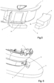
- Fig. 3 shows an outside mirror unit 20 with mirror cap 5 having therein a reflecting surface 6 mounted on the adjustment instrument 1, not shown.
- the reflecting surface 6 is designed as a mirror.
- the detailed view in Fig. 4 shows that the outer edge 61 of the mirroring surface 6 is closely adjacent to the inner edge 51 of the mirror cap 5.
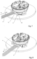
- Fig. 5 shows projection 3 of the adjustment instrument 1 and projection 4 of the carrier 2 in the first position.
- Fig. 6 it can be seen that upon rotation of the adjustment instrument 1 to the second position the top surface 31 of projection 3 slides under the bottom surface 41 of projection 4 and thereby prevents a displacement of the adjustment instrument 1 relative to the carrier 2 along axis A.
- the mounting parts projection 3 and projection 4 apply a bias to each other, so that play is reduced, which can prevent possible rattling.
- This bias may be effected by a spring, but also for instance by elastic deformation of the projection material.
- Fig. 7 shows the adjustment instrument 1 in the first position with a plug element 7 mounted for the power supply.
- this is a plug having three current carriers 9, but there may be more, for instance if the adjustment instrument 1 is provided with a memory function for the position of the reflecting surface 6.
- the plug element 7 Prior to mounting of the adjustment instrument 1, the plug element 7 is fitted thereto in the direction of arrow B, whereby the power supply is effected in a manner known to those skilled in the art.
- a projection 8 Provided on the carrier 2 is a projection 8.
- the surface 81 of projection 8 facing the plug element 7 cooperates with surface 71 of the plug element 7, more specifically in such a manner that the plug element 7 is locked in the direction C, as can be seen in Fig. 8 .
Landscapes
- Engineering & Computer Science (AREA)
- Multimedia (AREA)
- Mechanical Engineering (AREA)
- Rear-View Mirror Devices That Are Mounted On The Exterior Of The Vehicle (AREA)
Description
- The invention relates to a mounting construction for mounting an adjustment instrument to a carrier for an outside mirror unit.
- As is known, motor vehicles are provided with outside mirrors. Often, the reflecting part of these mirrors can be adjusted from inside the vehicle to optimize the view of the driver. To that end, an adjustment instrument is placed between the reflecting surface and a carrier included in the outside mirror. The reflecting surface can then, typically driven electrically, tilt about a horizontal or a vertical axis. The carrier is normally encased by a mirror cap, for esthetic and aerodynamic reasons. The adjustment instrument is normally connected to the carrier through screws. This screw connection has as a disadvantage that it takes some time for it to be effected. It is therefore economically useful to obviate the application of screws here, also because the screws themselves cost money. In addition, when applying screws, much can go wrong. Thus, a screw connection may fail because the screw is applied wide of the screw hole. A screw may be tightened insufficiently, so that the adjustment instrument with the reflecting surface attached thereto is not rigidly secured to the carrier and may vibrate. Also, a screw may eventually come loose in the mirror cap. The outside mirror may then start to rattle, which is experienced as a nuisance.
-
DE 29 07 433 B andDE 103 58 263 A1 both disclose a mounting construction for mounting an adjustment instrument to a carrier for an outside mirror unit. -
WO2007/128468 A1 discloses a mounting device for a position regulating mechanisms for external rear-view mirrors for motor vehicles, applicable to external rear-view mirrors of the type which are comprised of a support, attached to which is a housing which encases or is part of the aforementioned position regulating mechanism, to which a mirror support plate is affixed. The device can be operated manually or electrically, from the interior of the vehicle. The support comprises elastic pressure exertion means comprising a portion of the base arranged on the support and are provided with at least one tab. The pressure exertion means are intended to withstand the pressure of the housing of the regulating mechanism when the latter is attached to the support by means of the fixing means, said pressure means being elastically distorted in such a way that they exert an effort force on the housing against the fixing means. -
DE 20 2008 016 636 U1 discloses a mirror assembly having a mirror housing, a mirror glass and a mirror glass adjustment means for movement of the mirror glass relative to the mirror housing. -
DE 3023734 A1 discloses a mirror, contained in a rigid casing fixed to a vehicle bodywork. The casing holds a mirror carrier and an enclosed chassis containing the motors and their linkage to the mirror carrier. The chassis has a cup-shaped opening into which a spherical boss attached to the mirror carrier fits. A spring assembly holds the boss in contact with its seat and provides sufficient friction to hold the mirror securely in position against vehicle vibration. Two mirrors and drives move the mirror carrier in two mutually perpendicular axes. - The invention contemplates a mounting construction of the type mentioned in the opening paragraph by which the disadvantages mentioned are prevented. To this end, the mounting construction for mounting an adjustment instrument to a carrier for an outside mirror unit comprises the features of
claim 1. As a result, it is not necessary anymore to mount the adjustment instrument with screws, and all disadvantages of the use of screws are obviated. - Furthermore, the carrier is surrounded by a mirror cap and the adjustment instrument is provided with a reflecting surface, while the edge of the reflecting surface is so closely adjacent to the inside of the mirror cap that after placement of the reflecting surface on the adjustment instrument already mounted in the manner as described in the preceding paragraph, it is not possible anymore to displace the adjustment instrument back to its first position, because this is prevented by the cooperation between the outer edge of the reflecting surface and the inner edge of the mirror cap. The mirror may hence be circumferentially enclosed by the mirror cap.
- The axial confinement can be obtained by at least two projections, one on the carrier and one on the adjustment instrument, which cooperate with each other in the second position, such that they prevent an axial displacement of the adjustment instrument along axis A.
- According to the invention, the work to displace the adjustment instrument from the second position to the first position is greater than the work in opposite direction. This is achieved by the mounting parts comprising a clamped connection. This is to prevent the possibility of the adjustment instrument, prior to placement of the reflecting surface, being inadvertently displaced back into the first position again, as a result of which the adjustment instrument might come off the carrier.
- In addition, it is possible that during the rotation of the adjustment instrument an electrical connection is established between carrier and adjustment instrument, in order for the driving mechanisms present in the adjustment instrument to be supplied with energy.
- It is also possible that through the rotation of the adjustment instrument a plug element fitted to the adjustment instrument to supply the driving mechanisms present in the adjustment instrument with energy is locked such that the plug element cannot be uncoupled anymore if the adjustment instrument is in the second position. Normally, during assembly of a complete mirror of a vehicle, first the plug element is fitted in the adjustment instrument, then the adjustment instrument is mounted on the carrier. For instance through snap hooks on the adjustment instrument, uncoupling of the plug element is prevented. These snap hooks are fragile and sometimes break off, so that uncoupling of the plug element sometimes cannot be prevented. It is therefore advantageous to arrange for this locking to come about differently, for instance by combining the locking with the displacement from the first position to the second position.
- Further advantageous embodiments of the invention are described in the subclaims.
- The invention also relates to an outside mirror unit comprising a mirror cap which surrounds a carrier, an adjustment instrument and a mounting construction for mounting the adjustment instrument to the carrier, while the adjustment instrument is provided with a mirror.
- The invention will be further elucidated with reference to a preferred embodiment which is represented in a number of drawings.
-
Fig. 1 represents the adjustment instrument on the carrier in the first position. -
Fig. 2 represents the adjustment instrument on the carrier in the second position. -
Fig. 3 represents the mirror cap with the reflecting surface. -
Fig. 4 represents a detail of the mirror cap and the reflecting surface. -
Fig. 5 represents the cooperating projections in the first position. -
Fig. 6 represents the cooperating projections in the second position. -
Fig. 7 represents the plug element in unlocked position. -
Fig. 8 represents the plug element in locked position. -
Fig. 1 shows theadjustment instrument 1 placed on thecarrier 2. For simplicity, merely the lower part of theadjustment instrument 1 is represented. Also for simplicity, the mirror cap is not represented. In a preferred embodiment, the displacement is a rotation about an axis A. The rotation axis A extends substantially transversely to the plane of thecarrier 2 and forms the central axis of a substantiallycircular adjustment instrument 1. - The
adjustment instrument 1 is provided with amounting part 3, here designed as a projection. Thecarrier 2 is likewise provided with amounting part 4, here designed as a projection. The twoprojections adjustment instrument 1 to thecarrier 2. The mounting parts guide theadjustment instrument 1 relative to thecarrier 2 from a first position to a second position in a direction along thecarrier 2. In the second position, themounting parts carrier 2. In the first position theadjustment instrument 1 and thecarrier 2 are clear of each other. -
Fig. 1 also shows theprojection 3 withtop surface 31 on theadjustment instrument 1. In the preferred embodiment, theadjustment instrument 1 is provided with threeprojections 3 which are situated at a uniform distance and at an equal radius from the intersection of the axis A and thecarrier 2, but this is not requisite. It is also conceivable that theprojections 3 are situated at different radii from the intersection of axis A and thecarrier 2. Thetop surface 31 ofprojection 3 cooperates with thebottom surface 41 ofprojection 4 oncarrier 2, as will be elucidated with the help ofFigs. 5 and 6 .Fig. 2 shows theadjustment instrument 1 oncarrier 2 in the second position. -
Fig. 3 shows anoutside mirror unit 20 withmirror cap 5 having therein a reflectingsurface 6 mounted on theadjustment instrument 1, not shown. In this exemplary embodiment, the reflectingsurface 6 is designed as a mirror. The detailed view inFig. 4 shows that theouter edge 61 of themirroring surface 6 is closely adjacent to theinner edge 51 of themirror cap 5. Thus, after assembly of the reflectingsurface 6 on theadjustment instrument 1, it is not possible anymore to rotate the adjustment instrument from its second position back into its first position. Since in this way themirror 6 is confined in themirror cap 5, theadjustment instrument 1 is thus locked. -
Fig. 5 showsprojection 3 of theadjustment instrument 1 andprojection 4 of thecarrier 2 in the first position. InFig. 6 it can be seen that upon rotation of theadjustment instrument 1 to the second position thetop surface 31 ofprojection 3 slides under thebottom surface 41 ofprojection 4 and thereby prevents a displacement of theadjustment instrument 1 relative to thecarrier 2 along axis A. - In a preferred embodiment, the mounting
parts projection 3 andprojection 4 apply a bias to each other, so that play is reduced, which can prevent possible rattling. This bias may be effected by a spring, but also for instance by elastic deformation of the projection material. -
Fig. 7 shows theadjustment instrument 1 in the first position with aplug element 7 mounted for the power supply. In the embodiment represented, this is a plug having three current carriers 9, but there may be more, for instance if theadjustment instrument 1 is provided with a memory function for the position of the reflectingsurface 6. Prior to mounting of theadjustment instrument 1, theplug element 7 is fitted thereto in the direction of arrow B, whereby the power supply is effected in a manner known to those skilled in the art. Provided on thecarrier 2 is aprojection 8. Upon rotation of the adjustment instrument to the second position, thesurface 81 ofprojection 8 facing theplug element 7 cooperates withsurface 71 of theplug element 7, more specifically in such a manner that theplug element 7 is locked in the direction C, as can be seen inFig. 8 . - It is noted that the invention is not limited to the exemplary embodiments represented here. Many variations are possible within the scope of the invention as set forth in the following claims.
Claims (12)
- A mounting construction for mounting an adjustment instrument (1) to a carrier (2) for an outside mirror unit, comprising first mounting parts (3) on the adjustment instrument (1) and second mounting parts (4) on the carrier (2), which mounting parts guide the adjustment instrument (1) from a first position to a second position in a direction along the carrier, the mounting parts (3, 4) cooperating with each other in the second position to fix movement of the adjustment instrument (1) relative to the carrier (2) in a direction transverse to the carrier, characterized in that in the first position the adjustment instrument (1) and the carrier (2) are clear of each other and in that the work to displace the adjustment instrument (1) from the second position to the first position is greater than the work to displace the adjustment instrument (1) from the first position to the second position,
characterized in that
the mounting parts (3, 4) comprise a clamped connection and in that the adjustment instrument is moved from the first position to the second position through a pivoting movement. - A mounting construction according to claim 1,
characterized in that
for pivoting the adjustment instrument from the first position to the second position a lower moment is needed than for pivoting from the second position to the first position. - A mounting construction according to claim 1 or 2, wherein at least one of the mounting parts comprises a run-on surface.
- A mounting construction according to claim 1, wherein the carrier is surrounded by a mirror cap.
- A mounting construction according to claim 1, wherein the adjustment instrument is provided with a reflecting surface.
- A mounting construction according to any one of the preceding claims, wherein the outer edge of the reflecting surface after mounting on the adjustment instrument is so closely adjacent to the inside of the mirror cap that after placement of the reflecting surface the adjustment instrument cannot move from the second position to the first position anymore.
- A mounting construction according to claim 1, characterized in that the adjustment instrument is provided with at least one projection which in the second position cooperates with a projection on the carrier.
- A mounting construction according to claim 7, characterized in that the two cooperating projections in the second position prevent an axial displacement along axis A of the adjustment instrument relative to the carrier.
- A mounting construction according to any one of the preceding claims, characterized in that the displacement of the adjustment instrument from the first position to the second position brings about an electrical connection between the adjustment instrument and the carrier.
- A mounting construction according to any one of the preceding claims, characterized in that the displacement of the adjustment instrument locks a plug element fitted to the adjustment instrument in its position.
- An outside mirror unit comprising a mirror cap which surrounds a carrier, an adjustment instrument and a mounting construction for mounting the adjustment instrument to the carrier according to any one of the preceding claims, the adjustment instrument being provided with a mirror.
- An outside mirror unit according to claim 11, wherein the mirror is enclosed by the mirror cap in circumferential direction.
Applications Claiming Priority (2)
| Application Number | Priority Date | Filing Date | Title |
|---|---|---|---|
| NL1034697A NL1034697C2 (en) | 2007-11-14 | 2007-11-14 | Mounting construction for an exterior mirror unit. |
| PCT/NL2008/050727 WO2009064186A1 (en) | 2007-11-14 | 2008-11-14 | Mounting construction for an outside mirror unit |
Publications (3)
| Publication Number | Publication Date |
|---|---|
| EP2212155A1 EP2212155A1 (en) | 2010-08-04 |
| EP2212155B1 EP2212155B1 (en) | 2017-03-08 |
| EP2212155B2 true EP2212155B2 (en) | 2024-02-21 |
Family
ID=39607771
Family Applications (1)
| Application Number | Title | Priority Date | Filing Date |
|---|---|---|---|
| EP08850822.1A Active EP2212155B2 (en) | 2007-11-14 | 2008-11-14 | Mounting construction for an outside mirror unit |
Country Status (7)
| Country | Link |
|---|---|
| US (1) | US8534636B2 (en) |
| EP (1) | EP2212155B2 (en) |
| JP (1) | JP5596553B2 (en) |
| KR (1) | KR101531072B1 (en) |
| CN (1) | CN101861256B (en) |
| NL (1) | NL1034697C2 (en) |
| WO (1) | WO2009064186A1 (en) |
Families Citing this family (6)
| Publication number | Priority date | Publication date | Assignee | Title |
|---|---|---|---|---|
| DE102011087572B3 (en) * | 2011-12-01 | 2013-03-07 | Mekra Lang Gmbh & Co. Kg | Mirror component for a motor vehicle mirror assembly, mirror assembly with such a mirror component and support structure adjusting unit for such a mirror component or such a mirror assembly |
| NL2016120B1 (en) * | 2016-01-19 | 2017-07-25 | MCI (Mirror Controls International) Netherlands B V | Mounting structure for attaching an adjusting instrument for an outside view element, such as an outside mirror, camera and / or display, to a supporting frame of an outside view unit of a motor vehicle, and outside view unit |
| EP3885196A1 (en) * | 2017-06-30 | 2021-09-29 | SMR Patents S.à.r.l. | Rearview device with moveable head assembly and vehicle therewith |
| US11884212B2 (en) | 2017-06-30 | 2024-01-30 | SMR Patents S.à.r.l. | Rearview device with moveable head assembly and vehicle therewith |
| US11370359B2 (en) | 2017-06-30 | 2022-06-28 | SMR Patents S.à.r.l. | Rearview device with moveable head assembly and vehicle therewith |
| DE102019100685B3 (en) | 2019-01-11 | 2020-06-04 | Motherson Innovations Company Limited | Mirror component, rearview device and vehicle, and method for inserting an actuator into a mirror component |
Family Cites Families (27)
| Publication number | Priority date | Publication date | Assignee | Title |
|---|---|---|---|---|
| US3550456A (en) * | 1968-12-03 | 1970-12-29 | Radke Assoc Inc Lee | Remote adjustable mirror |
| DE2907433C2 (en) * | 1979-02-26 | 1981-04-23 | Hohe Kg, 6981 Collenberg | Motor vehicle exterior mirror with replaceable mirror glass |
| DE3023734A1 (en) | 1980-06-25 | 1982-01-14 | Robert Bosch Gmbh, 7000 Stuttgart | Exterior rear view mirror - has motorised adjustment pivoting on spring-loaded ball joint released for manual adjustment |
| FR2504075A1 (en) * | 1981-04-15 | 1982-10-22 | Hohe Kg | VEHICLE OUTSIDE MIRROR |
| US4628760A (en) * | 1983-01-17 | 1986-12-16 | Harman Automotive, Inc. | Remote control rearview mirror and pivot |
| DE4302950A1 (en) * | 1993-02-03 | 1994-08-04 | Mekra Rangau Plastics | Adjustable rearview mirror assembly for motor vehicles |
| DE29711539U1 (en) | 1997-07-03 | 1998-11-05 | Donnelly Hohe GmbH & Co. KG, 97903 Collenberg | Motorized rear-view mirror |
| DE29810522U1 (en) * | 1998-06-10 | 1998-10-08 | Magna Reflex Holding GmbH, 97959 Assamstadt | Vehicle mirror |
| US7712809B2 (en) * | 1999-10-15 | 2010-05-11 | Donnelly Corporation | Exterior accessory module for vehicular modular door |
| KR100613749B1 (en) * | 2000-03-07 | 2006-08-22 | 메크라 랑 게엠베하 운트 코 카게 | Carrier plate with honeycomb structure |
| DE10031330B4 (en) * | 2000-07-03 | 2005-10-06 | Donnelly Hohe Gmbh & Co. Kg | Swiveling outside mirror for a motor vehicle |
| DE10033088B4 (en) * | 2000-07-07 | 2005-12-22 | Bühler Motor GmbH | Snapping the mirror drive |
| WO2002076791A1 (en) * | 2001-03-26 | 2002-10-03 | Schefenacker Vision Systems Australia Pty Ltd | Vehicle external mirror wiring integration |
| ES2190868B1 (en) | 2001-03-30 | 2005-02-01 | Fico Mirrors, S.A. | MANUAL REGULATION MECHANISM FOR EXTERIOR REAR VIEW MACHINES OF MOTOR VEHICLES. |
| US6511116B1 (en) * | 2001-07-06 | 2003-01-28 | Toyota Technical Center, Usa, Inc. | Mounting bracket for vehicle visor and method of mounting bracket and visor in a vehicle |
| AUPR683201A0 (en) * | 2001-08-06 | 2001-08-30 | Schefenacker Vision Systems Australia Pty Ltd | Hand adjustable vechicle mirror mechanism |
| NL1019258C2 (en) * | 2001-10-30 | 2003-05-02 | Iku Holding Montfoort Bv | Fastening construction, in particular for an exterior mirror of a motor vehicle. |
| JP3854499B2 (en) * | 2001-12-03 | 2006-12-06 | 株式会社村上開明堂 | Rear mirror for camera built-in outer |
| JP4020710B2 (en) * | 2002-06-25 | 2007-12-12 | 株式会社ミツバ | Door mirror set plate |
| DE10358263A1 (en) * | 2003-12-11 | 2005-07-07 | Volkswagen Ag | External mirror for motor vehicles has adjuster and mirror in a housing with a bayonet type fastening between the adjuster and mirror |
| DE102004002544A1 (en) | 2004-01-17 | 2005-08-11 | Consens Gmbh | Capillary tube temperature measurement unit measures absolute system pressure of two phase medium contained in tube |
| DE102004002554A1 (en) * | 2004-01-17 | 2005-08-11 | Daimlerchrysler Ag | Exterior mirror for motor vehicle, has adjusting device with driving motor that is placed in bottom part of driving motor housing, and mirror housing that is fastened using bracket, where bottom part is formed as single piece using bracket |
| EP1711853B1 (en) | 2004-02-05 | 2009-11-18 | SMR PATENTS S.à.r.l. | Mirror retention system |
| JP4289556B2 (en) * | 2004-07-09 | 2009-07-01 | 株式会社村上開明堂 | Member tilting mechanism and mirror device |
| ES1062843Y (en) | 2006-05-05 | 2006-11-01 | Fico Mirrors Sa | FIXING DEVICE FOR POSITIONAL REGULATION MECHANISMS FOR EXTERIOR REAR VIEW MACHINES OF MOTOR VEHICLES. |
| JP4847311B2 (en) * | 2006-12-25 | 2011-12-28 | 株式会社東海理化電機製作所 | Mirror device for vehicle |
| DE202008016636U1 (en) | 2008-12-16 | 2009-03-05 | Visiocorp Patents S.á.r.l. | Memory function in the exterior mirror |
-
2007
- 2007-11-14 NL NL1034697A patent/NL1034697C2/en not_active IP Right Cessation
-
2008
- 2008-11-14 WO PCT/NL2008/050727 patent/WO2009064186A1/en not_active Ceased
- 2008-11-14 US US12/682,975 patent/US8534636B2/en active Active
- 2008-11-14 EP EP08850822.1A patent/EP2212155B2/en active Active
- 2008-11-14 JP JP2010533982A patent/JP5596553B2/en active Active
- 2008-11-14 CN CN200880111226.1A patent/CN101861256B/en active Active
- 2008-11-14 KR KR1020107009246A patent/KR101531072B1/en active Active
Also Published As
| Publication number | Publication date |
|---|---|
| US20100224753A1 (en) | 2010-09-09 |
| EP2212155A1 (en) | 2010-08-04 |
| JP2011502880A (en) | 2011-01-27 |
| CN101861256B (en) | 2015-04-15 |
| KR101531072B1 (en) | 2015-07-06 |
| US8534636B2 (en) | 2013-09-17 |
| EP2212155B1 (en) | 2017-03-08 |
| JP5596553B2 (en) | 2014-09-24 |
| CN101861256A (en) | 2010-10-13 |
| KR20100075562A (en) | 2010-07-02 |
| WO2009064186A1 (en) | 2009-05-22 |
| NL1034697C2 (en) | 2009-05-20 |
Similar Documents
| Publication | Publication Date | Title |
|---|---|---|
| EP2212155B2 (en) | Mounting construction for an outside mirror unit | |
| JP3566693B2 (en) | Steering wheel | |
| EP2253510B1 (en) | Modular Rear View Mirror and Method to assemble it | |
| EP2301804B1 (en) | Hinge construction | |
| JP2010526700A (en) | Fixing device for vehicle functional unit | |
| US6857754B2 (en) | Adjustment device of electric power mirrors | |
| JP4289556B2 (en) | Member tilting mechanism and mirror device | |
| CN102470817A (en) | Vehicle steering wheel | |
| JP6431778B2 (en) | Electric retractable door mirror for vehicles | |
| JP2013100048A (en) | Outside mirror device for vehicle | |
| US3096664A (en) | Remotely controlled rear view mirror | |
| JP2014234112A (en) | Mirror surface adjustment unit structure for vehicular door mirror | |
| JP5082744B2 (en) | Outside mirror device for vehicle | |
| GB2602233A (en) | Exterior rear view mirror assembly for road vehicles, exterior rear view mirror assembly system for left hand drive and right hand drive road vehicles and | |
| JP3828884B2 (en) | Monitor stand | |
| JP6310776B2 (en) | Vehicle side mirror | |
| JP4299038B2 (en) | Vehicle rear-view mirror | |
| JP4383994B2 (en) | Electric mirror device | |
| JP3988716B2 (en) | Electric storage device for vehicle | |
| JP4283023B2 (en) | Vehicle rear-view mirror | |
| JPS6037857Y2 (en) | Automotive outside mirror | |
| KR19980015895U (en) | Anti-vibration Structure of Car Side Mirrors | |
| JP2026019289A (en) | Vehicle side mirror device | |
| JP2026053921A (en) | Vehicle side mirror device | |
| CA2259858A1 (en) | Device of tilting and stabilization of external rear-view mirror |
Legal Events
| Date | Code | Title | Description |
|---|---|---|---|
| PUAI | Public reference made under article 153(3) epc to a published international application that has entered the european phase |
Free format text: ORIGINAL CODE: 0009012 |
|
| 17P | Request for examination filed |
Effective date: 20100525 |
|
| AK | Designated contracting states |
Kind code of ref document: A1 Designated state(s): AT BE BG CH CY CZ DE DK EE ES FI FR GB GR HR HU IE IS IT LI LT LU LV MC MT NL NO PL PT RO SE SI SK TR |
|
| AX | Request for extension of the european patent |
Extension state: AL BA MK RS |
|
| DAX | Request for extension of the european patent (deleted) | ||
| RAP1 | Party data changed (applicant data changed or rights of an application transferred) |
Owner name: MCI (MIRROR CONTROLS INTERNATIONAL) NETHERLANDS B. |
|
| 111Z | Information provided on other rights and legal means of execution |
Free format text: AT BE BG CH CY CZ DE DK EE ES FI FR GB GR HR HU IE IS IT LT LU LV MC MT NL NO PL PT RO SE SI SK TR Effective date: 20120523 |
|
| 111Z | Information provided on other rights and legal means of execution |
Free format text: AT BE BG CH CY CZ DE DK EE ES FI FR GB GR HR HU IE IS IT LT LU LV MC MT NL NO PL PT RO SE SI SK TR AT BE BG CH CY CZ DE DK EE ES FI FR GB GR HR HU IE IS IT LT LU LV MC MT NL NO PL PT RO SE SI SK TR Effective date: 20120523 |
|
| R11X | Information provided on other rights and legal means of execution (corrected) |
Free format text: AT BE BG CH CY CZ DE DK EE ES FI FR GB GR HR HU IE IS IT LT LU LV MC MT NL NO PL PT RO SE SI SK TR Effective date: 20140227 |
|
| 17Q | First examination report despatched |
Effective date: 20160616 |
|
| GRAP | Despatch of communication of intention to grant a patent |
Free format text: ORIGINAL CODE: EPIDOSNIGR1 |
|
| STAA | Information on the status of an ep patent application or granted ep patent |
Free format text: STATUS: GRANT OF PATENT IS INTENDED |
|
| INTG | Intention to grant announced |
Effective date: 20161117 |
|
| GRAS | Grant fee paid |
Free format text: ORIGINAL CODE: EPIDOSNIGR3 |
|
| GRAA | (expected) grant |
Free format text: ORIGINAL CODE: 0009210 |
|
| STAA | Information on the status of an ep patent application or granted ep patent |
Free format text: STATUS: THE PATENT HAS BEEN GRANTED |
|
| AK | Designated contracting states |
Kind code of ref document: B1 Designated state(s): AT BE BG CH CY CZ DE DK EE ES FI FR GB GR HR HU IE IS IT LI LT LU LV MC MT NL NO PL PT RO SE SI SK TR |
|
| REG | Reference to a national code |
Ref country code: GB Ref legal event code: FG4D |
|
| REG | Reference to a national code |
Ref country code: CH Ref legal event code: EP Ref country code: AT Ref legal event code: REF Ref document number: 873215 Country of ref document: AT Kind code of ref document: T Effective date: 20170315 |
|
| REG | Reference to a national code |
Ref country code: IE Ref legal event code: FG4D |
|
| REG | Reference to a national code |
Ref country code: DE Ref legal event code: R096 Ref document number: 602008049131 Country of ref document: DE |
|
| REG | Reference to a national code |
Ref country code: LT Ref legal event code: MG4D |
|
| REG | Reference to a national code |
Ref country code: NL Ref legal event code: MP Effective date: 20170308 |
|
| PG25 | Lapsed in a contracting state [announced via postgrant information from national office to epo] |
Ref country code: LT Free format text: LAPSE BECAUSE OF FAILURE TO SUBMIT A TRANSLATION OF THE DESCRIPTION OR TO PAY THE FEE WITHIN THE PRESCRIBED TIME-LIMIT Effective date: 20170308 Ref country code: NO Free format text: LAPSE BECAUSE OF FAILURE TO SUBMIT A TRANSLATION OF THE DESCRIPTION OR TO PAY THE FEE WITHIN THE PRESCRIBED TIME-LIMIT Effective date: 20170608 Ref country code: GR Free format text: LAPSE BECAUSE OF FAILURE TO SUBMIT A TRANSLATION OF THE DESCRIPTION OR TO PAY THE FEE WITHIN THE PRESCRIBED TIME-LIMIT Effective date: 20170609 Ref country code: FI Free format text: LAPSE BECAUSE OF FAILURE TO SUBMIT A TRANSLATION OF THE DESCRIPTION OR TO PAY THE FEE WITHIN THE PRESCRIBED TIME-LIMIT Effective date: 20170308 Ref country code: HR Free format text: LAPSE BECAUSE OF FAILURE TO SUBMIT A TRANSLATION OF THE DESCRIPTION OR TO PAY THE FEE WITHIN THE PRESCRIBED TIME-LIMIT Effective date: 20170308 |
|
| REG | Reference to a national code |
Ref country code: AT Ref legal event code: MK05 Ref document number: 873215 Country of ref document: AT Kind code of ref document: T Effective date: 20170308 |
|
| PG25 | Lapsed in a contracting state [announced via postgrant information from national office to epo] |
Ref country code: SE Free format text: LAPSE BECAUSE OF FAILURE TO SUBMIT A TRANSLATION OF THE DESCRIPTION OR TO PAY THE FEE WITHIN THE PRESCRIBED TIME-LIMIT Effective date: 20170308 Ref country code: BG Free format text: LAPSE BECAUSE OF FAILURE TO SUBMIT A TRANSLATION OF THE DESCRIPTION OR TO PAY THE FEE WITHIN THE PRESCRIBED TIME-LIMIT Effective date: 20170608 Ref country code: ES Free format text: LAPSE BECAUSE OF FAILURE TO SUBMIT A TRANSLATION OF THE DESCRIPTION OR TO PAY THE FEE WITHIN THE PRESCRIBED TIME-LIMIT Effective date: 20170308 Ref country code: LV Free format text: LAPSE BECAUSE OF FAILURE TO SUBMIT A TRANSLATION OF THE DESCRIPTION OR TO PAY THE FEE WITHIN THE PRESCRIBED TIME-LIMIT Effective date: 20170308 |
|
| PG25 | Lapsed in a contracting state [announced via postgrant information from national office to epo] |
Ref country code: NL Free format text: LAPSE BECAUSE OF FAILURE TO SUBMIT A TRANSLATION OF THE DESCRIPTION OR TO PAY THE FEE WITHIN THE PRESCRIBED TIME-LIMIT Effective date: 20170308 |
|
| PG25 | Lapsed in a contracting state [announced via postgrant information from national office to epo] |
Ref country code: RO Free format text: LAPSE BECAUSE OF FAILURE TO SUBMIT A TRANSLATION OF THE DESCRIPTION OR TO PAY THE FEE WITHIN THE PRESCRIBED TIME-LIMIT Effective date: 20170308 Ref country code: SK Free format text: LAPSE BECAUSE OF FAILURE TO SUBMIT A TRANSLATION OF THE DESCRIPTION OR TO PAY THE FEE WITHIN THE PRESCRIBED TIME-LIMIT Effective date: 20170308 Ref country code: AT Free format text: LAPSE BECAUSE OF FAILURE TO SUBMIT A TRANSLATION OF THE DESCRIPTION OR TO PAY THE FEE WITHIN THE PRESCRIBED TIME-LIMIT Effective date: 20170308 Ref country code: IT Free format text: LAPSE BECAUSE OF FAILURE TO SUBMIT A TRANSLATION OF THE DESCRIPTION OR TO PAY THE FEE WITHIN THE PRESCRIBED TIME-LIMIT Effective date: 20170308 Ref country code: CZ Free format text: LAPSE BECAUSE OF FAILURE TO SUBMIT A TRANSLATION OF THE DESCRIPTION OR TO PAY THE FEE WITHIN THE PRESCRIBED TIME-LIMIT Effective date: 20170308 Ref country code: EE Free format text: LAPSE BECAUSE OF FAILURE TO SUBMIT A TRANSLATION OF THE DESCRIPTION OR TO PAY THE FEE WITHIN THE PRESCRIBED TIME-LIMIT Effective date: 20170308 |
|
| REG | Reference to a national code |
Ref country code: FR Ref legal event code: PLFP Year of fee payment: 10 |
|
| PG25 | Lapsed in a contracting state [announced via postgrant information from national office to epo] |
Ref country code: PT Free format text: LAPSE BECAUSE OF FAILURE TO SUBMIT A TRANSLATION OF THE DESCRIPTION OR TO PAY THE FEE WITHIN THE PRESCRIBED TIME-LIMIT Effective date: 20170710 Ref country code: IS Free format text: LAPSE BECAUSE OF FAILURE TO SUBMIT A TRANSLATION OF THE DESCRIPTION OR TO PAY THE FEE WITHIN THE PRESCRIBED TIME-LIMIT Effective date: 20170708 Ref country code: PL Free format text: LAPSE BECAUSE OF FAILURE TO SUBMIT A TRANSLATION OF THE DESCRIPTION OR TO PAY THE FEE WITHIN THE PRESCRIBED TIME-LIMIT Effective date: 20170308 |
|
| REG | Reference to a national code |
Ref country code: DE Ref legal event code: R026 Ref document number: 602008049131 Country of ref document: DE |
|
| PLBI | Opposition filed |
Free format text: ORIGINAL CODE: 0009260 |
|
| 26 | Opposition filed |
Opponent name: SMR PATENTS S.A.R.L. Effective date: 20171207 |
|
| PLAX | Notice of opposition and request to file observation + time limit sent |
Free format text: ORIGINAL CODE: EPIDOSNOBS2 |
|
| PG25 | Lapsed in a contracting state [announced via postgrant information from national office to epo] |
Ref country code: DK Free format text: LAPSE BECAUSE OF FAILURE TO SUBMIT A TRANSLATION OF THE DESCRIPTION OR TO PAY THE FEE WITHIN THE PRESCRIBED TIME-LIMIT Effective date: 20170308 |
|
| PG25 | Lapsed in a contracting state [announced via postgrant information from national office to epo] |
Ref country code: SI Free format text: LAPSE BECAUSE OF FAILURE TO SUBMIT A TRANSLATION OF THE DESCRIPTION OR TO PAY THE FEE WITHIN THE PRESCRIBED TIME-LIMIT Effective date: 20170308 |
|
| PLBB | Reply of patent proprietor to notice(s) of opposition received |
Free format text: ORIGINAL CODE: EPIDOSNOBS3 |
|
| PG25 | Lapsed in a contracting state [announced via postgrant information from national office to epo] |
Ref country code: MC Free format text: LAPSE BECAUSE OF FAILURE TO SUBMIT A TRANSLATION OF THE DESCRIPTION OR TO PAY THE FEE WITHIN THE PRESCRIBED TIME-LIMIT Effective date: 20170308 |
|
| PG25 | Lapsed in a contracting state [announced via postgrant information from national office to epo] |
Ref country code: CH Free format text: LAPSE BECAUSE OF NON-PAYMENT OF DUE FEES Effective date: 20171130 Ref country code: LI Free format text: LAPSE BECAUSE OF NON-PAYMENT OF DUE FEES Effective date: 20171130 |
|
| PG25 | Lapsed in a contracting state [announced via postgrant information from national office to epo] |
Ref country code: LU Free format text: LAPSE BECAUSE OF NON-PAYMENT OF DUE FEES Effective date: 20171114 |
|
| REG | Reference to a national code |
Ref country code: BE Ref legal event code: MM Effective date: 20171130 |
|
| REG | Reference to a national code |
Ref country code: IE Ref legal event code: MM4A |
|
| PG25 | Lapsed in a contracting state [announced via postgrant information from national office to epo] |
Ref country code: MT Free format text: LAPSE BECAUSE OF NON-PAYMENT OF DUE FEES Effective date: 20171114 |
|
| PG25 | Lapsed in a contracting state [announced via postgrant information from national office to epo] |
Ref country code: IE Free format text: LAPSE BECAUSE OF NON-PAYMENT OF DUE FEES Effective date: 20171114 |
|
| PG25 | Lapsed in a contracting state [announced via postgrant information from national office to epo] |
Ref country code: BE Free format text: LAPSE BECAUSE OF NON-PAYMENT OF DUE FEES Effective date: 20171130 |
|
| PG25 | Lapsed in a contracting state [announced via postgrant information from national office to epo] |
Ref country code: HU Free format text: LAPSE BECAUSE OF FAILURE TO SUBMIT A TRANSLATION OF THE DESCRIPTION OR TO PAY THE FEE WITHIN THE PRESCRIBED TIME-LIMIT; INVALID AB INITIO Effective date: 20081114 |
|
| PG25 | Lapsed in a contracting state [announced via postgrant information from national office to epo] |
Ref country code: CY Free format text: LAPSE BECAUSE OF NON-PAYMENT OF DUE FEES Effective date: 20170308 |
|
| APBM | Appeal reference recorded |
Free format text: ORIGINAL CODE: EPIDOSNREFNO |
|
| APBP | Date of receipt of notice of appeal recorded |
Free format text: ORIGINAL CODE: EPIDOSNNOA2O |
|
| APAH | Appeal reference modified |
Free format text: ORIGINAL CODE: EPIDOSCREFNO |
|
| APBM | Appeal reference recorded |
Free format text: ORIGINAL CODE: EPIDOSNREFNO |
|
| APBP | Date of receipt of notice of appeal recorded |
Free format text: ORIGINAL CODE: EPIDOSNNOA2O |
|
| PG25 | Lapsed in a contracting state [announced via postgrant information from national office to epo] |
Ref country code: TR Free format text: LAPSE BECAUSE OF FAILURE TO SUBMIT A TRANSLATION OF THE DESCRIPTION OR TO PAY THE FEE WITHIN THE PRESCRIBED TIME-LIMIT Effective date: 20170308 |
|
| APBQ | Date of receipt of statement of grounds of appeal recorded |
Free format text: ORIGINAL CODE: EPIDOSNNOA3O |
|
| APBQ | Date of receipt of statement of grounds of appeal recorded |
Free format text: ORIGINAL CODE: EPIDOSNNOA3O |
|
| APBU | Appeal procedure closed |
Free format text: ORIGINAL CODE: EPIDOSNNOA9O |
|
| PLAY | Examination report in opposition despatched + time limit |
Free format text: ORIGINAL CODE: EPIDOSNORE2 |
|
| PLBC | Reply to examination report in opposition received |
Free format text: ORIGINAL CODE: EPIDOSNORE3 |
|
| P01 | Opt-out of the competence of the unified patent court (upc) registered |
Effective date: 20230516 |
|
| PUAH | Patent maintained in amended form |
Free format text: ORIGINAL CODE: 0009272 |
|
| STAA | Information on the status of an ep patent application or granted ep patent |
Free format text: STATUS: PATENT MAINTAINED AS AMENDED |
|
| 27A | Patent maintained in amended form |
Effective date: 20240221 |
|
| AK | Designated contracting states |
Kind code of ref document: B2 Designated state(s): AT BE BG CH CY CZ DE DK EE ES FI FR GB GR HR HU IE IS IT LI LT LU LV MC MT NL NO PL PT RO SE SI SK TR |
|
| REG | Reference to a national code |
Ref country code: DE Ref legal event code: R102 Ref document number: 602008049131 Country of ref document: DE |
|
| PGFP | Annual fee paid to national office [announced via postgrant information from national office to epo] |
Ref country code: DE Payment date: 20251119 Year of fee payment: 18 |
|
| PGFP | Annual fee paid to national office [announced via postgrant information from national office to epo] |
Ref country code: GB Payment date: 20251121 Year of fee payment: 18 |
|
| PGFP | Annual fee paid to national office [announced via postgrant information from national office to epo] |
Ref country code: FR Payment date: 20251121 Year of fee payment: 18 |