EP2211767B1 - Implantierbare vorrichtung zur externen harnwegskontrolle - Google Patents
Implantierbare vorrichtung zur externen harnwegskontrolle Download PDFInfo
- Publication number
- EP2211767B1 EP2211767B1 EP08838487.0A EP08838487A EP2211767B1 EP 2211767 B1 EP2211767 B1 EP 2211767B1 EP 08838487 A EP08838487 A EP 08838487A EP 2211767 B1 EP2211767 B1 EP 2211767B1
- Authority
- EP
- European Patent Office
- Prior art keywords
- energy
- urinary bladder
- implantable
- wireless
- internal
- Prior art date
- Legal status (The legal status is an assumption and is not a legal conclusion. Google has not performed a legal analysis and makes no representation as to the accuracy of the status listed.)
- Active
Links
- 230000002485 urinary effect Effects 0.000 title claims description 24
- 210000003932 urinary bladder Anatomy 0.000 claims description 94
- 239000012530 fluid Substances 0.000 claims description 45
- 210000002700 urine Anatomy 0.000 claims description 34
- 230000005540 biological transmission Effects 0.000 claims description 32
- 230000001276 controlling effect Effects 0.000 claims description 24
- 238000012546 transfer Methods 0.000 claims description 20
- 230000008859 change Effects 0.000 claims description 13
- 210000000626 ureter Anatomy 0.000 claims description 13
- 230000004044 response Effects 0.000 claims description 11
- 206010046555 Urinary retention Diseases 0.000 claims description 9
- 210000005070 sphincter Anatomy 0.000 claims description 9
- 238000007599 discharging Methods 0.000 claims description 8
- 210000001519 tissue Anatomy 0.000 claims description 8
- 210000001015 abdomen Anatomy 0.000 claims description 7
- 230000006835 compression Effects 0.000 claims description 7
- 238000007906 compression Methods 0.000 claims description 7
- 210000003689 pubic bone Anatomy 0.000 claims description 7
- 210000003205 muscle Anatomy 0.000 claims description 6
- 230000001105 regulatory effect Effects 0.000 claims description 5
- 230000001131 transforming effect Effects 0.000 claims description 5
- 210000000683 abdominal cavity Anatomy 0.000 claims description 4
- 230000004936 stimulating effect Effects 0.000 claims description 4
- 210000000988 bone and bone Anatomy 0.000 claims description 3
- 230000002596 correlated effect Effects 0.000 claims description 3
- 210000004197 pelvis Anatomy 0.000 claims description 3
- 210000004303 peritoneum Anatomy 0.000 claims description 3
- 238000003825 pressing Methods 0.000 claims description 3
- 241000124008 Mammalia Species 0.000 claims description 2
- 230000003187 abdominal effect Effects 0.000 claims description 2
- 210000003049 pelvic bone Anatomy 0.000 claims description 2
- 230000003213 activating effect Effects 0.000 claims 1
- 230000033228 biological regulation Effects 0.000 description 24
- 238000000034 method Methods 0.000 description 13
- 239000003990 capacitor Substances 0.000 description 8
- 238000005259 measurement Methods 0.000 description 8
- 238000010586 diagram Methods 0.000 description 7
- 210000003708 urethra Anatomy 0.000 description 7
- 230000008878 coupling Effects 0.000 description 6
- 238000010168 coupling process Methods 0.000 description 6
- 238000005859 coupling reaction Methods 0.000 description 6
- 238000007920 subcutaneous administration Methods 0.000 description 6
- 230000000087 stabilizing effect Effects 0.000 description 5
- 210000003815 abdominal wall Anatomy 0.000 description 4
- 238000004146 energy storage Methods 0.000 description 4
- 238000002347 injection Methods 0.000 description 4
- 239000007924 injection Substances 0.000 description 4
- 210000003734 kidney Anatomy 0.000 description 4
- 238000005452 bending Methods 0.000 description 3
- 238000004891 communication Methods 0.000 description 3
- 238000005086 pumping Methods 0.000 description 3
- 239000000243 solution Substances 0.000 description 3
- 230000000638 stimulation Effects 0.000 description 3
- 0 *C1CCCC1 Chemical compound *C1CCCC1 0.000 description 2
- 206010046543 Urinary incontinence Diseases 0.000 description 2
- 230000036772 blood pressure Effects 0.000 description 2
- 230000036760 body temperature Effects 0.000 description 2
- 230000006378 damage Effects 0.000 description 2
- 230000003247 decreasing effect Effects 0.000 description 2
- 238000013461 design Methods 0.000 description 2
- 230000005611 electricity Effects 0.000 description 2
- 230000001939 inductive effect Effects 0.000 description 2
- 230000004118 muscle contraction Effects 0.000 description 2
- 230000008569 process Effects 0.000 description 2
- 230000005855 radiation Effects 0.000 description 2
- 230000029058 respiratory gaseous exchange Effects 0.000 description 2
- 239000000126 substance Substances 0.000 description 2
- 238000012360 testing method Methods 0.000 description 2
- XLYOFNOQVPJJNP-UHFFFAOYSA-N water Substances O XLYOFNOQVPJJNP-UHFFFAOYSA-N 0.000 description 2
- 230000017531 blood circulation Effects 0.000 description 1
- 210000000038 chest Anatomy 0.000 description 1
- 238000010276 construction Methods 0.000 description 1
- 230000008602 contraction Effects 0.000 description 1
- 230000000875 corresponding effect Effects 0.000 description 1
- 230000004064 dysfunction Effects 0.000 description 1
- 230000000694 effects Effects 0.000 description 1
- 229920001746 electroactive polymer Polymers 0.000 description 1
- 238000005265 energy consumption Methods 0.000 description 1
- 210000003195 fascia Anatomy 0.000 description 1
- 238000010438 heat treatment Methods 0.000 description 1
- 208000015181 infectious disease Diseases 0.000 description 1
- 239000007788 liquid Substances 0.000 description 1
- 239000000463 material Substances 0.000 description 1
- 238000012986 modification Methods 0.000 description 1
- 230000004048 modification Effects 0.000 description 1
- 230000004899 motility Effects 0.000 description 1
- 210000005036 nerve Anatomy 0.000 description 1
- 210000000278 spinal cord Anatomy 0.000 description 1
- 208000020431 spinal cord injury Diseases 0.000 description 1
- 210000002784 stomach Anatomy 0.000 description 1
- 238000002560 therapeutic procedure Methods 0.000 description 1
- 238000002604 ultrasonography Methods 0.000 description 1
- 210000001635 urinary tract Anatomy 0.000 description 1
- 208000019206 urinary tract infection Diseases 0.000 description 1
Images


Classifications
-
- A—HUMAN NECESSITIES
- A61—MEDICAL OR VETERINARY SCIENCE; HYGIENE
- A61B—DIAGNOSIS; SURGERY; IDENTIFICATION
- A61B5/00—Measuring for diagnostic purposes; Identification of persons
- A61B5/07—Endoradiosondes
- A61B5/076—Permanent implantations
-
- A—HUMAN NECESSITIES
- A61—MEDICAL OR VETERINARY SCIENCE; HYGIENE
- A61B—DIAGNOSIS; SURGERY; IDENTIFICATION
- A61B17/00—Surgical instruments, devices or methods, e.g. tourniquets
- A61B17/12—Surgical instruments, devices or methods, e.g. tourniquets for ligaturing or otherwise compressing tubular parts of the body, e.g. blood vessels, umbilical cord
- A61B17/12009—Implements for ligaturing other than by clamps or clips, e.g. using a loop with a slip knot
-
- A—HUMAN NECESSITIES
- A61—MEDICAL OR VETERINARY SCIENCE; HYGIENE
- A61B—DIAGNOSIS; SURGERY; IDENTIFICATION
- A61B17/00—Surgical instruments, devices or methods, e.g. tourniquets
- A61B17/12—Surgical instruments, devices or methods, e.g. tourniquets for ligaturing or otherwise compressing tubular parts of the body, e.g. blood vessels, umbilical cord
- A61B17/132—Tourniquets
- A61B17/135—Tourniquets inflatable
- A61B17/1355—Automated control means therefor
-
- A—HUMAN NECESSITIES
- A61—MEDICAL OR VETERINARY SCIENCE; HYGIENE
- A61B—DIAGNOSIS; SURGERY; IDENTIFICATION
- A61B5/00—Measuring for diagnostic purposes; Identification of persons
- A61B5/02—Detecting, measuring or recording pulse, heart rate, blood pressure or blood flow; Combined pulse/heart-rate/blood pressure determination; Evaluating a cardiovascular condition not otherwise provided for, e.g. using combinations of techniques provided for in this group with electrocardiography or electroauscultation; Heart catheters for measuring blood pressure
- A61B5/02007—Evaluating blood vessel condition, e.g. elasticity, compliance
-
- A—HUMAN NECESSITIES
- A61—MEDICAL OR VETERINARY SCIENCE; HYGIENE
- A61B—DIAGNOSIS; SURGERY; IDENTIFICATION
- A61B5/00—Measuring for diagnostic purposes; Identification of persons
- A61B5/43—Detecting, measuring or recording for evaluating the reproductive systems
- A61B5/4375—Detecting, measuring or recording for evaluating the reproductive systems for evaluating the male reproductive system
- A61B5/4393—Sexual arousal or erectile dysfunction evaluation, e.g. tumescence evaluation
-
- A—HUMAN NECESSITIES
- A61—MEDICAL OR VETERINARY SCIENCE; HYGIENE
- A61B—DIAGNOSIS; SURGERY; IDENTIFICATION
- A61B5/00—Measuring for diagnostic purposes; Identification of persons
- A61B5/68—Arrangements of detecting, measuring or recording means, e.g. sensors, in relation to patient
- A61B5/6846—Arrangements of detecting, measuring or recording means, e.g. sensors, in relation to patient specially adapted to be brought in contact with an internal body part, i.e. invasive
- A61B5/6847—Arrangements of detecting, measuring or recording means, e.g. sensors, in relation to patient specially adapted to be brought in contact with an internal body part, i.e. invasive mounted on an invasive device
- A61B5/6862—Stents
-
- A—HUMAN NECESSITIES
- A61—MEDICAL OR VETERINARY SCIENCE; HYGIENE
- A61B—DIAGNOSIS; SURGERY; IDENTIFICATION
- A61B5/00—Measuring for diagnostic purposes; Identification of persons
- A61B5/68—Arrangements of detecting, measuring or recording means, e.g. sensors, in relation to patient
- A61B5/6846—Arrangements of detecting, measuring or recording means, e.g. sensors, in relation to patient specially adapted to be brought in contact with an internal body part, i.e. invasive
- A61B5/6867—Arrangements of detecting, measuring or recording means, e.g. sensors, in relation to patient specially adapted to be brought in contact with an internal body part, i.e. invasive specially adapted to be attached or implanted in a specific body part
- A61B5/6876—Blood vessel
-
- A—HUMAN NECESSITIES
- A61—MEDICAL OR VETERINARY SCIENCE; HYGIENE
- A61B—DIAGNOSIS; SURGERY; IDENTIFICATION
- A61B5/00—Measuring for diagnostic purposes; Identification of persons
- A61B5/68—Arrangements of detecting, measuring or recording means, e.g. sensors, in relation to patient
- A61B5/6846—Arrangements of detecting, measuring or recording means, e.g. sensors, in relation to patient specially adapted to be brought in contact with an internal body part, i.e. invasive
- A61B5/6885—Monitoring or controlling sensor contact pressure
-
- A—HUMAN NECESSITIES
- A61—MEDICAL OR VETERINARY SCIENCE; HYGIENE
- A61F—FILTERS IMPLANTABLE INTO BLOOD VESSELS; PROSTHESES; DEVICES PROVIDING PATENCY TO, OR PREVENTING COLLAPSING OF, TUBULAR STRUCTURES OF THE BODY, e.g. STENTS; ORTHOPAEDIC, NURSING OR CONTRACEPTIVE DEVICES; FOMENTATION; TREATMENT OR PROTECTION OF EYES OR EARS; BANDAGES, DRESSINGS OR ABSORBENT PADS; FIRST-AID KITS
- A61F2/00—Filters implantable into blood vessels; Prostheses, i.e. artificial substitutes or replacements for parts of the body; Appliances for connecting them with the body; Devices providing patency to, or preventing collapsing of, tubular structures of the body, e.g. stents
- A61F2/0004—Closure means for urethra or rectum, i.e. anti-incontinence devices or support slings against pelvic prolapse
- A61F2/0031—Closure means for urethra or rectum, i.e. anti-incontinence devices or support slings against pelvic prolapse for constricting the lumen; Support slings for the urethra
- A61F2/0036—Closure means for urethra or rectum, i.e. anti-incontinence devices or support slings against pelvic prolapse for constricting the lumen; Support slings for the urethra implantable
- A61F2/004—Closure means for urethra or rectum, i.e. anti-incontinence devices or support slings against pelvic prolapse for constricting the lumen; Support slings for the urethra implantable inflatable
-
- A—HUMAN NECESSITIES
- A61—MEDICAL OR VETERINARY SCIENCE; HYGIENE
- A61B—DIAGNOSIS; SURGERY; IDENTIFICATION
- A61B17/00—Surgical instruments, devices or methods, e.g. tourniquets
- A61B2017/00017—Electrical control of surgical instruments
- A61B2017/00221—Electrical control of surgical instruments with wireless transmission of data, e.g. by infrared radiation or radiowaves
-
- A—HUMAN NECESSITIES
- A61—MEDICAL OR VETERINARY SCIENCE; HYGIENE
- A61B—DIAGNOSIS; SURGERY; IDENTIFICATION
- A61B17/00—Surgical instruments, devices or methods, e.g. tourniquets
- A61B2017/00367—Details of actuation of instruments, e.g. relations between pushing buttons, or the like, and activation of the tool, working tip, or the like
- A61B2017/00411—Details of actuation of instruments, e.g. relations between pushing buttons, or the like, and activation of the tool, working tip, or the like actuated by application of energy from an energy source outside the body
-
- A—HUMAN NECESSITIES
- A61—MEDICAL OR VETERINARY SCIENCE; HYGIENE
- A61B—DIAGNOSIS; SURGERY; IDENTIFICATION
- A61B17/00—Surgical instruments, devices or methods, e.g. tourniquets
- A61B2017/00681—Aspects not otherwise provided for
- A61B2017/00694—Aspects not otherwise provided for with means correcting for movement of or for synchronisation with the body
- A61B2017/00703—Aspects not otherwise provided for with means correcting for movement of or for synchronisation with the body correcting for movement of heart, e.g. ECG-triggered
-
- A—HUMAN NECESSITIES
- A61—MEDICAL OR VETERINARY SCIENCE; HYGIENE
- A61B—DIAGNOSIS; SURGERY; IDENTIFICATION
- A61B17/00—Surgical instruments, devices or methods, e.g. tourniquets
- A61B2017/00681—Aspects not otherwise provided for
- A61B2017/00734—Aspects not otherwise provided for battery operated
-
- A—HUMAN NECESSITIES
- A61—MEDICAL OR VETERINARY SCIENCE; HYGIENE
- A61B—DIAGNOSIS; SURGERY; IDENTIFICATION
- A61B90/00—Instruments, implements or accessories specially adapted for surgery or diagnosis and not covered by any of the groups A61B1/00 - A61B50/00, e.g. for luxation treatment or for protecting wound edges
- A61B90/06—Measuring instruments not otherwise provided for
- A61B2090/064—Measuring instruments not otherwise provided for for measuring force, pressure or mechanical tension
- A61B2090/065—Measuring instruments not otherwise provided for for measuring force, pressure or mechanical tension for measuring contact or contact pressure
-
- A—HUMAN NECESSITIES
- A61—MEDICAL OR VETERINARY SCIENCE; HYGIENE
- A61B—DIAGNOSIS; SURGERY; IDENTIFICATION
- A61B2562/00—Details of sensors; Constructional details of sensor housings or probes; Accessories for sensors
- A61B2562/02—Details of sensors specially adapted for in-vivo measurements
- A61B2562/0247—Pressure sensors
-
- A—HUMAN NECESSITIES
- A61—MEDICAL OR VETERINARY SCIENCE; HYGIENE
- A61B—DIAGNOSIS; SURGERY; IDENTIFICATION
- A61B2562/00—Details of sensors; Constructional details of sensor housings or probes; Accessories for sensors
- A61B2562/02—Details of sensors specially adapted for in-vivo measurements
- A61B2562/0261—Strain gauges
-
- A—HUMAN NECESSITIES
- A61—MEDICAL OR VETERINARY SCIENCE; HYGIENE
- A61F—FILTERS IMPLANTABLE INTO BLOOD VESSELS; PROSTHESES; DEVICES PROVIDING PATENCY TO, OR PREVENTING COLLAPSING OF, TUBULAR STRUCTURES OF THE BODY, e.g. STENTS; ORTHOPAEDIC, NURSING OR CONTRACEPTIVE DEVICES; FOMENTATION; TREATMENT OR PROTECTION OF EYES OR EARS; BANDAGES, DRESSINGS OR ABSORBENT PADS; FIRST-AID KITS
- A61F2/00—Filters implantable into blood vessels; Prostheses, i.e. artificial substitutes or replacements for parts of the body; Appliances for connecting them with the body; Devices providing patency to, or preventing collapsing of, tubular structures of the body, e.g. stents
- A61F2/02—Prostheses implantable into the body
- A61F2/04—Hollow or tubular parts of organs, e.g. bladders, tracheae, bronchi or bile ducts
- A61F2/042—Urinary bladders
-
- A—HUMAN NECESSITIES
- A61—MEDICAL OR VETERINARY SCIENCE; HYGIENE
- A61F—FILTERS IMPLANTABLE INTO BLOOD VESSELS; PROSTHESES; DEVICES PROVIDING PATENCY TO, OR PREVENTING COLLAPSING OF, TUBULAR STRUCTURES OF THE BODY, e.g. STENTS; ORTHOPAEDIC, NURSING OR CONTRACEPTIVE DEVICES; FOMENTATION; TREATMENT OR PROTECTION OF EYES OR EARS; BANDAGES, DRESSINGS OR ABSORBENT PADS; FIRST-AID KITS
- A61F2/00—Filters implantable into blood vessels; Prostheses, i.e. artificial substitutes or replacements for parts of the body; Appliances for connecting them with the body; Devices providing patency to, or preventing collapsing of, tubular structures of the body, e.g. stents
- A61F2/02—Prostheses implantable into the body
- A61F2/30—Joints
- A61F2002/30001—Additional features of subject-matter classified in A61F2/28, A61F2/30 and subgroups thereof
- A61F2002/30667—Features concerning an interaction with the environment or a particular use of the prosthesis
- A61F2002/30668—Means for transferring electromagnetic energy to implants
- A61F2002/3067—Means for transferring electromagnetic energy to implants for data transfer
-
- A—HUMAN NECESSITIES
- A61—MEDICAL OR VETERINARY SCIENCE; HYGIENE
- A61F—FILTERS IMPLANTABLE INTO BLOOD VESSELS; PROSTHESES; DEVICES PROVIDING PATENCY TO, OR PREVENTING COLLAPSING OF, TUBULAR STRUCTURES OF THE BODY, e.g. STENTS; ORTHOPAEDIC, NURSING OR CONTRACEPTIVE DEVICES; FOMENTATION; TREATMENT OR PROTECTION OF EYES OR EARS; BANDAGES, DRESSINGS OR ABSORBENT PADS; FIRST-AID KITS
- A61F2250/00—Special features of prostheses classified in groups A61F2/00 - A61F2/26 or A61F2/82 or A61F9/00 or A61F11/00 or subgroups thereof
- A61F2250/0001—Means for transferring electromagnetic energy to implants
- A61F2250/0002—Means for transferring electromagnetic energy to implants for data transfer
Definitions
- the present invention relates to an implantable apparatus for obtaining urinary control and emptying of the urinary bladder, thereby preventing from or treating involuntary urinary retention. More particularly, the invention relates to an implantable apparatus for discharging urine from the urinary bladder with a powered member operating from the outside of the urinary bladder assisted by a support structure.
- Urinary dysfunction commonly caused by spinal cord injuries involves involuntary urinary retention, a condition which associated with urinary infections, renal damages or damages to the urinary tract.
- a common treatment of urinary retention is continuous or intermittent catheterization. Besides the inconvenience for the patient, catheters always represent a risk of acquiring infections.
- suggested therapies include electric stimulation of the urinary bladder for providing muscle contraction and bladder emptying (see e.g. US Patent 6,393,323 ). Electric stimulation of the bladder needs consideration to that the urinary sphincter is stimulated to contraction by electricity and pulsed stimulation will become necessary which, however, may lead to uncontrolled squirts of urine through the urethra.
- US 2004/242956 discloses a device that can increase the pressure in the urinary bladder with a constrictive jacket of mesh material comprising filaments of an electroactive polymer which by means of transducers can reduce or expand the jacket volume in order to expel or collect urine.
- the device is captured to have difficulties to fully and controllably empty the urinary bladder, as is required to prevent from urinary retention. For this reason, the present invention introduces improvements in the treatment of urinary retention.
- the present invention relates to an apparatus for treating urinary retention of a mammal patient, comprising an implantable powered member adapted exert a force from the outside on a selected part of the urinary bladder in order to discharge urine from the urinary bladder.
- the apparatus further comprises a control device for controlling the operation of the powered member.
- the force of the powered member is exerted at least partly against a support structure which is adapted to support against at least one of, a bone, such as the pelvic bone, pubic bone or sacrum or spinal cord, other human tissue such as peritoneum, the abdominal or pelvic wall or the urine bladder itself.
- the control device preferably comprises a source of energy for operating the powered member and other energy consuming parts of the apparatus.
- the control device preferably is adapted to be implanted at least partly subcutaneously or in the abdomen or in the pelvic region.
- the control device comprises a control assembly adapted to be implanted both subcutaneously and/or in the abdominal cavity, said control assembly comprising at least two parts adapted to be connected, when implanted.
- the powered member comprises a contacting part adapted to contact a surface part of the urinary bladder.
- the powered member comprises at least one operable pressurizer connected to the contacting part in an arrangement, wherein operating the pressurizer provides compression or release of the urinary bladder.
- the powered member can be hydraulically or mechanically operated to provide compression or release of the urinary bladder.
- the pressurizer comprises at least one movable arm extending from an operation device to the contacting part of the powered member.
- the operation device is adapted to displace the movable arm towards the urinary bladder in order to discharge urine from the urinary bladder.
- the operation device is fixated to human tissue, preferably in this embodiment, to the pubic bone.
- the operation device comprises a motor, preferably an electric motor adapted to displace the movable arm.
- the contacting part is adapted be fixated to the upper part of urinary bladder and the contacting part preferably is designed to extend radially from a point essentially in line with the urinary bladder apex.
- the pressurizer comprises a reservoir for hydraulic fluid, and the contacting part comprises an expandable cavity hydraulically connected to the reservoir.
- the pressurizer comprises a pump for transporting the hydraulic fluid from the reservoir to expand the expandable cavity thereby compressing the urinary bladder.
- the pressurizer is adapted to have the hydraulic fluid transported from the expandable cavity to the reservoir by the urinary pressure in the urinary bladder, when the pump is not active.
- a second connection between the expandable cavity and the reservoir adapted to admit transportation hydraulic fluid from the expandable cavity to the reservoir by the urinary pressure in the urinary bladder, when the pump is not active.
- the flow capacity of the second connection is smaller than the pump flow, allowing said second connection to stand open.
- the pump can transport hydraulic fluid from the expandable cavity to the reservoir in order to release the urinary bladder.
- the operable pressurizer comprises an operation device attached to a support device adapted to be fixated to the urinary bladder wall.
- the operable pressurizer comprises an actuator operably connected to the operation device comprising a motor to perform an actuating movement to actuate the contacting part to compress the urinary bladder.
- the operation device comprises a pivot for accomplishing a pivotal movement of actuator.
- the support device is generally ring-shaped or having an intermittent ring-shape and extends along the periphery of the urinary bladder.
- the apparatus as embodied in previous sections further can comprise a device for electrically stimulating the muscles of the urinary bladder to contract.
- a stimulating device can comprise a plurality of electrode strips attached to the muscles of the urinary bladder.
- the apparatus as embodied in previous sections can also comprise an implantable pair of restriction devices, wherein the control device controls the restriction devices adapted to close the ureters when discharging urine from the urinary bladder.
- the apparatus as embodied in previous sections can also comprise an artificial urinary sphincter, wherein a restriction device, controlled by the control device performs as a urinary sphincter.
- the apparatus as embodied in previous sections can also comprise a sensor for measuring any parameter related to the urinary pressure or volume of the urinary bladder.
- the sensor is capable of sending a signal to the control device, which thereby activates and deactivates the powered member.
- Also described is a method of implanting the disclosed apparatus that comprises the steps of inserting a needle-like tube into the abdomen of the patient; filling the abdomen with gas through said tube, thereby expanding the abdominal cavity; placing at least two laparoscopic trocars in the patient's body and inserting a camera through one of said trocars into the abdomen; inserting at least one dissecting tool through a trocar and dissecting an area of at least one portion of the urinary bladder of patient; fixating a first part of the powered member to the urinary bladder; fixating another, different part of the powered member to human tissue and implanting the control device connected to the powered member.
- the first part of the powered member is a contacting part contacting a surface part of the urinary bladder and the different part of the powered member is fixed to the pubic bone, or the abdominal wall, or the urinary bladder wall.
- fixating the different part to the urinary wall it is preferred to tunnelling by suturing the urinary bladder wall to itself in order to immobilize the different part, while the urinary wall includes or not includes the peritoneum.
- the different part comprises generally ring shaped support device which preferably extends along periphery of the urinary bladder.
- Also describes is an alternative method for implanting the apparatus comprises the steps of cutting the skin; dissecting an area of at least one portion of the urinary bladder of patient; fixating a first part of the powered member to the urinary bladder; fixating another, different part of the powered member to human tissue and implanting the control device connected to the powered member.
- the first part of the powered member is a contacting part contacting a surface part of the urinary bladder and the different part of the powered member is fixed to the pubic bone, or the abdominal wall, or the urinary bladder wall; placing a control device outside the urinary bladder.
- the method further may include at least one of the following steps of placing a power source within the body, for powering the control device; placing a hydraulic reservoir and; placing a pump within the body, for pumping fluid between the reservoir and the expandable member to discharge urine from the urine bladder.
- the present invention further relates to system comprising any of the previously disclosed embodiments of the apparatus including an implantable energy and
- the system comprises at least one switch implantable in the patient for manually and non-invasively controlling the apparatus
- the system comprises a wireless remote control for non-invasively controlling the apparatus.
- the system comprises a hydraulic operation device for operating the apparatus.
- the system comprises comprising a motor or a pump for operating the apparatus.
- the apparatus or the system according to the invention can further comprise an energy-transforming device for transforming the wireless energy transmitted by the energy-transmission device from a first form into a second form of energy, wherein the energy-transforming device is adapted to perform at least one of the following; a) directly power implantable energy consuming components of the device with the second form of energy or b) when the system further comprising, an implantable internal energy source for powering implantable energy consuming components of the device, chargeable by the wireless energy, power the internal energy source with the second form of energy, as the energy-transforming device transforms the first form of energy transmitted by the energy-transmission device into the second form of energy.
- the apparatus device or the system according to the invention can further comprise a feedback device for sending feedback information from inside the patient's body to the outside thereof, the feedback information being related to at least one of a physical parameter of the patient and a functional parameter related to the device, wherein at least one functional parameter is correlated to the transfer of wireless energy.
- the apparatus or the system according to the invention can further comprise a sensor and/or a measuring device and an implantable internal control unit for controlling the device in response to information being related to at least one of; a) a physical parameter of the patient sensed by the sensor or measured by the measuring device and b) a functional parameter related to the device sensed by the sensor or measured by the measuring device.
- the apparatus or the system according to the invention can further comprise a control device for controlling the transmission of wireless energy from the energy-transmission device, and an implantable internal energy receiver for receiving the transmitted wireless energy, the internal energy receiver being connected to implantable energy consuming components of the device for directly or indirectly supplying received energy thereto, the system further comprising a determination device adapted to determine an energy balance between the energy received by the internal energy receiver and the energy used for the implantable energy consuming components of the device , wherein the control device controls the transmission of wireless energy from the external energy-transmission device, based on the energy balance determined by the determination device, wherein the determination device is adapted to detect at least one of; a) a change in the energy balance, and the control device controls the transmission of wireless energy based on the detected energy balance change, and b) a difference between energy received by the internal energy receiver and energy used for the implantable energy consuming components of the device, and the control device controls the transmission of wireless energy based on the detected energy difference.
- the apparatus or the system according claim can further comprise implantable electrical components including at least one voltage level guard and/or at least one constant current guard.
- the apparatus device or the system according to the invention can further comprise an external data communicator and an implantable internal data communicator communicating with the external data communicator, wherein the internal communicator feeds data related to the device or the patient to the external data communicator and/or the external data communicator feeds data to the internal data communicator.
- Fig. 1 is a general crossectional view of the apparatus when implanted in a human patient.
- Fig. 2 an embodiment of the apparatus is shown as implanted when operating on a urinary bladder 300.
- the apparatus includes a powered member 100 and a control device 200.
- the controls device 200 controls the operation of the powered member and is capable of receiving a signal from a sensor 150 related to the volume in the urine bladder such as a pressure sensor or any sensor related to the wall of the urine bladder (not shown and to communicate out from the body an alarm signal.
- the sensor is connected to sensor control unit 205 of the control device 200.
- sensor control unit 205 of the control device 200 Several different types of input sensors may be used determining for example stretching or bending or pressure in the urine bladder wall or for example sensing volume or pressure inside the urine bladder.
- a remote control 300 controlled from outside body of the patient in order to operate the powered member, such as a wireless remote control communicating with an internal control unit 203 or at least one implanted switch 204.
- the control device 200 also includes an energy source 201 for supplying energy consuming parts of the powered member with energy.
- the energy source can be wirelessly supplied from the outside from an energizer unit 400.
- the control device is provided with an energy transforming device 202.
- the control device comprises an external part 200A which is provided a manually operated switch 201 A and with an injection port 201B for hydraulic fluids communicating with an internal reservoir 206.
- the control device further includes a motor/pump function. It is contemplated that the features related to hydraulic fluid is relevant for a hydraulic embodiment of Fig. 4 and the powered member 100 includes a pressurizer 140 and a urinary bladder contact part 120 which may be fixated to the urinary bladder.
- the pressurizer includes an operation device 144 fixated to human tissue in this case the pubic bone and is operative connected to movable arm 142 connected to the contacting part.
- the operation device 144 In operation to exert a pressure on the urinary bladder and thereby discharging urine through the urethra, the operation device 144 is activated by control device to move the arm towards the urinary bladder which thereby is contracted.
- Fig.2 shows a restriction device 59B for temporarily restriction of a ureter (this embodiment closes both ureters with restriction devices).
- the apparatus may eventually be provided with such restriction devices for the ureters which are controlled by the control device 200 to close the ureters when operating the powered member to discharge urine in order to prevent from a urinary flow from the bladder to the kidneys.
- the control device 200 In operation the control device 200 is activated and supplies the powered member with energy.
- Fig. 3 shows the same apparatus as Fig. 2 when discharging urine through urethra.
- the urinary sphincter 59C is deactivated an open and the restriction device 59B.
- the apparatus needs to exert a considerable pressure (about 60-80 cm water pressure) to force urine out from the bladder and urine may thereby backflow through ureters 32A, 32B with potential risks for damaging the kidneys.
- control device is provided with restriction devices 59A, 59B arranged to temporarily contract the ureters and close them during the operation of discharging urine.
- the urine pressure in the ureter is normally around 50 cm water, however short term pressure increase is most likely not damaging the kidneys and therefore the restriction devices 59A and 59B may be omitted.
- Fig. 4 shows schematically a variant of the pressurizer which now includes reservoir 440 that is hydraulically connected to a cavity 420 of the contacting part.
- a control device 200 controls the operation of the pressurizer in a similar way as explained with Fig. 2 .
- the control device activates transportation of fluid from the reservoir 440 to the cavity 420 of the contacting part which thereby expands in volume so the urinary bladder compresses and urine is discharge through the urethra as a consequence of a raised urinary pressure in the bladder.
- fluid is transported back to the reservoir from the cavity.
- the back transportation can either be performed by a powered operation (i.e.
- a pump operatively connected to the reservoir) or as result of the raising urinary pressure in the bladder.
- a second connection 444 between the cavity and the reservoir is used for the later transport. If the pump pumping capacity is larger than the flow capacity of said second connection the second connection may be opened all the time.
- Fig. 4 further sows a sensor 445 communicating with control device sensor control unit.
- Fig. 5 shows schematically another variant of the pressurizer 540 including an operation device 544 attached to a support device 510 fixated to the urinary bladder wall.
- the pressurizer may be both hydraulically or mechanically operated.
- a mechanical construction has an actuator 542 operably connected to the operation device to perform an actuating movement to actuate the contacting part 520 to compress the urinary bladder.
- the operation device In operation to discharge urine, the operation device performs a pivotal movement of the actuator so it contacts the contact part 520 to compress the urinary bladder in order to discharge urine through the urethra. When releasing the bladder the operation device removes the actuator 542 from the contacting part 520 to its initial position and the urinary bladder is ready to receive urine through the ureters.
- Fig 5a shows an embodiment of the apparatus of Fig 2 with the operation device 544A placed on the abdominal wall as an alternative support function.
- Fig 5b shows another alternative of the apparatus of Fig. 2 with the operation device supported another bone structure.
- Fig 5c shows an alternative of the apparatus of Fig. 2 without restriction devices for the ureters and without a urinary sphincter function.
- Some patients having urinary retention also have urinary incontinence.
- a separate urinary sphincter 59C is included in the system, a restriction device closing the urethra until the patient wants to urinate.
- lower pressure is needed to empty the bladder because the no force would be needed to open the sphincter by intra bladder pressure.
- the ureter restriction devices may be omitted.
- the reservoir may be placed anywhere inside the body, however preferable in the abdominal cavity, maybe placed onto the urine bladder or in the pelvic region.
- the amount of liquid in the reservoir may be calibrated with fluid by using an injection port placed inside the body within reach from a special injection port needle.
- the reservoir may also be omitted and only the injection port may be used to fill and empty the expandable member.
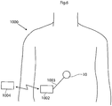
- Fig. 6 illustrates a system for treating urinary retention with an apparatus 10 of the present invention schematically shown placed in the abdomen of a patient.
- the apparatus 10 can be any of those discussed in the context of Figs. 1-5 or as generally described in previous section of the description.
- An implanted energy-transforming device 1002 is adapted to supply energy consuming components of the apparatus with energy via a power supply line 1003.
- An external energy-transmission device 1004 for non-invasively energizing the apparatus 10 transmits energy by at least one wireless energy signal.
- the implanted energy-transforming device 1002 transforms energy from the wireless energy signal into electric energy which is supplied via the power supply line 1003.
- the wireless energy signal may include a wave signal selected from the following: a sound wave signal, an ultrasound wave signal, an electromagnetic wave signal, an infrared light signal, a visible light signal, an ultra violet light signal, a laser light signal, a micro wave signal, a radio wave signal, an x-ray radiation signal and a gamma radiation signal.
- the wireless energy signal may include an electric or magnetic field, or a combined electric and magnetic field.
- the wireless energy-transmission device 1004 may transmit a carrier signal for carrying the wireless energy signal.
- a carrier signal may include digital, analogue or a combination of digital and analogue signals.
- the wireless energy signal includes an analogue or a digital signal, or a combination of an analogue and digital signal.
- the energy-transforming device 1002 is provided for transforming wireless energy of a first form transmitted by the energy-transmission device 1004 into energy of a second form, which typically is different from the energy of the first form.
- the implanted apparatus 10 is operable in response to the energy of the second form.
- the energy-transforming device 1002 may directly power the apparatus with the second form energy, as the energy-transforming device 1002 transforms the first form energy transmitted by the energy-transmission device 1004 into the second form energy.
- the system may further include an implantable accumulator, wherein the second form energy is used at least partly to charge the accumulator.
- the wireless energy transmitted by the energy-transmission device 1004 may be used to directly power the apparatus, as the wireless energy is being transmitted by the energy-transmission device 1004.
- the system comprises an operation device for operating the apparatus, as will be described below, the wireless energy transmitted by the energy-transmission device 1004 may be used to directly power the operation device to create kinetic energy for the operation of the apparatus.
- the wireless energy of the first form may comprise sound waves and the energy-transforming device 1002 may include a piezo-electric element for transforming the sound waves into electric energy.
- the energy of the second form may comprise electric energy in the form of a direct current or pulsating direct current, or a combination of a direct current and pulsating direct current, or an alternating current or a combination of a direct and alternating current.
- the apparatus comprises electric components that are energized with electrical energy.
- Other implantable electric components of the system may be at least one voltage level guard or at least one constant current guard connected with the electric components of the apparatus.
- one of the energy of the first form and the energy of the second form may comprise magnetic energy, kinetic energy, sound energy, chemical energy, radiant energy, electromagnetic energy, photo energy, nuclear energy or thermal energy.
- one of the energy of the first form and the energy of the second form is non-magnetic, non-kinetic, non-chemical, non-sonic, non-nuclear or non-thermal.
- the energy-transmission device may be controlled from outside the patient's body to release electromagnetic wireless energy, and the released electromagnetic wireless energy is used for operating the apparatus.
- the energy-transmission device is controlled from outside the patient's body to release non-magnetic wireless energy, and the released non-magnetic wireless energy is used for operating the apparatus.
- the external energy-transmission device 1004 also includes a wireless remote control having an external signal transmitter for transmitting a wireless control signal for non-invasively controlling the apparatus.
- the control signal is received by an implanted signal receiver which may be incorporated in the implanted energy-transforming device 1002 or be separate there from.
- the wireless control signal may include a frequency, amplitude, or phase modulated signal or a combination thereof.
- the wireless control signal includes an analogue or a digital signal, or a combination of an analogue and digital signal.
- the wireless control signal comprises an electric or magnetic field, or a combined electric and magnetic field.
- the wireless remote control may transmit a carrier signal for carrying the wireless control signal.
- a carrier signal may include digital, analogue or a combination of digital and analogue signals.
- the control signal includes an analogue or a digital signal, or a combination of an analogue and digital signal
- the wireless remote control preferably transmits an electromagnetic carrier wave signal for carrying the digital or analogue control signals.
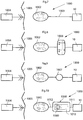
- Fig. 7 illustrates the system of Fig. 6 in the form of a more generalized block diagram showing the apparatus 10, the energy-transforming device 1002 powering the apparatus 10 via power supply line 1003, and the external energy-transmission device 1004,
- Fig. 8 shows an embodiment of the invention identical to that of Fig. 7 , except that a reversing device in the form of an electric switch 1006 operable for example by polarized energy also is implanted in the patient for reversing the apparatus 10.
- the wireless remote control of the external energy-transmission device 1004 transmits a wireless signal that carries polarized energy and the implanted energy-transforming device 1002 transforms the wireless polarized energy into a polarized current for operating the electric switch 1006.
- the electric switch 1006 reverses the function performed by the apparatus 10.
- Fig. 9 shows an embodiment of the invention identical to that of Fig. 7 , except that an operation device 1007 implanted in the patient for operating the apparatus 10 is provided between the implanted energy-transforming device 1002 and the apparatus 10.
- This operation device can be in the form of a motor 1007, such as an electric servomotor.
- the motor 1007 is powered with energy from the implanted energy-transforming device 1002, as the remote control of the external energy-transmission device 1004 transmits a wireless signal to the receiver of the implanted energy-transforming device 1002.
- Fig. 10 shows an embodiment of the invention identical to that of Fig. 7 , except that it also comprises an operation device is in the form of an assembly 1008 including a motor/pump unit 1009 and a fluid reservoir 1010 is implanted in the patient.
- the apparatus 10 is hydraulically operated, i.e. hydraulic fluid is pumped by the motor/pump unit 1009 from the fluid reservoir 1010 through a conduit 1011 to the apparatus 10 to operate the apparatus, and hydraulic fluid is pumped by the motor/pump unit 1009 back from the apparatus 10 to the fluid reservoir 1010 to return the apparatus to a starting position.
- the implanted energy-transforming device 1002 transforms wireless energy into a current, for example a polarized current, for powering the motor/pump unit 1009 via an electric power supply line 1012.
- the operation device comprises a pneumatic operation device.
- the hydraulic fluid can be pressurized air to be used for regulation and the fluid reservoir is replaced by an air chamber.
- the energy-transforming device 1002 may include a rechargeable accumulator like a battery or a capacitor to be charged by the wireless energy and supplies energy for any energy consuming part of the system.
- the wireless remote control described above may be replaced by manual control of any implanted part to make contact with by the patient's hand most likely indirect, for example a press button placed under the skin.
- Fig. 11 shows an embodiment of the invention comprising the external energy-transmission device 1004 with its wireless remote control, the apparatus 10, in this case hydraulically operated, and the implanted energy-transforming device 1002, and further comprising a hydraulic fluid reservoir 1013, a motor/pump unit 1009 and an reversing device in the form of a hydraulic valve shifting device 1014, all implanted in the patient.
- the remote control may be a device separated from the external energy-transmission device or included in the same.
- the motor of the motor/pump unit 1009 is an electric motor.
- the implanted energy-transforming device 1002 powers the motor/pump unit 1009 with energy from the energy carried by the control signal, whereby the motor/pump unit 1009 distributes hydraulic fluid between the hydraulic fluid reservoir 1013 and the apparatus 10.
- the remote control of the external energy-transmission device 1004 controls the hydraulic valve shifting device 1014 to shift the hydraulic fluid flow direction between one direction in which the fluid is pumped by the motor/pump unit 1009 from the hydraulic fluid reservoir 1013 to the apparatus 10 to operate the apparatus, and another opposite direction in which the fluid is pumped by the motor/pump unit 1009 back from the apparatus 10 to the hydraulic fluid reservoir 1013 to return the apparatus to a starting position.
- Fig. 12 shows an embodiment of the invention comprising the external energy-transmission device 1004 with its wireless remote control, the apparatus 10, the implanted energy-transforming device 1002, an implanted internal control unit 1015 controlled by the wireless remote control of the external energy-transmission device 1004, an implanted accumulator 1016 and an implanted capacitor 1017.
- the internal control unit 1015 arranges storage of electric energy received from the implanted energy-transforming device 1002 in the accumulator 1016, which supplies energy to the apparatus 10.
- the internal control unit 1015 In response to a control signal from the wireless remote control of the external energy-transmission device 1004, the internal control unit 1015 either releases electric energy from the accumulator 1016 and transfers the released energy via power lines 1018 and 1019, or directly transfers electric energy from the implanted energy-transforming device 1002 via a power line 1020, the capacitor 1017, which stabilizes the electric current, a power line 1021 and the power line 1019, for the operation of the apparatus 10.
- the internal control unit is preferably programmable from outside the patient's body.
- the internal control unit is programmed to regulate the apparatus 10 according to a pre-programmed time-schedule or to input from any sensor sensing any possible physical parameter of the patient or any functional parameter of the system.
- the capacitor 1017 in the embodiment of Fig. 12 may be omitted.
- the accumulator 1016 in this embodiment may be omitted.
- Fig. 13 shows an example identical to that of Fig. 7 , except that a battery 1022 for supplying energy for the operation of the apparatus 10 and an electric switch 1023 for switching the operation of the apparatus 10 also are implanted in the patient.
- the electric switch 1023 may be controlled by the remote control and may also be operated by the energy supplied by the implanted energy-transforming device 1002 to switch from an off mode, in which the battery 1022 is not in use, to an on mode, in which the battery 1022 supplies energy for the operation of the apparatus 10.
- Fig. 14 shows an example identical to that of Fig. 13 , except that an internal control unit 1015 controllable by the wireless remote control of the external energy-transmission device 1004 also is implanted in the patient.
- the electric switch 1023 is operated by the energy supplied by the implanted energy-transforming device 1002 to switch from an off mode, in which the wireless remote control is prevented from controlling the internal control unit 1015 and the battery is not in use, to a standby mode, in which the remote control is permitted to control the internal control unit 1015 to release electric energy from the battery 1022 for the operation of the apparatus 10.
- Fig. 15 shows an example identical to that of Fig. 14 , except that an accumulator 1016 is substituted for the battery 1022 and the implanted components are interconnected differently.
- the accumulator 1016 stores energy from the implanted energy-transforming device 1002.
- the internal control unit 1015 controls the electric switch 1023 to switch from an off mode, in which the accumulator 1016 is not in use, to an on mode, in which the accumulator 1016 supplies energy for the operation of the apparatus 10.
- the accumulator may be combined with or replaced by a capacitor.
- Fig. 16 shows an example identical to that of Fig. 15 , except that a battery 1022 also is implanted in the patient and the implanted components are interconnected differently.
- the internal control unit 1015 controls the accumulator 1016 to deliver energy for operating the electric switch 1023 to switch from an off mode, in which the battery 1022 is not in use, to an on mode, in which the battery 1022 supplies electric energy for the operation of the apparatus 10.
- the electric switch 1023 may be operated by energy supplied by the accumulator 1016 to switch from an off mode, in which the wireless remote control is prevented from controlling the battery 1022 to supply electric energy and is not in use, to a standby mode, in which the wireless remote control is permitted to control the battery 1022 to supply electric energy for the operation of the apparatus 10.
- switch 1023 and all other switches in this application should be interpreted in its broadest embodiment.
- the switch is controlled from outside the body, or alternatively by an implanted internal control unit.
- Fig. 17 shows an embodiment of the invention identical to the example of Fig. 13 , except that a motor 1007, a mechanical reversing device in the form of a gear box 1024, and an internal control unit 1015 for controlling the gear box 1024 also are implanted in the patient.
- the internal control unit 1015 controls the gear box 1024 to reverse the function performed by the apparatus 10 (mechanically operated). Even simpler is to switch the direction of the motor electronically.
- the gear box interpreted in its broadest embodiment may stand for a servo arrangement saving force for the operation device in favour of longer stroke to act.
- Fig. 18 shows an example identical to that of Fig. 24 except that the implanted components are interconnected differently.
- the internal control unit 1015 is powered by the battery 1022 when the accumulator 1016, suitably a capacitor, activates the electric switch 1023 to switch to an on mode.
- the electric switch 1023 is in its on mode the internal control unit 1015 is permitted to control the battery 1022 to supply, or not supply, energy for the operation of the apparatus 10.
- Fig. 19 schematically shows conceivable combinations of implanted components of the apparatus for achieving various communication options.
- the apparatus 10 the internal control unit 1015, motor or pump unit 1009, and the external energy-transmission device 1004 including the external wireless remote control.
- the wireless remote control transmits a control signal which is received by the internal control unit 1015, which in turn controls the various implanted components of the apparatus.
- a feedback device preferably comprising a sensor or measuring device 1025, may be implanted in the patient for sensing a physical parameter of the patient.
- the physical parameter may be at least one selected from the group consisting of pressure, volume, diameter, stretching, elongation, extension, movement, bending, elasticity, muscle contraction, nerve impulse, body temperature, blood pressure, blood flow, heartbeats and breathing.
- the sensor may sense any of the above physical parameters.
- the sensor may be a pressure or motility sensor.
- the sensor 1025 may be arranged to sense a functional parameter.
- the functional parameter may be correlated to the transfer of energy for charging an implanted energy source and may further include at least one selected from the group of parameters consisting of; electricity, any electrical parameter, pressure, volume, diameter, stretc, elongation, extension, movement, bending, elasticity, temperature and flow.
- the feedback may be sent to the internal control unit or out to an external control unit preferably via the internal control unit.
- Feedback may be sent out from the body via the energy transfer system or a separate communication system with receiver and transmitters.
- the internal control unit 1015 may control the apparatus 10 in response to signals from the sensor 1025.
- a transceiver may be combined with the sensor 1025 for sending information on the sensed physical parameter to the external wireless remote control.
- the wireless remote control may comprise a signal transmitter or transceiver and the internal control unit 1015 may comprise a signal receiver or transceiver.
- the wireless remote control may comprise a signal receiver or transceiver and the internal control unit 1015 may comprise a signal transmitter or transceiver.
- the above transceivers, transmitters and receivers may be used for sending information or data related to the apparatus 10 from inside the patient's body to the outside thereof.
- Fig. 20 shows an alternative embodiment wherein the apparatus 10 is regulated from outside the patient's body.
- the system 1000 comprises a battery 1022 connected to the apparatus 10 via a subcutaneous electric switch 1026.
- the regulation of the apparatus 10 is performed non-invasively by manually pressing the subcutaneous switch, whereby the operation of the apparatus 10 is switched on and off.
- additional components such as an internal control unit or any other part disclosed in the present application can be added to the system.
- Two subcutaneous switches may also be used.
- one implanted switch sends information to the internal control unit to perform a certain predetermined performance and when the patient press the switch again the performance is reversed.
- Fig. 21 shows an alternative embodiment, wherein the system 1000 comprises a hydraulic fluid reservoir 1013 hydraulically connected to the apparatus. Non-invasive regulation is performed by manually pressing the hydraulic reservoir connected to the apparatus.
- the system may include an external data communicator and an implantable internal data communicator communicating with the external data communicator.
- the internal communicator feeds data related to the apparatus or the patient to the external data communicator and/or the external data communicator feeds data to the internal data communicator.
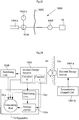
- Fig. 22 schematically illustrates an arrangement of the system that is capable of sending information from inside the patient's body to the outside thereof to give feedback information related to at least one functional parameter of the apparatus or system, or related to a physical parameter of the patient, in order to supply an accurate amount of energy to an implanted internal energy receiver 1002 connected to implanted energy consuming components of the apparatus 10.
- an energy receiver 1002 may include an energy source and/or an energy-transforming device. Briefly described, wireless energy is transmitted from an external energy source 1004a located outside the patient and is received by the internal energy receiver 1002 located inside the patient.
- the internal energy receiver is adapted to directly or indirectly supply received energy to the energy consuming components of the apparatus 10 via a switch 1026.
- An energy balance is determined between the energy received by the internal energy receiver 1002 and the energy used for the apparatus 10, and the transmission of wireless energy is then controlled based on the determined energy balance.
- the energy balance thus provides an accurate indication of the correct amount of energy needed, which is sufficient to operate the apparatus 10 properly, but without causing undue temperature rise.
- the energy receiver comprises an energy-transforming device 1002 located inside the patient, preferably just beneath the patient's skin 1005.
- the implanted energy-transforming device 1002 may be placed in the abdomen, thorax, muscle fascia (e.g. in the abdominal wall), subcutaneously, or at any other suitable location.
- the implanted energy-transforming device 1002 is adapted to receive wireless energy E transmitted from the external energy-source 1004a provided in an external energy-transmission device 1004 located outside the patient's skin 1005 in the vicinity of the implanted energy-transforming device 1002.
- the wireless energy E may generally be transferred by means of any suitable Transcutaneous Energy Transfer (TET) device, such as a device including a primary coil arranged in the external energy source 1004a and an adjacent secondary coil arranged in the implanted energy-transforming device 1002.
- TET Transcutaneous Energy Transfer
- TET Transcutaneous Energy Transfer
- the present invention is generally not limited to any particular energy transfer technique, TET devices or energy sources, and any kind of wireless energy may be used.
- the amount of energy received by the implanted energy receiver may be compared with the energy used by the implanted components of the apparatus.
- the term "energy used” is then understood to include also energy stored by implanted components of the apparatus.
- a control device includes an external control unit 1004b that controls the external energy source 1004a based on the determined energy balance to regulate the amount of transferred energy.
- the energy balance and the required amount of energy is determined by means of a determination device including an implanted internal control unit 1015 connected between the switch 1026 and the apparatus 10.
- the internal control unit 1015 may thus be arranged to receive various measurements obtained by suitable sensors or the like, not shown, measuring certain characteristics of the apparatus 10, somehow reflecting the required amount of energy needed for proper operation of the apparatus 10.
- the current condition of the patient may also be detected by means of suitable measuring devices or sensors, in order to provide parameters reflecting the patient's condition.
- suitable measuring devices or sensors in order to provide parameters reflecting the patient's condition.
- characteristics and/or parameters may be related to the current state of the apparatus 10, such as power consumption, operational mode and temperature, as well as the patient's condition reflected by parameters such as; body temperature, blood pressure, heartbeats and breathing.
- Other kinds of physical parameters of the patient and functional parameters of the device are described elsewhere.
- an energy source in the form of an accumulator 1016 may optionally be connected to the implanted energy-transforming device 1002 via the control unit 1015 for accumulating received energy for later use by the apparatus 10.
- characteristics of such an accumulator also reflecting the required amount of energy, may be measured as well.
- the accumulator may be replaced by a rechargeable battery, and the measured characteristics may be related to the current state of the battery, any electrical parameter such as energy consumption voltage, temperature, etc. In order to provide sufficient voltage and current to the apparatus 10, and also to avoid excessive heating, it is clearly understood that the battery should be charged optimally by receiving a correct amount of energy from the implanted energy-transforming device 1002, i.e. not too little or too much.
- the accumulator may also be a capacitor with corresponding characteristics.
- battery characteristics may be measured on a regular basis to determine the current state of the battery, which then may be stored as state information in a suitable storage means in the internal control unit 1015.
- state information in a suitable storage means in the internal control unit 1015.
- the internal control unit 1015 of the determination device is adapted to determine the energy balance and/or the currently required amount of energy, (either energy per time unit or accumulated energy) based on measurements made by the above-mentioned sensors or measuring devices of the apparatus 10, or the patient, or an implanted energy source if used, or any combination thereof.
- the internal control unit 1015 is further connected to an internal signal transmitter 1027, arranged to transmit a control signal reflecting the determined required amount of energy, to an external signal receiver 1004c connected to the external control unit 1004b.
- the amount of energy transmitted from the external energy source 1004a may then be regulated in response to the received control signal.
- the determination device may include the external control unit 1004b.
- sensor measurements can be transmitted directly to the external control unit 1004b wherein the energy balance and/or the currently required amount of energy can be determined by the external control unit 1004b, thus integrating the above-described function of the internal control unit 1015 in the external control unit 1004b.
- the internal control unit 1015 can be omitted and the sensor measurements are supplied directly to the internal signal transmitter 1027 which sends the measurements over to the external signal receiver 1004c and the external control unit 1004b. The energy balance and the currently required amount of energy can then be determined by the external control unit 1004b based on those sensor measurements.
- the present solution according to the arrangement of Fig. 22 employs the feed back of information indicating the required energy, which is more efficient than previous solutions because it is based on the actual use of energy that is compared to the received energy, e.g. with respect to the amount of energy, the energy difference, or the energy receiving rate as compared to the energy rate used by implanted energy consuming components of the apparatus.
- the apparatus may use the received energy either for consuming or for storing the energy in an implanted energy source or the like.
- the different parameters discussed above would thus be used if relevant and needed and then as a tool for determining the actual energy balance. However, such parameters may also be needed per se for any actions taken internally to specifically operate the apparatus.
- the internal signal transmitter 1027 and the external signal receiver 1004c may be implemented as separate units using suitable signal transfer means, such as radio, IR (Infrared) or ultrasonic signals.
- suitable signal transfer means such as radio, IR (Infrared) or ultrasonic signals.
- the internal signal transmitter 1027 and the external signal receiver 1004c may be integrated in the implanted energy-transforming device 1002 and the external energy source 1004a, respectively, so as to convey control signals in a reverse direction relative to the energy transfer, basically using the same transmission technique.
- the control signals may be modulated with respect to frequency, phase or amplitude.
- the feedback information may be transferred either by a separate communication system including receivers and transmitters or may be integrated in the energy system.
- an integrated information feedback and energy system comprises an implantable internal energy receiver for receiving wireless energy, the energy receiver having an internal first coil and a first electronic circuit connected to the first coil, and an external energy transmitter for transmitting wireless energy, the energy transmitter having an external second coil and a second electronic circuit connected to the second coil.
- the external second coil of the energy transmitter transmits wireless energy which is received by the first coil of the energy receiver.
- This system further comprises a power switch for switching the connection of the internal first coil to the first electronic circuit on and off, such that feedback information related to the charging of the first coil is received by the external energy transmitter in the form of an impedance variation in the load of the external second coil, when the power switch switches the connection of the internal first coil to the first electronic circuit on and off.
- the switch 1026 is either separate and controlled by the internal control unit 1015, or integrated in the internal control unit 1015. It should be understood that the switch 1026 should be interpreted in its broadest embodiment. This means a transistor, MCU, MCPU, ASIC FPGA or a DA converter or any other electronic component or circuit that may switch the power on and off.
- the energy supply arrangement illustrated in Fig. 22 may operate basically in the following manner.
- the energy balance is first determined by the internal control unit 1015 of the determination device.
- a control signal reflecting the required amount of energy is also created by the internal control unit 1015, and the control signal is transmitted from the internal signal transmitter 1027 to the external signal receiver 1004c.
- the energy balance can be determined by the external control unit 1004b instead depending on the implementation, as mentioned above.
- the control signal may carry measurement results from various sensors.
- the amount of energy emitted from the external energy source 1004a can then be regulated by the external control unit 1004b, based on the determined energy balance, e.g. in response to the received control signal. This process may be repeated intermittently at certain intervals during ongoing energy transfer, or may be executed on a more or less continuous basis during the energy transfer.
- the amount of transferred energy can generally be regulated by adjusting various transmission parameters in the external energy source 1004a, such as voltage, current, amplitude, wave frequency and pulse characteristics.
- This system may also be used to obtain information about the coupling factors between the coils in a TET system even to calibrate the system both to find an optimal place for the external coil in relation to the internal coil and to optimize energy transfer. Simply comparing in this case the amount of energy transferred with the amount of energy received. For example if the external coil is moved the coupling factor may vary and correctly displayed movements could cause the external coil to find the optimal place for energy transfer.
- the external coil is adapted to calibrate the amount of transferred energy to achieve the feedback information in the determination device, before the coupling factor is maximized.
- the energy system of the present invention comprises an implantable internal energy receiver for receiving wireless energy, the energy receiver having an internal first coil and a first electronic circuit connected to the first coil, and an external energy transmitter for transmitting wireless energy, the energy transmitter having an external second coil and a second electronic circuit connected to the second coil.
- the external second coil of the energy transmitter transmits wireless energy which is received by the first coil of the energy receiver.
- This system further comprises a feedback device for communicating out the amount of energy received in the first coil as a feedback information
- the second electronic circuit includes a determination device for receiving the feedback information and for comparing the amount of transferred energy by the second coil with the feedback information related to the amount of energy received in the first coil to obtain the coupling factor between the first and second coils.
- the energy transmitter may regulate the transmitted energy in response to the obtained coupling factor.
- FIG. 23 Although wireless transfer of energy for operating the apparatus has been described above to enable non-invasive operation, it will be appreciated that the apparatus can be operated with wire bound energy as well.
- an external switch 1026 is interconnected between the external energy source 1004a and an operation device, such as an electric motor 1007 operating the apparatus 10.
- An external control unit 1004b controls the operation of the external switch 1026 to effect proper operation of the apparatus 10.
- Fig. 24 illustrates different embodiments for how received energy can be supplied to and used by the apparatus 10.
- an internal energy receiver 1002 receives wireless energy E from an external energy source 1004a which is controlled by a transmission control unit 1004b.
- the internal energy receiver 1002 may comprise a constant voltage circuit, indicated as a dashed box “constant V" in the figure, for supplying energy at constant voltage to the apparatus 10.
- the internal energy receiver 1002 may further comprise a constant current circuit, indicated as a dashed box "constant C" in the figure, for supplying energy at constant current to the apparatus 10.
- the apparatus 10 comprises an energy consuming part 10a, which may be a motor, pump, restriction device, or any other medical appliance that requires energy for its electrical operation.
- the apparatus 10 may further comprise an energy storage device 10b for storing energy supplied from the internal energy receiver 1002.
- the supplied energy may be directly consumed by the energy consuming part 10a, or stored by the energy storage device 10b, or the supplied energy may be partly consumed and partly stored.
- the apparatus 10 may further comprise an energy stabilizing unit 10c for stabilizing the energy supplied from the internal energy receiver 1002.
- the energy may be supplied in a fluctuating manner such that it may be necessary to stabilize the energy before consumed or stored.
- the energy supplied from the internal energy receiver 1002 may further be accumulated and/or stabilized by a separate energy stabilizing unit 1028 located outside the apparatus 10, before being consumed and/or stored by the apparatus 10.
- the energy stabilizing unit 1028 may be integrated in the internal energy receiver 1002.
- the energy stabilizing unit 1028 may comprise a constant voltage circuit and/or a constant current circuit.
- Fig. 22 and Fig. 24 illustrate some possible but non-limiting implementation options regarding how the various shown functional components and elements can be arranged and connected to each other.
- Fig. 22 and Fig. 24 illustrate some possible but non-limiting implementation options regarding how the various shown functional components and elements can be arranged and connected to each other.
- the skilled person will readily appreciate that many variations and modifications can be made within the scope of the present invention.
- Fig. 25 schematically shows an energy balance measuring circuit of one of the proposed designs of the system for controlling transmission of wireless energy, or energy balance control system.
- the circuit has an output signal centered on 2.5V and proportionally related to the energy imbalance. The derivative of this signal shows if the value goes up and down and how fast such a change takes place. If the amount of received energy is lower than the energy used by implanted components of the apparatus, more energy is transferred and thus charged into the energy source.
- the output signal from the circuit is typically feed to an A/D converter and converted into a digital format. The digital information can then be sent to the external energy-transmission device allowing it to adjust the level of the transmitted energy.
- Another possibility is to have a completely analog system that uses comparators comparing the energy balance level with certain maximum and minimum thresholds sending information to external energy-transmission device if the balance drifts out of the max/min window.
- the schematic Fig. 25 shows a circuit implementation for a system that transfers energy to the implanted energy components of the apparatus of the present invention from outside of the patient's body using inductive energy transfer.
- An inductive energy transfer system typically uses an external transmitting coil and an internal receiving coil.
- the receiving coil, L1 is included in the schematic Fig. 3 ; the transmitting parts of the system are excluded.
- Fig. 25 the symbols Y1, Y2, Y3 and so on symbolize test points within the circuit.
- the components in the diagram and their respective values are values that work in this particular implementation which of course is only one of an infinite number of possible design solutions.
- Energy to power the circuit is received by the energy receiving coil L1. Energy to implanted components is transmitted in this particular case at a frequency of 25 kHz.
- the energy balance output signal is present at test point Y1.
- the electric switch 1006 of Fig. 8 could be incorporated in any of the embodiments of Figs. 11-17
- the hydraulic valve shifting device 1014 of Fig. 11 could be incorporated in the embodiment of Fig. 10
- the gear box 1024 could be incorporated in the embodiment of Fig. 9 .
- the switch simply could mean any electronic circuit or component.
- a method for controlling transmission of wireless energy supplied to implanted energy consuming components of an apparatus as described above.
- the wireless energy E is transmitted from an external energy source located outside the patient and is received by an internal energy receiver located inside the patient, the internal energy receiver being connected to the implanted energy consuming components of the apparatus for directly or indirectly supplying received energy thereto.
- An energy balance is determined between the energy received by the internal energy receiver and the energy used for the apparatus.
- the transmission of wireless energy E from the external energy source is then controlled based on the determined energy balance.
- the wireless energy may be transmitted inductively from a primary coil in the external energy source to a secondary coil in the internal energy receiver.
- a change in the energy balance may be detected to control the transmission of wireless energy based on the detected energy balance change.
- a difference may also be detected between energy received by the internal energy receiver and energy used for the medical device, to control the transmission of wireless energy based on the detected energy difference.
- the amount of transmitted wireless energy may be decreased if the detected energy balance change implies that the energy balance is increasing, or vice versa.
- the decrease/increase of energy transmission may further correspond to a detected change rate.
- the amount of transmitted wireless energy may further be decreased if the detected energy difference implies that the received energy is greater than the used energy, or vice versa.
- the decrease/increase of energy transmission may then correspond to the magnitude of the detected energy difference.
- the energy used for the medical device may be consumed to operate the medical device, and/or stored in at least one energy storage device of the medical device.
- the energy may be transmitted for consumption and storage according to a transmission rate per time unit which is determined based on said parameters.
- the total amount of transmitted energy may also be determined based on said parameters.
- the integral may be determined for a monitored voltage and/or current related to the energy balance.
- the derivative When the derivative is determined over time of a measured electrical parameter related to the amount of consumed and/or stored energy, the derivative may be determined for a monitored voltage and/or current related to the energy balance.
- the transmission of wireless energy from the external energy source may be controlled by applying to the external energy source electrical pulses from a first electric circuit to transmit the wireless energy, the electrical pulses having leading and trailing edges, varying the lengths of first time intervals between successive leading and trailing edges of the electrical pulses and/or the lengths of second time intervals between successive trailing and leading edges of the electrical pulses, and transmitting wireless energy, the transmitted energy generated from the electrical pulses having a varied power, the varying of the power depending on the lengths of the first and/or second time intervals.
- the frequency of the electrical pulses may be substantially constant when varying the first and/or second time intervals.
- the electrical pulses may remain unchanged, except for varying the first and/or second time intervals.
- the amplitude of the electrical pulses may be substantially constant when varying the first and/or second time intervals. Further, the electrical pulses may be varied by only varying the lengths of first time intervals between successive leading and trailing edges of the electrical pulses.
- a train of two or more electrical pulses may be supplied in a row, wherein when applying the train of pulses, the train having a first electrical pulse at the start of the pulse train and having a second electrical pulse at the end of the pulse train, two or more pulse trains may be supplied in a row, wherein the lengths of the second time intervals between successive trailing edge of the second electrical pulse in a first pulse train and leading edge of the first electrical pulse of a second pulse train are varied.
- the electrical pulses When applying the electrical pulses, the electrical pulses may have a substantially constant current and a substantially constant voltage.
- the electrical pulses may also have a substantially constant current and a substantially constant voltage. Further, the electrical pulses may also have a substantially constant frequency.
- the electrical pulses within a pulse train may likewise have a substantially constant frequency.
- the circuit formed by the first electric circuit and the external energy source may have a first characteristic time period or first time constant, and when effectively varying the transmitted energy, such frequency time period may be in the range of the first characteristic time period or time constant or shorter.
- a system comprising an apparatus as described above is thus also provided for controlling transmission of wireless energy supplied to implanted energy consuming components of the apparatus.
- the system comprises a control device for controlling the transmission of wireless energy from an energy-transmission device, and an implantable internal energy receiver for receiving the transmitted wireless energy, the internal energy receiver being connected to implantable energy consuming components of the apparatus for directly or indirectly supplying received energy thereto.
- the system further comprises a determination device adapted to determine an energy balance between the energy received by the internal energy receiver and the energy used for the implantable energy consuming components of the apparatus, wherein the control device controls the transmission of wireless energy from the external energy-transmission device, based on the energy balance determined by the determination device.
- system may comprise any of the following:
- Figs. 26-29 show in more detail block diagrams of four different ways of hydraulically or pneumatically powering an implanted apparatus according to the invention.
- Fig. 26 shows a system as described above with.
- the system comprises an implanted apparatus 10 and further a separate regulation reservoir 1013, a one way pump 1009 and an alternate valve 1014.
- Fig. 27 shows the apparatus 10 and a fluid reservoir 1013.
- Fig. 28 shows the apparatus 10, a two way pump 1009 and the regulation reservoir 1013.
- Fig. 29 shows a block diagram of a reversed servo system with a first closed system controlling a second closed system.
- the servo system comprises a regulation reservoir 1013 and a servo reservoir 1050.
- the servo reservoir 1050 mechanically controls an implanted apparatus 10 via a mechanical interconnection 1054.
- the apparatus has an expandable/contactable cavity. This cavity is preferably expanded or contracted by supplying hydraulic fluid from the larger adjustable reservoir 1052 in fluid connection with the apparatus 10. Alternatively, the cavity contains compressible gas, which can be compressed and expanded under the control of the servo reservoir 1050.
- the servo reservoir 1050 can also be part of the apparatus itself.
- the regulation reservoir is placed subcutaneous under the patient's skin and is operated by pushing the outer surface thereof by means of a finger.
- This system is illustrated in Figs 30a-c .
- a flexible subcutaneous regulation reservoir 1013 is shown connected to a bulge shaped servo reservoir 1050 by means of a conduit 1011.
- This bellow shaped servo reservoir 1050 is comprised in a flexible apparatus 10.
- the servo reservoir 1050 contains a minimum of fluid and most fluid is found in the regulation reservoir 1013. Due to the mechanical interconnection between the servo reservoir 1050 and the apparatus 10, the outer shape of the apparatus 10 is contracted, i.e., it occupies less than its maximum volume. This maximum volume is shown with dashed lines in the figure.
- Fig. 30b shows a state wherein a user, such as the patient in with the apparatus is implanted, presses the regulation reservoir 1013 so that fluid contained therein is brought to flow through the conduit 1011 and into the servo reservoir 1050, which, thanks to its bellow shape, expands longitudinally. This expansion in turn expands the apparatus 10 so that it occupies its maximum volume, thereby stretching the stomach wall (not shown), which it contacts.
- the regulation reservoir 1013 is preferably provided with means 1013a for keeping its shape after compression. This means, which is schematically shown in the figure, will thus keep the apparatus 10 in a stretched position also when the user releases the regulation reservoir. In this way, the regulation reservoir essentially operates as an on/off switch for the system.
- FIG. 31 comprises with a first closed system controlling a second closed system.
- the first system comprises a regulation reservoir 1013 and a servo reservoir 1050.
- the servo reservoir 1050 mechanically controls a larger adjustable reservoir 1052 via a mechanical interconnection 1054.
- An implanted apparatus 10 having an expandable/contactable cavity is in turn controlled by the larger adjustable reservoir 1052 by supply of hydraulic fluid from the larger adjustable reservoir 1052 in fluid connection with the apparatus 10.
- the regulation reservoir is placed subcutaneous under the patient's skin and is operated by pushing the outer surface thereof by means of a finger.
- the regulation reservoir 1013 is in fluid connection with a bellow shaped servo reservoir 1050 by means of a conduit 1011.
- the servo reservoir 1050 contains a minimum of fluid and most fluid is found in the regulation reservoir 1013.
- the servo reservoir 1050 is mechanically connected to a larger adjustable reservoir 1052, in this example also having a bellow shape but with a larger diameter than the servo reservoir 1050.
- the larger adjustable reservoir 1052 is in fluid connection with the apparatus 10. This means that when a user pushes the regulation reservoir 1013, thereby displacing fluid from the regulation reservoir 1013 to the servo reservoir 1050, the expansion of the servo reservoir 1050 will displace a larger volume of fluid from the larger adjustable reservoir 1052 to the apparatus 10. In other words, in this reversed servo, a small volume in the regulation reservoir is compressed with a higher force and this creates a movement of a larger total area with less force per area unit.
- the regulation reservoir 1013 is preferably provided with means 1013a for keeping its shape after compression. This means, which is schematically shown in the figure, will thus keep the apparatus 10 in a stretched position also when the user releases the regulation reservoir. In this way, the regulation reservoir essentially operates as an on/off switch for the system.
Landscapes
- Health & Medical Sciences (AREA)
- Life Sciences & Earth Sciences (AREA)
- Surgery (AREA)
- Public Health (AREA)
- Veterinary Medicine (AREA)
- Engineering & Computer Science (AREA)
- Biomedical Technology (AREA)
- Heart & Thoracic Surgery (AREA)
- General Health & Medical Sciences (AREA)
- Animal Behavior & Ethology (AREA)
- Molecular Biology (AREA)
- Medical Informatics (AREA)
- Vascular Medicine (AREA)
- Biophysics (AREA)
- Physics & Mathematics (AREA)
- Pathology (AREA)
- Urology & Nephrology (AREA)
- Cardiology (AREA)
- Reproductive Health (AREA)
- Transplantation (AREA)
- Oral & Maxillofacial Surgery (AREA)
- Nuclear Medicine, Radiotherapy & Molecular Imaging (AREA)
- Hematology (AREA)
- Gynecology & Obstetrics (AREA)
- Physiology (AREA)
- Prostheses (AREA)
- External Artificial Organs (AREA)
- Surgical Instruments (AREA)
- Electrotherapy Devices (AREA)
Claims (29)
- Vorrichtung, die zur Behandlung der Harnretention eines Säugetierpatienten durch die Ausscheidung von Urin aus der Harnblase eingerichtet ist, umfassend:ein implantierbares angetriebenes Element (100) mit einem Harnblasenoberflächenkontaktteil, wobei das angetriebene Element eingerichtet ist, um eine Kraft von außen auf einen ausgewählten Teil der Harnblase auszuüben, um Urin aus der Harnblase auszuscheiden;eine Stützstruktur, die eingerichtet ist, um sich gegen mindestens eines von einem Knochen oder anderem menschlichen Gewebe, wie etwa dem Beckenknochen, dem Schambein oder dem Kreuzbein, einem anderen menschlichen Gewebe, wie etwa dem Bauchfell, der Bauch- oder Beckenwand oder der Urinblase selbst abzustützen; undeine Steuervorrichtung (200) zum Steuern des Betriebs des angetriebenen Elements,wobei die Vorrichtung dadurch gekennzeichnet ist, dass die Kraft des angetriebenen Elements, die auf die Harnblase ausgeübt wird, mindestens teilweise gegen die Stützstruktur ausgeübt wird, wenn Urin aus der Harnblase ausgeschieden wird.
- Vorrichtung nach einem der Ansprüche 1, wobei die Steuervorrichtung eine Energiequelle zum Betreiben des angetriebenen Elements und anderer energieverbrauchender Teile der Vorrichtung aufweist.
- Vorrichtung nach einem der Ansprüche 1 bis 2, wobei die Steuervorrichtung eingerichtet ist, mindestens teilweise subkutan oder in den Bauch- oder in den Beckenbereich implantiert zu werden.
- Vorrichtung nach einem der Ansprüche 1 bis 3, wobei die Steuervorrichtung eine Steueranordnung umfasst, die eingerichtet ist, sowohl subkutan als auch in der Bauchhöhle implantiert zu werden, wobei die Steueranordnung mindestens zwei Teile umfasst, die eingerichtet sind, nach dem Implantieren verbunden zu werden.
- Vorrichtung nach einem der Ansprüche 1 bis 4, wobei das angetriebene Element mindestens einen betreibbaren Druckhalter (140) umfasst, der mit einem Kontaktteil in einer Anordnung verbunden ist, wobei das Betreiben des Druckhalters eine Kompression oder Freisetzung der Harnblase bereitstellt.
- Vorrichtung nach einem der Ansprüche 1 bis 5, wobei das angetriebene Element hydraulisch betätigt wird, um das Zusammendrücken oder Freigeben der Harnblase bereitzustellen.
- Vorrichtung nach einem der Ansprüche 1 bis 5, wobei das angetriebene Element mechanisch betätigt wird, um das Zusammendrücken oder Freigeben der Harnblase bereitzustellen.
- Vorrichtung nach Anspruch 7, umfassend mindestens einen beweglichen Arm (142), der sich von einer Betätigungsvorrichtung (144) zu einem Kontaktteil (120) des angetriebenen Elements erstreckt, der eingerichtet ist, einen Oberflächenteil der Harnblase zu kontaktieren, wobei die Betätigungsvorrichtung (144) eingerichtet ist, den beweglichen Arm in Richtung der Harnblase zu verschieben, um Urin aus der Harnblase auszuscheiden, wobei die Betätigungsvorrichtung (144) einen Motor umfasst, der eingerichtet ist, den beweglichen Arm zu verschieben.
- Vorrichtung nach Anspruch 5, wobei der Druckhalter einen Vorratsbehälter für Hydraulikfluid umfasst, wobei der Kontaktteil (120) eingerichtet ist, um einen Oberflächenteil der Harnblase zu kontaktieren, vorzugsweise den oberen Teil der Harnblase, und wobei der Kontaktteil einen expandierbaren Hohlraum umfasst, der hydraulisch mit dem Vorratsbehälter verbunden ist.
- Vorrichtung nach Anspruch 8, wobei die Betätigungsvorrichtung (144) an menschlichem Gewebe befestigt ist, wobei die Betätigungsvorrichtung zur Befestigung am Schambein eingerichtet ist.
- Vorrichtung nach Anspruch 9, wobei der Druckhalter eine Pumpe zum Transportieren des Hydraulikfluids aus dem Vorratsbehälter umfasst, um den ausdehnbaren Hohlraum auszudehnen, um dadurch die Harnblase zusammenzudrücken.
- Vorrichtung nach Anspruch 11, wobei der Druckhalter eingerichtet ist, um das Hydraulikfluid durch den Harndruck in der Harnblase von dem ausdehnbaren Hohlraum zu dem Behälter transportieren zu lassen, wenn die Pumpe nicht aktiv ist.
- Vorrichtung nach Anspruch 5, wobei der betätigbare Druckhalter eine Betätigungsvorrichtung umfasst, die an einer Stützvorrichtung befestigt ist, die eingerichtet ist, dass sie an der Harnblasenwand befestigt werden kann.
- Vorrichtung nach Anspruch 13, wobei die Stützvorrichtung im Allgemeinen ringförmig ist oder eine intermittierende Ringform aufweist, wobei sich die Stützvorrichtung entlang des Umfangs der Harnblase erstreckt.
- Vorrichtung nach einem der Ansprüche 1 bis 12, umfassend eine Betätigungsvorrichtung zum Betreiben des angetriebenen Elements, wobei die Betätigungsvorrichtung mindestens eines von a) mindestens einem Motor, vorzugsweise eine Servoeinrichtung aufweisend, die dazu konstruiert ist, die für den Motor zum Betreiben der Vorrichtung erforderliche Kraft zu verringern, anstatt den Motor länger arbeiten zu lassen, was die Zeit für eine bestimmte Aktion erhöht, und b) mindestens eine Pumpe zum Betreiben der Vorrichtung umfasst, wobei die Pumpe dazu eingerichtet ist, eine hydraulische Betätigungsvorrichtung zum Betätigen der Vorrichtung zu betreiben.
- Vorrichtung nach einem der Ansprüche 1 bis 15, wobei die Steuervorrichtung ferner eine Vorrichtung zum elektrischen Stimulieren der Muskeln der Harnblase zum Zusammenziehen der Muskeln umfasst.
- Vorrichtung nach Anspruch 16, wobei die elektrisch stimulierende Vorrichtung eine Vielzahl von Elektroden umfasst, die an den Muskeln der Harnblase angebracht sind.
- Vorrichtung nach einem der Ansprüche 1 bis 17, umfassend ein implantierbares Paar von Restriktionseinrichtungen, wobei die Steuervorrichtung die Restriktionseinrichtungen steuert, die eingerichtet sind, um die Harnleiter zu schließen, wenn Urin aus der Harnblase ausgeschieden wird.
- Vorrichtung nach einem der Ansprüche 1 bis 18, umfassend einen künstlichen Blasenschließmuskel, wobei eine durch die Steuervorrichtung gesteuerte Restriktionseinrichtung als Blasenschließmuskel wirkt.
- Vorrichtung nach einem der Ansprüche 1 bis 19, umfassend einen Sensor zum Messen eines beliebigen Parameters, der mit dem Harndruck oder dem Volumen der Harnblase in Verbindung steht, wobei der Sensor in der Lage ist, ein Signal an die Steuervorrichtung zu senden, die dadurch eingerichtet ist, eine Alarminformation aus dem Körper als Anforderung zur Aktivierung des angetriebenen Elements zu senden.
- Vorrichtung nach einem der Ansprüche 1 bis 20, die ferner mindestens eines der Folgenden umfasst: a) mindestens einen in den Patienten implantierbaren Schalter zum manuellen und nicht-invasiven Steuern der Vorrichtung, b) eine hydraulische Vorrichtung, die einen implantierbaren Hydraulik-Vorratsbehälter aufweist, der hydraulisch mit der Vorrichtung verbunden ist, wobei die Vorrichtung eingerichtet ist, durch manuelles Drücken des Hydraulik-Vorratsbehälters nicht-invasiv geregelt zu werden, und c) eine drahtlose Fernbedienung zum nicht-invasiven Steuern der Vorrichtung.
- System, umfassend eine Vorrichtung nach einem der Ansprüche 1 bis 21, umfassend eine implantierbare interne Energiequelle zur Energieversorgung von implantierbaren energieverbrauchenden Komponenten der Vorrichtung.
- Vorrichtung nach einem der Ansprüche 1 bis 21 oder einem System nach Anspruch 22, ferner umfassend eine drahtlose Energieübertragungsvorrichtung zur nicht-invasiven Speisung von implantierbaren energieverbrauchenden Komponenten der Vorrichtung mit drahtloser Energie.
- Vorrichtung nach einem der Ansprüche 1 bis 21 oder einem System nach Anspruch 22 oder 23, ferner umfassend eine Energieumwandlungsvorrichtung zum Umwandeln der von der Energieumwandlungsvorrichtung übertragenen drahtlosen Energie von einer ersten Form in eine zweite Form von Energie, wobei die Energieumwandlungsvorrichtung eingerichtet ist, um mindestens eines der Folgenden durchzuführen; a) direktes Versorgen von implantierbaren energieverbrauchenden Komponenten der Vorrichtung mit der zweiten Energieform oder b) wenn das System ferner eine implantierbare interne Energiequelle zur Energieversorgung von implantierbaren energieverbrauchenden Komponenten der Vorrichtung, die durch die drahtlose Energie aufladbar ist, umfasst, die interne Energiequelle mit der zweiten Energieform zu versorgen, da die energieumwandelnde Vorrichtung die erste Form der von der Energieübertragungsvorrichtung übertragenen Energie in die zweite Energieform umwandelt.
- Geräteeinrichtung nach einem der Ansprüche 1 bis 21 oder einem System nach Anspruch 22, ferner umfassend eine Rückmeldeeinrichtung zum Senden von Rückmeldeinformationen aus dem Inneren des Körpers des Patienten nach der Außenseite davon, wobei sich die Rückmeldeinformationen auf mindestens einen der physikalischen Parameter des Patienten und einen mit der Vorrichtung zusammenhängenden funktionellen Parameter beziehen, wobei mindestens ein funktioneller Parameter mit der Übertragung von drahtloser Energie korreliert ist.
- Vorrichtung nach einem der Ansprüche 1 bis 21 oder ein System nach Anspruch 22, ferner umfassend einen Sensor und/oder eine Messvorrichtung und eine implantierbare interne Steuereinheit zum Steuern der Vorrichtung in Reaktion auf Informationen, die mit mindestens einem von a) einem durch den Sensor erfassten oder durch die Messvorrichtung gemessenen physikalischen Parameter des Patienten und b) einem mit der Vorrichtung zusammenhängenden, durch den Sensor erfassten oder durch die Messvorrichtung gemessenen funktionellen Parameter in Zusammenhang stehen.
- Vorrichtung nach einem der Ansprüche 1 bis 21 oder ein System nach Anspruch 22, ferner umfassend eine Steuervorrichtung zum Steuern der Übertragung von drahtloser Energie von der Energieübertragungsvorrichtung und einen implantierbaren internen Energieempfänger zum Empfangen der übertragenen drahtlosen Energie, wobei der interne Energieempfänger mit implantierbaren energieverbrauchenden Komponenten der Vorrichtung verbunden ist, um ihr direkt oder indirekt empfangene Energie zuzuführen, wobei das System ferner eine Bestimmungsvorrichtung umfasst, die eingerichtet ist, um eine Energiebilanz zwischen der von dem internen Energieempfänger empfangenen Energie und der Energie zu bestimmen, die für die implantierbaren energieverbrauchenden Komponenten der Vorrichtung verwendet wird, wobei die Steuervorrichtung die Übertragung von drahtloser Energie von der externen Energieübertragungsvorrichtung basierend auf der von der Bestimmungsvorrichtung bestimmten Energiebilanz steuert, wobei die Bestimmungsvorrichtung eingerichtet ist, um mindestens eines von; a) einer Änderung in der Energiebilanz, und die Steuervorrichtung steuert die Übertragung von drahtloser Energie basierend auf der erfassten Energiebilanzveränderung und b) eine Differenz zwischen der vom internen Energieempfänger empfangenen Energie und der Energie zu erfassen, die für die implantierbaren energieverbrauchenden Komponenten der Vorrichtung verwendet wird, und die Steuervorrichtung steuert die Übertragung von drahtloser Energie basierend auf der erfassten Energiedifferenz.
- Vorrichtung nach einem der Ansprüche 1 bis 21 oder ein System nach Anspruch 22, ferner umfassend implantierbare elektrische Komponenten, die mindestens einen Spannungspegelbegrenzer und/oder mindestens einen Konstantstrombegrenzer umfassen.
- Geräteeinrichtung nach einem der Ansprüche 1 bis 21 oder ein System nach Anspruch 22, ferner umfassend einen externen Datenkommunikator und einen implantierbaren internen Datenkommunikator, der mit dem externen Datenkommunikator kommuniziert, wobei der interne Kommunikator dem externen Datenkommunikator die mit der Vorrichtung oder dem Patienten zusammenhängenden Daten zuführt, und/oder der externe Datenkommunikator dem internen Datenkommunikator Daten zuführt.
Priority Applications (1)
| Application Number | Priority Date | Filing Date | Title |
|---|---|---|---|
| EP18211392.8A EP3485845B1 (de) | 2007-10-11 | 2008-10-10 | Implantierbare vorrichtung zur externen harnflusskontrolle |
Applications Claiming Priority (3)
| Application Number | Priority Date | Filing Date | Title |
|---|---|---|---|
| US96071507P | 2007-10-11 | 2007-10-11 | |
| US96071607P | 2007-10-11 | 2007-10-11 | |
| PCT/SE2008/000560 WO2009048373A1 (en) | 2007-10-11 | 2008-10-10 | Implantable device for external urinary control |
Related Child Applications (1)
| Application Number | Title | Priority Date | Filing Date |
|---|---|---|---|
| EP18211392.8A Division EP3485845B1 (de) | 2007-10-11 | 2008-10-10 | Implantierbare vorrichtung zur externen harnflusskontrolle |
Publications (3)
| Publication Number | Publication Date |
|---|---|
| EP2211767A1 EP2211767A1 (de) | 2010-08-04 |
| EP2211767A4 EP2211767A4 (de) | 2016-01-20 |
| EP2211767B1 true EP2211767B1 (de) | 2018-12-12 |
Family
ID=54208494
Family Applications (2)
| Application Number | Title | Priority Date | Filing Date |
|---|---|---|---|
| EP08838487.0A Active EP2211767B1 (de) | 2007-10-11 | 2008-10-10 | Implantierbare vorrichtung zur externen harnwegskontrolle |
| EP18211392.8A Active EP3485845B1 (de) | 2007-10-11 | 2008-10-10 | Implantierbare vorrichtung zur externen harnflusskontrolle |
Family Applications After (1)
| Application Number | Title | Priority Date | Filing Date |
|---|---|---|---|
| EP18211392.8A Active EP3485845B1 (de) | 2007-10-11 | 2008-10-10 | Implantierbare vorrichtung zur externen harnflusskontrolle |
Country Status (8)
| Country | Link |
|---|---|
| US (1) | US9351664B2 (de) |
| EP (2) | EP2211767B1 (de) |
| JP (2) | JP2011500135A (de) |
| CN (1) | CN101888816B (de) |
| AU (1) | AU2008311424B2 (de) |
| CA (1) | CA2739826C (de) |
| ES (1) | ES2714789T3 (de) |
| WO (1) | WO2009048373A1 (de) |
Families Citing this family (28)
| Publication number | Priority date | Publication date | Assignee | Title |
|---|---|---|---|---|
| CA2776467A1 (en) * | 2008-10-10 | 2010-04-15 | Peter Forsell | Fastening means for implantable medical control assembly |
| EP2451386B1 (de) * | 2009-07-10 | 2015-08-19 | Kirk Promotion LTD. | Implantierbare medizinische vorrichtung zur schmierung einer künstlichen kontaktfläche |
| CN102596104B (zh) * | 2009-07-10 | 2016-01-20 | 米卢克斯控股股份有限公司 | 可植入式润滑装置和包括该装置的系统 |
| KR20220000916A (ko) * | 2009-07-10 | 2022-01-04 | 메디칼트리 페이턴트 엘티디. | 이식가능한 윤활 장치 |
| RU2590861C9 (ru) * | 2009-07-10 | 2016-10-10 | Милакс Холдинг С.А. | Имплантируемое смазочное устройство |
| SI3170476T1 (sl) * | 2009-07-10 | 2022-01-31 | Medicaltree Patent Ltd. | Implantabilna mazalna naprava |
| RU2712082C2 (ru) * | 2009-07-10 | 2020-01-24 | МедикалТри Патент Лтд. | Имплантируемое смазочное устройство |
| US8594806B2 (en) | 2010-04-30 | 2013-11-26 | Cyberonics, Inc. | Recharging and communication lead for an implantable device |
| CN102370534B (zh) * | 2011-10-24 | 2013-07-10 | 广东工业大学 | 一种超声汽化蒸汽驱动的排尿助力系统 |
| US9343923B2 (en) | 2012-08-23 | 2016-05-17 | Cyberonics, Inc. | Implantable medical device with backscatter signal based communication |
| US9935498B2 (en) | 2012-09-25 | 2018-04-03 | Cyberonics, Inc. | Communication efficiency with an implantable medical device using a circulator and a backscatter signal |
| BR112015023553B1 (pt) * | 2013-03-15 | 2021-12-07 | Implantica Patent Ltd. | Dispositivo de restrição |
| ES2677574T3 (es) * | 2013-04-08 | 2018-08-03 | Boston Scientific Scimed, Inc. | Sistemas médicos |
| CA2924817C (en) | 2013-09-16 | 2023-09-19 | The Board Of Trustees Of The Leland Stanford Junior University | Multi-element coupler for generation of electromagnetic energy |
| US20160336813A1 (en) | 2015-05-15 | 2016-11-17 | NeuSpera Medical Inc. | Midfield coupler |
| EP3294173B1 (de) | 2014-05-18 | 2020-07-15 | Neuspera Medical Inc. | Mittelfeldkoppler |
| JP2019524389A (ja) | 2016-06-10 | 2019-09-05 | ジャック ウィリアムズ | 生体電気事象を無線で記録及び刺激するためのシステム |
| US11045650B2 (en) | 2016-12-06 | 2021-06-29 | Medtronic, Inc. | High frequency neurostimulation for pelvic symptom control |
| CN106580517B (zh) * | 2017-01-23 | 2018-05-25 | 夏生俊 | 一种人工膀胱装置 |
| WO2018187734A1 (en) | 2017-04-07 | 2018-10-11 | Medtronic, Inc. | Complex variation of electrical stimulation therapy parameters |
| US11191962B2 (en) | 2018-03-12 | 2021-12-07 | Purdue Research Foundation | Stimulus coil and pulse generator for wireless glaucoma therapy |
| CN109009594B (zh) * | 2018-06-25 | 2020-09-29 | 温州医科大学附属第一医院 | 一种膀胱活动力辅助装置及使用方法 |
| WO2020033775A1 (en) * | 2018-08-08 | 2020-02-13 | Incube Labs, Llc | Apparatus, systems and methods for sensing bladder fullness |
| US11826516B2 (en) * | 2020-06-24 | 2023-11-28 | Charles Winston Weisse | Ureteral bypass devices and procedures |
| IL300651A (en) | 2020-08-31 | 2023-04-01 | Implantica Patent Ltd | Methods and devices for communication and secure operation of an implant |
| WO2023156516A1 (en) | 2022-02-18 | 2023-08-24 | Implantica Patent Ltd | Methods and devices for secure communication with and operation of an implant |
| WO2023031047A1 (en) | 2021-08-30 | 2023-03-09 | Implantica Patent Ltd | A device for secure communication with and operation of an implant |
| WO2024170748A1 (en) | 2023-02-16 | 2024-08-22 | Implantica Patent Ltd | Methods and devices for secure communication with and operation of an implant |
Family Cites Families (27)
| Publication number | Priority date | Publication date | Assignee | Title |
|---|---|---|---|---|
| FR2116838A5 (fr) * | 1970-12-09 | 1972-07-21 | Sowinski Kazimierz Maria | Prothese destinee a remplacer la vessie d'un patient |
| FR2347030A1 (fr) * | 1975-08-04 | 1977-11-04 | Guiset Jacques | Vessie prothetique |
| US5123428A (en) * | 1988-10-11 | 1992-06-23 | Schwarz Gerald R | Laparoscopically implanting bladder control apparatus |
| US4969474A (en) | 1988-10-11 | 1990-11-13 | Schwarz Gerald R | Incontinence bladder control method and apparatus |
| US5876425A (en) * | 1989-09-22 | 1999-03-02 | Advanced Bionics Corporation | Power control loop for implantable tissue stimulator |
| EP0996482B1 (de) | 1997-07-16 | 2007-02-14 | Metacure NV | Einrichtung zur steuerung eines glatten muskels |
| US6074341A (en) | 1998-06-09 | 2000-06-13 | Timm Medical Technologies, Inc. | Vessel occlusive apparatus and method |
| US6482145B1 (en) | 2000-02-14 | 2002-11-19 | Obtech Medical Ag | Hydraulic anal incontinence treatment |
| US6461292B1 (en) * | 1999-08-12 | 2002-10-08 | Obtech Medical Ag | Anal incontinence treatment with wireless energy supply |
| US6393323B1 (en) | 2000-01-31 | 2002-05-21 | Mcgill University | Electronic stimulator implant for modulating and synchronizing bladder and sphincter function |
| ES2309622T3 (es) * | 2000-02-10 | 2008-12-16 | Potencia Medical Ag | Tratamiento controlado de incontinencia urinaria. |
| MXPA02007648A (es) | 2000-02-10 | 2004-08-23 | Potencia Medical Ag | Tratamiento de incontinencia anal con suministro de energia inalambrica controlada. |
| ATE416743T1 (de) | 2000-02-11 | 2008-12-15 | Potentica Ag | Vorrichtung mit energieumwandlungsmitteln zur impotenzbehandlung |
| US6709385B2 (en) * | 2000-02-11 | 2004-03-23 | Obtech Medical Ag | Urinary incontinence treatment apparatus |
| US6432040B1 (en) * | 2000-09-14 | 2002-08-13 | Nizam N. Meah | Implantable esophageal sphincter apparatus for gastroesophageal reflux disease and method |
| US6527701B1 (en) | 2000-09-29 | 2003-03-04 | Precision Medical Devices, Inc. | Body fluid flow control device |
| JP3769469B2 (ja) | 2001-03-28 | 2006-04-26 | 株式会社東芝 | 操作訓練用装置 |
| US20040242956A1 (en) * | 2002-07-29 | 2004-12-02 | Scorvo Sean K. | System for controlling fluid in a body |
| US6772011B2 (en) * | 2002-08-20 | 2004-08-03 | Thoratec Corporation | Transmission of information from an implanted medical device |
| US20040064110A1 (en) | 2002-10-01 | 2004-04-01 | Peter Forsell | Injection port |
| US7273448B2 (en) * | 2003-04-24 | 2007-09-25 | Ams Research Corporation | Male urethral prosthesis |
| US20050266042A1 (en) * | 2004-05-27 | 2005-12-01 | Medtronic Vascular, Inc. | Methods and apparatus for treatment of aneurysmal tissue |
| US20060041309A1 (en) * | 2004-08-20 | 2006-02-23 | Massen Richard J | Linear electromechanical device-based artificial muscles, bio-valves and related applications |
| EP1784143A2 (de) * | 2004-08-25 | 2007-05-16 | Pavad Medical, Inc. | Künstlicher sphinkter |
| US7559951B2 (en) | 2004-09-30 | 2009-07-14 | Depuy Products, Inc. | Adjustable, remote-controllable orthopaedic prosthesis and associated method |
| JP4565184B2 (ja) * | 2004-11-10 | 2010-10-20 | 国立大学法人佐賀大学 | 排尿支援装置 |
| JP4351709B2 (ja) * | 2007-04-03 | 2009-10-28 | メタキュアー エヌブイ | 平滑筋制御装置 |
-
2008
- 2008-10-10 EP EP08838487.0A patent/EP2211767B1/de active Active
- 2008-10-10 EP EP18211392.8A patent/EP3485845B1/de active Active
- 2008-10-10 CN CN200880119735.9A patent/CN101888816B/zh active Active
- 2008-10-10 WO PCT/SE2008/000560 patent/WO2009048373A1/en active Application Filing
- 2008-10-10 JP JP2010528830A patent/JP2011500135A/ja active Pending
- 2008-10-10 CA CA2739826A patent/CA2739826C/en active Active
- 2008-10-10 ES ES08838487T patent/ES2714789T3/es active Active
- 2008-10-10 AU AU2008311424A patent/AU2008311424B2/en active Active
- 2008-10-11 US US12/682,517 patent/US9351664B2/en active Active
-
2014
- 2014-03-19 JP JP2014057067A patent/JP2014131767A/ja active Pending
Non-Patent Citations (1)
| Title |
|---|
| None * |
Also Published As
| Publication number | Publication date |
|---|---|
| CA2739826A1 (en) | 2009-04-16 |
| EP3485845A1 (de) | 2019-05-22 |
| CA2739826C (en) | 2021-08-31 |
| WO2009048373A1 (en) | 2009-04-16 |
| EP3485845B1 (de) | 2023-06-07 |
| ES2714789T3 (es) | 2019-05-30 |
| EP3485845C0 (de) | 2023-06-07 |
| EP2211767A1 (de) | 2010-08-04 |
| CN101888816B (zh) | 2014-12-17 |
| AU2008311424A1 (en) | 2009-04-16 |
| JP2014131767A (ja) | 2014-07-17 |
| CN101888816A (zh) | 2010-11-17 |
| US9351664B2 (en) | 2016-05-31 |
| AU2008311424B2 (en) | 2015-02-12 |
| US20100228079A1 (en) | 2010-09-09 |
| EP2211767A4 (de) | 2016-01-20 |
| JP2011500135A (ja) | 2011-01-06 |
Similar Documents
| Publication | Publication Date | Title |
|---|---|---|
| US12011603B2 (en) | Implantable device for external urinary control | |
| US12053363B2 (en) | Implantable device for internal urinary control | |
| EP2211767B1 (de) | Implantierbare vorrichtung zur externen harnwegskontrolle | |
| US11191628B2 (en) | Implantable device for internal urinary control | |
| CA3225412A1 (en) | Implantable device for external urinary control |
Legal Events
| Date | Code | Title | Description |
|---|---|---|---|
| PUAI | Public reference made under article 153(3) epc to a published international application that has entered the european phase |
Free format text: ORIGINAL CODE: 0009012 |
|
| 17P | Request for examination filed |
Effective date: 20100511 |
|
| AK | Designated contracting states |
Kind code of ref document: A1 Designated state(s): AT BE BG CH CY CZ DE DK EE ES FI FR GB GR HR HU IE IS IT LI LT LU LV MC MT NL NO PL PT RO SE SI SK TR |
|
| AX | Request for extension of the european patent |
Extension state: AL BA MK RS |
|
| DAX | Request for extension of the european patent (deleted) | ||
| RAP1 | Party data changed (applicant data changed or rights of an application transferred) |
Owner name: KIRK PROMOTION LTD. |
|
| RA4 | Supplementary search report drawn up and despatched (corrected) |
Effective date: 20151221 |
|
| RIC1 | Information provided on ipc code assigned before grant |
Ipc: A61B 17/12 20060101ALI20151215BHEP Ipc: A61B 19/00 00000000ALN20151215BHEP Ipc: A61B 5/02 20060101ALI20151215BHEP Ipc: A61B 17/00 20060101ALN20151215BHEP Ipc: A61B 5/07 20060101ALI20151215BHEP Ipc: A61F 2/00 20060101AFI20151215BHEP Ipc: A61F 2/04 20060101ALN20151215BHEP Ipc: A61B 5/00 20060101ALI20151215BHEP Ipc: A61B 17/135 20060101ALI20151215BHEP |
|
| STAA | Information on the status of an ep patent application or granted ep patent |
Free format text: STATUS: EXAMINATION IS IN PROGRESS |
|
| 17Q | First examination report despatched |
Effective date: 20170123 |
|
| RIC1 | Information provided on ipc code assigned before grant |
Ipc: A61B 17/135 20060101ALI20180221BHEP Ipc: A61B 5/07 20060101ALI20180221BHEP Ipc: A61F 2/04 20130101ALN20180221BHEP Ipc: A61B 17/12 20060101ALI20180221BHEP Ipc: A61F 2/00 20060101AFI20180221BHEP Ipc: A61B 5/00 20060101ALI20180221BHEP Ipc: A61B 5/02 20060101ALI20180221BHEP Ipc: A61B 17/00 20060101ALN20180221BHEP |
|
| REG | Reference to a national code |
Ref country code: DE Ref legal event code: R079 Ref document number: 602008058334 Country of ref document: DE Free format text: PREVIOUS MAIN CLASS: A61F0002020000 Ipc: A61F0002000000 |
|
| GRAP | Despatch of communication of intention to grant a patent |
Free format text: ORIGINAL CODE: EPIDOSNIGR1 |
|
| STAA | Information on the status of an ep patent application or granted ep patent |
Free format text: STATUS: GRANT OF PATENT IS INTENDED |
|
| RIC1 | Information provided on ipc code assigned before grant |
Ipc: A61B 17/00 20060101ALN20180426BHEP Ipc: A61B 5/00 20060101ALI20180426BHEP Ipc: A61B 5/07 20060101ALI20180426BHEP Ipc: A61B 5/02 20060101ALI20180426BHEP Ipc: A61B 17/135 20060101ALI20180426BHEP Ipc: A61B 17/12 20060101ALI20180426BHEP Ipc: A61F 2/04 20060101ALN20180426BHEP Ipc: A61F 2/00 20060101AFI20180426BHEP |
|
| INTG | Intention to grant announced |
Effective date: 20180528 |
|
| GRAS | Grant fee paid |
Free format text: ORIGINAL CODE: EPIDOSNIGR3 |
|
| RIN1 | Information on inventor provided before grant (corrected) |
Inventor name: FORSELL, PETER |
|
| GRAA | (expected) grant |
Free format text: ORIGINAL CODE: 0009210 |
|
| STAA | Information on the status of an ep patent application or granted ep patent |
Free format text: STATUS: THE PATENT HAS BEEN GRANTED |
|
| AK | Designated contracting states |
Kind code of ref document: B1 Designated state(s): AT BE BG CH CY CZ DE DK EE ES FI FR GB GR HR HU IE IS IT LI LT LU LV MC MT NL NO PL PT RO SE SI SK TR |
|
| REG | Reference to a national code |
Ref country code: GB Ref legal event code: FG4D |
|
| REG | Reference to a national code |
Ref country code: CH Ref legal event code: EP |
|
| REG | Reference to a national code |
Ref country code: AT Ref legal event code: REF Ref document number: 1075002 Country of ref document: AT Kind code of ref document: T Effective date: 20181215 |
|
| REG | Reference to a national code |
Ref country code: DE Ref legal event code: R096 Ref document number: 602008058334 Country of ref document: DE |
|
| REG | Reference to a national code |
Ref country code: IE Ref legal event code: FG4D |
|
| REG | Reference to a national code |
Ref country code: SE Ref legal event code: TRGR |
|
| REG | Reference to a national code |
Ref country code: NL Ref legal event code: FP |
|
| REG | Reference to a national code |
Ref country code: LT Ref legal event code: MG4D |
|
| PG25 | Lapsed in a contracting state [announced via postgrant information from national office to epo] |
Ref country code: HR Free format text: LAPSE BECAUSE OF FAILURE TO SUBMIT A TRANSLATION OF THE DESCRIPTION OR TO PAY THE FEE WITHIN THE PRESCRIBED TIME-LIMIT Effective date: 20181212 Ref country code: NO Free format text: LAPSE BECAUSE OF FAILURE TO SUBMIT A TRANSLATION OF THE DESCRIPTION OR TO PAY THE FEE WITHIN THE PRESCRIBED TIME-LIMIT Effective date: 20190312 Ref country code: LV Free format text: LAPSE BECAUSE OF FAILURE TO SUBMIT A TRANSLATION OF THE DESCRIPTION OR TO PAY THE FEE WITHIN THE PRESCRIBED TIME-LIMIT Effective date: 20181212 Ref country code: FI Free format text: LAPSE BECAUSE OF FAILURE TO SUBMIT A TRANSLATION OF THE DESCRIPTION OR TO PAY THE FEE WITHIN THE PRESCRIBED TIME-LIMIT Effective date: 20181212 Ref country code: LT Free format text: LAPSE BECAUSE OF FAILURE TO SUBMIT A TRANSLATION OF THE DESCRIPTION OR TO PAY THE FEE WITHIN THE PRESCRIBED TIME-LIMIT Effective date: 20181212 Ref country code: BG Free format text: LAPSE BECAUSE OF FAILURE TO SUBMIT A TRANSLATION OF THE DESCRIPTION OR TO PAY THE FEE WITHIN THE PRESCRIBED TIME-LIMIT Effective date: 20190312 |
|
| REG | Reference to a national code |
Ref country code: ES Ref legal event code: FG2A Ref document number: 2714789 Country of ref document: ES Kind code of ref document: T3 Effective date: 20190530 |
|
| PG25 | Lapsed in a contracting state [announced via postgrant information from national office to epo] |
Ref country code: GR Free format text: LAPSE BECAUSE OF FAILURE TO SUBMIT A TRANSLATION OF THE DESCRIPTION OR TO PAY THE FEE WITHIN THE PRESCRIBED TIME-LIMIT Effective date: 20190313 |
|
| RAP2 | Party data changed (patent owner data changed or rights of a patent transferred) |
Owner name: IMPLANTICA PATENT LTD. |
|
| PG25 | Lapsed in a contracting state [announced via postgrant information from national office to epo] |
Ref country code: PL Free format text: LAPSE BECAUSE OF FAILURE TO SUBMIT A TRANSLATION OF THE DESCRIPTION OR TO PAY THE FEE WITHIN THE PRESCRIBED TIME-LIMIT Effective date: 20181212 Ref country code: CZ Free format text: LAPSE BECAUSE OF FAILURE TO SUBMIT A TRANSLATION OF THE DESCRIPTION OR TO PAY THE FEE WITHIN THE PRESCRIBED TIME-LIMIT Effective date: 20181212 Ref country code: PT Free format text: LAPSE BECAUSE OF FAILURE TO SUBMIT A TRANSLATION OF THE DESCRIPTION OR TO PAY THE FEE WITHIN THE PRESCRIBED TIME-LIMIT Effective date: 20190412 |
|
| PG25 | Lapsed in a contracting state [announced via postgrant information from national office to epo] |
Ref country code: RO Free format text: LAPSE BECAUSE OF FAILURE TO SUBMIT A TRANSLATION OF THE DESCRIPTION OR TO PAY THE FEE WITHIN THE PRESCRIBED TIME-LIMIT Effective date: 20181212 Ref country code: EE Free format text: LAPSE BECAUSE OF FAILURE TO SUBMIT A TRANSLATION OF THE DESCRIPTION OR TO PAY THE FEE WITHIN THE PRESCRIBED TIME-LIMIT Effective date: 20181212 Ref country code: IS Free format text: LAPSE BECAUSE OF FAILURE TO SUBMIT A TRANSLATION OF THE DESCRIPTION OR TO PAY THE FEE WITHIN THE PRESCRIBED TIME-LIMIT Effective date: 20190412 Ref country code: SK Free format text: LAPSE BECAUSE OF FAILURE TO SUBMIT A TRANSLATION OF THE DESCRIPTION OR TO PAY THE FEE WITHIN THE PRESCRIBED TIME-LIMIT Effective date: 20181212 |
|
| REG | Reference to a national code |
Ref country code: DE Ref legal event code: R097 Ref document number: 602008058334 Country of ref document: DE |
|
| PLBE | No opposition filed within time limit |
Free format text: ORIGINAL CODE: 0009261 |
|
| STAA | Information on the status of an ep patent application or granted ep patent |
Free format text: STATUS: NO OPPOSITION FILED WITHIN TIME LIMIT |
|
| PG25 | Lapsed in a contracting state [announced via postgrant information from national office to epo] |
Ref country code: SI Free format text: LAPSE BECAUSE OF FAILURE TO SUBMIT A TRANSLATION OF THE DESCRIPTION OR TO PAY THE FEE WITHIN THE PRESCRIBED TIME-LIMIT Effective date: 20181212 Ref country code: DK Free format text: LAPSE BECAUSE OF FAILURE TO SUBMIT A TRANSLATION OF THE DESCRIPTION OR TO PAY THE FEE WITHIN THE PRESCRIBED TIME-LIMIT Effective date: 20181212 |
|
| 26N | No opposition filed |
Effective date: 20190913 |
|
| PG25 | Lapsed in a contracting state [announced via postgrant information from national office to epo] |
Ref country code: TR Free format text: LAPSE BECAUSE OF FAILURE TO SUBMIT A TRANSLATION OF THE DESCRIPTION OR TO PAY THE FEE WITHIN THE PRESCRIBED TIME-LIMIT Effective date: 20181212 |
|
| REG | Reference to a national code |
Ref country code: AT Ref legal event code: UEP Ref document number: 1075002 Country of ref document: AT Kind code of ref document: T Effective date: 20181212 |
|
| PG25 | Lapsed in a contracting state [announced via postgrant information from national office to epo] |
Ref country code: MC Free format text: LAPSE BECAUSE OF FAILURE TO SUBMIT A TRANSLATION OF THE DESCRIPTION OR TO PAY THE FEE WITHIN THE PRESCRIBED TIME-LIMIT Effective date: 20181212 |
|
| PG25 | Lapsed in a contracting state [announced via postgrant information from national office to epo] |
Ref country code: LU Free format text: LAPSE BECAUSE OF NON-PAYMENT OF DUE FEES Effective date: 20191010 |
|
| PG25 | Lapsed in a contracting state [announced via postgrant information from national office to epo] |
Ref country code: IE Free format text: LAPSE BECAUSE OF NON-PAYMENT OF DUE FEES Effective date: 20191010 |
|
| PG25 | Lapsed in a contracting state [announced via postgrant information from national office to epo] |
Ref country code: CY Free format text: LAPSE BECAUSE OF FAILURE TO SUBMIT A TRANSLATION OF THE DESCRIPTION OR TO PAY THE FEE WITHIN THE PRESCRIBED TIME-LIMIT Effective date: 20181212 |
|
| PG25 | Lapsed in a contracting state [announced via postgrant information from national office to epo] |
Ref country code: MT Free format text: LAPSE BECAUSE OF FAILURE TO SUBMIT A TRANSLATION OF THE DESCRIPTION OR TO PAY THE FEE WITHIN THE PRESCRIBED TIME-LIMIT Effective date: 20181212 Ref country code: HU Free format text: LAPSE BECAUSE OF FAILURE TO SUBMIT A TRANSLATION OF THE DESCRIPTION OR TO PAY THE FEE WITHIN THE PRESCRIBED TIME-LIMIT; INVALID AB INITIO Effective date: 20081010 |
|
| REG | Reference to a national code |
Ref country code: DE Ref legal event code: R081 Ref document number: 602008058334 Country of ref document: DE Owner name: LMPLANTICA PATENT LTD., MT Free format text: FORMER OWNER: KIRK PROMOTION LTD., STOCKHOLM, SE |
|
| REG | Reference to a national code |
Ref country code: GB Ref legal event code: 732E Free format text: REGISTERED BETWEEN 20211230 AND 20220105 |
|
| REG | Reference to a national code |
Ref country code: BE Ref legal event code: PD Owner name: IMPLANTICA PATENT LTD.; MT Free format text: DETAILS ASSIGNMENT: CHANGE OF OWNER(S), ASSIGNMENT; FORMER OWNER NAME: KIRK PROMOTION LTD. Effective date: 20211227 |
|
| REG | Reference to a national code |
Ref country code: NL Ref legal event code: PD Owner name: IMPLANTICA PATENT LTD.; MT Free format text: DETAILS ASSIGNMENT: CHANGE OF OWNER(S), ASSIGNMENT; FORMER OWNER NAME: KIRK PROMOTION LTD. Effective date: 20220211 |
|
| REG | Reference to a national code |
Ref country code: AT Ref legal event code: PC Ref document number: 1075002 Country of ref document: AT Kind code of ref document: T Owner name: IMPLANTICA PATENT LTD., MT Effective date: 20220516 |
|
| PGFP | Annual fee paid to national office [announced via postgrant information from national office to epo] |
Ref country code: NL Payment date: 20230925 Year of fee payment: 16 Ref country code: IT Payment date: 20230919 Year of fee payment: 16 Ref country code: GB Payment date: 20230918 Year of fee payment: 16 |
|
| PGFP | Annual fee paid to national office [announced via postgrant information from national office to epo] |
Ref country code: SE Payment date: 20230918 Year of fee payment: 16 Ref country code: FR Payment date: 20230915 Year of fee payment: 16 Ref country code: BE Payment date: 20230927 Year of fee payment: 16 |
|
| PGFP | Annual fee paid to national office [announced via postgrant information from national office to epo] |
Ref country code: ES Payment date: 20231102 Year of fee payment: 16 |
|
| PGFP | Annual fee paid to national office [announced via postgrant information from national office to epo] |
Ref country code: DE Payment date: 20230919 Year of fee payment: 16 Ref country code: CH Payment date: 20231102 Year of fee payment: 16 Ref country code: AT Payment date: 20230919 Year of fee payment: 16 |