EP2211399A1 - Power supply system - Google Patents
Power supply system Download PDFInfo
- Publication number
- EP2211399A1 EP2211399A1 EP08834737A EP08834737A EP2211399A1 EP 2211399 A1 EP2211399 A1 EP 2211399A1 EP 08834737 A EP08834737 A EP 08834737A EP 08834737 A EP08834737 A EP 08834737A EP 2211399 A1 EP2211399 A1 EP 2211399A1
- Authority
- EP
- European Patent Office
- Prior art keywords
- assembled battery
- voltage
- power supply
- supply system
- battery
- Prior art date
- Legal status (The legal status is an assumption and is not a legal conclusion. Google has not performed a legal analysis and makes no representation as to the accuracy of the status listed.)
- Withdrawn
Links
Images



Classifications
-
- H—ELECTRICITY
- H01—ELECTRIC ELEMENTS
- H01M—PROCESSES OR MEANS, e.g. BATTERIES, FOR THE DIRECT CONVERSION OF CHEMICAL ENERGY INTO ELECTRICAL ENERGY
- H01M10/00—Secondary cells; Manufacture thereof
- H01M10/42—Methods or arrangements for servicing or maintenance of secondary cells or secondary half-cells
- H01M10/44—Methods for charging or discharging
- H01M10/441—Methods for charging or discharging for several batteries or cells simultaneously or sequentially
-
- H—ELECTRICITY
- H01—ELECTRIC ELEMENTS
- H01M—PROCESSES OR MEANS, e.g. BATTERIES, FOR THE DIRECT CONVERSION OF CHEMICAL ENERGY INTO ELECTRICAL ENERGY
- H01M10/00—Secondary cells; Manufacture thereof
- H01M10/05—Accumulators with non-aqueous electrolyte
- H01M10/052—Li-accumulators
-
- H—ELECTRICITY
- H01—ELECTRIC ELEMENTS
- H01M—PROCESSES OR MEANS, e.g. BATTERIES, FOR THE DIRECT CONVERSION OF CHEMICAL ENERGY INTO ELECTRICAL ENERGY
- H01M10/00—Secondary cells; Manufacture thereof
- H01M10/24—Alkaline accumulators
-
- H—ELECTRICITY
- H01—ELECTRIC ELEMENTS
- H01M—PROCESSES OR MEANS, e.g. BATTERIES, FOR THE DIRECT CONVERSION OF CHEMICAL ENERGY INTO ELECTRICAL ENERGY
- H01M10/00—Secondary cells; Manufacture thereof
- H01M10/24—Alkaline accumulators
- H01M10/30—Nickel accumulators
-
- H—ELECTRICITY
- H01—ELECTRIC ELEMENTS
- H01M—PROCESSES OR MEANS, e.g. BATTERIES, FOR THE DIRECT CONVERSION OF CHEMICAL ENERGY INTO ELECTRICAL ENERGY
- H01M10/00—Secondary cells; Manufacture thereof
- H01M10/34—Gastight accumulators
- H01M10/345—Gastight metal hydride accumulators
-
- H—ELECTRICITY
- H01—ELECTRIC ELEMENTS
- H01M—PROCESSES OR MEANS, e.g. BATTERIES, FOR THE DIRECT CONVERSION OF CHEMICAL ENERGY INTO ELECTRICAL ENERGY
- H01M10/00—Secondary cells; Manufacture thereof
- H01M10/42—Methods or arrangements for servicing or maintenance of secondary cells or secondary half-cells
- H01M10/4207—Methods or arrangements for servicing or maintenance of secondary cells or secondary half-cells for several batteries or cells simultaneously or sequentially
-
- H—ELECTRICITY
- H01—ELECTRIC ELEMENTS
- H01M—PROCESSES OR MEANS, e.g. BATTERIES, FOR THE DIRECT CONVERSION OF CHEMICAL ENERGY INTO ELECTRICAL ENERGY
- H01M10/00—Secondary cells; Manufacture thereof
- H01M10/42—Methods or arrangements for servicing or maintenance of secondary cells or secondary half-cells
- H01M10/48—Accumulators combined with arrangements for measuring, testing or indicating the condition of cells, e.g. the level or density of the electrolyte
- H01M10/482—Accumulators combined with arrangements for measuring, testing or indicating the condition of cells, e.g. the level or density of the electrolyte for several batteries or cells simultaneously or sequentially
-
- H—ELECTRICITY
- H01—ELECTRIC ELEMENTS
- H01M—PROCESSES OR MEANS, e.g. BATTERIES, FOR THE DIRECT CONVERSION OF CHEMICAL ENERGY INTO ELECTRICAL ENERGY
- H01M4/00—Electrodes
- H01M4/02—Electrodes composed of, or comprising, active material
- H01M4/36—Selection of substances as active materials, active masses, active liquids
- H01M4/48—Selection of substances as active materials, active masses, active liquids of inorganic oxides or hydroxides
- H01M4/52—Selection of substances as active materials, active masses, active liquids of inorganic oxides or hydroxides of nickel, cobalt or iron
- H01M4/525—Selection of substances as active materials, active masses, active liquids of inorganic oxides or hydroxides of nickel, cobalt or iron of mixed oxides or hydroxides containing iron, cobalt or nickel for inserting or intercalating light metals, e.g. LiNiO2, LiCoO2 or LiCoOxFy
-
- H—ELECTRICITY
- H02—GENERATION; CONVERSION OR DISTRIBUTION OF ELECTRIC POWER
- H02J—ELECTRIC POWER NETWORKS; CIRCUIT ARRANGEMENTS OR SYSTEMS FOR SUPPLYING OR DISTRIBUTING ELECTRIC POWER; SYSTEMS FOR STORING ELECTRIC ENERGY
- H02J7/00—Circuit arrangements for charging or discharging batteries or for supplying loads from batteries
- H02J7/34—Parallel operation in networks using both storage and other DC sources, e.g. providing buffering
-
- H—ELECTRICITY
- H02—GENERATION; CONVERSION OR DISTRIBUTION OF ELECTRIC POWER
- H02J—ELECTRIC POWER NETWORKS; CIRCUIT ARRANGEMENTS OR SYSTEMS FOR SUPPLYING OR DISTRIBUTING ELECTRIC POWER; SYSTEMS FOR STORING ELECTRIC ENERGY
- H02J7/00—Circuit arrangements for charging or discharging batteries or for supplying loads from batteries
- H02J7/50—Circuit arrangements for charging or discharging batteries or for supplying loads from batteries acting upon multiple batteries simultaneously or sequentially
-
- H—ELECTRICITY
- H02—GENERATION; CONVERSION OR DISTRIBUTION OF ELECTRIC POWER
- H02J—ELECTRIC POWER NETWORKS; CIRCUIT ARRANGEMENTS OR SYSTEMS FOR SUPPLYING OR DISTRIBUTING ELECTRIC POWER; SYSTEMS FOR STORING ELECTRIC ENERGY
- H02J7/00—Circuit arrangements for charging or discharging batteries or for supplying loads from batteries
- H02J7/50—Circuit arrangements for charging or discharging batteries or for supplying loads from batteries acting upon multiple batteries simultaneously or sequentially
- H02J7/575—Parallel/serial switching of connection of batteries to charge or load circuit
-
- Y—GENERAL TAGGING OF NEW TECHNOLOGICAL DEVELOPMENTS; GENERAL TAGGING OF CROSS-SECTIONAL TECHNOLOGIES SPANNING OVER SEVERAL SECTIONS OF THE IPC; TECHNICAL SUBJECTS COVERED BY FORMER USPC CROSS-REFERENCE ART COLLECTIONS [XRACs] AND DIGESTS
- Y02—TECHNOLOGIES OR APPLICATIONS FOR MITIGATION OR ADAPTATION AGAINST CLIMATE CHANGE
- Y02E—REDUCTION OF GREENHOUSE GAS [GHG] EMISSIONS, RELATED TO ENERGY GENERATION, TRANSMISSION OR DISTRIBUTION
- Y02E60/00—Enabling technologies; Technologies with a potential or indirect contribution to GHG emissions mitigation
- Y02E60/10—Energy storage using batteries
-
- Y—GENERAL TAGGING OF NEW TECHNOLOGICAL DEVELOPMENTS; GENERAL TAGGING OF CROSS-SECTIONAL TECHNOLOGIES SPANNING OVER SEVERAL SECTIONS OF THE IPC; TECHNICAL SUBJECTS COVERED BY FORMER USPC CROSS-REFERENCE ART COLLECTIONS [XRACs] AND DIGESTS
- Y02—TECHNOLOGIES OR APPLICATIONS FOR MITIGATION OR ADAPTATION AGAINST CLIMATE CHANGE
- Y02T—CLIMATE CHANGE MITIGATION TECHNOLOGIES RELATED TO TRANSPORTATION
- Y02T10/00—Road transport of goods or passengers
- Y02T10/60—Other road transportation technologies with climate change mitigation effect
- Y02T10/70—Energy storage systems for electromobility, e.g. batteries
Definitions
- the present invention relates to a power supply system having a cell assembly in which a plurality of cells are combined, and more specifically relates to technology of causing the cell assembly to function as a power source without overcharging the cell as a secondary battery.
- An alkaline storage battery such as a nickel hydride storage battery and a nickel cadmium storage battery
- a nonaqueous electrolyte secondary battery such as a lithium ion secondary battery and a lithium polymer secondary battery have higher energy density per unit weight than a lead storage battery, and are attracting attention as a power source to be mounted on mobile objects such as vehicles and portable devices.
- cells made up of a plurality of nonaqueous electrolyte secondary batteries are connected in series to configure a cell assembly with high energy density per unit weight, and mounted on a vehicle as a cell starter power supply (so-called power source that is not a drive source of the vehicle) in substitute for a lead storage battery, it is considered to be promising for use in races and the like.
- the lead storage battery has a reaction mechanism that is suitable for charge/discharge with a relatively large current, it cannot be said that the foregoing secondary batteries are suitable for charge/discharge with a large current from the perspective of their reaction mechanism. Specifically, the foregoing secondary batteries have the following drawbacks at the end stage of charging.
- an alkaline storage battery such as a nickel hydride storage battery or a nickel cadmium storage battery
- oxygen gas is generated from the positive electrode at the end stage of charging, but when the atmospheric temperature becomes high, the charging voltage of the battery will drop pursuant to the drop in the voltage that generates oxygen gas from the positive electrode; that is, the oxygen overvoltage.
- nonaqueous electrolyte secondary battery such as a lithium ion secondary battery or a lithium polymer secondary battery
- electrolytic solution containing a nonaqueous electrolyte tends to decompose at the end stage of charging, this tendency becomes prominent when the atmospheric temperature increases, and there is a possibility that the cells configuring the assembled battery will deform due to the rise in the inner pressure of the battery.
- Patent Document 1 In order to overcome the foregoing problems, as shown in Patent Document 1, it would be effective to pass additional current from a separate circuit (lateral flow circuit) at the time that the charge of the assembled battery to be used as the power source is complete.
- the lateral flow circuit can be materialized as the following two modes.
- the first mode is the mode of configuring the lateral flow circuit in the form of supplying current to the other in-vehicle electrically powered equipment (lamp, car stereo, air conditioner and the like).
- the second mode is the mode of configuring the lateral flow circuit in the form of simply supplying current to a resistor that consumes current.
- Patent Document 1 Japanese Patent Application Laid-open No. H07-059266
- An object of this invention is to provide a safe and secure power supply system that uses a secondary battery with high energy density per unit weight, and which is capable of easily inhibiting the deformation of such secondary battery even upon receiving all currents from a generator as a charging current.
- the power supply system comprises: a cell assembly in which a first assembled battery, made up of a plurality of first cells connected in series, and a second assembled battery, made up of a plurality of second cells connected in series, are connected in parallel; and a generator that charges the cell assembly.
- the cell assembly is configured such that an average charging voltage V1 as a terminal voltage when the first assembled battery reaches a charging capacity that is half of a full charge capacity is set to be a voltage that is smaller than an average charging voltage V2 as a terminal voltage when the second assembled battery reaches a charging capacity that is half of a full charge capacity.
- a resistor is connected in series to the first assembled battery.
- an average charging voltage V1 of the first assembled battery is set to be a voltage that is smaller than an average charging voltage V2 of the second assembled battery.
- a resistor is connected in series to the first assembled battery.
- the charging voltage of the first assembled battery can be made to appear to be a large charging voltage.
- the difference (change in voltage sought based on the product of the resistance value and current of the resistor) of the charging voltage according to the charging current is added to the true voltage of the first assembled battery, the relation of the charging voltage will appear to be the opposite (first assembled battery > second assembled battery).
- the charging current from the generator will be preferentially supplied to the second assembled battery.
- an alkaline storage battery such as a nickel hydride storage battery or a nickel cadmium storage battery or a nonaqueous electrolyte secondary battery such as a lithium ion secondary battery or a lithium polymer secondary battery with high energy density per unit weight as the secondary battery
- a safe and secure power supply system capable of receiving all currents from the generator as a charging current while reducing the possibility of inducing problems such as the deformation of the secondary battery.
- the deformation of the secondary battery can be inhibited even if all currents from the generator are received as the charging current by adopting the power supply system of the present invention.
- the present invention is particularly effective when using a cell starter power supply that needs to constantly receive a charging current from the generator.
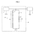
- Fig. 1 is a block diagram explaining the configuration of a power supply system according to an embodiment of the present invention.
- Fig. 1 is a block diagram explaining the configuration of a power supply system according to an embodiment of the present invention.
- the power supply system 40 comprises a generator 1 and a cell assembly 20.
- the generator 1 is used for charging the cell assembly 20 and, for instance, is a generator that is mounted on a vehicle and having a constant voltage specification for generating power based on the rotary motion of the engine.
- the cell assembly 20 includes a first assembled battery 2a in which a plurality (four in the configuration of Fig. 1 ) of cells ⁇ (first cells) are connected in series and a second assembled battery 2b in which a plurality (twelve in the configuration of Fig. 1 ) of cells ⁇ (second cells) are connected in series, and the first assembled battery 2a and the second assembled battery 2b are connected in parallel.
- a charging current is randomly supplied from the generator 1 to the first assembled battery 2a and the second assembled battery 2b.
- the configuration is such that a resistor 3 is connected in series to a terminal (positive electrode) on the generator 1 side of the first assembled battery 2a, and the charging current from the generator 1 is supplied to the generator 1 via the resistor 3.
- an in-car device 5 Connected to the power supply system 40 is an in-car device 5 as an example of a load.
- the in-car device 5 is, for example, a load device such as a cell starter for starting the vehicle engine, lights, car navigation system or the like.
- the positive electrode of the first assembled battery 2a is connected to the in-car device 5 via the resistor 3, and the discharge current of the first assembled battery 2a is supplied to the in-car device 5 via the resistor 3.
- the resistance value of the resistor 3 is preferably set to be within the range of 30m ⁇ to 118m ⁇ per cell ⁇ .
- Fig. 2 is a diagram showing the charge behavior in the case of charging, with a generator of a constant voltage specification, a lithium ion secondary battery using lithium cobalt oxide as the positive electrode active material and using graphite as the negative electrode active material.
- a graph showing a case where the voltage Ve (terminal voltage of each cell) in which the rated voltage of the generator 1 is distributed per lithium ion battery (cell) is 3.8V is represented with symbol A
- a graph showing a case of 3.9V is represented with symbol B
- a graph showing a case of 4.0V is represented with symbol C
- a graph showing a case of 4.1V is represented with symbol D
- a graph showing a case of 4.2V is represented with symbol E.
- the current is constant from the charge start up to approximately 33 minutes, and the voltage is thereafter constant.
- the voltage Ve is 3.9V (shown with symbol B in Fig. 2 )
- the current is constant from the charge start up to approximately 41 minutes, and the voltage is thereafter constant.
- the voltage Ve is 4.0V (shown with symbol C in Fig. 2 )
- the current is constant from the charge start up to approximately 47 minutes, and the voltage is thereafter constant.
- the voltage Ve is 4.1V (shown with symbol D in Fig. 2 )
- the current is constant from the charge start up to approximately 53 minutes, and the voltage is thereafter constant.
- the voltage Ve is 4.2V (shown with symbol E in Fig. 2 )
- the current is constant from the charge start up to approximately 57 minutes, and the voltage is thereafter constant.
- the generator 1 is configured so as to charge the cells ⁇ (lithium ion secondary battery) with a constant current until reaching the voltage Ve, and perform constant voltage charge to the lithium ion secondary battery while attenuating the current.
- the state of charge SOC: State of Charge
- the SOC will be 73%.
- the voltage Ve of the generator 1 is 4.1V per lithium ion secondary battery (shown with symbol D in Fig. 2 )
- the SOC will be 91%.
- Table 1 show the relation between the rated voltage and the SOC based on Fig. 2 .
- the component (primarily carbonate) of the electrolytic solution containing a nonaqueous electrolyte will easily decompose.
- a large charging current will not flow to the first assembled battery 2a due to the function of the resistor 3, and such charging current will preferentially flow to the second assembled battery 2b.
- the voltage drop of the resistor 3 will also increase. Then, since the total of the voltage drop and the terminal voltage of the first assembled battery 2a will also increase, the amount of current to be distributed to the second assembled battery will also increase.
- the average charging voltage V1 of the first assembled battery 2a is smaller than the average charging voltage V2 of the second assembled battery 2b.
- the charging current from the generator 1 will be preferentially supplied to the first assembled battery 2a if the current value of the charging current does not become excessively large.
- the charging voltage of the second assembled battery 2b will not increase drastically even if the SOC approaches 100%.
- the charging voltage of the first assembled battery 2a will increase drastically pursuant to the rise of the SOC. Specifically, even if the average charging voltage V1 of the first assembled battery 2a is set to be smaller than the average charging voltage V2 of the second assembled battery 2b, if the SOC approaches 100%, the charging voltage of the first assembled battery 2a will become larger than the charging voltage of the second assembled battery 2b.
- the present embodiment connects the resistor 3 having an appropriate resistance value to the first assembled battery 2a in series.
- the charging voltage of the first assembled battery 2a will thereby appear to be a large charging voltage.
- the relation of the charging voltage will appear to be the opposite (first assembled battery 2a > second assembled battery 2b). After the relation of the charging voltage is reversed, the charging current from the generator 1 will be preferentially supplied to the second assembled battery 2b.
- a charging current is not constantly flowing from the generator 1 to the first assembled battery 2a or the second assembled battery 2b.
- the first assembled battery 2a and the second assembled battery 2b are contrarily discharged toward the in-car device 5, and enter a state of being able to receive the charging current from the generator 1 once again.
- the configuration of the power supply system 40 can be simplified by realizing the foregoing relation between the average charging voltage V1 of the first assembled battery 2a and the average charging voltage V2 of the second assembled battery 2b.
- the average charging voltage V2 of the second assembled battery 2b made up of twelve cells ⁇ will be 16.8V.
- the average charging voltage V1 of the first assembled battery 2a made up of four lithium ion secondary batteries (average charging voltage of 3.8V per cell) will be a value of 15.2V.
- the ratio V2/V1 of the average charging voltage V1 of the first assembled battery 2a and the average charging voltage V2 of the second assembled battery 2b will be 1.11.
- the generator 1 is of a constant voltage specification, as a result of setting the average charging voltage V1 of the first assembled battery 2a to be smaller than the average charging voltage V2 of the second assembled battery 2b as with the foregoing mode, it is possible to configure a safe and secure power supply system 40 that is able to receive all currents from the generator 1 as a charging current while inhibiting the deformation of the secondary battery without having to use any complicated means for transforming one of the assembled batteries (for example, means for causing the V2/V1 to become approximately 1.1 by using a DC/DC converter on one of the assembled batteries).
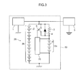
- Fig. 3 is a block diagram showing another configuration of the power supply system according to the present embodiment.
- the power supply system 50 comprises a generator 1, a cell assembly 20 and a control unit 70.
- the generator 1 is used for charging the cell assembly 20 and, for instance, is a generator that is mounted on a vehicle and having a constant voltage specification for generating power based on the rotary motion of the engine.
- an in-car device 5 Connected to the power supply system 50 is, as with the configuration of Fig. 1 , an in-car device 5 as an example of a load.
- the cell assembly 20 includes a first assembled battery 2a in which a plurality (four in the configuration of Fig. 3 ) of cells ⁇ (first cells) are connected in series and a second assembled battery 2b in which a plurality (twelve in the configuration of Fig. 3 ) of cells ⁇ (second cells) are connected in series, and the first assembled battery 2a and the second assembled battery 2b are connected in parallel.
- the resistor 3 is connected to the generator 1 side (in-car device 5 side) of the first assembled battery 2a in series, the charging current from the generator 1 is supplied to the first assembled battery 2a via the resistor 3.
- the current that is accumulated in the first assembled battery 2a is discharged to the in-car device 5 via the resistor 3.
- a charging current is randomly supplied from the generator 1 to the first assembled battery 2a and the second assembled battery 2b.
- a switch 6 is connected to the resistor 3 in parallel. Furthermore, a diode 8 is also connected to the resistor 3 in parallel. An anode of the diode 8 is connected to the positive electrode of the first assembled battery 2a, and its cathode is connected to the generator 1 and the in-car device 5, and the diode 8 has a function of supporting the resistor 3 and discharging the first assembled battery 2a.
- the switch 6 is provided for turning ON/OFF the connection between the first assembled battery 2a and the generator 1 and in-car device 5 based on a command from the control unit 70.
- the control unit 70 comprises an input unit 9 to which the voltage of the first assembled battery 2a measured with the voltage detecting circuit (voltage measurement unit) 7 is successively input, a storage unit (memory) 11 for storing the discharge end voltage Vs of the first assembled battery 2a, a switch control unit 10 for switching the ON/OFF of the switch 6 connecting the generator 1 and the in-car device 5 and first assembled battery 2a based on the measured voltage input to the input unit 9 and the discharge end voltage Vs read from the storage unit 11, and a control signal output unit 12 for outputting a control signal from the switch control unit 10 to the switch 6.
- the switch 6 a general switch such as a field effect transistor (FET) or a semiconductor switch may be used.
- the voltage detecting circuit 7 is configured, for example, using an AD (analog/digital) converter or a comparator for detecting the terminal voltage of the first assembled battery 2a.
- the switch control unit 10 performs control so as to keep the switch 6 in an ON state until the voltage of the first assembled battery 2a measured with the voltage detecting circuit 7 reaches the discharge end voltage Vs read from the storage unit 11. Thereby, the first assembled battery 2a can be discharged up to a predetermined state (discharge end voltage Vs) in a short period of time. Meanwhile, when the voltage of the first assembled battery 2a measured with the voltage detecting circuit 7 reaches the discharge end voltage Vs, the switch control unit 10 outputs a control signal to the switch 6 via the control signal output unit 12 for turning OFF the connection with the first assembled battery 2a. It is thereby possible to limit the discharge current and reduce the possibility of the first assembled battery 2a being over-discharged.
- the ratio V2/V1 of the average charging voltage V1 of the first assembled battery 2a and the average charging voltage V2 of the second assembled battery 2b is set within the range of 1.01 to 1.18. This is because, if the ratio V2/V1 is less than 1.01, the charging current from the generator 1 will easily flow to the second assembled battery 2b, and the first assembled battery 2a cannot be efficiently charged. Contrarily, if the ratio V2/V1 exceeds 1.18, the first assembled battery 2a will easily overcharge.
- the charge end voltage is manually set according to the characteristics of the active material that is used as the positive electrode or the negative electrode, but this is usually 4.2V. As shown in Fig. 2 , in the case of E in Fig. 2 in which the charge end voltage is 4.2V, the full charge capacity is 2550mAh. Here, the voltage (3.8V) at the point in time that the charging capacity is 1275mAh (half the charging capacity when charging 4.2V) will be the average charging voltage per nonaqueous electrolyte secondary battery.
- the cell is an alkaline storage battery such as a nickel hydride storage battery
- the characteristics of nickel hydroxide as the positive electrode active material the charging voltage will drop simultaneously with the completion of the full charge pursuant to the rise in temperature, and become a fully charged state.
- the voltage at the point in time of half the full charge capacity, which is the quantity of accumulated charge in a fully charged state, will be the average charging voltage of the alkaline storage battery.
- a nonaqueous electrolyte secondary battery such as a lithium ion secondary battery is used as in this embodiment.
- the nonaqueous electrolyte secondary battery has high energy density in comparison to an alkaline storage battery, and is preferable as the receiving end of the charging current in the power supply system 40 of the present invention.
- a nonaqueous electrolyte secondary battery entails problems such as the electrolyte component decomposing under a high temperature environment, as a result of adopting the configuration of this embodiment in which a lateral flow circuit is used as the second assembled battery 2b in substitute for a resistor with significant heat generation, it is possible to easily prevent the problem of the cells deforming due to the rise in the atmospheric temperature of the cell assembly 20 (particularly the first assembled battery 2a as the primary power source).
- a nonaqueous electrolyte secondary battery with high energy density per unit weight can be used, without any problem, as the cells ⁇ configuring the first assembled battery 2a.
- lithium composite oxide containing cobalt is used as the active material of the positive electrode of the nonaqueous electrolyte secondary battery.
- the discharge voltage of the nonaqueous electrolyte secondary battery can be increased as a result of using lithium composite oxide containing cobalt such as lithium cobalt oxide as the active material of the positive electrode, and the energy density can be easily increased.
- the discharge end voltage Vs is set to be within a range of 2.2V to 3.7V per cell ⁇ . This is because, in the configuration of the power supply system 50 shown in Fig. 3 , if the discharge end voltage Vs is set to less than 2.2V when the switch 6 is turned ON and the first assembled battery 2a is discharged, this is not preferable since the cells ⁇ will become over-discharged.
- Fig. 5 shows another configuration example of the cell assembly according to this embodiment.
- the power supply system 60 of this embodiment comprises a cell assembly 20' in which a first assembled battery 2a' and a second assembled battery 2b' are connected in parallel.
- the first assembled battery 2a' is configured by additionally connecting in series two alkaline storage batteries having an average charging voltage of 1.4V as the cells ⁇ (third cells) to the three cells ⁇ , in which one cell ⁇ was reduced from the first assembled battery 2a in the configuration of the cell assembly 20 shown in Fig. 1 , that are connected in series.
- the second assembled battery 2b' is configured such that eleven cells ⁇ , in which one cell ⁇ was reduced from the second assembled battery 2b in the configuration of the cell assembly 20 shown in Fig. 1 and Fig. 3 , are connected in series.
- the average charging voltage V1 of the first assembled battery 2a' will be 14.2V
- the average charging voltage V2 of the second assembled battery 2b' will be 15.4V.
- the ratio V2/V1 of the average charging voltage V1 of the first assembled battery 2a' and the average charging voltage V2 of the second assembled battery 2b' can be set to be within the range of 1.01 to 1.18.
- the capacity of the cells ⁇ configuring the first assembled battery 2a' is greater than the capacity of the cells ⁇ .
- the forced discharge start voltage Va is provided so that the cell ⁇ will be near 4.0V per cell (that is, the forced discharge start voltage Va is an integral multiple of 4.0V)
- the rated voltage is 14.5V, and there is a problem in that it will not be an integral multiple of 4.0V, and a fraction (2.5V) will arise.
- the foregoing fraction can be dealt with by additionally connecting in series, as needed, a cell ⁇ (alkaline storage battery in which the average charging voltage is near 1.4V) to a plurality of cells ⁇ that are connected in series.
- the average charging voltage V1 of the first assembled battery 2a when using as the first assembled battery 2a configured by additionally connecting in series two nickel hydride storage batteries having an average charging voltage of 1.4V as the cells ⁇ to three lithium ion secondary batteries connected in series and having an average charging voltage of 3.8V as the cells ⁇ , the average charging voltage V1 of the first assembled battery 2a will be 14.2V.
- the nickel hydride storage battery as the cell ⁇ has a highly flat charging voltage (change of the terminal voltage in relation to the change of SOC is small). Specifically, in the case of a nickel hydride storage battery, the charging voltage will remain flat and hardly change even if the SOC rises due to the charge. Meanwhile, with a lithium ion storage battery, since the charging voltage will rise pursuant to the rise of the SOC due to the charge, the cell ⁇ (lithium ion secondary battery) will be charged to a predetermined voltage (3.9V).
- the foregoing flatness of the nickel hydride storage battery (charging voltage is flat and will hardly change during the charge regardless of the SOC) can be used to distribute the remaining 0.3V (value obtained by subtracting 14.2V as the average charging voltage V1 of the first assembled battery 2a from 14.5V as the rated voltage of the generator 1) to the charge of the three cells ⁇ . Consequently, the cells ⁇ (lithium ion secondary batteries) can be charged up to 3.9V per cell (73% based on SOC conversion).
- an alkaline storage battery (specifically, a nickel hydride storage battery having an average charging voltage of 1.4V per cell) is used as the cells ⁇ configuring the second assembled battery 2b.
- an alkaline storage battery entails a rise in temperature simultaneously with the completion of full charge as the characteristic of nickel hydroxide as the positive electrode active material, the oxygen overvoltage will drop and the charging voltage will also drop.
- a lateral flow circuit is used as the second assembled battery 2b in substitute for a resistor with significant heat generation, it is possible to easily prevent the problem of the cells deforming due to the rise in the atmospheric temperature of the cell assembly 20 (particularly the first assembled battery 2a as the primary power source).
- an alkaline storage battery can be used, without any problem, as the cell ⁇ with high energy density per unit weight configuring the second assembled battery 2b as the lateral flow circuit.
- the power supply system comprises: a cell assembly in which a first assembled battery, made up of a plurality of first cells connected in series, and a second assembled battery, made up of a plurality of second cells connected in series, are connected in parallel, and a generator for charging the cell assembly.
- the cell assembly is confiogured such that an average charging voltage V1 as a terminal voltage when the first assembled battery reaches a charging capacity that is half of a full charge capacity is set to be a voltage that is smaller than an average charging voltage V2 as a terminal voltage when the second assembled battery reaches a charging capacity that is half of a full charge capacity.
- a resistor is connected in series to the first assembled battery.
- an average charging voltage V1 of the first assembled battery is set to be a voltage that is smaller than an average charging voltage V2 of the second assembled battery.
- a resistor is connected in series to the first assembled battery.
- the charging voltage of the first assembled battery can be made to appear to be a large charging voltage.
- the difference (change in voltage sought based on the product of the resistance value and current of the resistor) of the charging voltage according to the charging current is added to the true voltage of the first assembled battery, the relation of the charging voltage will appear to be the opposite (first assembled battery > second assembled battery).
- the charging current from the generator will be preferentially supplied to the second assembled battery.
- an alkaline storage battery such as a nickel hydride storage battery or a nickel cadmium storage battery or a nonaqueous electrolyte secondary battery such as a lithium ion secondary battery or a lithium polymer secondary battery with high energy density per unit weight as the secondary battery
- a safe and secure power supply system capable of receiving all currents from the generator as a charging current while reducing the possibility of inducing problems such as the deformation of the secondary battery.
- the resistance value of the resistor is preferably set to be within the range of 30m ⁇ to 118m ⁇ per first cell.
- the resistance value of the resistor is set to less than 30m ⁇ , this is not preferably since the charge will be performed until the SOC of the first assembled battery becomes excessive. Meanwhile, if the resistance value of the resistor is contrarily set in excess of 118m ⁇ , this is not preferable since the charging current will be shut down in a stage where the quantity of charged electricity of the first assembled battery is insufficient.
- the foregoing configuration further comprises a voltage measurement unit that measures a voltage of the first assembled battery, a switch that is connected in parallel to the resistor and that switches ON/OFF the connection between the first assembled battery and the generator, and a control unit that switches the ON/OFF of the switch based on a measurement result of the voltage measurement unit, wherein the control unit performs control so as to turn ON the switch when detection is made that a voltage of the first assembled battery measured by the voltage measurement unit has dropped over time.
- a voltage measurement unit that measures a voltage of the first assembled battery
- a switch that is connected in parallel to the resistor and that switches ON/OFF the connection between the first assembled battery and the generator
- a control unit that switches the ON/OFF of the switch based on a measurement result of the voltage measurement unit, wherein the control unit performs control so as to turn ON the switch when detection is made that a voltage of the first assembled battery measured by the voltage measurement unit has dropped over time.
- control unit will perform control so as to turn ON the switch when detection is made that the voltage of the first assembled battery measured by the voltage measurement unit has dropped over time.
- the control unit will perform control so as to turn ON the switch when detection is made that the voltage of the first assembled battery measured by the voltage measurement unit has dropped over time.
- control unit performs control so as to turn OFF the switch when it detects that a voltage of the first assembled battery measured with the voltage measurement unit has reached a discharge end voltage Vs.
- the voltage accumulated in the first assembled battery is discharge via the resistor.
- the foregoing configuration further comprises a diode that is connected in parallel to the resistor, and a cathode is connected to the generator.
- a ratio V2/V1 of an average charging voltage V1 of the first assembled battery to an average charging voltage V2 of the second assembled battery is set within the range of 1.01 to 1.18.
- a nonaqueous electrolyte secondary battery such as a lithium ion secondary battery is used as the first cell configuring the first assembled battery as with the present embodiment.
- the nonaqueous electrolyte secondary battery has high energy density in comparison to an alkaline storage battery, and is preferable as the receiving end of the charging current in the power supply system.
- a nonaqueous electrolyte secondary battery entails problems such as the electrolyte component decomposing under a high temperature environment, as a result of adopting the configuration of this embodiment in which a lateral flow circuit is used as the second assembled battery in substitute for a resistor with significant heat generation, it is possible to prevent the problem of the cell deforming due to the rise in the atmospheric temperature of the cell assembly (particularly the first assembled battery as the primary power source).
- a nonaqueous electrolyte secondary battery with high energy density per unit weight can be used, without any problem, as the first cells configuring the first assembled battery.
- lithium composite oxide containing cobalt is used as an active material of a positive electrode of the nonaqueous electrolyte secondary battery. This is because the discharge voltage of the nonaqueous electrolyte secondary battery can be increased as a result of using lithium composite oxide containing cobalt such as lithium cobalt oxide as the active material of the positive electrode, and the energy density can be easily increased.
- the discharge end voltage Vs is set within the range of 2.2V to 3.7V per first cell.
- the first assembled battery is configured by a third cell of an alkaline storage battery being additionally connected in series to the plurality of first cells connected in series. Moreover, preferably, the capacity of the third cell is larger than the capacity of the first cell.
- the first assembled battery can be suitably combined to match the rated voltage of the generator so as to enable the charge without excess or deficiency.
- the reason why the foregoing range is preferably is because, while this is the same as the configuration of not comprising a third cell, it is possible to avoid the danger when the charging voltage of the first cells or the third cells configuring the first assembled battery becomes abnormally high. Moreover, sufficient safety can be ensured without having to measure and control the individual voltages of the first assembled battery.
- the forced discharge start voltage Va is provided so that the first cells will be near 4.0V per cell (that is, the forced discharge start voltage Va is an integral multiple of 4.0V)
- the rated voltage is 14.5V, and there is a problem in that it will not be an integral multiple of 4.0V, and a fraction (2.5V) will arise.
- the foregoing fraction can be dealt with by additionally connecting in series, as needed, a third cell (alkaline storage battery in which the average charging voltage is near 1.4V) to the plurality of first cells (first assembled battery) that are connected in series.
- the average charging voltage V1 of the first assembled battery when using as a first assembled battery configured by additionally connecting in series two nickel hydride storage batteries having an average charging voltage of 1.4V as the third cells to three lithium ion secondary batteries connected in series and having an average charging voltage of 3.8V as the first cells, the average charging voltage V1 of the first assembled battery will be 14.2V.
- the nickel hydride storage battery as the third cell has a highly flat charging voltage (change of the terminal voltage in relation to the change of SOC is small). Specifically, in the case of a nickel hydride storage battery, the charging voltage will remain flat and hardly change even if the SOC rises due to the charge. Meanwhile, with a lithium ion storage battery, since the charging voltage will rise pursuant to the rise of the SOC due to the charge, the cells (lithium ion secondary battery) will be charged to a predetermined voltage (3.9V).
- the foregoing flatness of the nickel hydride storage battery (charging voltage is flat and will hardly change during the charge regardless of the SOC) can be used to distribute the remaining 0.3V (value obtained by subtracting 14.2V as the average charging voltage V1 of the first assembled battery from 14.5V as the rated voltage of the generator) to the charge of the three first cells. Consequently, the first cells (lithium ion secondary batteries) can be charged up to 3.9V per cell (73% based on SOC conversion).
- an alkaline storage battery (specifically, a nickel hydride storage battery having an average charging voltage of 1.4V per cell) is used as the second cell configuring the second assembled battery.
- an alkaline storage battery entails a rise in temperature simultaneously with the completion of full charge as the characteristic of nickel hydroxide as the positive electrode active material, the oxygen overvoltage will drop and the charging voltage will also drop.
- a lateral flow circuit is used as the second assembled battery in substitute for a resistor with significant heat generation, it is possible to prevent the problem of the cell deforming due to the rise in the atmospheric temperature of the cell assembly.
- an alkaline storage battery with high energy density per unit weight can be used, without any problem, as the second cell configuring the second assembled battery as the lateral flow circuit.
- the foregoing example used a lithium ion secondary battery as the first cell (cell ⁇ ), similar results can be obtained even when using a lithium polymer secondary battery among the nonaqueous electrolyte secondary batteries in which the electrolyte is in the form of a gel.
- the foregoing example used a nickel hydride storage battery as the first cell, similar results were obtained when using a nickel cadmium storage battery or the like.
- the present invention is not limited to the foregoing embodiments, and may be suitably changed to the extent that it does not deviate from the gist of this invention. It goes without saying that the respective embodiments of the present invention may also be worked in combination.
- the power supply system of the present invention uses an assembled battery made up of nonaqueous electrolyte secondary batteries with a higher energy density per unit weight than lead storage batteries, the application potency of the present invention as a cell starter power supply of racing cars is high, and extremely effective.
Landscapes
- Engineering & Computer Science (AREA)
- Chemical & Material Sciences (AREA)
- Chemical Kinetics & Catalysis (AREA)
- Electrochemistry (AREA)
- General Chemical & Material Sciences (AREA)
- Manufacturing & Machinery (AREA)
- Power Engineering (AREA)
- Inorganic Chemistry (AREA)
- Secondary Cells (AREA)
- Charge And Discharge Circuits For Batteries Or The Like (AREA)
- Battery Mounting, Suspending (AREA)
- Direct Current Feeding And Distribution (AREA)
Abstract
The power supply system of this invention includes a cell assembly in which a first assembled battery, made up of a plurality of first cells connected in series, and a second assembled battery, made up of a plurality of second cells connected in series, are connected in parallel, and a generator that charges the cell assembly. The cell assembly is configured such that an average charging voltage V1 as a terminal voltage when the first assembled battery reaches a charging capacity that is half of a full charge capacity is set to be a voltage that is smaller than an average charging voltage V2 as a terminal voltage when the second assembled battery reaches a charging capacity that is half of a full charge capacity. In addition, a resistor is connected in series to the first assembled battery.
Description
- The present invention relates to a power supply system having a cell assembly in which a plurality of cells are combined, and more specifically relates to technology of causing the cell assembly to function as a power source without overcharging the cell as a secondary battery.
- An alkaline storage battery such as a nickel hydride storage battery and a nickel cadmium storage battery, and a nonaqueous electrolyte secondary battery such as a lithium ion secondary battery and a lithium polymer secondary battery have higher energy density per unit weight than a lead storage battery, and are attracting attention as a power source to be mounted on mobile objects such as vehicles and portable devices. In particular, if cells made up of a plurality of nonaqueous electrolyte secondary batteries are connected in series to configure a cell assembly with high energy density per unit weight, and mounted on a vehicle as a cell starter power supply (so-called power source that is not a drive source of the vehicle) in substitute for a lead storage battery, it is considered to be promising for use in races and the like.
- While a power source of vehicles is discharged with a large current as a cell starter during the start-up on the one hand, it is charged by receiving the current sent from a generator (constant voltage charger) while the vehicle is being driven. Although the lead storage battery has a reaction mechanism that is suitable for charge/discharge with a relatively large current, it cannot be said that the foregoing secondary batteries are suitable for charge/discharge with a large current from the perspective of their reaction mechanism. Specifically, the foregoing secondary batteries have the following drawbacks at the end stage of charging.
- Foremost, with an alkaline storage battery such as a nickel hydride storage battery or a nickel cadmium storage battery, oxygen gas is generated from the positive electrode at the end stage of charging, but when the atmospheric temperature becomes high, the charging voltage of the battery will drop pursuant to the drop in the voltage that generates oxygen gas from the positive electrode; that is, the oxygen overvoltage. If n-number of alkaline storage batteries in which the charging voltage of the batteries dropped to V1 are to be charged with a constant voltage charger (rated charging voltage V2) and the relation of V2 > nV1 is satisfied, the charge will not end and the oxygen gas will continue to be generated, and there is a possibility that the individual secondary batteries (cells) configuring the assembled battery will deform due to the rise in the inner pressure of the battery.
- With a nonaqueous electrolyte secondary battery such as a lithium ion secondary battery or a lithium polymer secondary battery, while the electrolytic solution containing a nonaqueous electrolyte tends to decompose at the end stage of charging, this tendency becomes prominent when the atmospheric temperature increases, and there is a possibility that the cells configuring the assembled battery will deform due to the rise in the inner pressure of the battery.
- In order to overcome the foregoing problems, as shown in
Patent Document 1, it would be effective to pass additional current from a separate circuit (lateral flow circuit) at the time that the charge of the assembled battery to be used as the power source is complete. - When diverting
Patent Document 1 to vehicle installation technology, the lateral flow circuit can be materialized as the following two modes. The first mode is the mode of configuring the lateral flow circuit in the form of supplying current to the other in-vehicle electrically powered equipment (lamp, car stereo, air conditioner and the like). The second mode is the mode of configuring the lateral flow circuit in the form of simply supplying current to a resistor that consumes current. - Nevertheless, when adopting the first mode, there is a possibility that the constant voltage charger will supply excessive current to the foregoing electrically powered equipment and cause the electrically powered equipment to malfunction. Moreover, when adopting the second mode, the heat that is generated when the resistor consumes the current will increase the atmospheric temperature of the foregoing secondary battery, and the possibility of the cell deforming cannot be resolved. Thus, even if a secondary battery with high energy density per unit weight is randomly used to configure the cell assembly, it is difficult to combine it with a constant voltage charger.
Patent Document 1: Japanese Patent Application Laid-open No.H07-059266 - An object of this invention is to provide a safe and secure power supply system that uses a secondary battery with high energy density per unit weight, and which is capable of easily inhibiting the deformation of such secondary battery even upon receiving all currents from a generator as a charging current.
- The power supply system according to one aspect of the present invention comprises: a cell assembly in which a first assembled battery, made up of a plurality of first cells connected in series, and a second assembled battery, made up of a plurality of second cells connected in series, are connected in parallel; and a generator that charges the cell assembly. The cell assembly is configured such that an average charging voltage V1 as a terminal voltage when the first assembled battery reaches a charging capacity that is half of a full charge capacity is set to be a voltage that is smaller than an average charging voltage V2 as a terminal voltage when the second assembled battery reaches a charging capacity that is half of a full charge capacity. In addition, a resistor is connected in series to the first assembled battery.
- According to the foregoing configuration, an average charging voltage V1 of the first assembled battery is set to be a voltage that is smaller than an average charging voltage V2 of the second assembled battery. Thereby, in a normal state (until reaching the forced discharge start voltage that is set to be slightly lower than the full charge voltage), the first assembled battery mainly receives the charging current from the generator, and, when the first assembled battery approaches full charge, the second assembled battery as the lateral flow circuit receives the charging current from the generator.
- Moreover, a resistor is connected in series to the first assembled battery. As a result of connecting a resistor to the first assembled battery in series, the charging voltage of the first assembled battery can be made to appear to be a large charging voltage. Specifically, since the difference (change in voltage sought based on the product of the resistance value and current of the resistor) of the charging voltage according to the charging current is added to the true voltage of the first assembled battery, the relation of the charging voltage will appear to be the opposite (first assembled battery > second assembled battery). After the relation of the charging voltage is reversed, the charging current from the generator will be preferentially supplied to the second assembled battery. Thereby, when a large charging current is generated, the SOC of the first assembled battery to which the foregoing reverse phenomenon will occur will shift to the lower side. Thus, it is possible to prevent the respective first cells configuring the first assembled battery from becoming overcharged.
- According to the foregoing configuration, since a resistor which is associated with excessive heat generation is not used, the atmospheric temperature of the cell assembly (particularly the first assembled battery as the primary power source) will not increase. Thus, it is possible to avoid the problem of the cell deforming due to heat.
- Accordingly, even when using an alkaline storage battery such as a nickel hydride storage battery or a nickel cadmium storage battery or a nonaqueous electrolyte secondary battery such as a lithium ion secondary battery or a lithium polymer secondary battery with high energy density per unit weight as the secondary battery, it is possible to realize a safe and secure power supply system capable of receiving all currents from the generator as a charging current while reducing the possibility of inducing problems such as the deformation of the secondary battery.
- In cases where it is necessary to constantly receive the charging current from the generator such as with a cell-starter power supply, the deformation of the secondary battery can be inhibited even if all currents from the generator are received as the charging current by adopting the power supply system of the present invention.
- The present invention is particularly effective when using a cell starter power supply that needs to constantly receive a charging current from the generator.
- The object, features and advantages of the present invention will become clearer based on the ensuing detailed explanation and attached drawings.
- [
Fig. 1] Fig. 1 is a block diagram explaining the configuration of a power supply system according to an embodiment of the present invention. - [
Fig. 2] Fig. 2 is a diagram showing the initial charge-discharge behavior of a lithium ion secondary battery as an example of a cell at a normal temperature. - [
Fig. 3] Fig. 3 is a block diagram explaining the configuration of a power supply system according to another embodiment of the present invention. - [
Fig.4] Fig. 4 is a functional block diagram of a power supply system according to an embodiment of the present invention. - [
Fig. 5] Fig. 5 is a block diagram explaining the configuration of a power supply system according to another embodiment of the present invention. - The best mode for carrying out the present invention is now explained with reference to the attached drawings.
-
Fig. 1 is a block diagram explaining the configuration of a power supply system according to an embodiment of the present invention. - As shown in
Fig. 1 , thepower supply system 40 comprises agenerator 1 and acell assembly 20. Thegenerator 1 is used for charging thecell assembly 20 and, for instance, is a generator that is mounted on a vehicle and having a constant voltage specification for generating power based on the rotary motion of the engine. Thecell assembly 20 includes a first assembledbattery 2a in which a plurality (four in the configuration ofFig. 1 ) of cells α (first cells) are connected in series and a second assembledbattery 2b in which a plurality (twelve in the configuration ofFig. 1 ) of cells β (second cells) are connected in series, and the first assembledbattery 2a and the second assembledbattery 2b are connected in parallel. A charging current is randomly supplied from thegenerator 1 to the first assembledbattery 2a and the second assembledbattery 2b. - In this embodiment, the configuration is such that a
resistor 3 is connected in series to a terminal (positive electrode) on thegenerator 1 side of the first assembledbattery 2a, and the charging current from thegenerator 1 is supplied to thegenerator 1 via theresistor 3. Connected to thepower supply system 40 is an in-car device 5 as an example of a load. The in-car device 5 is, for example, a load device such as a cell starter for starting the vehicle engine, lights, car navigation system or the like. The positive electrode of the first assembledbattery 2a is connected to the in-car device 5 via theresistor 3, and the discharge current of the first assembledbattery 2a is supplied to the in-car device 5 via theresistor 3. - The resistance value of the
resistor 3 is preferably set to be within the range of 30mΩ to 118mΩ per cell α. - A case of using a generator of a constant voltage specification as the
generator 1, using a lithium ion secondary battery, which is an example of a nonaqueous electrolyte secondary battery, as the cell α constituting a first assembledbattery 2a, and using an alkaline storage battery (specifically a nickel hydride storage battery) as the cell β is now explained in detail. -
Fig. 2 is a diagram showing the charge behavior in the case of charging, with a generator of a constant voltage specification, a lithium ion secondary battery using lithium cobalt oxide as the positive electrode active material and using graphite as the negative electrode active material. InFig. 2 , a graph showing a case where the voltage Ve (terminal voltage of each cell) in which the rated voltage of thegenerator 1 is distributed per lithium ion battery (cell) is 3.8V is represented with symbol A, a graph showing a case of 3.9V is represented with symbol B, a graph showing a case of 4.0V is represented with symbol C, a graph showing a case of 4.1V is represented with symbol D, and a graph showing a case of 4.2V is represented with symbol E. - As shown in
Fig. 2 , in the case where the voltage Ve is 3.8V (shown with symbol A inFig. 2 ), the current is constant from the charge start up to approximately 33 minutes, and the voltage is thereafter constant. In the case where the voltage Ve is 3.9V (shown with symbol B inFig. 2 ), the current is constant from the charge start up to approximately 41 minutes, and the voltage is thereafter constant. In the case where the voltage Ve is 4.0V (shown with symbol C inFig. 2 ), the current is constant from the charge start up to approximately 47 minutes, and the voltage is thereafter constant. In the case where the voltage Ve is 4.1V (shown with symbol D inFig. 2 ), the current is constant from the charge start up to approximately 53 minutes, and the voltage is thereafter constant. In the case where the voltage Ve is 4.2V (shown with symbol E inFig. 2 ), the current is constant from the charge start up to approximately 57 minutes, and the voltage is thereafter constant. - The
generator 1 is configured so as to charge the cells α (lithium ion secondary battery) with a constant current until reaching the voltage Ve, and perform constant voltage charge to the lithium ion secondary battery while attenuating the current. For example, if the rated voltage is 3.9V (shown with symbol B inFig. 2 ), the state of charge (SOC: State of Charge) (value obtained by dividing the charging capacity having a voltage Ve of 3.9V by the charging capacity having a voltage Ve of 4.2V) will be 73%. Meanwhile, if the voltage Ve of thegenerator 1 is 4.1V per lithium ion secondary battery (shown with symbol D inFig. 2 ), the SOC will be 91%. Table 1 show the relation between the rated voltage and the SOC based onFig. 2 . -
[Table 1] Rated voltage (V) per cell 4.2 4.15 4.1 4.05 4.0 3.95 3.9 3.85 3.8 SOC (%) 100 95.5 91 86.5 82 77.5 73 68.5 64 - With the lithium ion secondary battery, when the SOC after charge approaches 100%, the component (primarily carbonate) of the electrolytic solution containing a nonaqueous electrolyte will easily decompose. Thus, in order to avoid a charging current from additionally being supplied from the
generator 1 to the lithium ion secondary battery in a state where the SOC is close to 100%, a large charging current will not flow to the first assembledbattery 2a due to the function of theresistor 3, and such charging current will preferentially flow to the second assembledbattery 2b. - Specifically, if the charging current increases, the voltage drop of the
resistor 3 will also increase. Then, since the total of the voltage drop and the terminal voltage of the first assembledbattery 2a will also increase, the amount of current to be distributed to the second assembled battery will also increase. - The specific operation of the
power supply system 40 according to this embodiment is now explained. - In a low SOC range, the average charging voltage V1 of the first assembled
battery 2a is smaller than the average charging voltage V2 of the second assembledbattery 2b. Thus, the charging current from thegenerator 1 will be preferentially supplied to the first assembledbattery 2a if the current value of the charging current does not become excessively large. - Here, since the flatness of the charging voltage of the nickel hydride storage battery of the cells β is high, the charging voltage of the second assembled
battery 2b will not increase drastically even if the SOC approaches 100%. Meanwhile, since the flatness of the charging voltage of the lithium ion secondary battery as the cell α is low, upon approaching full charge (SOC 100%), the charging voltage of the first assembledbattery 2a will increase drastically pursuant to the rise of the SOC. Specifically, even if the average charging voltage V1 of the first assembledbattery 2a is set to be smaller than the average charging voltage V2 of the second assembledbattery 2b, if the SOC approaches 100%, the charging voltage of the first assembledbattery 2a will become larger than the charging voltage of the second assembledbattery 2b. - If the lithium ion secondary battery as the cell α is charged with a large current, the charging voltage will rise and result in an overcharge, and, in addition to considerable deterioration in performance, the reliability may also be impaired. In order to prevent the foregoing problems, as shown in
Fig. 1 , the present embodiment connects theresistor 3 having an appropriate resistance value to the first assembledbattery 2a in series. The charging voltage of the first assembledbattery 2a will thereby appear to be a large charging voltage. - Specifically, since the difference (change in voltage sought based on the product of the resistance value and current of the resistor 3) of the charging voltage according to the charging current is added to the true voltage of the first assembled
battery 2a, the relation of the charging voltage will appear to be the opposite (first assembledbattery 2a > second assembledbattery 2b). After the relation of the charging voltage is reversed, the charging current from thegenerator 1 will be preferentially supplied to the second assembledbattery 2b. - According to the foregoing configuration, when a large charging current is generated, the SOC to which the foregoing reverse phenomenon will occur will shift to the lower side. Thus, it is possible to prevent the lithium ion secondary battery configuring the first assembled
battery 2a from becoming overcharged. - Incidentally, a charging current is not constantly flowing from the
generator 1 to the first assembledbattery 2a or the second assembledbattery 2b. For example, during braking or the like, the first assembledbattery 2a and the second assembledbattery 2b are contrarily discharged toward the in-car device 5, and enter a state of being able to receive the charging current from thegenerator 1 once again. - The configuration of the
power supply system 40 can be simplified by realizing the foregoing relation between the average charging voltage V1 of the first assembledbattery 2a and the average charging voltage V2 of the second assembledbattery 2b. - For example, in the configuration of
Fig. 1 , if an alkaline storage battery (specifically, a nickel hydride storage battery having an average charging voltage of 1.4V per cell) is used as the cell β of the second assembledbattery 2b, the average charging voltage V2 of the second assembledbattery 2b made up of twelve cells β will be 16.8V. Meanwhile, the average charging voltage V1 of the first assembledbattery 2a made up of four lithium ion secondary batteries (average charging voltage of 3.8V per cell) will be a value of 15.2V. Thus, the ratio V2/V1 of the average charging voltage V1 of the first assembledbattery 2a and the average charging voltage V2 of the second assembledbattery 2b will be 1.11. Under normal circumstances, since thegenerator 1 is of a constant voltage specification, as a result of setting the average charging voltage V1 of the first assembledbattery 2a to be smaller than the average charging voltage V2 of the second assembledbattery 2b as with the foregoing mode, it is possible to configure a safe and securepower supply system 40 that is able to receive all currents from thegenerator 1 as a charging current while inhibiting the deformation of the secondary battery without having to use any complicated means for transforming one of the assembled batteries (for example, means for causing the V2/V1 to become approximately 1.1 by using a DC/DC converter on one of the assembled batteries). -
Fig. 3 is a block diagram showing another configuration of the power supply system according to the present embodiment. - As shown in
Fig. 3 , thepower supply system 50 comprises agenerator 1, acell assembly 20 and acontrol unit 70. Thegenerator 1 is used for charging thecell assembly 20 and, for instance, is a generator that is mounted on a vehicle and having a constant voltage specification for generating power based on the rotary motion of the engine. - Connected to the
power supply system 50 is, as with the configuration ofFig. 1 , an in-car device 5 as an example of a load. - The
cell assembly 20 includes a first assembledbattery 2a in which a plurality (four in the configuration ofFig. 3 ) of cells α (first cells) are connected in series and a second assembledbattery 2b in which a plurality (twelve in the configuration ofFig. 3 ) of cells β (second cells) are connected in series, and the first assembledbattery 2a and the second assembledbattery 2b are connected in parallel. Here, since theresistor 3 is connected to thegenerator 1 side (in-car device 5 side) of the first assembledbattery 2a in series, the charging current from thegenerator 1 is supplied to the first assembledbattery 2a via theresistor 3. The current that is accumulated in the first assembledbattery 2a is discharged to the in-car device 5 via theresistor 3. A charging current is randomly supplied from thegenerator 1 to the first assembledbattery 2a and the second assembledbattery 2b. - Moreover, a
switch 6 is connected to theresistor 3 in parallel. Furthermore, adiode 8 is also connected to theresistor 3 in parallel. An anode of thediode 8 is connected to the positive electrode of the first assembledbattery 2a, and its cathode is connected to thegenerator 1 and the in-car device 5, and thediode 8 has a function of supporting theresistor 3 and discharging the first assembledbattery 2a. Theswitch 6 is provided for turning ON/OFF the connection between the first assembledbattery 2a and thegenerator 1 and in-car device 5 based on a command from thecontrol unit 70. - The specific operation of the
power supply system 50 is now explained with reference to the functional block diagram ofFig. 4 . - As shown with the functional block diagram of
Fig. 4 , thecontrol unit 70 comprises aninput unit 9 to which the voltage of the first assembledbattery 2a measured with the voltage detecting circuit (voltage measurement unit) 7 is successively input, a storage unit (memory) 11 for storing the discharge end voltage Vs of the first assembledbattery 2a, aswitch control unit 10 for switching the ON/OFF of theswitch 6 connecting thegenerator 1 and the in-car device 5 and first assembledbattery 2a based on the measured voltage input to theinput unit 9 and the discharge end voltage Vs read from thestorage unit 11, and a controlsignal output unit 12 for outputting a control signal from theswitch control unit 10 to theswitch 6. As theswitch 6, a general switch such as a field effect transistor (FET) or a semiconductor switch may be used. Thevoltage detecting circuit 7 is configured, for example, using an AD (analog/digital) converter or a comparator for detecting the terminal voltage of the first assembledbattery 2a. - The
switch control unit 10 performs control so as to keep theswitch 6 in an ON state until the voltage of the first assembledbattery 2a measured with thevoltage detecting circuit 7 reaches the discharge end voltage Vs read from thestorage unit 11. Thereby, the first assembledbattery 2a can be discharged up to a predetermined state (discharge end voltage Vs) in a short period of time. Meanwhile, when the voltage of the first assembledbattery 2a measured with thevoltage detecting circuit 7 reaches the discharge end voltage Vs, theswitch control unit 10 outputs a control signal to theswitch 6 via the controlsignal output unit 12 for turning OFF the connection with the first assembledbattery 2a. It is thereby possible to limit the discharge current and reduce the possibility of the first assembledbattery 2a being over-discharged. - Preferably, the ratio V2/V1 of the average charging voltage V1 of the first assembled
battery 2a and the average charging voltage V2 of the second assembledbattery 2b is set within the range of 1.01 to 1.18. This is because, if the ratio V2/V1 is less than 1.01, the charging current from thegenerator 1 will easily flow to the second assembledbattery 2b, and the first assembledbattery 2a cannot be efficiently charged. Contrarily, if the ratio V2/V1 exceeds 1.18, the first assembledbattery 2a will easily overcharge. - The method of calculating the average charging voltage is now explained.
- If the cell is a nonaqueous electrolyte secondary battery such as a lithium ion secondary battery, the charge end voltage is manually set according to the characteristics of the active material that is used as the positive electrode or the negative electrode, but this is usually 4.2V. As shown in
Fig. 2 , in the case of E inFig. 2 in which the charge end voltage is 4.2V, the full charge capacity is 2550mAh. Here, the voltage (3.8V) at the point in time that the charging capacity is 1275mAh (half the charging capacity when charging 4.2V) will be the average charging voltage per nonaqueous electrolyte secondary battery. Meanwhile, if the cell is an alkaline storage battery such as a nickel hydride storage battery, as the characteristics of nickel hydroxide as the positive electrode active material, the charging voltage will drop simultaneously with the completion of the full charge pursuant to the rise in temperature, and become a fully charged state. The voltage at the point in time of half the full charge capacity, which is the quantity of accumulated charge in a fully charged state, will be the average charging voltage of the alkaline storage battery. - As the cells α configuring the first assembled
battery 2a, preferably, a nonaqueous electrolyte secondary battery such as a lithium ion secondary battery is used as in this embodiment. - This is because the nonaqueous electrolyte secondary battery has high energy density in comparison to an alkaline storage battery, and is preferable as the receiving end of the charging current in the
power supply system 40 of the present invention. Although a nonaqueous electrolyte secondary battery entails problems such as the electrolyte component decomposing under a high temperature environment, as a result of adopting the configuration of this embodiment in which a lateral flow circuit is used as the second assembledbattery 2b in substitute for a resistor with significant heat generation, it is possible to easily prevent the problem of the cells deforming due to the rise in the atmospheric temperature of the cell assembly 20 (particularly the first assembledbattery 2a as the primary power source). Thus, a nonaqueous electrolyte secondary battery with high energy density per unit weight can be used, without any problem, as the cells α configuring the first assembledbattery 2a. - Moreover, when using a nonaqueous electrolyte secondary battery as the cell α, preferably, lithium composite oxide containing cobalt is used as the active material of the positive electrode of the nonaqueous electrolyte secondary battery.
- This is because the discharge voltage of the nonaqueous electrolyte secondary battery can be increased as a result of using lithium composite oxide containing cobalt such as lithium cobalt oxide as the active material of the positive electrode, and the energy density can be easily increased.
- Preferably, the discharge end voltage Vs is set to be within a range of 2.2V to 3.7V per cell α. This is because, in the configuration of the
power supply system 50 shown inFig. 3 , if the discharge end voltage Vs is set to less than 2.2V when theswitch 6 is turned ON and the first assembledbattery 2a is discharged, this is not preferable since the cells α will become over-discharged. Contrarily, if the discharge end voltage Vs is set in excess of 3.7V, this is not preferable since the discharge quantity of electricity of the cell α of the first assembledbattery 2a per charge will be insufficient and the first assembledbattery 2a will quickly reach the discharge end voltage and cannot be discharged when the equipment-side needs a large current, and because only the second assembledbattery 2b will be frequently discharged repeatedly. -
Fig. 5 shows another configuration example of the cell assembly according to this embodiment. As shown inFig. 5 , thepower supply system 60 of this embodiment comprises acell assembly 20' in which a first assembledbattery 2a' and a second assembledbattery 2b' are connected in parallel. The first assembledbattery 2a' is configured by additionally connecting in series two alkaline storage batteries having an average charging voltage of 1.4V as the cells γ (third cells) to the three cells α, in which one cell α was reduced from the first assembledbattery 2a in the configuration of thecell assembly 20 shown inFig. 1 , that are connected in series. The second assembledbattery 2b' is configured such that eleven cells β, in which one cell β was reduced from the second assembledbattery 2b in the configuration of thecell assembly 20 shown inFig. 1 andFig. 3 , are connected in series. - According to the foregoing configuration, the average charging voltage V1 of the first assembled
battery 2a' will be 14.2V, and the average charging voltage V2 of the second assembledbattery 2b' will be 15.4V. Consequently, the ratio V2/V1 of the average charging voltage V1 of the first assembledbattery 2a' and the average charging voltage V2 of the second assembledbattery 2b' can be set to be within the range of 1.01 to 1.18. Here, preferably, the capacity of the cells γ configuring the first assembledbattery 2a' is greater than the capacity of the cells α. - As described above, with the
power supply system 40 of this embodiment, when using a nonaqueous electrolyte secondary battery as the cell α, if the forced discharge start voltage Va is provided so that the cell α will be near 4.0V per cell (that is, the forced discharge start voltage Va is an integral multiple of 4.0V), this is preferable since a margin can be set for the full charge (SOC = 100%, charge end voltage 4.2V). Nevertheless, if a multi-purpose generator based on a lead storage battery specification is to be used as thegenerator 1, the rated voltage is 14.5V, and there is a problem in that it will not be an integral multiple of 4.0V, and a fraction (2.5V) will arise. Thus, the foregoing fraction can be dealt with by additionally connecting in series, as needed, a cell γ (alkaline storage battery in which the average charging voltage is near 1.4V) to a plurality of cells α that are connected in series. - Specifically, as described above, when using as the first assembled
battery 2a configured by additionally connecting in series two nickel hydride storage batteries having an average charging voltage of 1.4V as the cells γ to three lithium ion secondary batteries connected in series and having an average charging voltage of 3.8V as the cells α, the average charging voltage V1 of the first assembledbattery 2a will be 14.2V. Here, the nickel hydride storage battery as the cell γ has a highly flat charging voltage (change of the terminal voltage in relation to the change of SOC is small). Specifically, in the case of a nickel hydride storage battery, the charging voltage will remain flat and hardly change even if the SOC rises due to the charge. Meanwhile, with a lithium ion storage battery, since the charging voltage will rise pursuant to the rise of the SOC due to the charge, the cell α (lithium ion secondary battery) will be charged to a predetermined voltage (3.9V). - Thus, if the capacity of the cell γ is set to be greater than the capacity of the cell α, the foregoing flatness of the nickel hydride storage battery (charging voltage is flat and will hardly change during the charge regardless of the SOC) can be used to distribute the remaining 0.3V (value obtained by subtracting 14.2V as the average charging voltage V1 of the first assembled
battery 2a from 14.5V as the rated voltage of the generator 1) to the charge of the three cells α. Consequently, the cells α (lithium ion secondary batteries) can be charged up to 3.9V per cell (73% based on SOC conversion). - Moreover, as in the foregoing example, preferably, an alkaline storage battery (specifically, a nickel hydride storage battery having an average charging voltage of 1.4V per cell) is used as the cells β configuring the second assembled
battery 2b. - Since an alkaline storage battery entails a rise in temperature simultaneously with the completion of full charge as the characteristic of nickel hydroxide as the positive electrode active material, the oxygen overvoltage will drop and the charging voltage will also drop. However, according to the configuration of this embodiment in which a lateral flow circuit is used as the second assembled
battery 2b in substitute for a resistor with significant heat generation, it is possible to easily prevent the problem of the cells deforming due to the rise in the atmospheric temperature of the cell assembly 20 (particularly the first assembledbattery 2a as the primary power source). Thus, an alkaline storage battery can be used, without any problem, as the cell β with high energy density per unit weight configuring the second assembledbattery 2b as the lateral flow circuit. - As described above, the power supply system according to one aspect of the present invention comprises: a cell assembly in which a first assembled battery, made up of a plurality of first cells connected in series, and a second assembled battery, made up of a plurality of second cells connected in series, are connected in parallel, and a generator for charging the cell assembly. The cell assembly is confiogured such that an average charging voltage V1 as a terminal voltage when the first assembled battery reaches a charging capacity that is half of a full charge capacity is set to be a voltage that is smaller than an average charging voltage V2 as a terminal voltage when the second assembled battery reaches a charging capacity that is half of a full charge capacity. In addition, a resistor is connected in series to the first assembled battery.
- According to the foregoing configuration, an average charging voltage V1 of the first assembled battery is set to be a voltage that is smaller than an average charging voltage V2 of the second assembled battery. Thereby, in a normal state (until reaching the forced discharge start voltage that is set to be slightly lower than the full charge voltage), the first assembled battery mainly receives the charging current from the generator, and, when the first assembled battery approaches full charge, the second assembled battery as the lateral flow circuit receives the charging current from the generator.
- Moreover, a resistor is connected in series to the first assembled battery. As a result of connecting a resistor to the first assembled battery in series, the charging voltage of the first assembled battery can be made to appear to be a large charging voltage. Specifically, since the difference (change in voltage sought based on the product of the resistance value and current of the resistor) of the charging voltage according to the charging current is added to the true voltage of the first assembled battery, the relation of the charging voltage will appear to be the opposite (first assembled battery > second assembled battery). After the relation of the charging voltage is reversed, the charging current from the generator will be preferentially supplied to the second assembled battery. Thereby, when a large charging current is generated, the SOC of the first assembled battery to which the foregoing reverse phenomenon will occur will shift to the lower side. Thus, it is possible to prevent the respective first cells configuring the first assembled battery from becoming overcharged.
- According to the foregoing configuration, since a resistor which is associated with excessive heat generation is not used, the atmospheric temperature of the cell assembly (particularly the first assembled battery as the primary power source) will not increase. Thus, it is possible to avoid the problem of the cell deforming due to heat.
- Accordingly, even when using an alkaline storage battery such as a nickel hydride storage battery or a nickel cadmium storage battery or a nonaqueous electrolyte secondary battery such as a lithium ion secondary battery or a lithium polymer secondary battery with high energy density per unit weight as the secondary battery, it is possible to realize a safe and secure power supply system capable of receiving all currents from the generator as a charging current while reducing the possibility of inducing problems such as the deformation of the secondary battery.
- In the foregoing configuration, the resistance value of the resistor is preferably set to be within the range of 30mΩ to 118mΩ per first cell.
- If the resistance value of the resistor is set to less than 30mΩ, this is not preferably since the charge will be performed until the SOC of the first assembled battery becomes excessive. Meanwhile, if the resistance value of the resistor is contrarily set in excess of 118mΩ, this is not preferable since the charging current will be shut down in a stage where the quantity of charged electricity of the first assembled battery is insufficient.
- Preferably, the foregoing configuration further comprises a voltage measurement unit that measures a voltage of the first assembled battery, a switch that is connected in parallel to the resistor and that switches ON/OFF the connection between the first assembled battery and the generator, and a control unit that switches the ON/OFF of the switch based on a measurement result of the voltage measurement unit, wherein the control unit performs control so as to turn ON the switch when detection is made that a voltage of the first assembled battery measured by the voltage measurement unit has dropped over time.
- According to the foregoing configuration, the control unit will perform control so as to turn ON the switch when detection is made that the voltage of the first assembled battery measured by the voltage measurement unit has dropped over time. Thereby, when the voltage drop of the first assembled battery over time (start of discharge) is detected, the first assembled battery can be discharged via the switch to a predetermined state in a short period of time.
- In the foregoing configuration, preferably, the control unit performs control so as to turn OFF the switch when it detects that a voltage of the first assembled battery measured with the voltage measurement unit has reached a discharge end voltage Vs.
- According to the foregoing configuration, after the measured voltage of the first assembled battery reaches a discharge end voltage Vs, the voltage accumulated in the first assembled battery is discharge via the resistor. Thus, it is possible to reduce the possibility of the first assembled battery being over-discharged.
- Preferably, the foregoing configuration further comprises a diode that is connected in parallel to the resistor, and a cathode is connected to the generator.
- In the foregoing configuration, preferably, a ratio V2/V1 of an average charging voltage V1 of the first assembled battery to an average charging voltage V2 of the second assembled battery is set within the range of 1.01 to 1.18.
- This is because, if the ratio V2/V1 is less than 1.01, the charging current from the generator will easily flow to the second assembled battery, and the first assembled battery cannot be efficiently charged. Contrarily, if the ratio V2/V1 exceeds 1.18, the first assembled battery will easily overcharge.
- Preferably, a nonaqueous electrolyte secondary battery such as a lithium ion secondary battery is used as the first cell configuring the first assembled battery as with the present embodiment.
- This is because the nonaqueous electrolyte secondary battery has high energy density in comparison to an alkaline storage battery, and is preferable as the receiving end of the charging current in the power supply system. Although a nonaqueous electrolyte secondary battery entails problems such as the electrolyte component decomposing under a high temperature environment, as a result of adopting the configuration of this embodiment in which a lateral flow circuit is used as the second assembled battery in substitute for a resistor with significant heat generation, it is possible to prevent the problem of the cell deforming due to the rise in the atmospheric temperature of the cell assembly (particularly the first assembled battery as the primary power source). Thus, a nonaqueous electrolyte secondary battery with high energy density per unit weight can be used, without any problem, as the first cells configuring the first assembled battery.
- If a nonaqueous electrolyte secondary battery is used as the first cell, preferably, lithium composite oxide containing cobalt is used as an active material of a positive electrode of the nonaqueous electrolyte secondary battery. This is because the discharge voltage of the nonaqueous electrolyte secondary battery can be increased as a result of using lithium composite oxide containing cobalt such as lithium cobalt oxide as the active material of the positive electrode, and the energy density can be easily increased.
- In the foregoing configuration, preferably, the discharge end voltage Vs is set within the range of 2.2V to 3.7V per first cell.
- This is because, if the discharge end voltage Vs is set to less than 2.2V in use of the switch and the first assembled battery is discharged, this is not preferable since the first cells will become over-discharged. Contrarily, if the discharge end voltage Vs is set in excess of 3.7V, this is not preferable since the discharge quantity of electricity per first cell of the first assembled battery will be insufficient and the first assembled battery will quickly reach the discharge end voltage and cannot be discharged when the equipment-side needs a large current, and because only the second assembled battery will be frequently discharged repeatedly.
- In the foregoing configuration, preferably, the first assembled battery is configured by a third cell of an alkaline storage battery being additionally connected in series to the plurality of first cells connected in series. Moreover, preferably, the capacity of the third cell is larger than the capacity of the first cell.
- According to the foregoing configuration, the first assembled battery can be suitably combined to match the rated voltage of the generator so as to enable the charge without excess or deficiency. Thus, if the range of the forced discharge start voltage Va is set to the foregoing range, the reason why the foregoing range is preferably is because, while this is the same as the configuration of not comprising a third cell, it is possible to avoid the danger when the charging voltage of the first cells or the third cells configuring the first assembled battery becomes abnormally high. Moreover, sufficient safety can be ensured without having to measure and control the individual voltages of the first assembled battery.
- As described above, with the power supply system of this embodiment, when using a nonaqueous electrolyte secondary battery as the first cells, if the forced discharge start voltage Va is provided so that the first cells will be near 4.0V per cell (that is, the forced discharge start voltage Va is an integral multiple of 4.0V), this is preferable since a margin can be set for the full charge (SOC = 100%, charge end voltage 4.2V). Nevertheless, if a multi-purpose generator based on a lead storage battery specification is to be used as the generator, the rated voltage is 14.5V, and there is a problem in that it will not be an integral multiple of 4.0V, and a fraction (2.5V) will arise. Thus, the foregoing fraction can be dealt with by additionally connecting in series, as needed, a third cell (alkaline storage battery in which the average charging voltage is near 1.4V) to the plurality of first cells (first assembled battery) that are connected in series.
- Specifically, as described above, when using as a first assembled battery configured by additionally connecting in series two nickel hydride storage batteries having an average charging voltage of 1.4V as the third cells to three lithium ion secondary batteries connected in series and having an average charging voltage of 3.8V as the first cells, the average charging voltage V1 of the first assembled battery will be 14.2V. Here, the nickel hydride storage battery as the third cell has a highly flat charging voltage (change of the terminal voltage in relation to the change of SOC is small). Specifically, in the case of a nickel hydride storage battery, the charging voltage will remain flat and hardly change even if the SOC rises due to the charge. Meanwhile, with a lithium ion storage battery, since the charging voltage will rise pursuant to the rise of the SOC due to the charge, the cells (lithium ion secondary battery) will be charged to a predetermined voltage (3.9V).
- Thus, if the capacity of the third cell is set to be greater than the capacity of the first cell, the foregoing flatness of the nickel hydride storage battery (charging voltage is flat and will hardly change during the charge regardless of the SOC) can be used to distribute the remaining 0.3V (value obtained by subtracting 14.2V as the average charging voltage V1 of the first assembled battery from 14.5V as the rated voltage of the generator) to the charge of the three first cells. Consequently, the first cells (lithium ion secondary batteries) can be charged up to 3.9V per cell (73% based on SOC conversion).
- In the foregoing configuration, preferably, an alkaline storage battery (specifically, a nickel hydride storage battery having an average charging voltage of 1.4V per cell) is used as the second cell configuring the second assembled battery.
- Since an alkaline storage battery entails a rise in temperature simultaneously with the completion of full charge as the characteristic of nickel hydroxide as the positive electrode active material, the oxygen overvoltage will drop and the charging voltage will also drop. However, according to the configuration of this invention in which a lateral flow circuit is used as the second assembled battery in substitute for a resistor with significant heat generation, it is possible to prevent the problem of the cell deforming due to the rise in the atmospheric temperature of the cell assembly. Thus, an alkaline storage battery with high energy density per unit weight can be used, without any problem, as the second cell configuring the second assembled battery as the lateral flow circuit.
- Although the foregoing example used a lithium ion secondary battery as the first cell (cell α), similar results can be obtained even when using a lithium polymer secondary battery among the nonaqueous electrolyte secondary batteries in which the electrolyte is in the form of a gel. Moreover, although the foregoing example used a nickel hydride storage battery as the first cell, similar results were obtained when using a nickel cadmium storage battery or the like.
- The present invention is not limited to the foregoing embodiments, and may be suitably changed to the extent that it does not deviate from the gist of this invention. It goes without saying that the respective embodiments of the present invention may also be worked in combination.
- Since the power supply system of the present invention uses an assembled battery made up of nonaqueous electrolyte secondary batteries with a higher energy density per unit weight than lead storage batteries, the application potency of the present invention as a cell starter power supply of racing cars is high, and extremely effective.
Claims (12)
- A power supply system, comprising:a cell assembly in which a first assembled battery, made up of a plurality of first cells connected in series, and a second assembled battery, made up of a plurality of second cells connected in series, are connected in parallel; anda generator that charges the cell assembly, whereinthe cell assembly is configured such that an average charging voltage V1 as a terminal voltage when the first assembled battery reaches a charging capacity that is half of a full charge capacity is set to be a voltage that is smaller than an average charging voltage V2 as a terminal voltage when the second assembled battery reaches a charging capacity that is half of a full charge capacity, anda resistor is connected in series to the first assembled battery.
- The power supply system according to claim 1, wherein a resistance value of the resistor is set within a range of 30mΩ to 118mΩ for each of the plurality of first cells.
- The power supply system according to claim 1 or claim 2, further comprising:a voltage measurement unit that measures a voltage of the first assembled battery;a switch that is connected in parallel to the resistor and that switches ON/OFF a connection between the first assembled battery and the generator; anda control unit that switches ON/OFF of the switch based on a measurement result of the voltage measurement unit, whereinthe control unit performs control so as to turn ON the switch when determination is made that a voltage of the first assembled battery measured by the voltage measurement unit has dropped over time.
- The power supply system according to claim 3, wherein the control unit performs control so as to turn OFF the switch when determination is made that a voltage of the first assembled battery measured by the voltage measurement unit has reached a discharge end voltage Vs.
- The power supply system according to any one of claims 1 to 4, further comprising a diode that is connected in parallel to the resistor, wherein
a cathode is connected to the generator. - The power supply system according to any one of claims 1 to 5, wherein a ratio V2/V1 of an average charging voltage V1 of the first assembled battery to an average charging voltage V2 of the second assembled battery is set within a range of 1.01 to 1.18.
- The power supply system according to any one of claims 1 to 6, wherein the first cell is a nonaqueous electrolyte secondary battery.
- The power supply system according to claim 7,
wherein lithium composite oxide containing cobalt is used as an active material of a positive electrode of the nonaqueous electrolyte secondary battery. - The power supply system according to claim 7 or claim 8, wherein the discharge end voltage Vs is set within a range of 3.85V to 3.95V for each of the plurality of first cells.
- The power supply system according to claim 7 or claim 8, wherein the first assembled battery is configured by a third cell of an alkaline storage battery further connected in series to the plurality of first cells connected in series.
- The power supply system according to claim 10, wherein a capacity of the third cell is larger than a capacity of the first cell.
- The power supply system according to any one of claims 1 to 11, wherein an alkaline storage battery is used as the second cell.
Applications Claiming Priority (2)
| Application Number | Priority Date | Filing Date | Title |
|---|---|---|---|
| JP2007259596A JP2009089569A (en) | 2007-10-03 | 2007-10-03 | Power system |
| PCT/JP2008/002531 WO2009044511A1 (en) | 2007-10-03 | 2008-09-12 | Power supply system |
Publications (1)
| Publication Number | Publication Date |
|---|---|
| EP2211399A1 true EP2211399A1 (en) | 2010-07-28 |
Family
ID=40525944
Family Applications (1)
| Application Number | Title | Priority Date | Filing Date |
|---|---|---|---|
| EP08834737A Withdrawn EP2211399A1 (en) | 2007-10-03 | 2008-09-12 | Power supply system |
Country Status (6)
| Country | Link |
|---|---|
| US (1) | US20100225276A1 (en) |
| EP (1) | EP2211399A1 (en) |
| JP (1) | JP2009089569A (en) |
| KR (1) | KR20100061754A (en) |
| CN (1) | CN101816082A (en) |
| WO (1) | WO2009044511A1 (en) |
Cited By (1)
| Publication number | Priority date | Publication date | Assignee | Title |
|---|---|---|---|---|
| EP2647102A4 (en) * | 2010-11-29 | 2016-11-02 | Martin Koebler | LITHIUM STARTER BATTERY AND SEMICONDUCTOR SWITCH FOR SAID BATTERY |
Families Citing this family (13)
| Publication number | Priority date | Publication date | Assignee | Title |
|---|---|---|---|---|
| DE102010043690A1 (en) * | 2010-11-10 | 2012-05-10 | Continental Automotive Gmbh | Method of distributing energy in an electric vehicle and electric vehicle |
| JP5891604B2 (en) * | 2011-04-28 | 2016-03-23 | トヨタ自動車株式会社 | Battery system |
| JP5386556B2 (en) | 2011-08-03 | 2014-01-15 | 株式会社日立製作所 | Battery system |
| US9577469B2 (en) * | 2011-12-16 | 2017-02-21 | Samsung Sdi Co., Ltd. | Battery pack |
| DE102012200804A1 (en) * | 2012-01-20 | 2013-07-25 | Continental Automotive Gmbh | On-board network and method for operating a vehicle electrical system |
| JP5925755B2 (en) * | 2013-12-20 | 2016-05-25 | プライムアースEvエナジー株式会社 | Battery module adjustment method and battery module adjustment apparatus |
| JP6237425B2 (en) * | 2014-04-09 | 2017-11-29 | トヨタ自動車株式会社 | vehicle |
| US10377389B2 (en) * | 2017-03-08 | 2019-08-13 | Ford Global Technologies, Llc | Load management to extend electric vehicle range |
| JP6823885B2 (en) * | 2017-11-07 | 2021-02-03 | Connexx Systems株式会社 | Combined battery, automobile and railway regenerative power storage device equipped with it |
| DE102019112552A1 (en) * | 2019-05-14 | 2020-11-19 | HELLA GmbH & Co. KGaA | Battery for a motor vehicle, motor vehicle and method for charging a battery |
| FR3115737B1 (en) * | 2020-11-02 | 2025-02-21 | Commissariat Energie Atomique | Power supply system |
| CN112421732B (en) * | 2020-11-30 | 2023-03-24 | 杭州智仝科技有限公司 | Energy storage method and system based on heterogeneous battery architecture |
| US20240154446A1 (en) * | 2021-03-10 | 2024-05-09 | Honda Motor Co., Ltd. | Electric power device, and control method for same |
Family Cites Families (5)
| Publication number | Priority date | Publication date | Assignee | Title |
|---|---|---|---|---|
| JPH0759266A (en) * | 1993-08-17 | 1995-03-03 | Toshiba Corp | Secondary battery charging circuit |
| US6274950B1 (en) * | 1994-03-03 | 2001-08-14 | American Power Conversion | Battery communication system |
| JPH08265987A (en) * | 1995-03-20 | 1996-10-11 | Integuran Kk | Series battery charging voltage distribution device |
| JP2004112900A (en) * | 2002-09-18 | 2004-04-08 | Nissan Motor Co Ltd | Power generation control device for vehicles |
| JP2009080939A (en) * | 2007-09-25 | 2009-04-16 | Panasonic Corp | Power supply system and battery assembly control method |
-
2007
- 2007-10-03 JP JP2007259596A patent/JP2009089569A/en active Pending
-
2008
- 2008-09-12 WO PCT/JP2008/002531 patent/WO2009044511A1/en not_active Ceased
- 2008-09-12 CN CN200880110502A patent/CN101816082A/en active Pending
- 2008-09-12 EP EP08834737A patent/EP2211399A1/en not_active Withdrawn
- 2008-09-12 US US12/681,272 patent/US20100225276A1/en not_active Abandoned
- 2008-09-12 KR KR1020107009505A patent/KR20100061754A/en not_active Withdrawn
Non-Patent Citations (1)
| Title |
|---|
| See references of WO2009044511A1 * |
Cited By (1)
| Publication number | Priority date | Publication date | Assignee | Title |
|---|---|---|---|---|
| EP2647102A4 (en) * | 2010-11-29 | 2016-11-02 | Martin Koebler | LITHIUM STARTER BATTERY AND SEMICONDUCTOR SWITCH FOR SAID BATTERY |
Also Published As
| Publication number | Publication date |
|---|---|
| US20100225276A1 (en) | 2010-09-09 |
| WO2009044511A1 (en) | 2009-04-09 |
| KR20100061754A (en) | 2010-06-08 |
| JP2009089569A (en) | 2009-04-23 |
| CN101816082A (en) | 2010-08-25 |
Similar Documents
| Publication | Publication Date | Title |
|---|---|---|
| EP2211399A1 (en) | Power supply system | |
| EP2207235A1 (en) | Power supply system and cell assembly control method | |
| EP2211416A1 (en) | Power supply system and cell assembly control method | |
| EP2190101A1 (en) | Power supply system | |
| EP2157657A1 (en) | Power system and assembled battery controlling method | |
| EP2058918B1 (en) | Hybrid power source | |
| US7427450B2 (en) | Hybrid fuel cell system with battery capacitor energy storage system | |
| US6781343B1 (en) | Hybrid power supply device | |
| ES2873750T3 (en) | Hybrid battery system | |
| JP5571129B2 (en) | Hybrid power system | |
| US20110181245A1 (en) | Unitized charging and discharging battery management system and programmable battery management module thereof | |
| US9754732B2 (en) | Energy storage arrangement | |
| KR20140014226A (en) | Charge balancing system for batteries | |
| CN101675555A (en) | Battery pack and battery system | |
| US20130249493A1 (en) | Vehicle and method of controlling the same | |
| US10833352B2 (en) | Vehicle having a lithium-ion battery | |
| US20180233929A1 (en) | Battery to battery charger using asymmetric batteries | |
| JP4724726B2 (en) | DC power supply system and charging method thereof | |
| US20220416564A1 (en) | Integration Of Batteries and Super-Capacitors In A Vehicular Power Supply System | |
| CN216671738U (en) | Balance management system applied to battery module | |
| JP5409424B2 (en) | Power supply | |
| US12483061B2 (en) | Battery pack | |
| CN211075605U (en) | High voltage power management system | |
| CN107978810A (en) | A kind of traction accumulator bag | |
| JP2019213333A (en) | Battery monitoring device |
Legal Events
| Date | Code | Title | Description |
|---|---|---|---|
| PUAI | Public reference made under article 153(3) epc to a published international application that has entered the european phase |
Free format text: ORIGINAL CODE: 0009012 |
|
| 17P | Request for examination filed |
Effective date: 20100414 |
|
| AK | Designated contracting states |
Kind code of ref document: A1 Designated state(s): AT BE BG CH CY CZ DE DK EE ES FI FR GB GR HR HU IE IS IT LI LT LU LV MC MT NL NO PL PT RO SE SI SK TR |
|
| AX | Request for extension of the european patent |
Extension state: AL BA MK RS |
|
| DAX | Request for extension of the european patent (deleted) | ||
| STAA | Information on the status of an ep patent application or granted ep patent |
Free format text: STATUS: THE APPLICATION HAS BEEN WITHDRAWN |
|
| 18W | Application withdrawn |
Effective date: 20121009 |