EP2211188A2 - Test probe with retractable insulative sleeve - Google Patents
Test probe with retractable insulative sleeve Download PDFInfo
- Publication number
- EP2211188A2 EP2211188A2 EP09170227A EP09170227A EP2211188A2 EP 2211188 A2 EP2211188 A2 EP 2211188A2 EP 09170227 A EP09170227 A EP 09170227A EP 09170227 A EP09170227 A EP 09170227A EP 2211188 A2 EP2211188 A2 EP 2211188A2
- Authority
- EP
- European Patent Office
- Prior art keywords
- insulative
- length
- insulative sleeve
- probe
- test probe
- Prior art date
- Legal status (The legal status is an assumption and is not a legal conclusion. Google has not performed a legal analysis and makes no representation as to the accuracy of the status listed.)
- Granted
Links
Images
Classifications
-
- G—PHYSICS
- G01—MEASURING; TESTING
- G01R—MEASURING ELECTRIC VARIABLES; MEASURING MAGNETIC VARIABLES
- G01R1/00—Details of instruments or arrangements of the types included in groups G01R5/00 - G01R13/00 and G01R31/00
- G01R1/02—General constructional details
- G01R1/06—Measuring leads; Measuring probes
- G01R1/067—Measuring probes
- G01R1/06788—Hand-held or hand-manipulated probes, e.g. for oscilloscopes or for portable test instruments
-
- H—ELECTRICITY
- H01—ELECTRIC ELEMENTS
- H01R—ELECTRICALLY-CONDUCTIVE CONNECTIONS; STRUCTURAL ASSOCIATIONS OF A PLURALITY OF MUTUALLY-INSULATED ELECTRICAL CONNECTING ELEMENTS; COUPLING DEVICES; CURRENT COLLECTORS
- H01R11/00—Individual connecting elements providing two or more spaced connecting locations for conductive members which are, or may be, thereby interconnected, e.g. end pieces for wires or cables supported by the wire or cable and having means for facilitating electrical connection to some other wire, terminal, or conductive member, blocks of binding posts
- H01R11/11—End pieces or tapping pieces for wires, supported by the wire and for facilitating electrical connection to some other wire, terminal or conductive member
- H01R11/18—End pieces terminating in a probe
Definitions
- This invention relates generally to test instrument lead probes, and more specifically one or more embodiments relate to test probes having adjustable length probe tips.
- Test instruments such as multimeters, voltage meters, oscilloscopes and the like, are used to measure electrical parameters in various electrical devices.
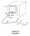
- Figure 1 illustrates an exemplary test instrument 100.
- the test instrument 100 has a test probe 102 that is coupled to an input/output 104 of the test instrument 100.
- the test probe 102 has a test lead 106 having a first end 108 that is coupled to the input/output 104 of the test instrument 100 and a second end 110 that is coupled to a probe body 112.
- the probe body 112 includes a tip 114, which is coupled to a test point (not shown) of a device (not shown) to be measured or tested.
- a second test probe (not shown), such as a ground connector, may be coupled to input/output 105.
- test probe tips are used in various test applications.
- various test probe assemblies having different probe tip lengths were used with test instruments.
- a user may have two sets of test probes, one probe set with long length probe tips and another set with short probe tips.
- Another method for accommodating for the need of different length probes has been to use probe tips that are removable from the probe holder or body.
- probe tips that are removable from the probe holder or body.
- both of these solutions require a user to have to manage two sets of test probes, either the entire test probe assembly or test probe tips.
- test points are located in an obstructed location and having multiple test probes or probe tips can result in problems for the user when switching out the different probes. For instance, the user may have difficulty carrying the extra probes or the equipment may put the user in an awkward position so that it is a challenge to change out the probes. Additionally, by having separate test probes, the user may misplace, drop, or lose the probes so that the appropriate probe or probe tip is not available when needed.
- test probes have been designed with probe tips that are slideable within the probe holder or body.
- the probe tip slides in and out of the probe body and is locked into position at a desired length.
- a locking mechanism that holds the probe tip within the probe body may be released so that the probe tip is free to move within the probe body.
- a user may then slide the probe tip so that a greater portion of the probe tip is exposed from the probe body and lock the probe tip into position. Therefore, rather than replacing the probe assembly or the probe tip, a single probe tip may act as a varying length probe tip.
- a single probe tip provides versatility and a user does not need to carry around probes having varying lengths.
- This standard specifies requirements for test probe tips for various test applications.
- the safety standard specifies the length of the exposed metal tip of the probe used in industrial applications, referred to as category III (CAT III) and category IV (CAT IV) installation, must be less than 4 mm in length.
- the probe tip for low energy applications, such as used in household applications or category II (CAT II) installations, must be less than 18 mm in length.
- Having a probe tip with exposed metal 18 mm in length is important because this allows users to easily insert the probe tip into a standard wall socket for quick and accurate measurement, which is not possible with a 4 mm probe tip.
- a reduced probe tip of 4 mm is important to help reduce risk of arcs and arc flash hazards, which is not an issue in CAT II environments.
- a user when using a slideable probe tip described above, a user will not know whether the exposed length of the probe tip is within the specified length to meet the safety standard unless a measurement is made on the exposed length of the probe tip each time the probe tip length is adjusted. This requires a user to carry a measurement tool and results in a time consuming second step. Although a user may expose a portion of the probe tip that is significantly less than required by the safety standards discussed above and not have to make a measurement, most applications require the entire amount allowed under the safety standard. For instance, in household application, a user will need a probe tip to be very close to the 18 mm maximum length because it will allow the user to insert the probe tip into standard wall sockets.
- test probe having an adjustable length probe tip that indexes to predetermined lengths. Additionally, there is a need for an adjustable probe tip that communicates to a user the length of the exposed probe tip.
- a test probe includes a conductive member having a main section and a first end, the first end being defined by an electrically conductive tip.
- the test probe further includes an insulative member surrounding a portion of the main section of the conductive member.
- the test probe further includes an insulative sleeve positioned between the insulative member and the conductive member. The insulative sleeve may be mechanically coupled to the insulative member to cause axial movement of the insulative sleeve relative to the conductive member.
- a test probe in another aspect of the invention, includes an insulative member having an opening at a first end. An inner surface of the insulative member includes at least one protrusion.
- the test probe further includes an insulative sleeve positioned within the opening of the insulative member. The insulative sleeve has at least one slot aligned with a respective one of the at least one protrusion.
- the test probe further includes a conductive member extending from a first end of the insulative sleeve.
- the conductive member has an electrically conductive tip defining a first end.
- Another aspect of the invention includes a method for adjusting a length of a probe tip exposed from an insulative component.
- the method includes providing a first length of the insulative sleeve extending from the test probe, and altering the length of the insulative sleeve extending from the test probe from the first length to a second length by physical characteristics in the test probe.
- the second length being a specific distance from the first length.
- a test probe comprising:
- the mechanical coupling includes a protrusion on an inner surface of the insulative member aligned with a slot on the insulative sleeve.
- test probe of the preceding paragraph wherein rotating the insulative member causes the protrusion to move the insulative sleeve from a first position to a second position.
- the slot has a first recess at a first end and a second recess at a second end.
- test probe of the preceding paragraph wherein when the protrusion is positioned in the first recess or the second recess, a greater force is required to rotate the insulative member relative to the insulative sleeve than when the protrusion is positioned in the slot.
- the insulative member has an opening aligned with a label portion on a second insulative member, the label portion describing the length of the conductive member that is exposed from an end of the insulative sleeve or the category safety rating for the length of the conductive member that is exposed from the end of the insulative sleeve.
- a test probe comprising:
- test probe of the preceding paragraph wherein rotating the insulative member relative to the insulative sleeve causes the insulative sleeve to slide relative to the conductive member.
- test probe of one of the preceding paragraphs wherein the at least one slot is a helix.
- the helix includes a first recess at a first end and a second recess at a second end.
- test probe of the preceding paragraph wherein the insulative sleeve locks relative to the conductive member when the at least one protrusion is positioned within the respective first or second recess.
- a first length of the conductive member extends from the insulative sleeve when the at least one protrusion is positioned in the first recess and a second length of the conductive member is exposed from the insulative sleeve when the at least one protrusion is positioned in the second recess, the first length being a specific distance from the second length.
- the insulative member includes a label portion describing an characteristic of the conductive member extending from the insulative sleeve when the protrusion is positioned in the first detent.
- the insulative member includes a label portion describing a category rating for the length of the conductive member exposed from the insulative sleeve when the protrusion is positioned in the first detent.
- a method for adjusting a length of a probe tip exposed from an insulative sleeve in a test probe comprising:
- the method of the preceding paragraph further comprising indicating that the length of the probe tip exposed from the insulative sleeve is less than a particular length.
- the physical characteristics in the test probe that alter the length of the insulative sleeve extending from the test probe includes a protrusion on an inner surface of the first insulative material that travels along a helix on an outer surface of the second insulative material.
- Embodiments of the present invention are directed toward test probes used with test and measurement equipment, and more particularly, one or more embodiments relate to test probes with probe tips having lengths that are indexable to at least two positions.
- a test probe includes a retractable insulative sleeve that indexes to a plurality of positions.
- the insulative sleeve may be indexed using a mechanical system, an optical system, or any combination thereof.
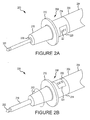
- FIGS 2A and 2B are schematic drawings of a test probe 200 according to one embodiment of the invention.
- the test probe 200 in Figures 2A and 2B includes a probe tip 202 and a probe body 204.
- the probe tip 202 is made from an electrically conductive material, and is configured to be placed in electrical communication with a test point (not shown) of an electrical device (not shown).
- the probe body 204 is made from an insulative material.
- the probe body 204 and the probe tip 202 are configured to be coupled to a test lead (not shown).
- the test lead is configured to be coupled to an input/output of a test instrument (not shown).
- the probe body 204 includes a handle portion 206 and a top portion 208.
- the handle portion 206 may be coupled to the test lead.
- the top portion 208 may include a nose 210, a finger guard 212, and a collar 214 or any combination thereof.
- the collar 214 of the top portion 208 is mechanically coupled to the handle portion 206 of the probe body 204. This coupling may be a press fit, snap fit, threaded coupling or any other mechanical coupling now known or later developed.
- An insulative sleeve 216 is positioned within the probe body 204 and extends from the nose 210 of the top portion 208. However, if the top portion 208 only includes a collar 214, the insulative sleeve would extend directly from the collar 214.
- the insulative sleeve 216 is made from an insulative material.
- the probe tip 202 extends from the insulative sleeve 216. In some embodiments, the probe tip 202 remains stationary within the probe body 204. However, the insulative sleeve 216 is extendable and retractable from the probe body 204.
- the insulative sleeve 216 is retracted into the top portion 208 of the probe body 204.
- the insulative sleeve 216 extends from the top portion 208 of the probe body 204 so that the insulative sleeve 216 surrounds a portion of the probe tip 202.
- Figures 2A and 2B when the insulative sleeve 216 is retracted into the top portion 208 of the probe body 204, more of the probe tip 202 is exposed then when the insulative sleeve 216 is extending from the top portion 208 of the probe body 204.
- the insulative sleeve 216 extends and retracts from the nose 210 of the top portion 208 when the top portion 208 of the probe body 204 is rotated relative to the handle portion 206. By rotating the top portion 208 in a first direction the insulative sleeve 216 extends from the top portion 208. Conversely, by rotating the top portion 208 in a second direction, such as a direction opposite the first direction, the insulative sleeve 216 retracts into the probe body 204. Additionally, and in the embodiment shown in Figures 2A and 2B , the collar 214 of the top portion 208 of the probe body 204 may include an opening 220.
- the opening 220 may be aligned with a label 221 to communicate the length of the exposed probe tip 202 or the category rating that the length of the probe tip 202 is qualified for under the safety standards discussed above.
- the label 221 may be aligned with a first label when the insulative sleeve 216 is fully retracted into the probe body 204 as is shown in Figure 2A and aligned with a second label when the insulative sleeve 216 is fully extended from the probe body 204 as is shown in Figure 2B .
- the label 221 communicates to a user the length of the probe tip 202 exposed from the insulative sleeve 216.
- This label 221 may be a visual element or a physical element.
- the label 221 may indicate the category rating the length is rated for or the actual length of the exposed probe tip 202.
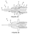
- Figures 3A and 3B are cross sectional schematic drawings of a test probe 300 comprising a test probe tip 202, an insulative sleeve 216, a top portion 208, and a handle portion 206 of a probe body according to one embodiment of the invention.
- the top portion 208 of the probe body includes a nose 210, a finger guard 212, and a collar 214 as described in reference to Figures 2A and 2B .
- an inner surface of the top portion 208 includes two protrusions or pins 222 and 224.
- the insulative sleeve includes two helices 226 and 228, which in the embodiment shown are cut outs along the surface of the insulative sleeve 216.
- the protrusions 222 and 224 on the inner surface of the top portion 208 are positioned so that as the top portion 208 is rotated in a first direction, the protrusions 222 and 224 guide the movement of the insulative sleeve 216 by moving along the respective helices 226 and 228, thus, causing the insulative sleeve 216 to extend from the top portion 208 of the probe as is shown in the test probe 300 in Figure 3A .
- the pins 222 and 224 guide the movement of the insulative sleeve 216 causing the insulative sleeve 216 to retract into the top portion 208 of the probe as is shown in Figure 3B .
- top portion having two pins.
- the top portion may have only one pin or more than two pins to guide the movement of the insulative sleeve.
- the insulative sleeve may have one helix.
- the top portion 208 may be rotated in the same direction to extend and retract the probe tip 202.
- the top portion 208 may be rotated in a first direction to extend the probe tip 202 and rotated in the opposite direction to retract the probe tip 202.
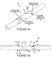
- FIG 4A is an isometric schematic drawing of an insulative sleeve 217 according to one embodiment of the invention.
- the insulative sleeve 217 is designed to be used with a single pin.
- the insulative sleeve 217 includes a helix 226 having a main section 230, a first end 232, and a second end 234.
- the first end 232 of the helix 226 has a first detent or first lock position 236 and the second end 234 of the helix 226 has a second detent or second lock position 238.
- a pin is positioned in either the first or second detent 236 and 238, the pin is moved out of the main section 230 of the helix 226.
- FIG. 4B is an isometric schematic drawing of an insulative sleeve 216 according to another embodiment of the invention.
- the insulative sleeve 216 includes two helices 226 and 228. Each helix 226 and 228 has a main section 230, a first end 232 of the helix, a second end 234 of the helix, a first detent 236 and a second detent 238.
- FIG. 3A the pins 222 and 224 are latched in a respective second detent 238.
- the insulative sleeve 216 is fully extended and insulates a portion of the probe tip 202 that extends from the top portion 208 of the probe body.
- the exposed length of the probe tip 202 is the length that extends from the insulative sleeve 216.
- a rotational force may be applied to the top portion 208 to cause the pins 222 and 224 to enter a respective second end 234 of the helices 226 and 228.
- the top portion 208 of the probe body may be further rotated to cause the pins 222 and 224 to guide the insulative sleeve 216 to move along the main section 230 of the helices 226 and 228.
- the insulative sleeve 216 retracts into the top portion 208 of the probe body.
- the pins 222 and 224 move along the respective main section 230 of the helices 226 and 228 until the pins 222 and 224 reach the first end 232 of the helices 226 and 228.
- the pins 222 and 224 are positioned in the first detent 236.
- the rotation force required to move the pins 222 and 224 from the first detent to the first end of the helix is generally greater than the rotation force required to move the pin along the main section of the helix.
- the rotational force required to move the pin from the second detent to the second end of the helix is generally greater than the rotation force required to move the pin along the main section of the helix. Therefore, when the pin is positioned in either the first detent or the second detent, the insulative sleeve is latched into a respective position.
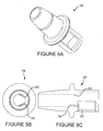
- Figure 5A is an isometric schematic drawing of the top portion 208 shown in Figures 3A and 3B .
- Figure 5B is cross sectional schematic drawing of the top portion in Figure 5A.
- Figure 5C is an schematic drawing of the top portion in Figure 5A .
- the top portion 208 includes two pins 222 and 224. As discussed above, the two pins 222 and 224 are configured to be positioned so that they are aligned with the helices 226 and 228 on the insulative sleeve 216. Additionally, the top portion 208 further includes an opening 220 to be aligned with a label.
- the label communicates the length of the exposed probe tip 202 or the category rating that the length of the probe tip 202 is qualified for under the safety standards discussed above. For instance, in one embodiment when the insulative sleeve 216 is fully extending from the nose 210 so that the pins 222 and 224 are positioned in the first detents 236, a first label may be aligned with the opening 220. Conversely, when the insulative sleeve 216 is retracted into the nose 210 so that the pins 222 and 224 are positioned in the second detents 238, a second label may be aligned with the opening 220. The first and second labels may be positioned on any appropriate device that is operable to be aligned with the opening 220.
- the labels are positioned on a portion of the probe body 204. In another embodiment, the labels are positioned on a portion of the insulative sleeve 216. As stated above, each label indicates to a user which category rating the length of the exposed part of the probe tip is rated for.
- the insulative sleeve may be indexable to a plurality of positions.
- the insulative sleeve may have a first and second detent coupled together by a first main helix as described above, but also a third detent coupled to the second detent by a second main helix. Therefore, the insulative sleeve would be able to latch into a third position, when the pin is positioned in the third detent. This third position would result in a third length of the probe tip extending from the top portion of the probe body.
- the insulative sleeve may extend to a third position in which the insulative sleeve completely covers the probe tip.
- any means of communication may be used to communicate to a user that the probe tip or the insulative sleeve has been indexed, such as a visual element, an audio element, or a raised surface on the label portion that a user can feel to determine the length of the exposed probe tip or the category rating. Any method of latching the insulative sleeve into a particular position may be used. Such modifications are well within the skill of those ordinarily skilled in the art. Accordingly, the invention is not limited except as by the appended claims.
Landscapes
- Physics & Mathematics (AREA)
- General Physics & Mathematics (AREA)
- Measuring Leads Or Probes (AREA)
Abstract
Description
- This invention relates generally to test instrument lead probes, and more specifically one or more embodiments relate to test probes having adjustable length probe tips.
- Test instruments, such as multimeters, voltage meters, oscilloscopes and the like, are used to measure electrical parameters in various electrical devices.
Figure 1 illustrates anexemplary test instrument 100. Thetest instrument 100 has atest probe 102 that is coupled to an input/output 104 of thetest instrument 100. Thetest probe 102 has atest lead 106 having afirst end 108 that is coupled to the input/output 104 of thetest instrument 100 and asecond end 110 that is coupled to aprobe body 112. Theprobe body 112 includes atip 114, which is coupled to a test point (not shown) of a device (not shown) to be measured or tested. As will be clear to a person having ordinary skill in the art, a second test probe (not shown), such as a ground connector, may be coupled to input/output 105. - In general, different length test probe tips are used in various test applications. In the past, to accommodate the need for different length probe tips, various test probe assemblies having different probe tip lengths were used with test instruments. For instance, a user may have two sets of test probes, one probe set with long length probe tips and another set with short probe tips. Another method for accommodating for the need of different length probes has been to use probe tips that are removable from the probe holder or body. Thus, rather than replacing the entire probe assembly, only the probe tip needs to be replaced. However, both of these solutions require a user to have to manage two sets of test probes, either the entire test probe assembly or test probe tips. Often test points are located in an obstructed location and having multiple test probes or probe tips can result in problems for the user when switching out the different probes. For instance, the user may have difficulty carrying the extra probes or the equipment may put the user in an awkward position so that it is a challenge to change out the probes. Additionally, by having separate test probes, the user may misplace, drop, or lose the probes so that the appropriate probe or probe tip is not available when needed.
- More recently, however, test probes have been designed with probe tips that are slideable within the probe holder or body. Thus, rather than replacing the entire probe assembly when a different length probe tip is required, the probe tip slides in and out of the probe body and is locked into position at a desired length. For instance, when a longer probe tip is required, a locking mechanism that holds the probe tip within the probe body may be released so that the probe tip is free to move within the probe body. A user may then slide the probe tip so that a greater portion of the probe tip is exposed from the probe body and lock the probe tip into position. Therefore, rather than replacing the probe assembly or the probe tip, a single probe tip may act as a varying length probe tip. When a long probe length is needed, the probe tip slides out of the probe body so that more of the probe tip extends from the probe body. When a short probe length is needed, some of the exposed probe tip slides back into the probe body so that less of the probe tip extends from the probe body. Consequently, a single probe tip provides versatility and a user does not need to carry around probes having varying lengths.
- Recently safety standards have been developed that limit the length of the exposed probe tip. In particular, the International Electrotechnical Commission (IEC), under the guidance of Technical Committee (TC66), generated a safety standard for Test and Measurement Equipment related to test probes referenced as IEC-61010-031. This standard specifies requirements for test probe tips for various test applications. For instance, the safety standard specifies the length of the exposed metal tip of the probe used in industrial applications, referred to as category III (CAT III) and category IV (CAT IV) installation, must be less than 4 mm in length. The probe tip for low energy applications, such as used in household applications or category II (CAT II) installations, must be less than 18 mm in length. Having a probe tip with exposed metal 18 mm in length is important because this allows users to easily insert the probe tip into a standard wall socket for quick and accurate measurement, which is not possible with a 4 mm probe tip. For industrial applications (CAT III and CAT IV) where high energy exists, a reduced probe tip of 4 mm is important to help reduce risk of arcs and arc flash hazards, which is not an issue in CAT II environments.
- Therefore, when using a slideable probe tip described above, a user will not know whether the exposed length of the probe tip is within the specified length to meet the safety standard unless a measurement is made on the exposed length of the probe tip each time the probe tip length is adjusted. This requires a user to carry a measurement tool and results in a time consuming second step. Although a user may expose a portion of the probe tip that is significantly less than required by the safety standards discussed above and not have to make a measurement, most applications require the entire amount allowed under the safety standard. For instance, in household application, a user will need a probe tip to be very close to the 18 mm maximum length because it will allow the user to insert the probe tip into standard wall sockets.
- There is, therefore, a need for a test probe having an adjustable length probe tip that indexes to predetermined lengths. Additionally, there is a need for an adjustable probe tip that communicates to a user the length of the exposed probe tip.
- Embodiments of the present invention are directed toward test probes used with test and measurement equipment, and more particularly, one or more embodiments relate to test probes with probe tips having lengths that are indexable to at least two positions. In one aspect of the invention a test probe includes a conductive member having a main section and a first end, the first end being defined by an electrically conductive tip. The test probe further includes an insulative member surrounding a portion of the main section of the conductive member. The test probe further includes an insulative sleeve positioned between the insulative member and the conductive member. The insulative sleeve may be mechanically coupled to the insulative member to cause axial movement of the insulative sleeve relative to the conductive member.
- In another aspect of the invention a test probe includes an insulative member having an opening at a first end. An inner surface of the insulative member includes at least one protrusion. The test probe further includes an insulative sleeve positioned within the opening of the insulative member. The insulative sleeve has at least one slot aligned with a respective one of the at least one protrusion. The test probe further includes a conductive member extending from a first end of the insulative sleeve. The conductive member has an electrically conductive tip defining a first end.
- Another aspect of the invention includes a method for adjusting a length of a probe tip exposed from an insulative component. The method includes providing a first length of the insulative sleeve extending from the test probe, and altering the length of the insulative sleeve extending from the test probe from the first length to a second length by physical characteristics in the test probe. The second length being a specific distance from the first length.
- Embodiments of the invention also include aspects according to the following paragraphs:
- A test probe, comprising:
- a conductive member having a main section and a first end, the first end being defined by an electrically conductive tip;
- an insulative member surrounding a portion of the main section of the conductive member; and
- an insulative sleeve positioned between the insulative member and the conductive member, the insulative sleeve mechanically coupled to the insulative member to cause axial movement of the insulative sleeve relative to the conductive member.
- The test probe of the preceding paragraph wherein the mechanical coupling includes a protrusion on an inner surface of the insulative member aligned with a slot on the insulative sleeve.
- The test probe of the preceding paragraph wherein rotating the insulative member causes the protrusion to move the insulative sleeve from a first position to a second position.
- The test probe of one of the preceding paragraphs wherein the slot has a first recess at a first end and a second recess at a second end.
- The test probe of the preceding paragraph wherein when the protrusion is positioned in the first recess or the second recess, a greater force is required to rotate the insulative member relative to the insulative sleeve than when the protrusion is positioned in the slot.
- The test probe of one of the preceding paragraphs wherein the insulative member has an opening aligned with a label portion on a second insulative member, the label portion describing the length of the conductive member that is exposed from an end of the insulative sleeve or the category safety rating for the length of the conductive member that is exposed from the end of the insulative sleeve.
- A test probe, comprising:
- an insulative member having an opening at a first end, an inner surface of the insulative member including at least one protrusion;
- an insulative sleeve positioned within the opening of the insulative member, the insulative sleeve having at least one slot aligned with a respective one of the at least one protrusions;
- a conductive member extending from a first end of the insulative sleeve, the conductive member having an electrically conductive tip defining a first end.
- The test probe of the preceding paragraph wherein rotating the insulative member relative to the insulative sleeve causes the insulative sleeve to slide relative to the conductive member.
- The test probe of one of the preceding paragraphs wherein the at least one slot is a helix.
- The test probe of the preceding paragraph wherein the helix includes a first recess at a first end and a second recess at a second end.
- The test probe of the preceding paragraph wherein the insulative sleeve locks relative to the conductive member when the at least one protrusion is positioned within the respective first or second recess.
- The test probe of the preceding paragraph wherein a first length of the conductive member extends from the insulative sleeve when the at least one protrusion is positioned in the first recess and a second length of the conductive member is exposed from the insulative sleeve when the at least one protrusion is positioned in the second recess, the first length being a specific distance from the second length.
- The test probe of one of the preceding paragraphs wherein the insulative member includes a label portion describing an characteristic of the conductive member extending from the insulative sleeve when the protrusion is positioned in the first detent.
- The test probe of one of the preceding paragraphs wherein the insulative member includes a label portion describing a category rating for the length of the conductive member exposed from the insulative sleeve when the protrusion is positioned in the first detent.
- A method for adjusting a length of a probe tip exposed from an insulative sleeve in a test probe, comprising:
- providing a first length of the insulative sleeve extending from the test probe; and
- altering the length of the insulative sleeve extending from the test probe from the first length to a second length, the first and second lengths being determined by physical characteristics in the test probe.
- The method of the preceding paragraph wherein the act of altering the length of the insulative sleeve extending from the test probe comprises altering the length of the probe tip exposed from the insulative sleeve.
- The method of the preceding paragraph further comprising indicating that the length of the probe tip exposed from the insulative sleeve is less than a particular length.
- The method of one of the preceding paragraphs further comprising indicating that the length of the probe tip exposed from the insulative material meets a requirement for a particular application.
- The method of one of the preceding paragraphs wherein the act of altering the length of the insulative sleeve extending from the test probe comprises rotating a first insulative material relative to a second insulative material to cause the insulative sleeve to move axially relative to the probe tip.
- The method of the preceding paragraph wherein the physical characteristics in the test probe that alter the length of the insulative sleeve extending from the test probe includes a protrusion on an inner surface of the first insulative material that travels along a helix on an outer surface of the second insulative material.
-
-
Figure 1 is a schematic drawing of a test instrument in accordance with prior art. -
Figure 2A is a schematic drawing of a test probe according to one embodiment of the invention. -
Figure 2B is a schematic drawing of a test probe according to one embodiment of the invention. -
Figure 3A is a cross sectional schematic drawing of a test probe according to one embodiment of the invention. -
Figure 3B is a cross sectional schematic drawing of a test probe according to one embodiment of the invention. -
Figure 4A is an isometric schematic drawing of an insulative sleeve according to one embodiment of the invention. -
Figure 4B is an isometric schematic drawing of an insulative sleeve according to one embodiment of the invention. -
Figure 5A is an isometric schematic drawing of the top portion of the probe body according to one embodiment of the invention. -
Figure 5B is a cross sectional schematic drawing of the top portion of the probe body according to one embodiment of the invention. -
Figure 5C is an schematic drawing of the top portion of the probe body according to one embodiment of the invention. - Embodiments of the present invention are directed toward test probes used with test and measurement equipment, and more particularly, one or more embodiments relate to test probes with probe tips having lengths that are indexable to at least two positions. In some embodiments, a test probe includes a retractable insulative sleeve that indexes to a plurality of positions. The insulative sleeve may be indexed using a mechanical system, an optical system, or any combination thereof. Certain details are set forth below to provide a sufficient understanding of the embodiments of the invention. However, it will be clear to one skilled in the art that various embodiments of the invention may be practiced without these particular details.
-
Figures 2A and 2B are schematic drawings of atest probe 200 according to one embodiment of the invention. Thetest probe 200 inFigures 2A and 2B includes aprobe tip 202 and aprobe body 204. Theprobe tip 202 is made from an electrically conductive material, and is configured to be placed in electrical communication with a test point (not shown) of an electrical device (not shown). Theprobe body 204 is made from an insulative material. Theprobe body 204 and theprobe tip 202 are configured to be coupled to a test lead (not shown). The test lead is configured to be coupled to an input/output of a test instrument (not shown). - The
probe body 204 includes ahandle portion 206 and atop portion 208. Thehandle portion 206 may be coupled to the test lead. Thetop portion 208 may include anose 210, afinger guard 212, and acollar 214 or any combination thereof. Thecollar 214 of thetop portion 208 is mechanically coupled to thehandle portion 206 of theprobe body 204. This coupling may be a press fit, snap fit, threaded coupling or any other mechanical coupling now known or later developed. Aninsulative sleeve 216 is positioned within theprobe body 204 and extends from thenose 210 of thetop portion 208. However, if thetop portion 208 only includes acollar 214, the insulative sleeve would extend directly from thecollar 214. Theinsulative sleeve 216 is made from an insulative material. Theprobe tip 202 extends from theinsulative sleeve 216. In some embodiments, theprobe tip 202 remains stationary within theprobe body 204. However, theinsulative sleeve 216 is extendable and retractable from theprobe body 204. - In
Figure 2A theinsulative sleeve 216 is retracted into thetop portion 208 of theprobe body 204. InFigure 2B theinsulative sleeve 216 extends from thetop portion 208 of theprobe body 204 so that theinsulative sleeve 216 surrounds a portion of theprobe tip 202. As can be seen fromFigures 2A and 2B , when theinsulative sleeve 216 is retracted into thetop portion 208 of theprobe body 204, more of theprobe tip 202 is exposed then when theinsulative sleeve 216 is extending from thetop portion 208 of theprobe body 204. - The
insulative sleeve 216 extends and retracts from thenose 210 of thetop portion 208 when thetop portion 208 of theprobe body 204 is rotated relative to thehandle portion 206. By rotating thetop portion 208 in a first direction theinsulative sleeve 216 extends from thetop portion 208. Conversely, by rotating thetop portion 208 in a second direction, such as a direction opposite the first direction, theinsulative sleeve 216 retracts into theprobe body 204. Additionally, and in the embodiment shown inFigures 2A and 2B , thecollar 214 of thetop portion 208 of theprobe body 204 may include anopening 220. Theopening 220 may be aligned with alabel 221 to communicate the length of the exposedprobe tip 202 or the category rating that the length of theprobe tip 202 is qualified for under the safety standards discussed above. For instance, thelabel 221 may be aligned with a first label when theinsulative sleeve 216 is fully retracted into theprobe body 204 as is shown inFigure 2A and aligned with a second label when theinsulative sleeve 216 is fully extended from theprobe body 204 as is shown inFigure 2B . Thus thelabel 221 communicates to a user the length of theprobe tip 202 exposed from theinsulative sleeve 216. Thislabel 221 may be a visual element or a physical element. Thelabel 221 may indicate the category rating the length is rated for or the actual length of the exposedprobe tip 202. -
Figures 3A and 3B are cross sectional schematic drawings of atest probe 300 comprising atest probe tip 202, aninsulative sleeve 216, atop portion 208, and ahandle portion 206 of a probe body according to one embodiment of the invention. Thetop portion 208 of the probe body includes anose 210, afinger guard 212, and acollar 214 as described in reference toFigures 2A and 2B . In this embodiment, an inner surface of thetop portion 208 includes two protrusions or pins 222 and 224. The insulative sleeve includes twohelices insulative sleeve 216. Theprotrusions top portion 208 are positioned so that as thetop portion 208 is rotated in a first direction, theprotrusions insulative sleeve 216 by moving along therespective helices insulative sleeve 216 to extend from thetop portion 208 of the probe as is shown in thetest probe 300 inFigure 3A . As thetop portion 208 of the probe is rotated again, thepins insulative sleeve 216 causing theinsulative sleeve 216 to retract into thetop portion 208 of the probe as is shown inFigure 3B . The embodiment inFigures 3A and 3B show the top portion having two pins. However, as will be clear to a person of ordinary skill in the art the top portion may have only one pin or more than two pins to guide the movement of the insulative sleeve. In one embodiment, if the top portion has one pin, then the insulative sleeve may have one helix. In one embodiment, thetop portion 208 may be rotated in the same direction to extend and retract theprobe tip 202. In another embodiment, thetop portion 208 may be rotated in a first direction to extend theprobe tip 202 and rotated in the opposite direction to retract theprobe tip 202. -
Figure 4A is an isometric schematic drawing of aninsulative sleeve 217 according to one embodiment of the invention. Theinsulative sleeve 217 is designed to be used with a single pin. Theinsulative sleeve 217 includes ahelix 226 having amain section 230, afirst end 232, and asecond end 234. Thefirst end 232 of thehelix 226 has a first detent orfirst lock position 236 and thesecond end 234 of thehelix 226 has a second detent orsecond lock position 238. When a pin is positioned in either the first orsecond detent main section 230 of thehelix 226. More particularly, when the pin is positioned in either the first orsecond detent insulative sleeve 217 is latched into position relative to the probe.Figure 4B is an isometric schematic drawing of aninsulative sleeve 216 according to another embodiment of the invention. Theinsulative sleeve 216 includes twohelices helix main section 230, afirst end 232 of the helix, asecond end 234 of the helix, afirst detent 236 and asecond detent 238. - Moving the
insulative sleeve 216 from afirst position 217 to asecond position 219 will now be explained in reference toFigures 3A, 3B , and4B . InFigure 3A , thepins second detent 238. When thepins second detent 238, theinsulative sleeve 216 is fully extended and insulates a portion of theprobe tip 202 that extends from thetop portion 208 of the probe body. Thus, the exposed length of theprobe tip 202 is the length that extends from theinsulative sleeve 216. To cause theinsulative sleeve 216 to retract into thetop portion 208 of the probe body, a rotational force may be applied to thetop portion 208 to cause thepins second end 234 of thehelices pins second end 234 of thehelices top portion 208 of the probe body may be further rotated to cause thepins insulative sleeve 216 to move along themain section 230 of thehelices pins main section 230 of therespective helices second end 238 to thefirst end 232, theinsulative sleeve 216 retracts into thetop portion 208 of the probe body. Thepins main section 230 of thehelices pins first end 232 of thehelices first end 232 of thehelices top portion 208 is further rotated, thepins first detent 236. When the pins are positioned in the first detent, the insulative sleeve is fully retracted into the probe. - The rotation force required to move the
pins -
Figure 5A is an isometric schematic drawing of thetop portion 208 shown inFigures 3A and 3B .Figure 5B is cross sectional schematic drawing of the top portion inFigure 5A. Figure 5C is an schematic drawing of the top portion inFigure 5A . In this embodiment and as is most clearly shown inFigures 5B and 5C , thetop portion 208 includes twopins pins helices insulative sleeve 216. Additionally, thetop portion 208 further includes anopening 220 to be aligned with a label. The label communicates the length of the exposedprobe tip 202 or the category rating that the length of theprobe tip 202 is qualified for under the safety standards discussed above. For instance, in one embodiment when theinsulative sleeve 216 is fully extending from thenose 210 so that thepins first detents 236, a first label may be aligned with theopening 220. Conversely, when theinsulative sleeve 216 is retracted into thenose 210 so that thepins second detents 238, a second label may be aligned with theopening 220. The first and second labels may be positioned on any appropriate device that is operable to be aligned with theopening 220. In one embodiment, the labels are positioned on a portion of theprobe body 204. In another embodiment, the labels are positioned on a portion of theinsulative sleeve 216. As stated above, each label indicates to a user which category rating the length of the exposed part of the probe tip is rated for. - Although the present invention has been described with reference to the disclosed embodiments, persons skilled in the art will recognize that changes may be made in form and detail without departing from the spirit and scope of the invention. For instance, the insulative sleeve may be indexable to a plurality of positions. The insulative sleeve may have a first and second detent coupled together by a first main helix as described above, but also a third detent coupled to the second detent by a second main helix. Therefore, the insulative sleeve would be able to latch into a third position, when the pin is positioned in the third detent. This third position would result in a third length of the probe tip extending from the top portion of the probe body. Additionally, the insulative sleeve may extend to a third position in which the insulative sleeve completely covers the probe tip. Furthermore, any means of communication may be used to communicate to a user that the probe tip or the insulative sleeve has been indexed, such as a visual element, an audio element, or a raised surface on the label portion that a user can feel to determine the length of the exposed probe tip or the category rating. Any method of latching the insulative sleeve into a particular position may be used. Such modifications are well within the skill of those ordinarily skilled in the art. Accordingly, the invention is not limited except as by the appended claims.
Claims (14)
- A test probe, comprising:a conductive member having a main section and a first end, the first end being defined by an electrically conductive tip;an insulative member surrounding a portion of the main section of the conductive member; andan insulative sleeve positioned between the insulative member and the conductive member, the insulative sleeve mechanically coupled to the insulative member to cause axial movement of the insulative sleeve relative to the conductive member.
- The test probe of claim 1 wherein rotating the insulative member relative to the insulative sleeve causes the axial movement of the insulative sleeve relative to the conductive member.
- The test probe of claim 1 or 2 wherein the mechanical coupling includes a protrusion on an inner surface of the insulative member aligned with a slot on the insulative sleeve.
- The test probe of claim 3 wherein the slot is a helix.
- The test probe of claim 4 wherein the helix includes a first recess at a first end and a second recess at a second end and wherein the insulative sleeve locks relative to the conductive member when the protrusion is positioned within the respective first or second recess.
- The test probe of claim 5 wherein a first length of the conductive member extends from the insulative sleeve when the protrusion is positioned in the first recess and a second length of the conductive member is exposed from the insulative sleeve when the protrusion is positioned in the second recess, the first length being a specific distance from the second length.
- The test probe of claim 5 wherein when the protrusion is positioned in the first recess or the second recess, a greater force is required to rotate the insulative member relative to the insulative sleeve than when the protrusion is positioned in the slot.
- The test probe of one of claims 1-7 wherein the insulative member has an opening aligned with a label portion on a second insulative member, the label portion describing a length of the conductive member that is exposed from an end of the insulative sleeve or a safety rating for the length of the conductive member that is exposed from the end of the insulative sleeve.
- A method for adjusting a length of a probe tip exposed from an insulative sleeve in a test probe, comprising:providing a first length of the insulative sleeve extending from the test probe; andaltering the length of the insulative sleeve extending from the test probe from the first length to a second length, the first and second lengths being determined by physical characteristics in the test probe.
- The method of claim 9 wherein the act of altering the length of the insulative sleeve extending from the test probe comprises altering the length of the probe tip exposed from the insulative sleeve.
- The method of claim 10 further comprising indicating that the length of the probe tip exposed from the insulative sleeve is less than a particular length.
- The method of claim 10 or 11 further comprising indicating that the length of the probe tip exposed from the insulative material meets a requirement for a particular application.
- The method of one of claims 9-12 wherein the act of altering the length of the insulative sleeve extending from the test probe comprises rotating a first insulative material relative to a second insulative material to cause the insulative sleeve to move axially relative to the probe tip.
- The method of claim 13 wherein the physical characteristics in the test probe that alter the length of the insulative sleeve extending from the test probe includes a protrusion on an inner surface of the first insulative material that travels along a helix on an outer surface of the second insulative material.
Applications Claiming Priority (1)
| Application Number | Priority Date | Filing Date | Title |
|---|---|---|---|
| US12/358,144 US7880487B2 (en) | 2009-01-22 | 2009-01-22 | Test lead probe with retractable insulative sleeve |
Publications (3)
| Publication Number | Publication Date |
|---|---|
| EP2211188A2 true EP2211188A2 (en) | 2010-07-28 |
| EP2211188A3 EP2211188A3 (en) | 2011-11-02 |
| EP2211188B1 EP2211188B1 (en) | 2013-04-10 |
Family
ID=41666465
Family Applications (1)
| Application Number | Title | Priority Date | Filing Date |
|---|---|---|---|
| EP09170227.4A Active EP2211188B1 (en) | 2009-01-22 | 2009-09-14 | Test probe with retractable insulative sleeve |
Country Status (3)
| Country | Link |
|---|---|
| US (1) | US7880487B2 (en) |
| EP (1) | EP2211188B1 (en) |
| CN (1) | CN101788574B (en) |
Families Citing this family (27)
| Publication number | Priority date | Publication date | Assignee | Title |
|---|---|---|---|---|
| US8154316B2 (en) | 2008-12-11 | 2012-04-10 | Fluke Corporation | Method and apparatus for indexing an adjustable test probe tip |
| JP5389698B2 (en) * | 2010-03-08 | 2014-01-15 | 日置電機株式会社 | Probe for measurement |
| JP5389707B2 (en) * | 2010-03-17 | 2014-01-15 | 日置電機株式会社 | Probe for measurement |
| US20120098562A1 (en) * | 2010-10-21 | 2012-04-26 | Brymen Technology Corporation | Probe tip coating structure for test probes |
| EP2651506B1 (en) * | 2010-12-13 | 2015-09-30 | Neural Pathways, LLC | Handheld emg stimulator device with adjustable shaft length |
| CN102680754A (en) * | 2011-03-18 | 2012-09-19 | 米沃奇电动工具公司 | Test probe with ceramic coating and test instrument |
| US8907659B2 (en) * | 2012-05-21 | 2014-12-09 | Chung Instrument Electronics Industrial Co., Ltd. | Retractable test probe |
| CN102692529B (en) * | 2012-06-15 | 2015-09-16 | 无锡商业职业技术学院 | A kind of wire protection meter pen for meter |
| US9213048B2 (en) * | 2012-08-02 | 2015-12-15 | Texas Instruments Incorporated | System and method for testing an electronic device |
| US8826754B2 (en) * | 2012-08-24 | 2014-09-09 | Tektronix, Inc. | Modular probe assembly having force protection and articulation |
| CN103808982A (en) * | 2012-11-14 | 2014-05-21 | 华为技术有限公司 | Voltage probe |
| US10130205B2 (en) * | 2013-08-02 | 2018-11-20 | Conair Corporation | Temperature sensing system for a cooking appliance |
| DE102013222709A1 (en) * | 2013-11-08 | 2014-10-30 | Basf Se | Device for detecting electrical voltages |
| DE102014108041B4 (en) | 2014-06-06 | 2016-06-02 | Wago Verwaltungsgesellschaft Mbh | probe |
| US10006817B2 (en) | 2015-05-18 | 2018-06-26 | Electrolux Home Products, Inc. | Adjustable-length temperature probe |
| DE102016110951C5 (en) | 2016-06-15 | 2025-12-24 | WAGO Verwaltungsgesellschaft mit beschränkter Haftung | Safety test probe |
| CN109844550B (en) * | 2016-10-26 | 2021-06-15 | 三菱电机株式会社 | Inspection apparatus and inspection method |
| KR101996789B1 (en) * | 2016-11-30 | 2019-07-04 | 니혼덴산리드가부시키가이샤 | Contact terminal, inspection jig and inspection device |
| CN106771508A (en) * | 2016-12-29 | 2017-05-31 | 佛山市顺德区奥能电工器材有限公司 | A kind of multifunction test pencil |
| CN106825831B (en) * | 2017-03-27 | 2019-01-25 | 宣城海通模具有限公司 | A kind of welder |
| US10705119B2 (en) * | 2018-02-21 | 2020-07-07 | Fluke Corporation | Shrouded test probe |
| CN108845165A (en) * | 2018-04-28 | 2018-11-20 | 德淮半导体有限公司 | Probe structure and its application method |
| US10886588B2 (en) | 2018-09-26 | 2021-01-05 | Keysight Technologies, Inc. | High dynamic range probe using pole-zero cancellation |
| CN110514395B (en) * | 2019-07-11 | 2020-08-07 | 北京理工大学 | Conductive probe adjusting device for cavitation flow field measurement |
| CN110557877B (en) * | 2019-09-11 | 2021-03-12 | 北京航空航天大学 | Langmuir probe, Langmuir probe detection system and detection method |
| US11656281B2 (en) * | 2020-12-18 | 2023-05-23 | Vertiv Corporation | Battery probe set |
| CN119438861A (en) * | 2024-11-04 | 2025-02-14 | 东莞市飞音电子有限公司 | Automobile central control circuit board test device and test system |
Family Cites Families (19)
| Publication number | Priority date | Publication date | Assignee | Title |
|---|---|---|---|---|
| GB587343A (en) * | 1945-01-06 | 1947-04-22 | Cyril Harry Broad | Improvements in or relating to appliances for use in making electrical tests |
| US2857572A (en) * | 1955-12-22 | 1958-10-21 | Prec Apparatus Co Inc | Electrical probe |
| US2885648A (en) * | 1956-12-06 | 1959-05-05 | Herbert H King | Test probe with retractible shield |
| US2957156A (en) * | 1958-09-05 | 1960-10-18 | James V Gatto | Reversible connector |
| US3363221A (en) * | 1965-07-08 | 1968-01-09 | Amp Inc | Plated plastic electrical connector and terminal device |
| US3893027A (en) * | 1974-06-10 | 1975-07-01 | Tektronix Inc | Electrical test probe |
| FR2630219B1 (en) * | 1988-04-14 | 1990-08-17 | Catu Ets | KEY POINT TESTER AND RETRACTABLE PROTECTIVE SLEEVE |
| DE4224186A1 (en) * | 1992-07-22 | 1994-01-27 | Metrawatt Gmbh | Electrical connection device esp. for measurement equipment - has small contact parts including stem of measurement spike aligned for entry into bore in pin of plug connector |
| US5395264A (en) * | 1993-02-05 | 1995-03-07 | Keith; Carlton L. | Electrical connector/adapter |
| US5691635A (en) * | 1996-01-29 | 1997-11-25 | Fluke Corporation | Probe identification system for a measurement instrument |
| FR2774771B1 (en) * | 1998-02-10 | 2000-05-05 | Chauvin Arnoux | DEVICE FORMING A RETRACTABLE BUTTON TIP |
| CN2350769Y (en) * | 1998-09-07 | 1999-11-24 | 黄介崇 | Probe new structure |
| US6062884A (en) * | 1998-09-11 | 2000-05-16 | Hybrinetics, Inc. | Rotationally activated multiple plug receptacle adapter |
| US6605934B1 (en) * | 2000-07-31 | 2003-08-12 | Lecroy Corporation | Cartridge system for a probing head for an electrical test probe |
| US6400167B1 (en) * | 2000-08-21 | 2002-06-04 | Tektronix, Inc. | Probe tip adapter for a measurement probe |
| GB0115524D0 (en) * | 2001-06-26 | 2001-08-15 | Xl Technology Ltd | Conducting system |
| DE20316268U1 (en) * | 2003-10-23 | 2003-12-18 | Brymen Technology Corp., Chung Ho | Improved construction of an electrical test probe based upon a hard pin to which the cable is connected that fits in a softer outer sleeve |
| US7221179B1 (en) * | 2003-12-18 | 2007-05-22 | Lecroy Corporation | Bendable conductive connector |
| US7015709B2 (en) * | 2004-05-12 | 2006-03-21 | Delphi Technologies, Inc. | Ultra-broadband differential voltage probes |
-
2009
- 2009-01-22 US US12/358,144 patent/US7880487B2/en active Active
- 2009-08-28 CN CN200910171026.1A patent/CN101788574B/en active Active
- 2009-09-14 EP EP09170227.4A patent/EP2211188B1/en active Active
Also Published As
| Publication number | Publication date |
|---|---|
| US20100182027A1 (en) | 2010-07-22 |
| US7880487B2 (en) | 2011-02-01 |
| CN101788574B (en) | 2014-04-16 |
| CN101788574A (en) | 2010-07-28 |
| EP2211188A3 (en) | 2011-11-02 |
| EP2211188B1 (en) | 2013-04-10 |
Similar Documents
| Publication | Publication Date | Title |
|---|---|---|
| US7880487B2 (en) | Test lead probe with retractable insulative sleeve | |
| US8154316B2 (en) | Method and apparatus for indexing an adjustable test probe tip | |
| US7902848B2 (en) | Reversible test probe and test probe tip | |
| EP0496984B1 (en) | Measurement probe | |
| Baudry et al. | Characterization of the open-ended coaxial probe used for near-field measurements in EMC applications | |
| TWI328684B (en) | Differential measurement probe having retractable double cushioned variable spacing probing tips and providing eos/esd protection | |
| CA1209658A (en) | Method for terminating phase-matched semirigid coaxial cable | |
| US11099215B2 (en) | Sensor with discrete impedance elements for high voltage connectors | |
| US20180323588A1 (en) | A cable stripping tool for electrical cables | |
| US7161344B2 (en) | Method and structure for variable pitch microwave probe assembly | |
| US10056203B2 (en) | Multimeter with protection mechanism of charge switching | |
| WO2020016687A1 (en) | Sensor with insulating element for high voltage separable connectors | |
| JP5389698B2 (en) | Probe for measurement | |
| US9046558B2 (en) | Apparatus and method for determining the status and phase of an electric power cable | |
| JP5389707B2 (en) | Probe for measurement | |
| JP2016091794A (en) | Electric connector | |
| JP2012068258A (en) | Probe with changing device | |
| US9916939B1 (en) | Electrical distribution apparatus including barrier and methods of assembling same | |
| EP2500733A1 (en) | Test probe with ceramic coating and test instrument | |
| EP3730950B1 (en) | Measuring device for measuring electrical quantities | |
| JP5415394B2 (en) | Test plug and electrical test method using the test plug | |
| CN103368108A (en) | High voltage cable head scribing and cutting positioner | |
| KR102955062B1 (en) | Measurement jig for multimeter with variable terminal structure | |
| CN223827725U (en) | Adjustable probe structure | |
| US12498398B2 (en) | Electrical testing device with probe having an adjustable angle |
Legal Events
| Date | Code | Title | Description |
|---|---|---|---|
| PUAI | Public reference made under article 153(3) epc to a published international application that has entered the european phase |
Free format text: ORIGINAL CODE: 0009012 |
|
| 17P | Request for examination filed |
Effective date: 20090914 |
|
| AK | Designated contracting states |
Kind code of ref document: A2 Designated state(s): AT BE BG CH CY CZ DE DK EE ES FI FR GB GR HR HU IE IS IT LI LT LU LV MC MK MT NL NO PL PT RO SE SI SK SM TR |
|
| AX | Request for extension of the european patent |
Extension state: AL BA RS |
|
| PUAL | Search report despatched |
Free format text: ORIGINAL CODE: 0009013 |
|
| AK | Designated contracting states |
Kind code of ref document: A3 Designated state(s): AT BE BG CH CY CZ DE DK EE ES FI FR GB GR HR HU IE IS IT LI LT LU LV MC MK MT NL NO PL PT RO SE SI SK SM TR |
|
| AX | Request for extension of the european patent |
Extension state: AL BA RS |
|
| RIC1 | Information provided on ipc code assigned before grant |
Ipc: G01R 1/067 20060101AFI20110928BHEP Ipc: H01R 11/18 20060101ALI20110928BHEP |
|
| RIN1 | Information on inventor provided before grant (corrected) |
Inventor name: PETRICK, STEVEN CHARLES |
|
| GRAP | Despatch of communication of intention to grant a patent |
Free format text: ORIGINAL CODE: EPIDOSNIGR1 |
|
| RIC1 | Information provided on ipc code assigned before grant |
Ipc: H01R 11/18 20060101ALI20120928BHEP Ipc: G01R 1/067 20060101AFI20120928BHEP |
|
| GRAS | Grant fee paid |
Free format text: ORIGINAL CODE: EPIDOSNIGR3 |
|
| GRAA | (expected) grant |
Free format text: ORIGINAL CODE: 0009210 |
|
| AK | Designated contracting states |
Kind code of ref document: B1 Designated state(s): AT BE BG CH CY CZ DE DK EE ES FI FR GB GR HR HU IE IS IT LI LT LU LV MC MK MT NL NO PL PT RO SE SI SK SM TR |
|
| REG | Reference to a national code |
Ref country code: GB Ref legal event code: FG4D |
|
| REG | Reference to a national code |
Ref country code: CH Ref legal event code: EP Ref country code: AT Ref legal event code: REF Ref document number: 606280 Country of ref document: AT Kind code of ref document: T Effective date: 20130415 |
|
| REG | Reference to a national code |
Ref country code: IE Ref legal event code: FG4D |
|
| REG | Reference to a national code |
Ref country code: DE Ref legal event code: R096 Ref document number: 602009014791 Country of ref document: DE Effective date: 20130606 |
|
| PG25 | Lapsed in a contracting state [announced via postgrant information from national office to epo] |
Ref country code: SI Free format text: LAPSE BECAUSE OF FAILURE TO SUBMIT A TRANSLATION OF THE DESCRIPTION OR TO PAY THE FEE WITHIN THE PRESCRIBED TIME-LIMIT Effective date: 20130410 |
|
| REG | Reference to a national code |
Ref country code: AT Ref legal event code: MK05 Ref document number: 606280 Country of ref document: AT Kind code of ref document: T Effective date: 20130410 |
|
| REG | Reference to a national code |
Ref country code: LT Ref legal event code: MG4D Ref country code: NL Ref legal event code: VDEP Effective date: 20130410 |
|
| PG25 | Lapsed in a contracting state [announced via postgrant information from national office to epo] |
Ref country code: PT Free format text: LAPSE BECAUSE OF FAILURE TO SUBMIT A TRANSLATION OF THE DESCRIPTION OR TO PAY THE FEE WITHIN THE PRESCRIBED TIME-LIMIT Effective date: 20130812 Ref country code: IS Free format text: LAPSE BECAUSE OF FAILURE TO SUBMIT A TRANSLATION OF THE DESCRIPTION OR TO PAY THE FEE WITHIN THE PRESCRIBED TIME-LIMIT Effective date: 20130810 Ref country code: NO Free format text: LAPSE BECAUSE OF FAILURE TO SUBMIT A TRANSLATION OF THE DESCRIPTION OR TO PAY THE FEE WITHIN THE PRESCRIBED TIME-LIMIT Effective date: 20130710 Ref country code: ES Free format text: LAPSE BECAUSE OF FAILURE TO SUBMIT A TRANSLATION OF THE DESCRIPTION OR TO PAY THE FEE WITHIN THE PRESCRIBED TIME-LIMIT Effective date: 20130721 Ref country code: NL Free format text: LAPSE BECAUSE OF FAILURE TO SUBMIT A TRANSLATION OF THE DESCRIPTION OR TO PAY THE FEE WITHIN THE PRESCRIBED TIME-LIMIT Effective date: 20130410 Ref country code: BE Free format text: LAPSE BECAUSE OF FAILURE TO SUBMIT A TRANSLATION OF THE DESCRIPTION OR TO PAY THE FEE WITHIN THE PRESCRIBED TIME-LIMIT Effective date: 20130410 Ref country code: LT Free format text: LAPSE BECAUSE OF FAILURE TO SUBMIT A TRANSLATION OF THE DESCRIPTION OR TO PAY THE FEE WITHIN THE PRESCRIBED TIME-LIMIT Effective date: 20130410 Ref country code: GR Free format text: LAPSE BECAUSE OF FAILURE TO SUBMIT A TRANSLATION OF THE DESCRIPTION OR TO PAY THE FEE WITHIN THE PRESCRIBED TIME-LIMIT Effective date: 20130711 Ref country code: AT Free format text: LAPSE BECAUSE OF FAILURE TO SUBMIT A TRANSLATION OF THE DESCRIPTION OR TO PAY THE FEE WITHIN THE PRESCRIBED TIME-LIMIT Effective date: 20130410 Ref country code: SE Free format text: LAPSE BECAUSE OF FAILURE TO SUBMIT A TRANSLATION OF THE DESCRIPTION OR TO PAY THE FEE WITHIN THE PRESCRIBED TIME-LIMIT Effective date: 20130410 Ref country code: FI Free format text: LAPSE BECAUSE OF FAILURE TO SUBMIT A TRANSLATION OF THE DESCRIPTION OR TO PAY THE FEE WITHIN THE PRESCRIBED TIME-LIMIT Effective date: 20130410 |
|
| PG25 | Lapsed in a contracting state [announced via postgrant information from national office to epo] |
Ref country code: LV Free format text: LAPSE BECAUSE OF FAILURE TO SUBMIT A TRANSLATION OF THE DESCRIPTION OR TO PAY THE FEE WITHIN THE PRESCRIBED TIME-LIMIT Effective date: 20130410 Ref country code: CY Free format text: LAPSE BECAUSE OF FAILURE TO SUBMIT A TRANSLATION OF THE DESCRIPTION OR TO PAY THE FEE WITHIN THE PRESCRIBED TIME-LIMIT Effective date: 20130410 Ref country code: PL Free format text: LAPSE BECAUSE OF FAILURE TO SUBMIT A TRANSLATION OF THE DESCRIPTION OR TO PAY THE FEE WITHIN THE PRESCRIBED TIME-LIMIT Effective date: 20130410 Ref country code: HR Free format text: LAPSE BECAUSE OF FAILURE TO SUBMIT A TRANSLATION OF THE DESCRIPTION OR TO PAY THE FEE WITHIN THE PRESCRIBED TIME-LIMIT Effective date: 20130410 Ref country code: BG Free format text: LAPSE BECAUSE OF FAILURE TO SUBMIT A TRANSLATION OF THE DESCRIPTION OR TO PAY THE FEE WITHIN THE PRESCRIBED TIME-LIMIT Effective date: 20130710 |
|
| PG25 | Lapsed in a contracting state [announced via postgrant information from national office to epo] |
Ref country code: SK Free format text: LAPSE BECAUSE OF FAILURE TO SUBMIT A TRANSLATION OF THE DESCRIPTION OR TO PAY THE FEE WITHIN THE PRESCRIBED TIME-LIMIT Effective date: 20130410 Ref country code: CZ Free format text: LAPSE BECAUSE OF FAILURE TO SUBMIT A TRANSLATION OF THE DESCRIPTION OR TO PAY THE FEE WITHIN THE PRESCRIBED TIME-LIMIT Effective date: 20130410 Ref country code: EE Free format text: LAPSE BECAUSE OF FAILURE TO SUBMIT A TRANSLATION OF THE DESCRIPTION OR TO PAY THE FEE WITHIN THE PRESCRIBED TIME-LIMIT Effective date: 20130410 Ref country code: DK Free format text: LAPSE BECAUSE OF FAILURE TO SUBMIT A TRANSLATION OF THE DESCRIPTION OR TO PAY THE FEE WITHIN THE PRESCRIBED TIME-LIMIT Effective date: 20130410 |
|
| PLBE | No opposition filed within time limit |
Free format text: ORIGINAL CODE: 0009261 |
|
| STAA | Information on the status of an ep patent application or granted ep patent |
Free format text: STATUS: NO OPPOSITION FILED WITHIN TIME LIMIT |
|
| PG25 | Lapsed in a contracting state [announced via postgrant information from national office to epo] |
Ref country code: RO Free format text: LAPSE BECAUSE OF FAILURE TO SUBMIT A TRANSLATION OF THE DESCRIPTION OR TO PAY THE FEE WITHIN THE PRESCRIBED TIME-LIMIT Effective date: 20130410 |
|
| 26N | No opposition filed |
Effective date: 20140113 |
|
| REG | Reference to a national code |
Ref country code: DE Ref legal event code: R097 Ref document number: 602009014791 Country of ref document: DE Effective date: 20140113 |
|
| PG25 | Lapsed in a contracting state [announced via postgrant information from national office to epo] |
Ref country code: MC Free format text: LAPSE BECAUSE OF FAILURE TO SUBMIT A TRANSLATION OF THE DESCRIPTION OR TO PAY THE FEE WITHIN THE PRESCRIBED TIME-LIMIT Effective date: 20130410 |
|
| REG | Reference to a national code |
Ref country code: CH Ref legal event code: PL |
|
| REG | Reference to a national code |
Ref country code: IE Ref legal event code: MM4A |
|
| PG25 | Lapsed in a contracting state [announced via postgrant information from national office to epo] |
Ref country code: CH Free format text: LAPSE BECAUSE OF NON-PAYMENT OF DUE FEES Effective date: 20130930 Ref country code: IE Free format text: LAPSE BECAUSE OF NON-PAYMENT OF DUE FEES Effective date: 20130914 Ref country code: LI Free format text: LAPSE BECAUSE OF NON-PAYMENT OF DUE FEES Effective date: 20130930 |
|
| PG25 | Lapsed in a contracting state [announced via postgrant information from national office to epo] |
Ref country code: SM Free format text: LAPSE BECAUSE OF FAILURE TO SUBMIT A TRANSLATION OF THE DESCRIPTION OR TO PAY THE FEE WITHIN THE PRESCRIBED TIME-LIMIT Effective date: 20130410 |
|
| PG25 | Lapsed in a contracting state [announced via postgrant information from national office to epo] |
Ref country code: TR Free format text: LAPSE BECAUSE OF FAILURE TO SUBMIT A TRANSLATION OF THE DESCRIPTION OR TO PAY THE FEE WITHIN THE PRESCRIBED TIME-LIMIT Effective date: 20130410 Ref country code: MT Free format text: LAPSE BECAUSE OF FAILURE TO SUBMIT A TRANSLATION OF THE DESCRIPTION OR TO PAY THE FEE WITHIN THE PRESCRIBED TIME-LIMIT Effective date: 20130410 |
|
| PG25 | Lapsed in a contracting state [announced via postgrant information from national office to epo] |
Ref country code: MK Free format text: LAPSE BECAUSE OF FAILURE TO SUBMIT A TRANSLATION OF THE DESCRIPTION OR TO PAY THE FEE WITHIN THE PRESCRIBED TIME-LIMIT Effective date: 20130410 Ref country code: HU Free format text: LAPSE BECAUSE OF FAILURE TO SUBMIT A TRANSLATION OF THE DESCRIPTION OR TO PAY THE FEE WITHIN THE PRESCRIBED TIME-LIMIT; INVALID AB INITIO Effective date: 20090914 Ref country code: LU Free format text: LAPSE BECAUSE OF NON-PAYMENT OF DUE FEES Effective date: 20130914 |
|
| REG | Reference to a national code |
Ref country code: FR Ref legal event code: PLFP Year of fee payment: 7 |
|
| REG | Reference to a national code |
Ref country code: FR Ref legal event code: PLFP Year of fee payment: 8 |
|
| REG | Reference to a national code |
Ref country code: FR Ref legal event code: PLFP Year of fee payment: 9 |
|
| REG | Reference to a national code |
Ref country code: FR Ref legal event code: PLFP Year of fee payment: 10 |
|
| PGFP | Annual fee paid to national office [announced via postgrant information from national office to epo] |
Ref country code: DE Payment date: 20250929 Year of fee payment: 17 |
|
| PGFP | Annual fee paid to national office [announced via postgrant information from national office to epo] |
Ref country code: IT Payment date: 20250919 Year of fee payment: 17 |
|
| PGFP | Annual fee paid to national office [announced via postgrant information from national office to epo] |
Ref country code: GB Payment date: 20250929 Year of fee payment: 17 |
|
| PGFP | Annual fee paid to national office [announced via postgrant information from national office to epo] |
Ref country code: FR Payment date: 20250925 Year of fee payment: 17 |