EP2211168A1 - Method for analyzing sample and its device - Google Patents
Method for analyzing sample and its device Download PDFInfo
- Publication number
- EP2211168A1 EP2211168A1 EP08845034A EP08845034A EP2211168A1 EP 2211168 A1 EP2211168 A1 EP 2211168A1 EP 08845034 A EP08845034 A EP 08845034A EP 08845034 A EP08845034 A EP 08845034A EP 2211168 A1 EP2211168 A1 EP 2211168A1
- Authority
- EP
- European Patent Office
- Prior art keywords
- data
- sample
- light
- cell
- reaction
- Prior art date
- Legal status (The legal status is an assumption and is not a legal conclusion. Google has not performed a legal analysis and makes no representation as to the accuracy of the status listed.)
- Withdrawn
Links
Images




Classifications
-
- G—PHYSICS
- G01—MEASURING; TESTING
- G01N—INVESTIGATING OR ANALYSING MATERIALS BY DETERMINING THEIR CHEMICAL OR PHYSICAL PROPERTIES
- G01N21/00—Investigating or analysing materials by the use of optical means, i.e. using sub-millimetre waves, infrared, visible or ultraviolet light
- G01N21/17—Systems in which incident light is modified in accordance with the properties of the material investigated
- G01N21/25—Colour; Spectral properties, i.e. comparison of effect of material on the light at two or more different wavelengths or wavelength bands
- G01N21/251—Colorimeters; Construction thereof
- G01N21/253—Colorimeters; Construction thereof for batch operation, i.e. multisample apparatus
-
- G—PHYSICS
- G01—MEASURING; TESTING
- G01N—INVESTIGATING OR ANALYSING MATERIALS BY DETERMINING THEIR CHEMICAL OR PHYSICAL PROPERTIES
- G01N21/00—Investigating or analysing materials by the use of optical means, i.e. using sub-millimetre waves, infrared, visible or ultraviolet light
- G01N21/01—Arrangements or apparatus for facilitating the optical investigation
- G01N21/03—Cuvette constructions
- G01N21/07—Centrifugal type cuvettes
-
- G—PHYSICS
- G01—MEASURING; TESTING
- G01N—INVESTIGATING OR ANALYSING MATERIALS BY DETERMINING THEIR CHEMICAL OR PHYSICAL PROPERTIES
- G01N21/00—Investigating or analysing materials by the use of optical means, i.e. using sub-millimetre waves, infrared, visible or ultraviolet light
- G01N21/75—Systems in which material is subjected to a chemical reaction, the progress or the result of the reaction being investigated
- G01N21/77—Systems in which material is subjected to a chemical reaction, the progress or the result of the reaction being investigated by observing the effect on a chemical indicator
- G01N21/78—Systems in which material is subjected to a chemical reaction, the progress or the result of the reaction being investigated by observing the effect on a chemical indicator producing a change of colour
-
- G—PHYSICS
- G01—MEASURING; TESTING
- G01N—INVESTIGATING OR ANALYSING MATERIALS BY DETERMINING THEIR CHEMICAL OR PHYSICAL PROPERTIES
- G01N21/00—Investigating or analysing materials by the use of optical means, i.e. using sub-millimetre waves, infrared, visible or ultraviolet light
- G01N21/01—Arrangements or apparatus for facilitating the optical investigation
- G01N21/03—Cuvette constructions
- G01N2021/0325—Cells for testing reactions, e.g. containing reagents
Definitions
- the present invention relates to a method for analyzing a sample such as blood by using an optical technique and to an analyzer.
- an analysis tool including a cell in which a reagent is provided (see e.g. Patent Document 1).
- a sample is supplied into the cell to cause the sample to react with the reagent.
- the reaction portion of the sample and the reagent is irradiated with light, whereby optical data on the reaction portion such as the amount of light transmitted or reflected is obtained.
- the sample is analyzed based on this data.
- the sample is often diluted before it is subjected to the reaction with the reagent. Since the color of the sample becomes lighter due to the dilution, the optical data on the above-described reaction portion is not largely influenced by the color of the sample. Correction processing called blank correction is also often performed in this method.
- a cell provided with a reagent is irradiated with light in a condition in which a sample is not supplied thereto, whereby optical data (blank correction data) on this portion is obtained.
- optical data blade correction data
- the sample itself before the reaction with the reagent is not analyzed precisely.
- the analysis of the sample is performed, with such abnormalities overlooked.
- the sample is blood
- the blood is yellow when it has a high bilirubin, red when it is hemolysis and milky white when it is chyle.
- the reagent can be provided in a cell of the analysis tool in various manners.
- the reagent may be provided in the form of a solid in the cell, so that the surface of the reagent may readily scatter and reflect light.
- the reagent may include a high content of substance which has a high absorbance. In these cases, when the cell is irradiated with light to obtain the above-described blank correction data, the light is scattered and reflected by the reagent or easily absorbed by the reagent.
- Patent Document 1 U.S. Patent No. 3 526 480
- An object of the present invention is to provide a sample analysis method and an analyzer capable of eliminating or lessening the above-described drawbacks.
- a method for analyzing a sample by using an analysis tool including at least one reaction cell provided with a reagent.
- the method includes the step of irradiating a reaction portion of a sample and the reagent with light to obtain data indicating optical characteristics of the reaction portion when the reaction portion is formed due to supply of the sample to the reaction cell.
- the method further includes the following steps:
- the method for analyzing a sample according to the present invention further includes the step of determining whether or not the color or concentration of the sample is normal based on the data on the unreacted sample.
- the method for analyzing a sample according to the present invention further includes the step of correcting the optical data on the reaction portion by utilizing the first reference data to obtain more precise optical data on the reaction portion.
- an analyzer including an optical measurement means which is capable of, with an analysis tool including at least one reaction cell provided with a reagent set at a predetermined position, irradiating a reaction portion of a sample and the reagent with light to obtain data indicating optical characteristics of the reaction portion when the reaction portion is formed by supplying the sample to the reaction cell, and a data processor for processing the data.
- the optical measurement means irradiates the reference cell with light in a state in which the sample is supplied to the reference cell to obtain first reference data indicating optical characteristics of the reference cell.
- the optical measurement means irradiates a basis portion of the analysis tool with light to obtain second reference data indicating optical characteristics of the basis portion.
- the basis portion is a portion at which the reaction cell and the reference cell are not formed and which has a substantially same sectional structure as a portion formed with the reference cell except absence of a cell.
- the data processor executes processing to obtain data on the unreacted sample which indicates optical characteristics of the sample before reaction with the reagent based on the first and the second reference data.
- the basis portions are set at a plurality of positions, and the optical measurement means irradiate the plurality of basis portions with light to obtain a plurality of second reference data.
- the data processor utilizes the plurality of second reference data to obtain the data on the unreacted sample.
- the optical measurement means perform the operation to irradiate the basis portion with light a plurality of times with time intervals to obtain the plurality of second reference data.
- the data processor utilizes the plurality of second reference data to obtain the data on the unreacted sample.
- the data processor determines whether or not the color or concentration of the sample is normal based on the data on the unreacted sample.
- the data processor determines that the blood is hemolysis when the absorbance with respect to light of a wavelength around 410 nm in the data on the unreacted sample is lower than that with respect to light of a wavelength around 445 nm.
- the data processor determines that the blood is chyle when the absorbance with respect to light of a predetermined wavelength in the data on the unreacted sample is higher than a predetermined threshold.
- the data processor corrects the data indicating the optical characteristics of the reaction portion by utilizing the first reference data to obtain correction data indicating more precise optical characteristics of the reaction portion and obtaining measurement of a predetermined item of the sample based on the correction data.
- the data processor performs correction to reduce the inaccuracy of data caused by the dilution of the sample with the reagent and the changes in color of the sample in accordance with the kind of the reagent.
- the reaction cell, the reference cell and the basis portion of the analysis tool are arranged on the same circumference.
- the optical measurement means are capable of successively irradiating the reaction cell, the reference cell and the basis portion with light by rotating the analysis tool relative to the light source for irradiation.
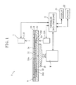
- FIGS. 1 to 5 illustrate an analyzer according to the present invention and an example of its related structure.
- the analyzer A illustrated in FIG. 1 includes an optical measurement unit 1 for measuring the absorbance of a predetermined portion of an analysis tool B , and a controller 2.
- the controller 2 is structured by using a microcomputer and an example of data processor defined by the present invention.
- the optical measurement unit 1 includes a support base 10 for supporting an analysis tool B , a light emitting portion 11A and a light receiving portion 11B.
- the support base 10 is horizontally rotatable by the driving of a motor M to cause the analysis tool B to rotate together.
- the analysis tool B can be freely mounted on and removed from the support base 10.
- the light emitting portion 11A includes a plurality of LED light sources (not shown) for emitting light of different peak wavelengths and irradiates a predetermined position of the analysis tool B , which will be described later, with light from below.
- the light receiving portion 11B has a light detection function.
- the light receiving portion 11B receives the light emitted from the light emitting portion 11A and passing upward through the predetermined position of the analysis tool B and outputs a signal of a level corresponding to the strength of the light received. The signal is transmitted to the controller 2.
- the controller 2 performs processing of the data represented by the signals transmitted from the light receiving portion 11B as well as the operation control of each part of the analyzer A .
- a display 21 and a printer 22 are connected to the controller 2.
- the display 21 is structured by using e.g. a liquid crystal panel and capable of displaying analysis results or various data related thereto on the surface.
- the printer 22 is used to print such data.
- the analysis tool B is generally in the form of a disc and includes a plurality of flow paths 34 extending radially from a center hole 30a, a plurality of reaction cells 34A in which a reagent 40 is provided, a plurality of reference cells 34B in which the reagent 40 is not provided, and a plurality of basis portions 34C, as illustrated in FIG. 2 .
- the plurality of reaction cells 34A, the plurality of reference cells 34B and the plurality of basis portions 34C are arranged on the same circumference,
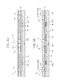
- the analysis tool B is made up of a base plate 30 generally in the form of a disc, a flow path cover 31 and a separation film 32 laminated on the upper surface of the base plate, and a protective cover 33 laminated on these parts.
- the blood BL when blood BL as a sample is applied to a center hole 33a of the protective cover 33, the blood BL passes through the separation film 32 to reach the hole 30a of the base plate 30 and is retained in the hole,
- the separation film 32 functions to separate the solid components (blood cell components) of the blood BL,
- the plurality of flow paths 34 are defined between the upper surface of the base plate 30 and the flow path cover 31. Before the analysis of the blood BL is started, the other end of each flow path 34 is kept closed, so that the blood BL retained in the hole 33a is prevented from moving toward the other end of each flow path 34.
- the operation of making a hole 31 a in the flow path cover 31 may be performed by providing a laser light source (not shown) in the optical measurement unit 1 and applying a laser beam to the flow path cover 31 through the hole 33b of the protective cover 33, for example.
- the reaction cells 34A are formed by making a portion of each flow path 34 wider than other portions.
- the reagent 40 is in the form of a solid which dissolves when blood BL is supplied thereto and contains a component which develops a color upon reaction with a particular component contained in the blood BL.
- a plurality of kinds of reagents 40 which differ from each other in components or composition are used.
- the analyzer A when a reaction portion of the blood BL and the reagent 40 is formed in the reaction cell 34A, the reaction portion is irradiated with light to obtain data D0 indicating the light absorption characteristics of the reaction portions.
- the data D0 does not purely indicate the light absorption characteristics of the reaction portion but is influenced by the light absorption characteristics of the base plate 30, the flow path cover 31 and the protective cover 33.
- the reference cells 34B differ from the reaction cells 34A in that the reagent 40 is not provided in the reference cells, as noted before, but are similar to the reaction cells 34A in other points.
- the depth and width of the reference cells 34B are approximately equal to those of the reaction cells 34A, and the blood BL is supplied also into the reference cells 34B. With the blood BL supplied to the reference cells 34B, the analyzer A irradiates this portion with light to obtain the first reference data D1 indicating the light absorption characteristics of this portion.
- the basis potions 34C are the portions at which the reaction and the reference cells 34A, 34B are not formed and which are determined to be a target portion of absorbance measurement.
- the analyzer A irradiates the basis portion 34C with light to obtain the second reference data D2 indicating the light absorption characteristics of this portion.
- the basis portion 34C and the portions formed with the reaction or the reference cells 34A, 34B have the substantially same sectional structure, Specifically, the reaction and the reference cells 34A, 34B are provided by forming a groove in the upper surface of the base plate 30 and covering the top of the groove with the flow path cover 31.
- the basis portion 34C is a portion at which the upper surface of the base plate 30 is covered with the flow path cover 31 without forming a groove.
- the thickness and material of the base plate 30 and the flow path cover 31 at the basis portion 34C are made as equal as possible to those at the portions formed with the cells 34A, 34B.
- the thickness and material of the protective cover are also made uniform.
- the base plate 30 and the protective cover 33 are made of transparent polystyrene, whereas the flow path cover 31 is made of a transparent PET film.
- the controller 2 drives the light emitting portion 11A to perform optical measurement (Step S1).
- data is obtained which indicates the light absorption characteristics of an airspace between the light emitting portion 11A and the light receiving portion 11B.
- This data is to be utilized for determining whether or not the value of the second reference data D2 obtained in a later step is proper.
- the controller 2 drives the above-described laser light source to execute the operation to make a hole 31a in the flow path cover 31 of the analysis tool B , as described in FIX.48 (Step S2:YES, Step S3).
- the blood BL which has been applied to the hole 33a of the analysis tool B , moves in the flow path 34.
- the above-described operation to make a hole is successively performed with respect to each of the plurality of flow paths 34 while successively rotating the support base 10 and the analysis tool B through a predetermined angle.
- the blood BL is successively supplied to each of the reaction cells 34A and reference cells 34B.
- Step S4 the controller 2 executes the operation to irradiate the basis portion 34C of the analysis tool B with light to obtain the second reference data D2 indicating the light absorption characteristics of this portion. Then, whether or not the value of the second reference data D2 is normal is determined (Step S5).
- This determination is made based on whether or not the value of the second reference data D2 is within a predetermined range relative to the value of the data on the light absorption characteristics of the airspace obtained in the Step S1. When the value of the second reference data is not within the predetermined range, it is determined that the value is not normal because of any trouble.
- Step S5:NO, Step S17 a notice to that effect is given, and the analysis processing is stopped.
- the notice is given by displaying a predetermined message on the display 21. This holds true for other notices which will be described later.
- the controller 2 executes the operation to irradiate the reference cell 34B with light to obtain the first reference data D1 (Step S5:YES, Step S6). Then, based on the first and the second reference data D 1 and D2, the controller 2 calculates the data D3 on the unreacted sample (Step S7).
- the data D3 on the unreacted sample is e.g. the data indicating the absorbance of the blood BL itself (i.e., the blood BL before the reaction with the reagent 40) and calculated as follows.
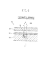
- the present embodiment as a method to obtain the data D3 on the unreacted sample, it may be considered to use the reference data D9 shown in FIG. 6 as a comparative example.
- the present embodiment is more favorable than the comparative example, because the comparative example has the following drawbacks.
- a cell 90 to which the blood BL is not to be supplied is formed in the analysis tool B1, and the reference data D9 is obtained by irradiating this portion with light.
- the light traveling to the cell 90 is scattered and reflected at the interface between the airspace in the cell 90 and the base plate 30.
- the light is scattered and reflected also at the interface between the airspace and the flow path cover 31.
- the reference data D9 does not precisely reflect the absorbance of the portion formed with the cell 90.
- the data D3 on the unreacted sample is computed based on the reference data D9 and the first reference data D 1 unlike the present embodiment, quite incorrect data is obtained.
- the basis portion 34C of the present embodiment is not formed with a cell as illustrated in FIG, 5 , such scattering and reflection of light as seen in the comparative example does not occur or hardly occur.
- the second reference data D2 precisely reflects the absorbance of the basis portion 34C itself. Because of the absence of a cell, the thickness of the base plate 30 is larger at the basis portion 34C than at the portion formed with the reference cell 34B.
- the respective absorbances differ from each other, which is not only because of the presence or absence of blood but also because of the above-described difference in thickness of the base plate 30.
- the depth of the reference cell 34B is e.g. about 100 ⁇ m, and the absorbance of the base plate 30 corresponding to a thickness of about 100 ⁇ m is small and negligible.
- the absorbance is further smaller.
- the second reference data D2 precisely indicates the optical characteristics of the basis portion 34C and is suitable as the correct data indicating the optical characteristics of the background of the reference cell 34B.
- the data D3 on the unreacted sample which corresponds to the actual absorbance of the blood BL is properly obtained.
- the first reference data D1 also precisely reflects the actual absorbance of the portion formed with the reference cell 34B, and hence, is suitable for the obtainment of precise data D3 on the unreacted sample.
- the second reference data D2 obtained by irradiating each of the plurality of basis portions 34C with light.
- the second reference data D2 may not be obtained properly when dust or the like is on the basis portion 34C, for example.
- the arrangement of this embodiment also includes a plurality of reference cells 34B, a plurality of first reference data D1 can also be obtained, which makes the data D3 on the unreacted sample more precise.
- a plurality of first and second reference data D1 and D2 can be obtained by repetitively irradiating the basis portion 34C or the reference cell 34B with light at appropriate time intervals.
- the plurality of first and second reference data D1 and D2 correspond to changes with time in each part of the analysis tool B (changes in temperature, for example), which makes the data D3 on the unreacted sample more precise.
- the controller 2 determines based on the data D3 whether or not the blood BL is a hemolysis sample. Specifically, in the data D3 on the unreacted sample, the controller 2 compares the absorbance Ab4 with respect to light having a wavelength around 410 nm and the absorbance Ab5 with respect to light having a wavelength around 445 nm.
- the controller 2 determines that the blood BL is a hemolysis sample (Step S8,Step S9:NO, Step S18). While the peak wavelength of the absorption spectrum of hemoglobin in blood BL is 410 nm, the peak wavelength of the absorption spectrum of bilirubin is 445 nm. Thus, the absorbances Ab4 and Ab5 with respect to these wavelengths should be Ab4 ⁇ Ab5.
- the blood BL is determined to be a hemolysis sample.
- the absorbances Ab4 and Ab5 two kinds of LED light sources which emit light having a peak wavelength around 410 nm and a peak wavelength around 445 nm, respectively, are provided in the light emitting portion 11A. By individually turning on the two LED light sources, the respective absorbances are obtained individually.
- the controller 2 determines whether or not the hemolysis is of a mild degree lower than a predetermined reference. When the hemolysis is mild, the controller gives a notice to that effect and then proceeds to the subsequent analysis step (Step S19:YES, Step S20). On the other hand, when the hemolysis is determined to be severe, a notice to that effect is given, and the analysis processing is stopped (Step S 19:NO, Step S21, Step S22).
- the controller 2 further determines whether or not the blood BL is a chyle sample. For instance, in the data D3 on the unreacted sample, the controller 2 compares the absorbance Ab6 with respect to light in a wavelength band of e.g. 800 nm with a predetermined threshold TH1.
- the controller determines that the sample is a chyle sample (Step S10,Step S 11:NO, Step S 15). Since chyle blood is turbid or milky white, it has a high absorbance with respect to light in a very wide band of wavelengths, particularly in a long-wavelength band. Thus, when the sample is not chyle, the relation Ab6 ⁇ TH1 holds, and when this relation does not hold, the sample is determined to be chyle.
- Step S15 the controller 2 gives a notice to that effect and then proceeds to the subsequent analysis step (Step S15, Step S 16).
- the degree of chyle may be examined and a different step may be performed depending on whether or not the degree is mild.
- the presence or absence of hemolysis and chyle in the blood BL is determined based on the data D3 on the unreacted sample.
- the data D3 on the unreacted sample is the data indicating the absorbance of the blood BL itself obtained based on the first and the second reference data D 1 and D2. This ensures correct determination of the presence or absence of hemolysis and chyle. Thus, it is possible to prevent the analysis result of the blood BL from being shown as a correct result without any notice, with the hemolysis or chyle overlooked.
- the controller 2 executes an operation to irradiate the reaction cell 34A with light to obtain the data D0 on the reaction portion (Step S12). Then, the controller 2 corrects the data D0 on the reaction portion by utilizing the first reference data D1, calculates the absorbance of the reaction portion of the blood BL and the reagent 40, and then obtains a target measurement value such as the concentration of a particular component in the blood BL (Step S13, Step S14).
- the first reference data D1 corresponds to, or serves as an alternative to the blank correction data in the conventional technique. Since the first reference data is obtained by irradiating the reference cell 34B which is not provided with the reagent 40 with light as noted before, the value is not influenced by the light transmittance of the reagent 40 and hence precise.
- the controller 2 performs correction to correct the inaccuracy of data caused by the dilution of the blood BL with the reagent 40 and the changes in color of the blood BL in accordance with the kind of the reagent.
- the data for this correction processing can be prepared in advance by conducting an examination and stored in the controller 2. This correction processing further enhances the measurement accuracy.
- the present invention is not limited to the foregoing embodiment.
- the specific arrangement of each step of the sample analysis method according to the present invention can be varied in various ways.
- the specif structure of each part of the analyzer according to the present invention can be varied in various ways.
- the sample in the present invention is not limited to blood, and urine and various other substances can also be used as a sample.
- the reagent is selected appropriately in accordance with the kind of the sample or the items to be measured.
- the specific structure of the analysis tool used for the analysis is not limitative.
- a reaction cell, a reference cell and a basis portion can be arranged on a straight line.
- these portions can be successively irradiated with light by moving the analysis tool and the optical measurement unit linearly relative to each other.
Landscapes
- Physics & Mathematics (AREA)
- Chemical & Material Sciences (AREA)
- Pathology (AREA)
- General Health & Medical Sciences (AREA)
- Immunology (AREA)
- Health & Medical Sciences (AREA)
- Life Sciences & Earth Sciences (AREA)
- Analytical Chemistry (AREA)
- Biochemistry (AREA)
- General Physics & Mathematics (AREA)
- Chemical Kinetics & Catalysis (AREA)
- Plasma & Fusion (AREA)
- Engineering & Computer Science (AREA)
- Spectroscopy & Molecular Physics (AREA)
- Investigating Or Analysing Materials By The Use Of Chemical Reactions (AREA)
- Investigating Or Analysing Biological Materials (AREA)
- Investigating Or Analysing Materials By Optical Means (AREA)
Abstract
Description
- The present invention relates to a method for analyzing a sample such as blood by using an optical technique and to an analyzer.
- In a method to analyze a sample by using an optical technique, use is made of an analysis tool including a cell in which a reagent is provided (see e.g. Patent Document 1). In this method, a sample is supplied into the cell to cause the sample to react with the reagent. The reaction portion of the sample and the reagent is irradiated with light, whereby optical data on the reaction portion such as the amount of light transmitted or reflected is obtained. The sample is analyzed based on this data.
- In this method, the sample is often diluted before it is subjected to the reaction with the reagent. Since the color of the sample becomes lighter due to the dilution, the optical data on the above-described reaction portion is not largely influenced by the color of the sample. Correction processing called blank correction is also often performed in this method.
- Specifically, in the blank correction, a cell provided with a reagent is irradiated with light in a condition in which a sample is not supplied thereto, whereby optical data (blank correction data) on this portion is obtained. By utilizing this data, the optical data on the reaction portion is corrected.
- However, the above-described conventional analysis method has the following drawbacks.
- In the conventional method, the sample itself before the reaction with the reagent is not analyzed precisely. Thus, even if the sample is not normal and the color or concentration of the sample is abnormal, the analysis of the sample is performed, with such abnormalities overlooked. Specifically, in the case where the sample is blood, the blood is yellow when it has a high bilirubin, red when it is hemolysis and milky white when it is chyle.
- In the conventional analysis method, even when the sample blood has such an abnormal color, it is not detected in advance, and the sample blood is analyzed by the reaction with a reagent. Thus, there is a possibility that although the blood itself is abnormal, the abnormality is overlooked and the analysis is regarded as right. When the blood is diluted before the reaction with the reagent, the above-described color abnormalities are more likely to be overlooked.
- The reagent can be provided in a cell of the analysis tool in various manners. For instance, the reagent may be provided in the form of a solid in the cell, so that the surface of the reagent may readily scatter and reflect light. The reagent may include a high content of substance which has a high absorbance. In these cases, when the cell is irradiated with light to obtain the above-described blank correction data, the light is scattered and reflected by the reagent or easily absorbed by the reagent.
- As a result, the amount of light which passes through the cell reduces. The blank correction data obtained based on such a small amount of light transmission tends to be incorrect, so that it is difficult to properly correct the optical data on the above-described reaction portion.
Patent Document 1:U.S. Patent No. 3 526 480 - An object of the present invention is to provide a sample analysis method and an analyzer capable of eliminating or lessening the above-described drawbacks.
- According to a first aspect of the present invention, there is provided a method for analyzing a sample by using an analysis tool including at least one reaction cell provided with a reagent. The method includes the step of irradiating a reaction portion of a sample and the reagent with light to obtain data indicating optical characteristics of the reaction portion when the reaction portion is formed due to supply of the sample to the reaction cell.
- The method further includes the following steps:
- irradiating a reference cell, which is formed in the analysis tool and which is not provided with a reagent, with light in a state in which the sample is supplied to the reference cell to obtain first reference data indicating optical characteristics of the reference cell;
- irradiating a basis portion defined in the analysis tool with light to obtain second reference data indicating optical characteristics of the basis portion, the basis portion being a portion of the analysis tool at which the reaction cell and the reference cell are not formed and which has a substantially same sectional structure as a portion formed with the reference cell except absence of a cell; and
- obtaining data on the unreacted sample indicating optical characteristics of the sample before reaction with the reagent based on the first and the second reference data.
- Preferably, the method for analyzing a sample according to the present invention further includes the step of determining whether or not the color or concentration of the sample is normal based on the data on the unreacted sample.
- Preferably, the method for analyzing a sample according to the present invention further includes the step of correcting the optical data on the reaction portion by utilizing the first reference data to obtain more precise optical data on the reaction portion.
- According to a second aspect of the present invention, there is provided an analyzer including an optical measurement means which is capable of, with an analysis tool including at least one reaction cell provided with a reagent set at a predetermined position, irradiating a reaction portion of a sample and the reagent with light to obtain data indicating optical characteristics of the reaction portion when the reaction portion is formed by supplying the sample to the reaction cell, and a data processor for processing the data.
- When the analysis tool includes a reference cell which is not provided with the reagent, the optical measurement means irradiates the reference cell with light in a state in which the sample is supplied to the reference cell to obtain first reference data indicating optical characteristics of the reference cell.
- The optical measurement means irradiates a basis portion of the analysis tool with light to obtain second reference data indicating optical characteristics of the basis portion. The basis portion is a portion at which the reaction cell and the reference cell are not formed and which has a substantially same sectional structure as a portion formed with the reference cell except absence of a cell.
- Preferably, the data processor executes processing to obtain data on the unreacted sample which indicates optical characteristics of the sample before reaction with the reagent based on the first and the second reference data.
- Preferably, the basis portions are set at a plurality of positions, and the optical measurement means irradiate the plurality of basis portions with light to obtain a plurality of second reference data. The data processor utilizes the plurality of second reference data to obtain the data on the unreacted sample.
- Preferably, the optical measurement means perform the operation to irradiate the basis portion with light a plurality of times with time intervals to obtain the plurality of second reference data. The data processor utilizes the plurality of second reference data to obtain the data on the unreacted sample.
- Preferably, the data processor determines whether or not the color or concentration of the sample is normal based on the data on the unreacted sample.
- Preferably, in the case where the sample is blood, the data processor determines that the blood is hemolysis when the absorbance with respect to light of a wavelength around 410 nm in the data on the unreacted sample is lower than that with respect to light of a wavelength around 445 nm.
- Preferably, in the case where the sample is blood, the data processor determines that the blood is chyle when the absorbance with respect to light of a predetermined wavelength in the data on the unreacted sample is higher than a predetermined threshold.
- Preferably, the data processor corrects the data indicating the optical characteristics of the reaction portion by utilizing the first reference data to obtain correction data indicating more precise optical characteristics of the reaction portion and obtaining measurement of a predetermined item of the sample based on the correction data.
- Preferably, in obtaining measurement of a predetermined item of the sample, the data processor performs correction to reduce the inaccuracy of data caused by the dilution of the sample with the reagent and the changes in color of the sample in accordance with the kind of the reagent.
- Preferably, the reaction cell, the reference cell and the basis portion of the analysis tool are arranged on the same circumference. The optical measurement means are capable of successively irradiating the reaction cell, the reference cell and the basis portion with light by rotating the analysis tool relative to the light source for irradiation.
- Other features and advantages of the present invention will become more apparent from description of embodiments of the present invention given below with reference to the accompanying drawings.
-
- FIG. 1
- is an external view illustrating an example of an analyzer according to the present invention.
- FIG. 2
- is a plan view schematically illustrating an example of main structure of an analysis tool for use in the analyzer illustrated in
FIG. 1 . - FIG. 3
- is an exploded perspective view of the analysis tool illustrated in
FIG. 2 . - FIGS. 4A and 4B
- are sectional views of the analysis tool illustrated in
FIG. 2 . - FIG. 5
- is a sectional view illustrating a principal portion of an example of a reaction cell, a reference cell and a basis portion of the analysis tool.
- FIG. 6
- is a sectional view illustrating a principal portion of a comparative example relative to the present invention.
- FIG. 7
- is a flowchart illustrating an example of data processing process by a controller of the analyzer illustrated in
FIG. 1 . - Preferred embodiments of the present invention are described below in detail with reference to the accompanying drawings.
-
FIGS. 1 to 5 illustrate an analyzer according to the present invention and an example of its related structure. The analyzer A illustrated inFIG. 1 includes anoptical measurement unit 1 for measuring the absorbance of a predetermined portion of an analysis tool B, and acontroller 2. Thecontroller 2 is structured by using a microcomputer and an example of data processor defined by the present invention. - The
optical measurement unit 1 includes asupport base 10 for supporting an analysis tool B, alight emitting portion 11A and alight receiving portion 11B. Thesupport base 10 is horizontally rotatable by the driving of a motor M to cause the analysis tool B to rotate together. The analysis tool B can be freely mounted on and removed from thesupport base 10. - The
light emitting portion 11A includes a plurality of LED light sources (not shown) for emitting light of different peak wavelengths and irradiates a predetermined position of the analysis tool B, which will be described later, with light from below. - The
light receiving portion 11B has a light detection function. Thelight receiving portion 11B receives the light emitted from thelight emitting portion 11A and passing upward through the predetermined position of the analysis tool B and outputs a signal of a level corresponding to the strength of the light received. The signal is transmitted to thecontroller 2. - The
controller 2 performs processing of the data represented by the signals transmitted from thelight receiving portion 11B as well as the operation control of each part of the analyzer A. The details will be described later. Adisplay 21 and aprinter 22 are connected to thecontroller 2. Thedisplay 21 is structured by using e.g. a liquid crystal panel and capable of displaying analysis results or various data related thereto on the surface. Theprinter 22 is used to print such data. - The analysis tool B is generally in the form of a disc and includes a plurality of
flow paths 34 extending radially from acenter hole 30a, a plurality ofreaction cells 34A in which areagent 40 is provided, a plurality ofreference cells 34B in which thereagent 40 is not provided, and a plurality ofbasis portions 34C, as illustrated inFIG. 2 . The plurality ofreaction cells 34A, the plurality ofreference cells 34B and the plurality ofbasis portions 34C are arranged on the same circumference, - As illustrated in
FIGS. 3 ,4A and 4B , the analysis tool B is made up of abase plate 30 generally in the form of a disc, a flow path cover 31 and aseparation film 32 laminated on the upper surface of the base plate, and aprotective cover 33 laminated on these parts. - As illustrated in
FIG. 4A , when blood BL as a sample is applied to acenter hole 33a of theprotective cover 33, the blood BL passes through theseparation film 32 to reach thehole 30a of thebase plate 30 and is retained in the hole, Theseparation film 32 functions to separate the solid components (blood cell components) of the blood BL, - The plurality of
flow paths 34, each of which is connected to thehole 30a at one end thereof, are defined between the upper surface of thebase plate 30 and the flow path cover 31. Before the analysis of the blood BL is started, the other end of eachflow path 34 is kept closed, so that the blood BL retained in thehole 33a is prevented from moving toward the other end of eachflow path 34. - When a
hole 3 1 a is made in the flow path cover 31 as illustrated inFIG. 4B so that the other end side of eachflow path 34 is released to the atmosphere, the blood BL which has been retained in thehole 30a moves toward the other end side of theflow path 34 by capillary action as indicated by arrows NI. The blood BL is supplied into thereaction cell 34A, which is provided at an intermediate portion of eachflow path 34, and reacts with thereagent 40. - The operation of making a
hole 31 a in the flow path cover 31 may be performed by providing a laser light source (not shown) in theoptical measurement unit 1 and applying a laser beam to the flow path cover 31 through thehole 33b of theprotective cover 33, for example. - The
reaction cells 34A are formed by making a portion of eachflow path 34 wider than other portions. Thereagent 40 is in the form of a solid which dissolves when blood BL is supplied thereto and contains a component which develops a color upon reaction with a particular component contained in the blood BL. - In this embodiment, to perform measurement with respect to a plurality of items of the blood BL, a plurality of kinds of
reagents 40 which differ from each other in components or composition are used. As illustrated inFIG. 5 , in the analyzer A, when a reaction portion of the blood BL and thereagent 40 is formed in thereaction cell 34A, the reaction portion is irradiated with light to obtain data D0 indicating the light absorption characteristics of the reaction portions. - However, the data D0 does not purely indicate the light absorption characteristics of the reaction portion but is influenced by the light absorption characteristics of the
base plate 30, the flow path cover 31 and theprotective cover 33. - The
reference cells 34B differ from thereaction cells 34A in that thereagent 40 is not provided in the reference cells, as noted before, but are similar to thereaction cells 34A in other points. - Specifically, the depth and width of the
reference cells 34B are approximately equal to those of thereaction cells 34A, and the blood BL is supplied also into thereference cells 34B. With the blood BL supplied to thereference cells 34B, the analyzer A irradiates this portion with light to obtain the first reference data D1 indicating the light absorption characteristics of this portion. - The
basis potions 34C are the portions at which the reaction and thereference cells basis portion 34C with light to obtain the second reference data D2 indicating the light absorption characteristics of this portion. - Except for the presence or absence of the cells, the
basis portion 34C and the portions formed with the reaction or thereference cells reference cells base plate 30 and covering the top of the groove with the flow path cover 31. - On the other hand, the
basis portion 34C is a portion at which the upper surface of thebase plate 30 is covered with the flow path cover 31 without forming a groove. The thickness and material of thebase plate 30 and the flow path cover 31 at thebasis portion 34C are made as equal as possible to those at the portions formed with thecells - Since the measurement light passes through the
protective cover 33 provided on the flow path cover 31, the thickness and material of the protective cover are also made uniform. For instance, thebase plate 30 and theprotective cover 33 are made of transparent polystyrene, whereas the flow path cover 31 is made of a transparent PET film. - An example of method for analyzing the blood BL using the analysis tool B and the analyzer A is described below. An example of data processing process by the
controller 2 of the analyzer A is also described with reference to the flowchart ofFIG. 7 . - First, in the state in which the analysis tool B is not set on the
support base 10, thecontroller 2 drives thelight emitting portion 11A to perform optical measurement (Step S1). In this optical measurement, data is obtained which indicates the light absorption characteristics of an airspace between thelight emitting portion 11A and thelight receiving portion 11B. - This data is to be utilized for determining whether or not the value of the second reference data D2 obtained in a later step is proper. Then, when the analysis tool B is set on the
support base 10, thecontroller 2 drives the above-described laser light source to execute the operation to make ahole 31a in the flow path cover 31 of the analysis tool B, as described in FIX.48 (Step S2:YES, Step S3). By this operation, the blood BL, which has been applied to thehole 33a of the analysis tool B, moves in theflow path 34. - The above-described operation to make a hole is successively performed with respect to each of the plurality of
flow paths 34 while successively rotating thesupport base 10 and the analysis tool B through a predetermined angle. By this operation, the blood BL is successively supplied to each of thereaction cells 34A andreference cells 34B. - Then, the
controller 2 executes the operation to irradiate thebasis portion 34C of the analysis tool B with light to obtain the second reference data D2 indicating the light absorption characteristics of this portion (Step S4). Then, whether or not the value of the second reference data D2 is normal is determined (Step S5). - This determination is made based on whether or not the value of the second reference data D2 is within a predetermined range relative to the value of the data on the light absorption characteristics of the airspace obtained in the Step S1. When the value of the second reference data is not within the predetermined range, it is determined that the value is not normal because of any trouble.
- When it is determined that the value is not normal, a notice to that effect is given, and the analysis processing is stopped (Step S5:NO, Step S17). For instance, the notice is given by displaying a predetermined message on the
display 21. This holds true for other notices which will be described later. - When the value of the second reference data D2 is normal, the
controller 2 executes the operation to irradiate thereference cell 34B with light to obtain the first reference data D1 (Step S5:YES, Step S6). Then, based on the first and the secondreference data D 1 and D2, thecontroller 2 calculates the data D3 on the unreacted sample (Step S7). The data D3 on the unreacted sample is e.g. the data indicating the absorbance of the blood BL itself (i.e., the blood BL before the reaction with the reagent 40) and calculated as follows. - First, the respective absorbances Ab1 and Ab2 of the
reference cell 34B and thebasis portion 34C are calculated based on the first reference data D1 and the second reference data D2. Then, the absorbance Ab3 of the blood BL is found by the formula: Ab3 = Ab1 - Ab2, for example. - Unlike the present embodiment, as a method to obtain the data D3 on the unreacted sample, it may be considered to use the reference data D9 shown in
FIG. 6 as a comparative example. However, the present embodiment is more favorable than the comparative example, because the comparative example has the following drawbacks. - In the comparative example shown in
FIG. 6 , acell 90 to which the blood BL is not to be supplied is formed in the analysis tool B1, and the reference data D9 is obtained by irradiating this portion with light. In this comparative example, the light traveling to thecell 90 is scattered and reflected at the interface between the airspace in thecell 90 and thebase plate 30. The light is scattered and reflected also at the interface between the airspace and the flow path cover 31. - Since a large amount of light is scattered and reflected in this way, the reference data D9 does not precisely reflect the absorbance of the portion formed with the
cell 90. Thus, when the data D3 on the unreacted sample is computed based on the reference data D9 and the firstreference data D 1 unlike the present embodiment, quite incorrect data is obtained. - By contrast, since the
basis portion 34C of the present embodiment is not formed with a cell as illustrated inFIG, 5 , such scattering and reflection of light as seen in the comparative example does not occur or hardly occur. Thus, the second reference data D2 precisely reflects the absorbance of thebasis portion 34C itself. Because of the absence of a cell, the thickness of thebase plate 30 is larger at thebasis portion 34C than at the portion formed with thereference cell 34B. - Thus, when the second reference data D2 is compared with the first reference data D1, the respective absorbances differ from each other, which is not only because of the presence or absence of blood but also because of the above-described difference in thickness of the
base plate 30. However, the depth of thereference cell 34B is e.g. about 100 µm, and the absorbance of thebase plate 30 corresponding to a thickness of about 100 µm is small and negligible. When thebase plate 30 has a high light transmittance, the absorbance is further smaller. - Thus, the second reference data D2 precisely indicates the optical characteristics of the
basis portion 34C and is suitable as the correct data indicating the optical characteristics of the background of thereference cell 34B. Thus, based on the first and the second reference data D1 and D2, the data D3 on the unreacted sample which corresponds to the actual absorbance of the blood BL is properly obtained. - As to the
reference cell 34B, light is less scattered and reflected at this cell than in the comparative example ofFIG. 6 , because the blood BL is supplied to the cell. Thus, the first reference data D1 also precisely reflects the actual absorbance of the portion formed with thereference cell 34B, and hence, is suitable for the obtainment of precise data D3 on the unreacted sample. - To obtain the data D3 on the unreacted sample, it is possible to utilize a plurality of second reference data D2 obtained by irradiating each of the plurality of
basis portions 34C with light. In the case where only asingle basis portion 34C is provided in the analysis tool B unlike the present embodiment, the second reference data D2 may not be obtained properly when dust or the like is on thebasis portion 34C, for example. - Unlike this, when a plurality of second reference data D2 are obtained by irradiating each of the plurality of
basis portions 34C with light, such a problem is eliminated and the data D3 on the unreacted sample is obtained more precisely. As a method to utilize the plurality of second reference data D2, an approximation curve using time as a parameter may be obtained based on a plurality of absorbance values obtained from the plurality of second reference data D2, and the values of the approximation curve may be used. - Since the arrangement of this embodiment also includes a plurality of
reference cells 34B, a plurality of first reference data D1 can also be obtained, which makes the data D3 on the unreacted sample more precise. - Though not illustrated in
FIG. 7 , a plurality of first and second reference data D1 and D2 can be obtained by repetitively irradiating thebasis portion 34C or thereference cell 34B with light at appropriate time intervals. With this method, the plurality of first and second reference data D1 and D2 correspond to changes with time in each part of the analysis tool B (changes in temperature, for example), which makes the data D3 on the unreacted sample more precise. - After the data D3 on the unreacted sample has been obtained, the
controller 2 determines based on the data D3 whether or not the blood BL is a hemolysis sample. Specifically, in the data D3 on the unreacted sample, thecontroller 2 compares the absorbance Ab4 with respect to light having a wavelength around 410 nm and the absorbance Ab5 with respect to light having a wavelength around 445 nm. - When the relation Ab4 < Ab5 does not hold, the
controller 2 determines that the blood BL is a hemolysis sample (Step S8,Step S9:NO, Step S18). While the peak wavelength of the absorption spectrum of hemoglobin in blood BL is 410 nm, the peak wavelength of the absorption spectrum of bilirubin is 445 nm. Thus, the absorbances Ab4 and Ab5 with respect to these wavelengths should be Ab4 < Ab5. - Thus, when this relation does not hold, the blood BL is determined to be a hemolysis sample. To easily obtain the absorbances Ab4 and Ab5, two kinds of LED light sources which emit light having a peak wavelength around 410 nm and a peak wavelength around 445 nm, respectively, are provided in the
light emitting portion 11A. By individually turning on the two LED light sources, the respective absorbances are obtained individually. - When the blood BL is determined to be a hemolysis sample, the
controller 2 determines whether or not the hemolysis is of a mild degree lower than a predetermined reference. When the hemolysis is mild, the controller gives a notice to that effect and then proceeds to the subsequent analysis step (Step S19:YES, Step S20). On the other hand, when the hemolysis is determined to be severe, a notice to that effect is given, and the analysis processing is stopped (Step S 19:NO, Step S21, Step S22). - The
controller 2 further determines whether or not the blood BL is a chyle sample. For instance, in the data D3 on the unreacted sample, thecontroller 2 compares the absorbance Ab6 with respect to light in a wavelength band of e.g. 800 nm with a predetermined threshold TH1. - When the relation Ab6 < TH1 does not hold, the controller determines that the sample is a chyle sample (Step S10,Step S 11:NO, Step S 15). Since chyle blood is turbid or milky white, it has a high absorbance with respect to light in a very wide band of wavelengths, particularly in a long-wavelength band. Thus, when the sample is not chyle, the relation Ab6 < TH1 holds, and when this relation does not hold, the sample is determined to be chyle.
- When the sample is determined to be chyle, the
controller 2 gives a notice to that effect and then proceeds to the subsequent analysis step (Step S15, Step S 16). Alternatively, in this case, similarly to the case of hemolysis, the degree of chyle may be examined and a different step may be performed depending on whether or not the degree is mild. - As described above, in this analysis method, the presence or absence of hemolysis and chyle in the blood BL is determined based on the data D3 on the unreacted sample. Herein, the data D3 on the unreacted sample is the data indicating the absorbance of the blood BL itself obtained based on the first and the second
reference data D 1 and D2. This ensures correct determination of the presence or absence of hemolysis and chyle. Thus, it is possible to prevent the analysis result of the blood BL from being shown as a correct result without any notice, with the hemolysis or chyle overlooked. - After the above-described step, the
controller 2 executes an operation to irradiate thereaction cell 34A with light to obtain the data D0 on the reaction portion (Step S12). Then, thecontroller 2 corrects the data D0 on the reaction portion by utilizing the first reference data D1, calculates the absorbance of the reaction portion of the blood BL and thereagent 40, and then obtains a target measurement value such as the concentration of a particular component in the blood BL (Step S13, Step S14). - The first reference data D1 corresponds to, or serves as an alternative to the blank correction data in the conventional technique. Since the first reference data is obtained by irradiating the
reference cell 34B which is not provided with thereagent 40 with light as noted before, the value is not influenced by the light transmittance of thereagent 40 and hence precise. - Specifically, even when the
reagent 40 has a surface which readily scatters and reflects light, such scattering and reflection of light by thereagent 40 does not occur in irradiating thereference cell 34B with light. Thus, a large amount of light passes through thereference cell 34B, so that the value of the first reference data D1 obtained is precise. - In the above-described processing, the dilution of the blood BL with the
reagent 40 is not taken into consideration. Though not illustrated inFIG. 7 , in the Step S14 for obtaining a measurement value, thecontroller 2 performs correction to correct the inaccuracy of data caused by the dilution of the blood BL with thereagent 40 and the changes in color of the blood BL in accordance with the kind of the reagent. - The data for this correction processing can be prepared in advance by conducting an examination and stored in the
controller 2. This correction processing further enhances the measurement accuracy. - The present invention is not limited to the foregoing embodiment. The specific arrangement of each step of the sample analysis method according to the present invention can be varied in various ways. Further, the specif structure of each part of the analyzer according to the present invention can be varied in various ways.
- The sample in the present invention is not limited to blood, and urine and various other substances can also be used as a sample. The reagent is selected appropriately in accordance with the kind of the sample or the items to be measured. The specific structure of the analysis tool used for the analysis is not limitative.
- For instance, a reaction cell, a reference cell and a basis portion can be arranged on a straight line. In this case, these portions can be successively irradiated with light by moving the analysis tool and the optical measurement unit linearly relative to each other.
Claims (10)
- A method for analyzing a sample by using an analysis tool including at least one reaction cell provided with a reagent, the method including the step of irradiating a reaction portion of a sample and the reagent with light to obtain data indicating optical characteristics of the reaction portion when the reaction portion is formed due to supply of the sample to the reaction cell, wherein the method further comprises the steps of:- irradiating a reference cell, which is formed in the analysis tool and which is not provided with a reagent, with light in a state in which the sample is supplied to the reference cell to obtain first reference data indicating optical characteristics of the reference cell;- irradiating a basis portion defined in the analysis tool with light to obtain second reference data indicating optical characteristics of the basis portion, the basis portion being a portion of the analysis tool at which the reaction cell and the reference cell are not formed and which has a substantially same sectional structure as a portion formed with the reference cell except absence of a cell; and- obtaining data on the unreacted sample indicating optical characteristics of the sample before reaction with the reagent based on the first and the second reference data.
- The method for analyzing a sample according to claim 1,
further comprising the step of determining whether or not color or concentration of the sample is normal based on the data on the unreacted sample. - The method for analyzing a sample according to claim 1 or 2,
further comprising the step of correcting the optical data on the reaction portion by utilizing the first reference data to obtain more precise optical data on the reaction portion. - An analyzer comprising:- optical measurement means which are capable of, with an analysis tool including at least one reaction cell provided with a reagent set at a predetermined position, irradiating a reaction portion of a sample and the reagent with light to obtain data indicating optical characteristics of the reaction portion when the reaction portion is formed by supplying the sample to the reaction cell; and a data processor for processing the data; wherein:- when the analysis tool includes a reference cell which is not provided with the reagent, the optical measurement means irradiate the reference cell with light in a state in which the sample is supplied to the reference cell to obtain first reference data indicating optical characteristics of the reference cell; and- the optical measurement means irradiate a basis portion of the analysis tool with light to obtain second reference data indicating optical characteristics of the basis portion, the basis portion being a portion at which the reaction cell and the reference cell are not formed and which has a substantially same sectional structure as a portion formed with the reference cell except absence of a cell.
- The analyzer according to claim 4,
wherein the data processor executes processing to obtain data on the unreacted sample which indicates optical characteristics of the sample before reaction with the reagent based on the first and the second reference data. - The analyzer according to claim 5,
wherein the basis portion is set at a plurality of positions;
wherein the optical measurement means irradiate the plurality of basis portions with light to obtain a plurality of second reference data; and
wherein the data processor utilizes the plurality of second reference data to obtain the data on the unreacted sample. - The analyzer according to claim 5 or 6,
wherein the optical measurement means perform the operation to irradiate the basis portion with light a plurality of times with time intervals to obtain the plurality of second reference data; and
wherein the data processor utilizes the plurality of second reference data to obtain the data on the unreacted sample. - The analyzer according to any one of claims 5 to 7,
wherein the data processor determines whether or not color or concentration of the sample is normal based on the data on the unreacted sample. - The analyzer according to any one of claims 5 to 8,
wherein, in the case where the sample is blood, the data processor determines that the blood is hemolysis when absorbance with respect to light of a wavelength around 410 nm in the data on the unreacted sample is lower than that with respect to light of a wavelength around 445 nm. - The analyzer according to any one of claims 5 to 9,
wherein, in the case where the sample is blood, the data processor determines that the blood is chyle when the absorbance with respect to light of a predetermined wavelength in the data on the unreacted sample is higher than a predetermined threshold.
Applications Claiming Priority (2)
| Application Number | Priority Date | Filing Date | Title |
|---|---|---|---|
| JP2007282001 | 2007-10-30 | ||
| PCT/JP2008/069686 WO2009057659A1 (en) | 2007-10-30 | 2008-10-29 | Method for analyzing sample and its device |
Publications (2)
| Publication Number | Publication Date |
|---|---|
| EP2211168A1 true EP2211168A1 (en) | 2010-07-28 |
| EP2211168A4 EP2211168A4 (en) | 2014-04-02 |
Family
ID=40591047
Family Applications (1)
| Application Number | Title | Priority Date | Filing Date |
|---|---|---|---|
| EP08845034.1A Withdrawn EP2211168A4 (en) | 2007-10-30 | 2008-10-29 | SAMPLE ANALYSIS METHOD AND DEVICE THEREOF |
Country Status (5)
| Country | Link |
|---|---|
| US (1) | US9176049B2 (en) |
| EP (1) | EP2211168A4 (en) |
| JP (1) | JP5442447B2 (en) |
| CN (1) | CN101821610B (en) |
| WO (1) | WO2009057659A1 (en) |
Families Citing this family (9)
| Publication number | Priority date | Publication date | Assignee | Title |
|---|---|---|---|---|
| JP6134210B2 (en) * | 2013-06-19 | 2017-05-24 | 株式会社日立ハイテクノロジーズ | Automatic analyzer and automatic analysis method |
| CN110554007A (en) | 2014-04-30 | 2019-12-10 | 仪器实验室公司 | Method and system for point-of-care coagulation assay by light detection |
| TWI562829B (en) * | 2015-06-17 | 2016-12-21 | Delta Electronics Inc | Centrifugal channel device and centrifugal channel main body |
| WO2017187490A1 (en) * | 2016-04-26 | 2017-11-02 | 株式会社日立ハイテクノロジーズ | Analytical device |
| CN106092902A (en) * | 2016-06-30 | 2016-11-09 | 上海市奉贤区中心医院 | Medical scanning devices |
| JP6786039B2 (en) * | 2017-03-03 | 2020-11-18 | 国立大学法人 熊本大学 | Optical measurement system, optical cell and optical measurement method |
| CN113777338B (en) * | 2017-12-26 | 2025-06-06 | 株式会社日立高新技术 | Automatic analysis device and automatic analysis method |
| KR102794186B1 (en) * | 2020-07-03 | 2025-04-11 | 에스케이하이닉스 주식회사 | Concentration measuring device and concentration measurement and conc`etration calibration method using same |
| JP2023140137A (en) * | 2022-03-22 | 2023-10-04 | 富士フイルム株式会社 | Analyzer and method |
Family Cites Families (13)
| Publication number | Priority date | Publication date | Assignee | Title |
|---|---|---|---|---|
| US3526480A (en) * | 1966-12-15 | 1970-09-01 | Xerox Corp | Automated chemical analyzer |
| US3953136A (en) * | 1974-03-15 | 1976-04-27 | Hach Chemical Company | Method and apparatus for automatically analyzing fluids |
| JP3203798B2 (en) | 1992-08-17 | 2001-08-27 | 株式会社島津製作所 | How to measure chromogen |
| WO2000068671A2 (en) * | 1999-05-12 | 2000-11-16 | Aclara Biosciences, Inc. | Multiplexed fluorescent detection in microfluidic devices |
| US6448089B1 (en) * | 1999-10-12 | 2002-09-10 | Aurora Biosciences Corporation | Multiwell scanner and scanning method |
| US6586257B1 (en) * | 1999-10-12 | 2003-07-01 | Vertex Pharmaceuticals Incorporated | Multiwell scanner and scanning method |
| US6814933B2 (en) * | 2000-09-19 | 2004-11-09 | Aurora Biosciences Corporation | Multiwell scanner and scanning method |
| JP4102739B2 (en) * | 2003-11-25 | 2008-06-18 | 株式会社日立ハイテクノロジーズ | Automatic analyzer |
| US7887750B2 (en) * | 2004-05-05 | 2011-02-15 | Bayer Healthcare Llc | Analytical systems, devices, and cartridges therefor |
| JP4881855B2 (en) | 2005-03-29 | 2012-02-22 | シスメックス株式会社 | Sample analysis method and sample analyzer |
| WO2007001084A1 (en) * | 2005-06-28 | 2007-01-04 | Kabushikikaisya Advance | Biochemical analyzer and carrier for biochemical analyzer |
| JP2007187445A (en) | 2006-01-11 | 2007-07-26 | Hitachi High-Technologies Corp | Automatic analyzer |
| EP1845363B1 (en) * | 2006-03-16 | 2014-08-06 | Sysmex Corporation | Sample analyzer |
-
2008
- 2008-10-29 CN CN2008801106097A patent/CN101821610B/en not_active Expired - Fee Related
- 2008-10-29 WO PCT/JP2008/069686 patent/WO2009057659A1/en not_active Ceased
- 2008-10-29 US US12/734,067 patent/US9176049B2/en active Active
- 2008-10-29 JP JP2009539095A patent/JP5442447B2/en not_active Expired - Fee Related
- 2008-10-29 EP EP08845034.1A patent/EP2211168A4/en not_active Withdrawn
Non-Patent Citations (2)
| Title |
|---|
| No further relevant documents disclosed * |
| See also references of WO2009057659A1 * |
Also Published As
| Publication number | Publication date |
|---|---|
| JP5442447B2 (en) | 2014-03-12 |
| US9176049B2 (en) | 2015-11-03 |
| CN101821610B (en) | 2012-07-18 |
| CN101821610A (en) | 2010-09-01 |
| JPWO2009057659A1 (en) | 2011-03-10 |
| US20100209964A1 (en) | 2010-08-19 |
| WO2009057659A1 (en) | 2009-05-07 |
| EP2211168A4 (en) | 2014-04-02 |
Similar Documents
| Publication | Publication Date | Title |
|---|---|---|
| US20100209964A1 (en) | Method and apparatus for analyzing sample | |
| EP2016390B1 (en) | A method and a system for quantitative hemoglobin determination | |
| EP1698883B1 (en) | Method of determining total hemoglobin concentration in undiluted and unhemolyzed whole blood | |
| US9400247B2 (en) | Automatic analyzer | |
| JP4771864B2 (en) | Biochemical analyzer | |
| US20140192342A1 (en) | Method and system for determining the concentration of substances in body fluids | |
| EP1586887B1 (en) | Spectroscopic method for total hemoglobin measurement | |
| WO2008151159A2 (en) | Through-container optical evaluation system | |
| US20250237599A1 (en) | Method and analyzer to correct for unknown interferences in a patient blood sample | |
| US20220266242A1 (en) | Rapid blood testing system | |
| WO2021166510A1 (en) | Component measurement device, component measurement device set, and information processing method | |
| EP4214498A1 (en) | Rapid blood testing system | |
| EP4325204A1 (en) | Point-of-care testing system, analyzer and method | |
| EP1870697A2 (en) | Solid control and/or calibration element for use in a diagnostic analyzer | |
| US20230349823A1 (en) | Component measurement device, component measurement device set, and information processing method | |
| WO2021166470A1 (en) | Component measurement device, component measurement device set, and information processing method | |
| WO2021166561A1 (en) | Component measurement device, component measurement device set, and information processing method |
Legal Events
| Date | Code | Title | Description |
|---|---|---|---|
| PUAI | Public reference made under article 153(3) epc to a published international application that has entered the european phase |
Free format text: ORIGINAL CODE: 0009012 |
|
| 17P | Request for examination filed |
Effective date: 20100525 |
|
| AK | Designated contracting states |
Kind code of ref document: A1 Designated state(s): AT BE BG CH CY CZ DE DK EE ES FI FR GB GR HR HU IE IS IT LI LT LU LV MC MT NL NO PL PT RO SE SI SK TR |
|
| AX | Request for extension of the european patent |
Extension state: AL BA MK RS |
|
| DAX | Request for extension of the european patent (deleted) | ||
| A4 | Supplementary search report drawn up and despatched |
Effective date: 20140303 |
|
| RIC1 | Information provided on ipc code assigned before grant |
Ipc: G01N 33/49 20060101ALI20140225BHEP Ipc: G01N 21/78 20060101AFI20140225BHEP Ipc: G01N 21/27 20060101ALI20140225BHEP Ipc: G01N 21/05 20060101ALI20140225BHEP |
|
| RAP1 | Party data changed (applicant data changed or rights of an application transferred) |
Owner name: ARKRAY, INC. |
|
| STAA | Information on the status of an ep patent application or granted ep patent |
Free format text: STATUS: EXAMINATION IS IN PROGRESS |
|
| 17Q | First examination report despatched |
Effective date: 20190318 |
|
| GRAP | Despatch of communication of intention to grant a patent |
Free format text: ORIGINAL CODE: EPIDOSNIGR1 |
|
| STAA | Information on the status of an ep patent application or granted ep patent |
Free format text: STATUS: GRANT OF PATENT IS INTENDED |
|
| INTG | Intention to grant announced |
Effective date: 20230317 |
|
| STAA | Information on the status of an ep patent application or granted ep patent |
Free format text: STATUS: THE APPLICATION IS DEEMED TO BE WITHDRAWN |
|
| 18D | Application deemed to be withdrawn |
Effective date: 20230728 |