EP2211032A2 - Heating systems to prevent freezing of condensation in breather tubes - Google Patents
Heating systems to prevent freezing of condensation in breather tubes Download PDFInfo
- Publication number
- EP2211032A2 EP2211032A2 EP10000227A EP10000227A EP2211032A2 EP 2211032 A2 EP2211032 A2 EP 2211032A2 EP 10000227 A EP10000227 A EP 10000227A EP 10000227 A EP10000227 A EP 10000227A EP 2211032 A2 EP2211032 A2 EP 2211032A2
- Authority
- EP
- European Patent Office
- Prior art keywords
- engine
- heating
- supply
- heating fluid
- fluid
- Prior art date
- Legal status (The legal status is an assumption and is not a legal conclusion. Google has not performed a legal analysis and makes no representation as to the accuracy of the status listed.)
- Withdrawn
Links
- 238000010438 heat treatment Methods 0.000 title claims abstract description 134
- 230000008014 freezing Effects 0.000 title description 6
- 238000007710 freezing Methods 0.000 title description 6
- 238000009833 condensation Methods 0.000 title description 2
- 230000005494 condensation Effects 0.000 title description 2
- 239000012530 fluid Substances 0.000 claims abstract description 113
- 239000010705 motor oil Substances 0.000 claims abstract description 21
- 239000002826 coolant Substances 0.000 claims abstract description 20
- 238000004891 communication Methods 0.000 claims abstract description 6
- 239000007789 gas Substances 0.000 claims description 56
- 239000003570 air Substances 0.000 claims description 37
- 239000003921 oil Substances 0.000 claims description 12
- 239000012080 ambient air Substances 0.000 claims description 2
- 239000007787 solid Substances 0.000 claims description 2
- 238000000034 method Methods 0.000 claims 4
- XLYOFNOQVPJJNP-UHFFFAOYSA-N water Chemical compound O XLYOFNOQVPJJNP-UHFFFAOYSA-N 0.000 description 9
- 238000002485 combustion reaction Methods 0.000 description 6
- 239000003595 mist Substances 0.000 description 3
- 229910000831 Steel Inorganic materials 0.000 description 1
- 229910052782 aluminium Inorganic materials 0.000 description 1
- XAGFODPZIPBFFR-UHFFFAOYSA-N aluminium Chemical compound [Al] XAGFODPZIPBFFR-UHFFFAOYSA-N 0.000 description 1
- 239000006227 byproduct Substances 0.000 description 1
- 239000000567 combustion gas Substances 0.000 description 1
- 239000004020 conductor Substances 0.000 description 1
- 238000010586 diagram Methods 0.000 description 1
- 238000009413 insulation Methods 0.000 description 1
- 238000004519 manufacturing process Methods 0.000 description 1
- 229910052751 metal Inorganic materials 0.000 description 1
- 239000002184 metal Substances 0.000 description 1
- 238000012986 modification Methods 0.000 description 1
- 230000004048 modification Effects 0.000 description 1
- 239000010959 steel Substances 0.000 description 1
Images

Classifications
-
- F—MECHANICAL ENGINEERING; LIGHTING; HEATING; WEAPONS; BLASTING
- F01—MACHINES OR ENGINES IN GENERAL; ENGINE PLANTS IN GENERAL; STEAM ENGINES
- F01M—LUBRICATING OF MACHINES OR ENGINES IN GENERAL; LUBRICATING INTERNAL COMBUSTION ENGINES; CRANKCASE VENTILATING
- F01M13/00—Crankcase ventilating or breathing
- F01M13/04—Crankcase ventilating or breathing having means for purifying air before leaving crankcase, e.g. removing oil
-
- F—MECHANICAL ENGINEERING; LIGHTING; HEATING; WEAPONS; BLASTING
- F01—MACHINES OR ENGINES IN GENERAL; ENGINE PLANTS IN GENERAL; STEAM ENGINES
- F01M—LUBRICATING OF MACHINES OR ENGINES IN GENERAL; LUBRICATING INTERNAL COMBUSTION ENGINES; CRANKCASE VENTILATING
- F01M13/00—Crankcase ventilating or breathing
- F01M13/04—Crankcase ventilating or breathing having means for purifying air before leaving crankcase, e.g. removing oil
- F01M2013/0455—Crankcase ventilating or breathing having means for purifying air before leaving crankcase, e.g. removing oil with a de-icing or defrosting system
-
- F—MECHANICAL ENGINEERING; LIGHTING; HEATING; WEAPONS; BLASTING
- F01—MACHINES OR ENGINES IN GENERAL; ENGINE PLANTS IN GENERAL; STEAM ENGINES
- F01M—LUBRICATING OF MACHINES OR ENGINES IN GENERAL; LUBRICATING INTERNAL COMBUSTION ENGINES; CRANKCASE VENTILATING
- F01M13/00—Crankcase ventilating or breathing
- F01M13/04—Crankcase ventilating or breathing having means for purifying air before leaving crankcase, e.g. removing oil
- F01M2013/0472—Crankcase ventilating or breathing having means for purifying air before leaving crankcase, e.g. removing oil using heating means
Definitions
- This invention pertains to internal combustion engines, particularly to the treatment of blow-by gases.
- Combustion gases are generated during the operation of an internal combustion engine. A small amount of these gases can leak past the piston seals of the internal combustion engine. These gases, commonly referred to in the art as blow-by gases, need to be released from the crankcase and are typically re-circulated into the engine air intake system or exhausted from the engine. Blow-by gases that are released from the crankcase carry combustion by-products and oil mist caused by splashing of the engine's moving components within the crankcase and the oil pan. It is known to substantially remove the oil mist from the blow-by gas prior to introduction into the intake air system. An apparatus that removes oil mist from blow-by gases is commonly referred to as a breather.
- blow by gases passing through the breather can be re-circulated into the air intake of the engine, either into the intake manifold of a normally aspirated engine or into the inlet of a turbine-driven compressor of a turbocharger arrangement.
- the blow-by gases passing through the breather are directed into the exhaust system.
- the blow-by gas can contains water vapor. Under some circumstances, this water may condense within the breather mechanism. Cold temperatures may cause freezing of this condensation within the breather mechanism.
- the outlet tube of the breather system is probably a location of increases susceptibility to freezing of water vapor.
- ice may reenter the engine air intake system. The presence of ice in various engine components could hinder the engine performance.
- Insulation has been used on outlet tubes of breather systems. Heat-producing electric resistance systems have also been used.
- the present inventor has recognized that a need exists for a mechanism that effectively and consistently prevents the freezing of water within breather systems.
- the present inventor has recognized that a need exists for a mechanism to prevent the freezing of water within breather systems that does not substantially raise the cost of the system and its production.
- the present inventor has recognized that a need exists for a mechanism to prevent the freezing of water within breather systems that does not substantially increase the complexity and size of the system.
- Exemplary embodiments of the present invention provide a heating system for use with a breather system on an engine.
- the breather system comprises an input for receiving engine gases, an arrangement for separating engine gases and engine oil and directing engine oil back into the crankcase, and an outlet conduit for directing engine gases either back into the engine air intake or to the exhaust.
- a breather system and breather is described for example in US Patent No 7,185,643 , herein incorporated by reference.
- the heating system according to the herein described embodiments includes a fluid-driven heat transfer mechanism in heat transfer communication with the breather.
- the heating system for the engine breather system includes a housing configured to contain a heating fluid to be in heat transfer communication with a portion of the engine breather system, such as with the outlet conduit.
- a heating fluid supply channel is connected to a supply of heating fluid that is at a first pressure and to the housing and arranged to direct heating fluid into the housing.
- a heating fluid return channel is connected to the housing and to a supply of heating fluid that is at a second pressure that is lower than the first pressure, and is arranged to direct heating fluid away from the housing.
- the heating system housing surrounds the portion of the breather system and the heating fluid is in heat transfer contact with the portion of the breather system.
- the supply of heating fluid includes a supply of engine oil, and an engine oil pump circulating engine oil throughout the engine by pressurizing engine oil from an engine sump.
- the pump has a discharge side for circulating the pressurized oil.
- the heating fluid supply channel is connected to the discharge side of the pump and the heating fluid return channel is connected to the sump.
- the supply of heating fluid includes a supply of engine coolant, and a coolant pump circulating coolant throughout the engine by pressurizing coolant from a lower pressure side to a higher pressure.
- the heating fluid supply channel is connected to the higher pressure side of the pump and the heating fluid return channel is connected to the lower pressure side of the pump.
- the supply of heating fluid includes a supply of engine exhaust gas in an exhaust gas system having a higher pressure side and a lower pressure side.
- the heating fluid supply channel is connected to the higher pressure side of the exhaust gas system and the heating fluid return channel is connected to the lower pressure side of the exhaust gas system.
- the supply of heating fluid includes an air compressor generating a supply of compressed air at a higher pressure from a supply of air at a lower pressure.
- the heating fluid supply channel is connected to the supply of compressed air and the heating fluid return channel is connected to the supply of air at a lower pressure, such as to ambient air.
- the housing can be in heat transfer communication with the portion of the engine breather system, such as the output conduit, by conduction through a solid member, such as a plate, and the heating fluid can be isolated from the portion of the breather system.
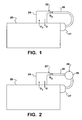
- Figure 1 is a schematic drawing of an engine and closed breather system
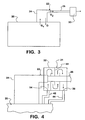
- Figure 2 is a schematic drawing of an engine and closed breather system with a turbocharger included;
- Figure 3 is a schematic drawing of an engine with an open breather system
- FIG. 4 is a schematic drawing of the heating system of the present invention.
- Figure 5 is a schematic drawing of an alternate embodiment heating system of the present invention.
- FIG. 1 is a schematic diagram that shows a vehicle engine 20 with a closed breather system 22.
- Closed breather system 22 includes a breather 24 and an outlet tube 26 as described in U.S. Patent 7,185,643 .
- Blow-by gases G 1 from engine 20 are pressured through or drawn through the engine 20 into the breather system 22.
- the gases are channeled by the breather 24 as described in US Patent 7,185,643 , oil O is removed from the gases G 1 , and gases G 2 exit the breather 24 through outlet tube 26. Oil O separated from the gases G 1 by the breather 24 flows downward into the crankcase of the engine 20.
- the outlet tube 26 directs the gases G 2 into an intake manifold 27 of the engine 20, where they will reenter the combustion process.
- FIG. 2 shows a similar arrangement but with an added turbocharger 28. Gases from the engine 20 enter the breather system 22 and exit the breather 24 through the outlet tube 26. Outlet tube 26 directs the gases G 2 to an inlet of an air compressor 29 of the turbocharger 28, and the gases G 2 along with intake air, is compressed and enters the intake manifold 27 of the engine 20 and into the combustion process.
- FIG. 3 shows the engine 20 with a breather system 22'.
- breather system 22' is an open breather system.
- Outlet tube 26 directs gases from the breather 24 into the engine exhaust system 30.
- FIG. 4 shows the heating system 31 of the present invention.
- heating system 31 is located and arranged to transfer heat into the breather system 22.
- Heating system can be arranged around outlet tube 26.
- the gases in outlet tube 26 are kept warm by heating system 31.
- Heating system 31 can be applied to a portion or the entirety of outlet tube 26.
- heating system 31 includes a housing or jacket 32 having baffles 33 as needed to cause heating fluid to flow around the tube 26 from an inlet 34 to an outlet 36.
- a heating fluid supply channel or tube 42 connects a supply of heating fluid from the engine to the inlet 34 and a heating fluid return channel or tube 44 connects the outlet 36 to a heating fluid return to the engine 20.
- the heating system 31 utilizes heating fluids that are typically already present in an engine. If the engine oil or coolant system is used, heating fluid supply tube 42 and heating fluid return tube 44 may be tubes circulating the oil or coolant from engine 20 to heating system 31.
- the oil pump that circulates engine oil throughout the engine can be used as the fluid driver to circulate engine oil through the jacket 32.
- Engine oil would be delivered from some point on the discharge side of the pump (elevated pressure) to the tube 42 and the tube 44 would be deliver engine oil from the jacket 32 to a suction side of the oil pump, such as back to the oil pan (low pressure).
- the coolant pump that circulates coolant throughout an engine and the engine radiator can be used as the fluid driver to circulate engine coolant through the jacket 32. Coolant would be delivered from some point on the discharge side of the coolant pump (elevated pressure) to the tube 42 and the tube 44 would be deliver coolant from the jacket 32 to a suction side of the coolant pump (lower pressure).
- the heating fluid supply channel 42 may be a tube connected between the exhaust gas manifold and the inlet 34 and the heating fluid return channel 44 may be a tube connected between the outlet 36 and the engine exhaust gas pipe further downstream in the exhaust gas system.
- the differential pressure between the elevated pressure of the exhaust gas from the exhaust manifold and atmospheric pressure (or the reduced pressure downstream of a turbocharger turbine) can be used to drive the exhaust gas through the jacket 32.
- heating fluid supply channel 42 may be a tube connected between the compressed air intake manifold and the inlet 34 and the heating fluid return channel 44 may be connected between the outlet 36 and atmosphere or the compressor air intake.
- the differential pressure between the elevated pressure of the compressed intake manifold air or an inter-stage air pressure and atmospheric pressure (or the intake air pressure at the compressor air intake) can be used to drive the compressed air through the jacket 32.
- FIG 5 illustrates an alternate embodiment wherein a conduction member, such as a plate 52 is solidly connected between the tube 26 and a housing 56.
- the housing 56 includes a housing inlet 60 and a housing outlet 62.
- the plate 52 and the housing 56 are composed of heat conducting material such as a metal, such as steel or aluminum.
- the inlet 60 receives heating fluid from the heating fluid supply tube 42 and the outlet 62 delivers the heating fluid to the heating fluid return tube 44.
- the housing can be configured in similar fashion as the housing 32 shown in Figure 4 or can be a pipe conducting flow in an axial direction along the axis of the pipe.
- the heating fluid can be any of those described above. Heat is transferred from the flowing heating fluid, though the housing 56, between the housing 56 and the plate 52 by conduction and between the plate 52 and the tube 26 by conduction.
Landscapes
- Engineering & Computer Science (AREA)
- Mechanical Engineering (AREA)
- General Engineering & Computer Science (AREA)
- Lubrication Details And Ventilation Of Internal Combustion Engines (AREA)
Abstract
Description
- This application claims the priority of Provisional Patent Application No.
61/147,629, filed on 27 January 2009 - This invention pertains to internal combustion engines, particularly to the treatment of blow-by gases.
- Combustion gases are generated during the operation of an internal combustion engine. A small amount of these gases can leak past the piston seals of the internal combustion engine. These gases, commonly referred to in the art as blow-by gases, need to be released from the crankcase and are typically re-circulated into the engine air intake system or exhausted from the engine. Blow-by gases that are released from the crankcase carry combustion by-products and oil mist caused by splashing of the engine's moving components within the crankcase and the oil pan. It is known to substantially remove the oil mist from the blow-by gas prior to introduction into the intake air system. An apparatus that removes oil mist from blow-by gases is commonly referred to as a breather.
- In a closed breather system, blow by gases passing through the breather can be re-circulated into the air intake of the engine, either into the intake manifold of a normally aspirated engine or into the inlet of a turbine-driven compressor of a turbocharger arrangement. Alternately, in an open breather system, the blow-by gases passing through the breather are directed into the exhaust system.
- The blow-by gas can contains water vapor. Under some circumstances, this water may condense within the breather mechanism. Cold temperatures may cause freezing of this condensation within the breather mechanism. The outlet tube of the breather system is probably a location of increases susceptibility to freezing of water vapor.
- In an open breather system, if a large amount of ice could form near the output of the breather mechanism, the flow of gas through the mechanism may be impeded. In a closed breather system, ice may reenter the engine air intake system. The presence of ice in various engine components could hinder the engine performance.
- Insulation has been used on outlet tubes of breather systems. Heat-producing electric resistance systems have also been used.
- The present inventor has recognized that a need exists for a mechanism that effectively and consistently prevents the freezing of water within breather systems.
- The present inventor has recognized that a need exists for a mechanism to prevent the freezing of water within breather systems that does not substantially raise the cost of the system and its production.
- The present inventor has recognized that a need exists for a mechanism to prevent the freezing of water within breather systems that does not substantially increase the complexity and size of the system.
- Exemplary embodiments of the present invention provide a heating system for use with a breather system on an engine. The breather system comprises an input for receiving engine gases, an arrangement for separating engine gases and engine oil and directing engine oil back into the crankcase, and an outlet conduit for directing engine gases either back into the engine air intake or to the exhaust. A breather system and breather is described for example in
US Patent No 7,185,643 , herein incorporated by reference. The heating system according to the herein described embodiments includes a fluid-driven heat transfer mechanism in heat transfer communication with the breather. - According to an exemplary embodiment, the heating system for the engine breather system includes a housing configured to contain a heating fluid to be in heat transfer communication with a portion of the engine breather system, such as with the outlet conduit. A heating fluid supply channel is connected to a supply of heating fluid that is at a first pressure and to the housing and arranged to direct heating fluid into the housing. A heating fluid return channel is connected to the housing and to a supply of heating fluid that is at a second pressure that is lower than the first pressure, and is arranged to direct heating fluid away from the housing.
- According to an exemplary embodiment, the heating system housing surrounds the portion of the breather system and the heating fluid is in heat transfer contact with the portion of the breather system.
- According to one embodiment, the supply of heating fluid includes a supply of engine oil, and an engine oil pump circulating engine oil throughout the engine by pressurizing engine oil from an engine sump. The pump has a discharge side for circulating the pressurized oil. The heating fluid supply channel is connected to the discharge side of the pump and the heating fluid return channel is connected to the sump.
- According to another embodiment, the supply of heating fluid includes a supply of engine coolant, and a coolant pump circulating coolant throughout the engine by pressurizing coolant from a lower pressure side to a higher pressure. The heating fluid supply channel is connected to the higher pressure side of the pump and the heating fluid return channel is connected to the lower pressure side of the pump.
- According to a further embodiment, the supply of heating fluid includes a supply of engine exhaust gas in an exhaust gas system having a higher pressure side and a lower pressure side. The heating fluid supply channel is connected to the higher pressure side of the exhaust gas system and the heating fluid return channel is connected to the lower pressure side of the exhaust gas system.
- According to a still further embodiment, the supply of heating fluid includes an air compressor generating a supply of compressed air at a higher pressure from a supply of air at a lower pressure. The heating fluid supply channel is connected to the supply of compressed air and the heating fluid return channel is connected to the supply of air at a lower pressure, such as to ambient air.
- According to another aspect of the aforementioned embodiments, the housing can be in heat transfer communication with the portion of the engine breather system, such as the output conduit, by conduction through a solid member, such as a plate, and the heating fluid can be isolated from the portion of the breather system.
- Numerous other advantages and features of the present invention will e become readily apparent from the following detailed description of the invention and the embodiments thereof, and from the accompanying drawings.
-
Figure 1 is a schematic drawing of an engine and closed breather system; -
Figure 2 is a schematic drawing of an engine and closed breather system with a turbocharger included; -
Figure 3 is a schematic drawing of an engine with an open breather system; -
Figure 4 is a schematic drawing of the heating system of the present invention; and -
Figure 5 is a schematic drawing of an alternate embodiment heating system of the present invention. - While this invention is susceptible of embodiment in many different forms, there are shown in the drawings, and will be described herein in detail, specific embodiments thereof with the understanding that the present disclosure is to be considered as an exemplification of the principles of the invention and is not intended to limit the invention to the specific embodiments illustrated.
-
Figure 1 is a schematic diagram that shows avehicle engine 20 with a closedbreather system 22. Closedbreather system 22 includes abreather 24 and anoutlet tube 26 as described inU.S. Patent 7,185,643 . Blow-by gases G1 fromengine 20 are pressured through or drawn through theengine 20 into thebreather system 22. The gases are channeled by thebreather 24 as described inUS Patent 7,185,643 , oil O is removed from the gases G1, and gases G2 exit thebreather 24 throughoutlet tube 26. Oil O separated from the gases G1 by thebreather 24 flows downward into the crankcase of theengine 20. In this particular embodiment, theoutlet tube 26 directs the gases G2 into anintake manifold 27 of theengine 20, where they will reenter the combustion process. -
Figure 2 shows a similar arrangement but with an addedturbocharger 28. Gases from theengine 20 enter thebreather system 22 and exit thebreather 24 through theoutlet tube 26.Outlet tube 26 directs the gases G2 to an inlet of anair compressor 29 of theturbocharger 28, and the gases G2 along with intake air, is compressed and enters theintake manifold 27 of theengine 20 and into the combustion process. -
Figure 3 shows theengine 20 with a breather system 22'. In this embodiment, breather system 22' is an open breather system.Outlet tube 26 directs gases from thebreather 24 into theengine exhaust system 30. -
Figure 4 shows theheating system 31 of the present invention. In the aforementioned embodiments,heating system 31 is located and arranged to transfer heat into thebreather system 22. Heating system can be arranged aroundoutlet tube 26. The gases inoutlet tube 26 are kept warm byheating system 31.Heating system 31 can be applied to a portion or the entirety ofoutlet tube 26. - In one embodiment,
heating system 31 includes a housing orjacket 32 havingbaffles 33 as needed to cause heating fluid to flow around thetube 26 from aninlet 34 to anoutlet 36. A heating fluid supply channel ortube 42 connects a supply of heating fluid from the engine to theinlet 34 and a heating fluid return channel ortube 44 connects theoutlet 36 to a heating fluid return to theengine 20. - The
heating system 31 utilizes heating fluids that are typically already present in an engine. If the engine oil or coolant system is used, heatingfluid supply tube 42 and heatingfluid return tube 44 may be tubes circulating the oil or coolant fromengine 20 toheating system 31. - If engine oil is used as the heating fluid, the oil pump that circulates engine oil throughout the engine can be used as the fluid driver to circulate engine oil through the
jacket 32. Engine oil would be delivered from some point on the discharge side of the pump (elevated pressure) to thetube 42 and thetube 44 would be deliver engine oil from thejacket 32 to a suction side of the oil pump, such as back to the oil pan (low pressure). - If engine coolant is used as the heating fluid, the coolant pump that circulates coolant throughout an engine and the engine radiator can be used as the fluid driver to circulate engine coolant through the
jacket 32. Coolant would be delivered from some point on the discharge side of the coolant pump (elevated pressure) to thetube 42 and thetube 44 would be deliver coolant from thejacket 32 to a suction side of the coolant pump (lower pressure). - If exhaust gas is used as the heating fluid, the heating
fluid supply channel 42 may be a tube connected between the exhaust gas manifold and theinlet 34 and the heatingfluid return channel 44 may be a tube connected between theoutlet 36 and the engine exhaust gas pipe further downstream in the exhaust gas system. The differential pressure between the elevated pressure of the exhaust gas from the exhaust manifold and atmospheric pressure (or the reduced pressure downstream of a turbocharger turbine) can be used to drive the exhaust gas through thejacket 32. - If compressed air is used as the heating fluid, heating
fluid supply channel 42 may be a tube connected between the compressed air intake manifold and theinlet 34 and the heatingfluid return channel 44 may be connected between theoutlet 36 and atmosphere or the compressor air intake. The differential pressure between the elevated pressure of the compressed intake manifold air or an inter-stage air pressure and atmospheric pressure (or the intake air pressure at the compressor air intake) can be used to drive the compressed air through thejacket 32. -
Figure 5 illustrates an alternate embodiment wherein a conduction member, such as aplate 52 is solidly connected between thetube 26 and ahousing 56. Thehousing 56 includes ahousing inlet 60 and ahousing outlet 62. Theplate 52 and thehousing 56 are composed of heat conducting material such as a metal, such as steel or aluminum. Theinlet 60 receives heating fluid from the heatingfluid supply tube 42 and theoutlet 62 delivers the heating fluid to the heatingfluid return tube 44. The housing can be configured in similar fashion as thehousing 32 shown inFigure 4 or can be a pipe conducting flow in an axial direction along the axis of the pipe. The heating fluid can be any of those described above. Heat is transferred from the flowing heating fluid, though thehousing 56, between thehousing 56 and theplate 52 by conduction and between theplate 52 and thetube 26 by conduction. - From the foregoing, it will be observed that numerous variations and modifications may be effected without departing from the spirit and scope of the invention. It is to be understood that no limitation with respect to the specific apparatus illustrated herein is intended or should be inferred.
Claims (20)
- A heating system for an engine breather system, the engine breather system having an input for receiving engine gases, an arrangement for separating engine gases and engine oil, and an outlet conduit for directing engine gases, comprising:a housing configured to contain a heating fluid to be in heat transfer communication with a portion of the engine breather system;a heating fluid supply channel connected to a supply of heating fluid that is at a first pressure and to the housing and arranged to direct heating fluid into the housing; anda heating fluid return channel connected to a supply of heating fluid that is at a second pressure that is lower than the first pressure and to the housing and arranged to direct heating fluid away from the housing.
- The heating system according to claim 1, wherein the housing surrounds the portion of the breather system and the heating fluid is in heat transfer contact with the portion of the breather system.
- The heating system according to claim 2, wherein the supply of heating fluid comprises:a supply of engine oil;an engine oil pump circulating engine oil throughout the engine by pressurizing engine oil from an engine sump, the pump having a discharge side for delivering the pressurized oil; andthe heating fluid supply channel is connected to the discharge side of the pump and the heating fluid return channel is connected to the sump.
- The heating system according to claim 2, wherein the supply of heating fluid comprises:a supply of engine coolant;a coolant pump circulating coolant throughout the engine by pressurizing coolant from a lower pressure side to a higher pressure; andthe heating fluid supply channel is connected to the higher pressure side of the pump and the heating fluid return channel is connected to the lower pressure side of the pump.
- The heating system according to claim 2, wherein the supply of heating fluid comprises:a supply of engine exhaust gas in an exhaust gas system having a higher pressure side and a lower pressure side; andthe heating fluid supply channel is connected to the higher pressure side of the exhaust gas system and the heating fluid return channel is connected to the lower pressure side of the exhaust gas system.
- The heating system according to claim 2, wherein the supply of heating fluid comprises:an air compressor generating a supply of compressed air at a higher pressure from a supply of air at a lower pressure; andthe heating fluid supply channel is connected to the supply of compressed air and the heating fluid return channel is connected to the supply of air at a lower pressure.
- The heating system according to claim 6, wherein the supply of air at a lower pressure is ambient air at atmospheric pressure.
- The heating system according to claim 1, wherein the housing is in heat transfer communication with the portion by conduction through a solid member and the heating fluid is isolated from the portion of the breather system.
- The heating system according to claim 8, wherein the supply of heating fluid comprises:a supply of engine fluid;an engine fluid pump circulating engine fluid throughout the engine by pressurizing engine fluid from a lower pressure side to a higher pressure side; andthe heating fluid supply channel is connected to the higher pressure side of the pump and the heating fluid return channel is connected to the lower pressure side of the pump.
- The heating system according to claim 8, wherein the supply of heating fluid comprises:a supply of engine exhaust gas in an exhaust gas system having a higher pressure side and a lower pressure side; andthe heating fluid supply channel is connected to the higher pressure side of the exhaust gas system and the heating fluid return channel is connected to the lower pressure side of the exhaust gas system.
- The heating system according to claim 8, wherein the supply of heating fluid comprises:an air compressor generating a supply of compressed air at a higher pressure from a supply of air at a lower pressure; andthe heating fluid supply channel is connected to the supply of compressed air and the heating fluid return channel is connected to the supply of air at a lower pressure.
- A heating system for an engine breather system, the engine breather system having an input for receiving engine gases, an arrangement for separating engine gases and engine oil, and an outlet conduit for directing engine gases, comprising:a means for heating the engine breather system;a heating fluid circulating means for directing heating fluid to the means for heating, through the means for heating, and away from the means for heating.
- The heating system according to claim 12, wherein the means for heating comprises a housing that contains heating fluid and surrounds a portion of the outlet conduit of the breather system.
- The heating system according to claim 12, wherein the heating fluid circulating means comprises:a supply of engine fluid;an engine fluid pump circulating engine fluid throughout the engine by pressurizing engine fluid from a lower pressure side to a higher pressure side; anda heating fluid supply channel connected to the higher pressure side and a heating fluid return channel connected to the lower pressure side, the heating fluid supply channel and the heating fluid return channel connected to the means for heating.
- The heating system according to claim 12, wherein the heating fluid circulating means comprises:a supply of engine exhaust gas in an exhaust gas system having a higher pressure side and a lower pressure side; anda heating fluid supply channel connected to the higher pressure side of the exhaust gas system and a heating fluid return channel connected to the lower pressure side of the exhaust gas system.
- The heating system according to claim 12, wherein the supply of heating fluid comprises:an air compressor generating a supply of compressed air at a higher pressure from a supply of air at a lower pressure; andthe heating fluid supply channel is connected to the supply of compressed air and the heating fluid return channel is connected to the supply of air at a lower pressure.
- A method of heating an engine breather system, the engine breather system having an input for receiving engine gases, an arrangement for separating engine gases and engine oil, and an outlet conduit for directing engine gases, comprising the steps of:directing a side stream of engine fluid from an engine fluid system to the engine breather system;transferring heat from the side stream to the engine breather system.
- The method according to claim 17, comprising the further step of:After the step of transferring heat, returning the side stream from the engine breather system back to the engine fluid system.
- The method according to claim 17, wherein the engine fluid is a fluid selected from the group consisting of engine oil and engine coolant.
- The method according to claim 17, wherein the engine fluid is a fluid selected from the group consisting of compressed air and engine exhaust.
Applications Claiming Priority (2)
| Application Number | Priority Date | Filing Date | Title |
|---|---|---|---|
| US14762909P | 2009-01-27 | 2009-01-27 | |
| US12/541,467 US20100186686A1 (en) | 2009-01-27 | 2009-08-14 | Heating systems to prevent freezing of condensation in breather tubes |
Publications (2)
| Publication Number | Publication Date |
|---|---|
| EP2211032A2 true EP2211032A2 (en) | 2010-07-28 |
| EP2211032A3 EP2211032A3 (en) | 2011-07-13 |
Family
ID=42116008
Family Applications (1)
| Application Number | Title | Priority Date | Filing Date |
|---|---|---|---|
| EP10000227A Withdrawn EP2211032A3 (en) | 2009-01-27 | 2010-01-12 | Heating systems to prevent freezing of condensation in breather tubes |
Country Status (2)
| Country | Link |
|---|---|
| US (1) | US20100186686A1 (en) |
| EP (1) | EP2211032A3 (en) |
Cited By (3)
| Publication number | Priority date | Publication date | Assignee | Title |
|---|---|---|---|---|
| FR2966523A1 (en) * | 2010-10-22 | 2012-04-27 | Peugeot Citroen Automobiles Sa | Air heating arrangement for internal combustion engine in motor vehicle, has conducting plate combining supercharged-air pipe and gas passage of treatment system by thermal conduction, where passage connects oil separator to intake system |
| EP2677130A1 (en) * | 2012-06-19 | 2013-12-25 | MANN+HUMMEL GmbH | Air intake system of a turbocharged internal combustion engine |
| DE102012013213A1 (en) | 2012-07-03 | 2014-01-09 | Daimler Ag | Air inlet for lifting cylinder internal combustion engine for passenger car, has heat guide element connected with housing and duct element and guiding heat to supply location by housing, where guide element is made of metallic material |
Families Citing this family (7)
| Publication number | Priority date | Publication date | Assignee | Title |
|---|---|---|---|---|
| EP2713025B1 (en) * | 2011-05-19 | 2016-09-07 | Toyota Jidosha Kabushiki Kaisha | Air intake structure for internal combustion engine |
| US9702282B2 (en) | 2014-01-14 | 2017-07-11 | Cummins Filtration Ip, Inc. | Crankcase ventilation system heater |
| DE102015009518A1 (en) | 2015-07-22 | 2017-01-26 | GM Global Technology Operations LLC (n. d. Ges. d. Staates Delaware) | Device for venting a crankshaft housing of a vehicle and drive device with such a device |
| JP6660854B2 (en) * | 2016-09-02 | 2020-03-11 | 株式会社クボタ | Oil separator exterior engine |
| JP6978881B2 (en) * | 2017-09-19 | 2021-12-08 | 北越工業株式会社 | Crankcase breather de-icing method and crankcase breather |
| JP7043328B2 (en) * | 2018-04-12 | 2022-03-29 | 株式会社クボタ | A prime mover and a working machine equipped with a prime mover |
| JP2020051352A (en) * | 2018-09-27 | 2020-04-02 | いすゞ自動車株式会社 | Blow-by gas exhaust device |
Citations (2)
| Publication number | Priority date | Publication date | Assignee | Title |
|---|---|---|---|---|
| US20060162325A1 (en) * | 2005-01-27 | 2006-07-27 | Cummins Inc. | Engine blowby injector and injection system and method for injecting blowby |
| US7185643B2 (en) | 2004-10-19 | 2007-03-06 | International Engine Intellectual Property Company, Llc | Combined filter and fill tube |
Family Cites Families (11)
| Publication number | Priority date | Publication date | Assignee | Title |
|---|---|---|---|---|
| JPS5870409U (en) * | 1981-11-07 | 1983-05-13 | 三菱重工業株式会社 | oil cooler |
| US4768493A (en) * | 1984-04-27 | 1988-09-06 | Honda Giken Kogyo Kabushiki Kaisha | Blow-by gas heating system for internal combustion engines |
| JPS61171814A (en) * | 1985-01-24 | 1986-08-02 | Fuji Heavy Ind Ltd | Blowby gas reduction device for engine |
| JPH0493710U (en) * | 1990-12-29 | 1992-08-14 | ||
| US5988134A (en) * | 1996-02-20 | 1999-11-23 | Navistar International Transportation Corp | Two piece locking oil pickup tube assembly |
| US5931131A (en) * | 1997-08-19 | 1999-08-03 | Caterpillar Inc. | Valve cover assembly having an integrated heat exchanger for cooling exhaust gases |
| US6718935B2 (en) * | 2000-01-24 | 2004-04-13 | International Engine Intellectual Property Company, Llc | Hydraulic fuel system |
| CA2378997A1 (en) * | 2001-04-23 | 2002-10-23 | Huron, Inc. | Engine intake off gas heater |
| US6412479B1 (en) * | 2001-06-20 | 2002-07-02 | Dana Corporation | Thermal management system for positive crankcase ventilation system |
| US6390080B1 (en) * | 2001-09-28 | 2002-05-21 | Ford Global Technologies, Inc. | Intake manifold with a heated PCV passage |
| US6691687B1 (en) * | 2002-12-19 | 2004-02-17 | Caterpillar Inc | Crankcase blow-by filtration system |
-
2009
- 2009-08-14 US US12/541,467 patent/US20100186686A1/en not_active Abandoned
-
2010
- 2010-01-12 EP EP10000227A patent/EP2211032A3/en not_active Withdrawn
Patent Citations (2)
| Publication number | Priority date | Publication date | Assignee | Title |
|---|---|---|---|---|
| US7185643B2 (en) | 2004-10-19 | 2007-03-06 | International Engine Intellectual Property Company, Llc | Combined filter and fill tube |
| US20060162325A1 (en) * | 2005-01-27 | 2006-07-27 | Cummins Inc. | Engine blowby injector and injection system and method for injecting blowby |
Cited By (3)
| Publication number | Priority date | Publication date | Assignee | Title |
|---|---|---|---|---|
| FR2966523A1 (en) * | 2010-10-22 | 2012-04-27 | Peugeot Citroen Automobiles Sa | Air heating arrangement for internal combustion engine in motor vehicle, has conducting plate combining supercharged-air pipe and gas passage of treatment system by thermal conduction, where passage connects oil separator to intake system |
| EP2677130A1 (en) * | 2012-06-19 | 2013-12-25 | MANN+HUMMEL GmbH | Air intake system of a turbocharged internal combustion engine |
| DE102012013213A1 (en) | 2012-07-03 | 2014-01-09 | Daimler Ag | Air inlet for lifting cylinder internal combustion engine for passenger car, has heat guide element connected with housing and duct element and guiding heat to supply location by housing, where guide element is made of metallic material |
Also Published As
| Publication number | Publication date |
|---|---|
| EP2211032A3 (en) | 2011-07-13 |
| US20100186686A1 (en) | 2010-07-29 |
Similar Documents
| Publication | Publication Date | Title |
|---|---|---|
| US20100186686A1 (en) | Heating systems to prevent freezing of condensation in breather tubes | |
| US8833073B2 (en) | Separately cooled turbocharger for maintaining a no-flow strategy of an engine block coolant jacket | |
| EP3064733A1 (en) | Engine cooling system | |
| CN102191987B (en) | Muffler draining apparatus for working machine | |
| EP2752573A1 (en) | Waste heat utilization device | |
| CN101503981B (en) | Internal combustion engine with AGR cooler | |
| EP1559883A3 (en) | Gas turbine cooling system | |
| CN101883920A (en) | Apparatus and method for return of exhaust gases in combustion engines | |
| CN1187861A (en) | Method and apparatus for cleaning IC engine crankcase blow-by gas | |
| CN109296444B (en) | Cooling system and motor vehicle | |
| CN105484826A (en) | Crankcase ventilation system | |
| CN114738076B (en) | Ventilation method of engine and crankshaft chamber | |
| US10858974B1 (en) | Lubricant coolers for marine engines | |
| CN101946065B (en) | Crank case ventilation | |
| CN101321938B (en) | A cooling system | |
| US7213394B2 (en) | Engine blowby injector and injection system and method for injecting blowby | |
| JP2014159746A (en) | Positive crankcase ventilation system | |
| EP2677130A1 (en) | Air intake system of a turbocharged internal combustion engine | |
| US8973538B2 (en) | Inline engine having side-mounted heat exchangers | |
| JP2016135996A (en) | Freezing preventive structure for blow-by gas pipe, internal combustion engine and freezing preventive method for blow-by gas pipe | |
| JP5330227B2 (en) | Engine and method for operating the engine | |
| CN107023379B (en) | Exhaust gas turbochargers for motor vehicles | |
| CN211598787U (en) | Integrated respirator and engine | |
| JP3840825B2 (en) | Outboard motor cooling structure | |
| CN109219691B (en) | Engine device |
Legal Events
| Date | Code | Title | Description |
|---|---|---|---|
| PUAI | Public reference made under article 153(3) epc to a published international application that has entered the european phase |
Free format text: ORIGINAL CODE: 0009012 |
|
| AK | Designated contracting states |
Kind code of ref document: A2 Designated state(s): AT BE BG CH CY CZ DE DK EE ES FI FR GB GR HR HU IE IS IT LI LT LU LV MC MK MT NL NO PL PT RO SE SI SK SM TR |
|
| AX | Request for extension of the european patent |
Extension state: AL BA RS |
|
| PUAL | Search report despatched |
Free format text: ORIGINAL CODE: 0009013 |
|
| AK | Designated contracting states |
Kind code of ref document: A3 Designated state(s): AT BE BG CH CY CZ DE DK EE ES FI FR GB GR HR HU IE IS IT LI LT LU LV MC MK MT NL NO PL PT RO SE SI SK SM TR |
|
| AX | Request for extension of the european patent |
Extension state: AL BA RS |
|
| 17P | Request for examination filed |
Effective date: 20120113 |
|
| 17Q | First examination report despatched |
Effective date: 20130211 |
|
| STAA | Information on the status of an ep patent application or granted ep patent |
Free format text: STATUS: THE APPLICATION IS DEEMED TO BE WITHDRAWN |
|
| 18D | Application deemed to be withdrawn |
Effective date: 20160826 |