EP2211009A2 - Outwardly opening window assembly - Google Patents
Outwardly opening window assembly Download PDFInfo
- Publication number
- EP2211009A2 EP2211009A2 EP10150148A EP10150148A EP2211009A2 EP 2211009 A2 EP2211009 A2 EP 2211009A2 EP 10150148 A EP10150148 A EP 10150148A EP 10150148 A EP10150148 A EP 10150148A EP 2211009 A2 EP2211009 A2 EP 2211009A2
- Authority
- EP
- European Patent Office
- Prior art keywords
- window
- fitting
- enforcement
- window assembly
- thermally resistive
- Prior art date
- Legal status (The legal status is an assumption and is not a legal conclusion. Google has not performed a legal analysis and makes no representation as to the accuracy of the status listed.)
- Granted
Links
Images




Classifications
-
- E—FIXED CONSTRUCTIONS
- E06—DOORS, WINDOWS, SHUTTERS, OR ROLLER BLINDS IN GENERAL; LADDERS
- E06B—FIXED OR MOVABLE CLOSURES FOR OPENINGS IN BUILDINGS, VEHICLES, FENCES OR LIKE ENCLOSURES IN GENERAL, e.g. DOORS, WINDOWS, BLINDS, GATES
- E06B3/00—Window sashes, door leaves, or like elements for closing wall or like openings; Layout of fixed or moving closures, e.g. windows in wall or like openings; Features of rigidly-mounted outer frames relating to the mounting of wing frames
- E06B3/32—Arrangements of wings characterised by the manner of movement; Arrangements of movable wings in openings; Features of wings or frames relating solely to the manner of movement of the wing
-
- E—FIXED CONSTRUCTIONS
- E06—DOORS, WINDOWS, SHUTTERS, OR ROLLER BLINDS IN GENERAL; LADDERS
- E06B—FIXED OR MOVABLE CLOSURES FOR OPENINGS IN BUILDINGS, VEHICLES, FENCES OR LIKE ENCLOSURES IN GENERAL, e.g. DOORS, WINDOWS, BLINDS, GATES
- E06B3/00—Window sashes, door leaves, or like elements for closing wall or like openings; Layout of fixed or moving closures, e.g. windows in wall or like openings; Features of rigidly-mounted outer frames relating to the mounting of wing frames
- E06B3/32—Arrangements of wings characterised by the manner of movement; Arrangements of movable wings in openings; Features of wings or frames relating solely to the manner of movement of the wing
- E06B3/325—Wings opening towards the outside
-
- E—FIXED CONSTRUCTIONS
- E06—DOORS, WINDOWS, SHUTTERS, OR ROLLER BLINDS IN GENERAL; LADDERS
- E06B—FIXED OR MOVABLE CLOSURES FOR OPENINGS IN BUILDINGS, VEHICLES, FENCES OR LIKE ENCLOSURES IN GENERAL, e.g. DOORS, WINDOWS, BLINDS, GATES
- E06B3/00—Window sashes, door leaves, or like elements for closing wall or like openings; Layout of fixed or moving closures, e.g. windows in wall or like openings; Features of rigidly-mounted outer frames relating to the mounting of wing frames
- E06B3/04—Wing frames not characterised by the manner of movement
- E06B3/263—Frames with special provision for insulation
- E06B2003/26349—Details of insulating strips
- E06B2003/2635—Specific form characteristics
- E06B2003/26361—Openings, incisions or indents
Definitions
- the present invention relates to an outwardly opening window assembly, comprising a window frame, a window sash comprising four linear profile members where at least one of said linear profile members is pivotably attached to said window frame, a window pane supported by said window sash and a locking mechanism located along at least one profile member of the sash and arranged to lock the window sash in position with respect to the window frame when said locking mechanism is engaged, each of the four linear profile members comprising:
- Thermally resistive profile members are also known for inwardly opening windows. See for example DE 94 12 123 U1 , FR 2 802 969 A1 , and DE 298 09 322 U1 .
- outwardly opening window assemblies have some important differences from inwardly opening windows which have made it impossible to use the thermally resistive profile members known from inwardly opening windows for outwardly opening window assemblies.
- the flange of the outer element and the thermally resistive element are connected by a dovetail connection.
- Figure 3 shows a schematic end view of the re-enforcement fitting and profile shown in figure 2 .
- Figure 7 shows a perspective view of a third embodiment of a re-enforcement fitting mounted on a profile as shown in figure 1 .
- Figure 11 shows a side view of the re-enforcement fitting of figure 9 .
- Figure 12 shows a top perspective view of the re-enforcement fitting of figure 9 .
- the outer element 21 comprises a horizontal flange 24 which extends under the peripheral edge 2 of the window pane 3.
- the thermally resistive element 23 connects to the flange 24 at a location which is between the plane 25 of the outside surface 4 of the window pane 3 and the plane 26 of the inside surface 5 of the window pane 3. It can be seen that the thermally resistive element 23 can be considered as a form of "extension" of the flange 24 of the outer element 21.
- locking hardware such as an espagnolette
- the locking hardware can in some cases be partially hidden from view within the inner element 22.
- the horizontal bottom portion 65 comprising a hole 66 through which the pivotable bolt may extend has a bent-up flap 68 adjacent the hole.
- the bent-up flap 68 forms a guide for the pivotable bolt 52.
Landscapes
- Engineering & Computer Science (AREA)
- Civil Engineering (AREA)
- Structural Engineering (AREA)
- Wing Frames And Configurations (AREA)
- Seal Device For Vehicle (AREA)
Abstract
Description
- The present invention relates to an outwardly opening window assembly, comprising a window frame, a window sash comprising four linear profile members where at least one of said linear profile members is pivotably attached to said window frame, a window pane supported by said window sash and a locking mechanism located along at least one profile member of the sash and arranged to lock the window sash in position with respect to the window frame when said locking mechanism is engaged, each of the four linear profile members comprising:
- an outer element which comprises:
- a surface which is in contact with a portion of the outer surface of the window pane,
- a flange which extends at least partially opposite a peripheral edge of the window pane and
- means for attaching mounting hardware to said outer element,
- a thermally resistive element which is connected to said flange of said outer element, and
- an inner element which is connected to said thermally resistive element and which comprises a surface which is in contact with a portion of the inside surface of the window pane,
- the locking mechanism being located closer to the inside of the window assembly than the innermost portion of the flange of the outer element of the profile member of the sash along which the locking mechanism is located.
- One example of a window sash having a " thermally resistive" profile member as described above is disclosed in
WO 2007/090394 A1 . - Thermally resistive profile members are also known for inwardly opening windows. See for example
DE 94 12 123 U1 ,FR 2 802 969 A1DE 298 09 322 U1 . However, outwardly opening window assemblies have some important differences from inwardly opening windows which have made it impossible to use the thermally resistive profile members known from inwardly opening windows for outwardly opening window assemblies. - One of these differences is that outwardly opening windows have the mounting hardware mounted on the outside of the window and the locking hardware mounted on the inside of the window. For example, hinges are mounted on the outer side of a profile member on the outer side of a window pane and an espagnolette, for example, is mounted on the inner side of a profile member on the inner side of the window pane. Therefore both the inner and the outer side of the profile members have to be strong.
- Inwardly opening window assemblies usually have both the mounting hardware and the locking hardware connected to the inner side of the profile member. It is therefore possible to use the thermally resistive profile members as mentioned above. These profiles are characterized in that they have a strong inner side made from aluminium and a weak outer side made from a thermally resistive material, for example plastic. Therefore, these profiles will not work for outwardly opening window assemblies since the thermally resistive element is not strong enough to support the loads placed on the inner element of an outwardly opening window assembly.
- However, in a window assembly using a profile member as disclosed in
WO 2007/090394 A1 , the material of the thermally resistive element may not be strong enough to support the locking mechanism. Therefore, according toWO 2007/090394 A1 , it is suggested to provide a window sash comprising at least one " strong" profile member that is made entirely of metal and on which the locking mechanism is mounted. The remaining profile members may be " thermally resistive" profile members comprising a thermally resistive element as described in the opening paragraph. However, it may be preferred that all four profile members are " thermally resistive" profile members. - The object of the present invention is to provide a window assembly as mentioned in the opening paragraph whereby the window assembly is strong enough to support the locking mechanism independently of the material chosen for the thermally resistive element.
- In view of this object, the window assembly further comprises at least one re-enforcement fitting which is fastened to the outer element of one of the linear profile members of the window sash and which, in a closed position of the window assembly, extends away from the plane of the window pane in a direction towards the inside of the window assembly such that at least a portion of said fitting is located between at least a portion of the inner element which is connected to said thermally resistive element and a portion of the window frame, and the re-enforcement fitting is in supporting contact with a portion of the locking mechanism.
- Thereby, although the locking mechanism may be mounted on the thermally resistive element, the re-enforcement fitting may provide the necessary support for the locking mechanism, as the re-enforcement fitting is mounted on the stronger outer element of one of the linear profile members of the window sash. The locking mechanism may also be mounted directly on the re-enforcement fitting.
- In an embodiment, the thermally resistive element is connected to the flange of the outer element at a location between the plane of the inside surface of the window pane and the plane of the outside surface of the window pane, and the thermally resistive element extends past the plane of the inside surface of the window pane. By arranging the connection plane in this manner, the distance between the cold outer element and the warm inside of the window can be increased, thereby improving the thermal properties of the window assembly.
- In a structurally advantageous embodiment, the flange of the outer element and the thermally resistive element are connected by a dovetail connection.
- In an embodiment, the extent in the vertical direction of the engagement between the flange of the outer element and the thermally resistive element is smaller than 1/2, and preferably smaller than 1/3, of the thickness of the window pane. Thereby, it is possible to obtain a very slim window assembly. The re-enforcement fitting may ensure that the necessary strength is provided to the locking mechanism.
- In a structurally advantageous embodiment, the re-enforcement fitting is fastened to a top surface of the outer element, and the outer element preferably has the form of an essentially horizontal hollow box shaped section. Thereby, the distance between the fastening point and the locking mechanism may be shorter, and the re-enforcement fitting may support the locking mechanism without having to penetrate the thermally resistive element.
- In a structurally advantageous embodiment, the inner element is a profile having a hollow section, the locking mechanism is partly arranged inside said hollow section, and the re-enforcement fitting extends into the hollow section of the profile of the inner element through a cutout in a wall of the profile of the inner element.
- In a structurally advantageous embodiment, the re-enforcement fitting is formed from a metal plate having a substantially flat mounting section abutting a top surface of the outer element and having a locking device engagement section located above the thermally resistive element, and the locking device engagement section is provided with bent-up flaps adapted for engagement with and support of a portion of the locking device.
- In an embodiment, the re-enforcement fitting has bent-down flaps engaging a channel of the thermally resistive element. The bent-down flaps may assist when positioning the re-enforcement fitting during assembly. Furthermore, the bent-down flaps may also re-enforce the connection between the outer element and the thermally resistive element.
- In an embodiment, a portion of the re-enforcement fitting extends near the peripheral edge of the window pane and is glued to the peripheral edge of the window pane. Thereby, further strength may be provided to mounting of the re-enforcement fitting from the window pane.
- In an embodiment, the window assembly comprises a first re-enforcement fitting that is in supporting contact with an espagnolette housing carrying a handle and at least a second re-enforcement fitting that is in supporting contact with a pivotable bolt, and the pivotable bolt may be pivoted by operation of the handle.
- In an embodiment, the espagnolette housing has a housing wall substantially parallel to the window pane, and the housing wall is arranged between an edge of a central flat part of the locking device engagement section of the first re-enforcement fitting and two oppositely arranged bent-up flaps of the locking device engagement section of the first re-enforcement fitting.
- In an embodiment, the espagnolette housing has two parallel housing walls formed by a bent plate, a central part of the bent portion being cut away, so that two hollow legs are formed that are inserted into two spaced holes, respectively, formed in the thermally resistive element, and the hollow legs are locked into place by means of wedges inserted into the hollow legs at the lower side of the thermally resistive element.
- In an embodiment, the locking device engagement section of the second re-enforcement fitting has two opposed bent-up flaps forming a guide for the pivotable bolt and for a longitudinally displaceable bolt forming connection between the handle and the pivotable bolt, and one of said bent-up flaps has an oblong hole forming a bearing for a tap connecting the pivotable bolt and the longitudinally displaceable bolt.
- In an embodiment, the substantially flat mounting section of the second re-enforcement fitting has the form of a narrow tongue that continues into a narrow bent-down portion of the locking device engagement section, said narrow bent-down portion comprises, in continuation, a downward inclined portion, subsequently a horizontal part supporting the lower side of the longitudinally displaceable bolt, subsequently a vertically downward directed wall portion extending sideward into a first one of the two opposed bent-up flaps forming a guide, subsequently a horizontal bottom portion comprising a hole through which the pivotable bolt may extend, and subsequently a vertically upward directed wall portion extending sideward into a second one of the two opposed bent-up flaps forming a guide.
- In an embodiment, the horizontal bottom portion comprising a hole through which the pivotable bolt may extend has a bent-up flap adjacent the hole, and said bent-up flap forms a guide for the pivotable bolt.
- In an embodiment, the means for attaching mounting hardware comprises a channel arranged on the bottom surface of the essentially horizontal hollow box shaped section of the outer element and that the thermally resistive element is connected to one of the channel walls of said essentially horizontal hollow box shaped section.
- In an embodiment, the inner element and the thermally resistive element are snap connected together.
- It should be mentioned that in the current specification, mounting hardware is defined as the hardware which is used to hold the window sash connected to the window frame. For example, the hinges are considered to be mounting hardware. Locking hardware is defined as the hardware which keeps the window closed. For example, an espagnolette is considered to be locking hardware.
- It should also be mentioned that when a term in this specification refers to an orientation, for example, upper, lower, etc. then this term is to be interpreted with respect to the orientation of the profile members as shown in the attached figures. The terms inside and outside respectively refer to the inside and the outside of the window assembly in the case that it were installed in a house. The description "centre of the window pane" refers to the centre of the entire window pane when it is seen from the outside; it does not refer to a point between the two panes of glass in a double glazed window pane.
- In this respect it should also be mentioned, that if a feature of the profile element is described or claimed, the description or claim refers to the cross section of the profile element.
- Furthermore, an object described as being "thermally resistive" in this specification is to be understood as being an object having a coefficient of thermal conduction which is lower than that of aluminium.
- The invention will now be described in greater detail with reference to the embodiments shown in the attached very schematic figures. It is to be noted that the embodiments described herein are to be used as examples only and should not limit the scope of the invention in any way.
-
Figure 1 shows a schematic cross section view of one embodiment of a profile member of an outwardly opening window assembly according to the invention. -
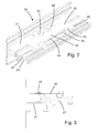
Figure 2 shows a schematic perspective view of a first embodiment of a re-enforcement fitting mounted on a profile as shown infigure 1 . -
Figure 3 shows a schematic end view of the re-enforcement fitting and profile shown infigure 2 . -
Figure 4 shows a schematic top view of the re-enforcement fitting and profile offigure 2 . -
Figure 5 shows a perspective view of the re-enforcement fitting shown infigure 2 . -
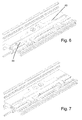
Figure 6 shows a perspective view of a second embodiment of a re-enforcement fitting mounted on a profile as shown infigure 1 . -
Figure 7 shows a perspective view of a third embodiment of a re-enforcement fitting mounted on a profile as shown infigure 1 . -
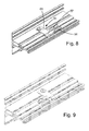
Figure 8 shows a perspective view of a fourth embodiment of a re-enforcement fitting mounted on a profile as shown infigure 1 . -
Figure 9 shows a perspective view of a fifth embodiment of a re-enforcement fitting mounted on a profile as shown infigure 1 . -
Figure 10 shows a side view of the re-enforcement fitting and profile shown infigure 8 . -
Figure 11 shows a side view of the re-enforcement fitting offigure 9 . -
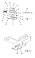
Figure 12 shows a top perspective view of the re-enforcement fitting offigure 9 . -
Figure 13 shows a bottom perspective view of the re-enforcement fitting offigure 9 . -
Figure 14 shows a bottom perspective view of first and second re-enforcement fittings supporting an espagnolette housing with a handle and a pivotable bolt, respectively. -
Figure 15 shows a side view of the espagnolette housing ofFig. 14 . -
Figure 1 shows a cross-section through alower profile member 20 of a window sash of an outwardly opening window assembly. A section of awooden window frame 17 is also shown. Theprofile member 20 is shown attached to oneperipheral edge 2 of a doubleglazed window pane 3. Thewindow pane 3 has anouter surface 4 and aninner surface 5. Theprofile member 20 comprises anouter element 21 which is in contact with theouter surface 4 of the window pane, aninner element 22 which is in contact with theinside surface 5 of the window pane, and a thermallyresistive element 23. The actual contact between the window pane and the sash elements is viaseals inner elements outer element 21 is considered to have asurface 8 which is in contact with theouter surface 4 of the window pane and theinner element 22 is considered to have asurface 9 which is in contact with theinner surface 5 of the window pane. In this way, theseals - The
outer element 21 is made of aluminium for the sake of its strength while theinner element 22 and the thermallyresistive element 23 are made from a thermally resistive material. For example theinner element 22 could be made from PVC and the thermallyresistive element 23 could be made from glass fibre re-enforced PA. However, many other types of materials could also be used. The materials can be chosen as a compromise between their strength properties and their thermal properties in order that the final window assembly has the strength and thermal properties required for the specific application. - The
outer element 21 comprises ahorizontal flange 24 which extends under theperipheral edge 2 of thewindow pane 3. The thermallyresistive element 23 connects to theflange 24 at a location which is between theplane 25 of theoutside surface 4 of thewindow pane 3 and theplane 26 of theinside surface 5 of thewindow pane 3. It can be seen that the thermallyresistive element 23 can be considered as a form of "extension" of theflange 24 of theouter element 21. - In this way, the distance "d" between the
innermost point 27 of the thermally conductive outer element and theoutermost point 28 of the inside surface of the window assembly is much larger than in prior art solutions without the thermallyresistive element 23. In such prior art solutions, thehorizontal flange 24 of theouter element 21 extends all the way to the inside of theplane 26 of theinside surface 5 of thewindow pane 3. Therefore, the thermal properties of a window assembly constructed from the profile elements as shown infigure 1 are much better than those of a window assembly constructed from profile elements without such a thermally resistive element. - The
horizontal flange 24 of theouter element 21 is formed with a hollow box shaped portion. Oneside 29 of the hollow box shaped portion is arranged at an angle to the plane of the window pane. Anattachment element 30 in the form of the female part of a dovetail joint is arranged on thisangled side 29. The thermallyresistive element 23 has a correspondinglyangled side 31 and acorresponding attachment element 32 formed as the male part of a dovetail joint. Due to the angled surface, the area of contact between the thermallyresistive element 23 and theflange 24 of theouter element 21 is increased. Due to this increased area of contact, the strength of the connection is increased. Furthermore, due to the increased length of theangled side 29, a wider dovetail joint can be used. This also increases the strength of the connection since the points of engagement of the dovetail joint are spaced further apart thereby increasing the moment which can be supported by the dovetail joint. - In order to further support the thermally resistive elements against vertical loads, the
outer element 21 comprises asupport element 36. In this case, thesupport element 36 is a horizontal flange which extends a short distance underneath the thermallyresistive element 23. There is no "positive connection" between thesupport element 36 and the thermallyresistive element 23. In this specification, positive connection is defined as a connection which works in both push and pull directions. In the current embodiment, thesupport element 36 supports the thermally resistive element via the contact between a surface of the support element and a surface of the thermally resistive element. Therefore, vertical downwardly directed loads on the thermallyresistive element 23 will be supported by thesupport element 36. However, the absence of a positive connection between the twoelements elements - Please note that a virtual "connection plane" 33 could be drawn between the thermally
resistive element 23 and theouter element 21. Note, the actual connection does not occur along a single plane, as is obvious from the figure. However, an imaginary "connection plane" 33 can be imagined as shown infigure 1 . It can be seen that this "connection plane" 33 is angled with respect to the window pane such that theside 34 of the thermally resistive element which is closest to the centre of thewindow pane 3 extends closer to the outside of the window than theside 35 of the thermally resistive element which is farthest from the centre of the window. In this way, the shortest distance between the warm inside and the coldouter element 21 is increased in comparison to a thermally resistive element having a vertical plane of connection. If the plane of connection were angled the opposite way, then the distance between the warm inside and the coldouter element 21 would be reduced. - Note that in the case of the profile element shown in
figure 1 , there is a single positive point of connection between the thermallyresistive element 23 and theouter element 21. By "positive" point of connection, is meant a point of connection which prevents relative motion between the two connected elements in both pull and push directions. This is in contrast to a simple support type of connection, as is the case between theflange 36 and the thermallyresistive element 23. However, it could also be imagined that instead of a single positive point of connection, there could be two positive connection points. In this case, the two connection points would be offset from each other and placed such that the "connection plane" would also be angled as in the current embodiment. - The
outer element 21 comprises achannel 37 for attaching mounting means (not shown). Thechannel 37 is arranged on the bottom surface of the box shaped hollow portion of theflange 24. One of thesides 38 of thechannel 37 is arranged to be a continuation of theangled side 29 of thehollow flange 24 of theouter element 21. In this way, the strength of theouter element 21 is further optimized. - In the case of the current embodiment, the inner element and the thermally resistive element are two distinct elements which are assembled during assembly of the window sash, however, in another embodiment, it could be imagined that the two elements were integrated into a single element.
- According to the invention, locking hardware, such as an espagnolette, is attached to the thermally
resistive element 23 which is located on the inner side of theplane 26. The locking hardware can in some cases be partially hidden from view within theinner element 22. - In order to support the locking hardware, a
re-enforcement fitting 40 is fastened to theouter element 21 of one of thelinear profile members 20 of the window sash.Fig. 2 shows a first re-enforcement fitting 40 mounted on aprofile member 20 as shown inFig. 1 . This re-enforcement fitting 40 is adapted to support anespagnolette housing 41 carrying a not shown handle, see alsoFigs. 14 and 15 . There-enforcement fitting 40 extends away from the plane of thewindow pane 3 in a direction towards the inside of the window assembly such that a portion of there-enforcement fitting 40 is located between a portion of theinner element 22 which is connected to the thermallyresistive element 23 and a portion of thewindow frame 17. The re-enforcement fitting is made of a material that has greater strength than the thermallyresistive element 23. The re-enforcement fitting may be of metal, such as steel or possibly aluminium. However, it may also be made from a suitable strong composite material or the like. - The
re-enforcement fitting 40 is formed from a metal plate having a substantiallyflat mounting section 43 abutting a top surface of theouter element 21 to which it is fastened by means of apop rivet 42. Furthermore, the re-enforcement fitting 40 has a lockingdevice engagement section 44 located above the thermallyresistive element 23. The lockingdevice engagement section 44 is provided with bent-upflaps 45 adapted for engagement with and support of a portion of the locking device. Furthermore, the re-enforcement fitting 40 has bent-downflaps 46 engaging achannel 47 of the thermallyresistive element 23. - The
espagnolette housing 41 illustrated inFig. 15 has ahousing wall 48 substantially parallel to thewindow pane 3, and thehousing wall 48 is arranged between anedge 49 of a central flat part of the lockingdevice engagement section 44 of the first re-enforcement fitting and the two oppositely arranged bent-upflaps 45 of the locking device engagement section. - The
espagnolette housing 41 has twoparallel housing walls 48 formed by a bent plate, a central part of the bent portion being cut away, so that twohollow legs 53 are formed that are inserted into two spacedholes 54, respectively, formed in the thermallyresistive element 23, seeFig. 2 . Thehollow legs 53 are locked into place by means of not shown wedges inserted into the hollow legs at the lower side of the thermally resistive element. -
Figs. 6 and 7 show another embodiment of the re-enforcement fitting 40 shown inFig. 2 . A portion of the re-enforcement fitting extends near the peripheral edge of the window pane and is glued to the peripheral edge of the window pane by means of a strip ofglue 50. - The window assembly comprises the above-mentioned first re-enforcement fitting 40 that is in supporting contact with the
espagnolette housing 41 and two secondre-enforcement fittings 51 that are in supporting contact with apivotable bolt 52 that may be pivoted by operation of the not shown handle.Fig. 14 shows the first re-enforcement fitting 40 and one of the two secondre-enforcement fittings 51. - A locking
device engagement section 55 of the second re-enforcement fitting 51 has two opposed bent-upflaps pivotable bolt 52 and for a longitudinallydisplaceable bolt 58 forming connection between the handle and the pivotable bolt, seeFigs. 8 ,11 and14 . One 57 of said bent-up flaps has anoblong hole 59 forming a bearing for a not shown tap connecting thepivotable bolt 52 and the longitudinallydisplaceable bolt 58. - A substantially
flat mounting section 61 of the second re-enforcement fitting 51 has the form of a narrow tongue that continues into a narrow bent-downportion 60 of the lockingdevice engagement section 55. The narrow bent-downportion 60 comprises, in continuation, a downwardinclined portion 62, subsequently ahorizontal part 63 supporting the lower side of the longitudinallydisplaceable bolt 58, subsequently a vertically downward directedwall portion 64 extending sideward into afirst one 56 of the two opposed bent-up flaps forming a guide, subsequently ahorizontal bottom portion 65 comprising ahole 66 through which thepivotable bolt 52 may extend, and subsequently a vertically upward directedwall 67 portion extending sideward into asecond one 57 of the two opposed bent-up flaps forming a guide. - The
horizontal bottom portion 65 comprising ahole 66 through which the pivotable bolt may extend has a bent-upflap 68 adjacent the hole. The bent-upflap 68 forms a guide for thepivotable bolt 52. - It is to be noted that the locking mechanism comprising the
espagnolette housing 41 and the pivotable bolts is arranged inside the hollow section of theinner element 22, and the re-enforcement fittings extend into the hollow section of the profile of the inner element through a not shown cutout in a wall of the profile of the inner element. - It should be noted that the embodiments described in this specification disclose a number of features. It will be obvious to the person skilled in the art that many of these features can be used independently of each other.
Claims (10)
- An outwardly opening window assembly, comprising a window frame, a window sash comprising four linear profile members where at least one of said linear profile members is pivotably attached to said window frame, a window pane supported by said window sash and a locking mechanism located along at least one profile member of the sash and arranged to lock the window sash in position with respect to the window frame when said locking mechanism is engaged, each of the four linear profile members comprising:an outer element which comprises:a surface which is in contact with a portion of the outer surface of the window pane,a flange which extends at least partially opposite a peripheral edge of the window pane andmeans for attaching mounting hardware to said outer element,a thermally resistive element which is connected to said flange of said outer element, andan inner element which is connected to said thermally resistive element and which comprises a surface which is in contact with a portion of the inside surface of the window pane,the locking mechanism being located closer to the inside of the window assembly than the innermost portion of the flange of the outer element of the profile member of the sash along which the locking mechanism is located, characterized in that the window assembly further comprises at least one re-enforcement fitting which is fastened to the outer element of one of the linear profile members of the window sash and which, in a closed position of the window assembly, extends away from the plane of the window pane in a direction towards the inside of the window assembly such that at least a portion of said fitting is located between at least a portion of the inner element which is connected to said thermally resistive element and a portion of the window frame, and in that the re-enforcement fitting is in supporting contact with a portion of the locking mechanism.
- A window assembly according to claim 1, characterized in that the thermally resistive element is connected to the flange of the outer element at a location between the plane of the inside surface of the window pane and the plane of the outside surface of the window pane, and in that the thermally resistive element extends past the plane of the inside surface of the window pane.
- A window assembly according to claim 1 or 2, characterized in that the extent in the vertical direction of the engagement between the flange of the outer element and the thermally resistive element is smaller than 1/2, and preferably smaller than 1/3, of the thickness of the window pane.
- A window assembly according to any one of the preceding claims, characterized in that the re-enforcement fitting is fastened to a top surface of the outer element, and in that the outer element preferably has the form of an essentially horizontal hollow box shaped section.
- A window assembly according to any one of the preceding claims, characterized in that the inner element is a profile having a hollow section, in that the locking mechanism is partly arranged inside said hollow section, and in that the re-enforcement fitting extends into the hollow section of the profile of the inner element through a cutout in a wall of the profile of the inner element.
- A window assembly according to any one of the preceding claims, characterized in that the re-enforcement fitting is formed from a metal plate having a substantially flat mounting section abutting a top surface of the outer element and having a locking device engagement section located above the thermally resistive element, and in that the locking device engagement section is provided with bent-up flaps adapted for engagement with and support of a portion of the locking device.
- A window assembly according to any one of the preceding claims, characterized in that the re-enforcement fitting has bent-down flaps engaging a channel of the thermally resistive element.
- A window assembly according to any one of the preceding claims, characterized in that a portion of the re-enforcement fitting extends near the peripheral edge of the window pane and is glued to the peripheral edge of the window pane.
- A window assembly according to any one of the preceding claims, characterized in that the window assembly comprises a first re-enforcement fitting that is in supporting contact with an espagnolette housing carrying a handle and at least a second re-enforcement fitting that is in supporting contact with a pivotable bolt, and in that the pivotable bolt may be pivoted by operation of the handle.
- A window assembly according to claim 9, characterized in that the espagnolette housing has a housing wall substantially parallel to the window pane, and in that the housing wall is arranged between an edge of a central flat part of the locking device engagement section of the first re-enforcement fitting and two oppositely arranged bent-up flaps of the locking device engagement section of the first re-enforcement fitting.
Priority Applications (1)
| Application Number | Priority Date | Filing Date | Title |
|---|---|---|---|
| PL10150148T PL2211009T3 (en) | 2009-01-23 | 2010-01-05 | Outwardly opening window assembly |
Applications Claiming Priority (1)
| Application Number | Priority Date | Filing Date | Title |
|---|---|---|---|
| DKPA200900102 | 2009-01-23 |
Publications (3)
| Publication Number | Publication Date |
|---|---|
| EP2211009A2 true EP2211009A2 (en) | 2010-07-28 |
| EP2211009A3 EP2211009A3 (en) | 2016-07-20 |
| EP2211009B1 EP2211009B1 (en) | 2017-10-04 |
Family
ID=41864948
Family Applications (1)
| Application Number | Title | Priority Date | Filing Date |
|---|---|---|---|
| EP10150148.4A Active EP2211009B1 (en) | 2009-01-23 | 2010-01-05 | Outwardly opening window assembly |
Country Status (3)
| Country | Link |
|---|---|
| EP (1) | EP2211009B1 (en) |
| DK (1) | DK2211009T3 (en) |
| PL (1) | PL2211009T3 (en) |
Cited By (1)
| Publication number | Priority date | Publication date | Assignee | Title |
|---|---|---|---|---|
| CN114396213A (en) * | 2022-01-24 | 2022-04-26 | 烟台市飞龙建筑幕墙门窗有限公司 | Low-energy-consumption aluminum alloy outward-opening window |
Citations (4)
| Publication number | Priority date | Publication date | Assignee | Title |
|---|---|---|---|---|
| DE9412123U1 (en) | 1994-07-27 | 1994-09-29 | Ekonal Bausysteme GmbH & Co. KG, 42553 Velbert | Completion for wall openings, such as windows, doors or the like. |
| DE29809322U1 (en) | 1998-05-23 | 1998-08-13 | Götz GmbH, 71636 Ludwigsburg | Window or door construction with a frame that is fixed to the building and a pivoting casement |
| FR2802969A1 (en) | 1999-12-23 | 2001-06-29 | Ouest Alu | Window or French window with opener frame of aluminum and plastic extrusions |
| WO2007090394A1 (en) | 2006-02-08 | 2007-08-16 | Vkr Holding A/S | Thermally resistive window sash member and window assembly |
-
2010
- 2010-01-05 DK DK10150148.4T patent/DK2211009T3/en active
- 2010-01-05 PL PL10150148T patent/PL2211009T3/en unknown
- 2010-01-05 EP EP10150148.4A patent/EP2211009B1/en active Active
Patent Citations (4)
| Publication number | Priority date | Publication date | Assignee | Title |
|---|---|---|---|---|
| DE9412123U1 (en) | 1994-07-27 | 1994-09-29 | Ekonal Bausysteme GmbH & Co. KG, 42553 Velbert | Completion for wall openings, such as windows, doors or the like. |
| DE29809322U1 (en) | 1998-05-23 | 1998-08-13 | Götz GmbH, 71636 Ludwigsburg | Window or door construction with a frame that is fixed to the building and a pivoting casement |
| FR2802969A1 (en) | 1999-12-23 | 2001-06-29 | Ouest Alu | Window or French window with opener frame of aluminum and plastic extrusions |
| WO2007090394A1 (en) | 2006-02-08 | 2007-08-16 | Vkr Holding A/S | Thermally resistive window sash member and window assembly |
Cited By (1)
| Publication number | Priority date | Publication date | Assignee | Title |
|---|---|---|---|---|
| CN114396213A (en) * | 2022-01-24 | 2022-04-26 | 烟台市飞龙建筑幕墙门窗有限公司 | Low-energy-consumption aluminum alloy outward-opening window |
Also Published As
| Publication number | Publication date |
|---|---|
| DK2211009T3 (en) | 2018-01-08 |
| EP2211009B1 (en) | 2017-10-04 |
| EP2211009A3 (en) | 2016-07-20 |
| PL2211009T3 (en) | 2018-03-30 |
Similar Documents
| Publication | Publication Date | Title |
|---|---|---|
| US10457182B2 (en) | Integrated door frame and handle bracket | |
| EP3333334B1 (en) | A roof window comprising a cover member | |
| EP2857622B1 (en) | Door jamb for flush in-swing door | |
| US20100077664A1 (en) | Garage door and door panel therefor | |
| NO176114B (en) | Fittings for connecting panels | |
| US9534389B2 (en) | Window system for mounting in an inclined surface of a building providing improved load transfer | |
| EP2211009B1 (en) | Outwardly opening window assembly | |
| US8082697B2 (en) | Sunscreen and mounting bracket assembly | |
| KR101404706B1 (en) | Filling piece in windows and doors | |
| EP1989385B1 (en) | Thermally resistive window sash member and window assembly | |
| KR102483861B1 (en) | Door frame strcture of sliding window | |
| KR102536394B1 (en) | Reinforcement member for slide window and Window having the same | |
| EP2674561B1 (en) | Thermally resistive window sash member and window assembly | |
| EP1635009A2 (en) | Hinged wall access panel | |
| JP3137602B2 (en) | Window sash | |
| EP3299536B1 (en) | A roof window including a set of hinges with improved movement pattern | |
| JP2007146652A (en) | Fitting | |
| AU2020257058A1 (en) | Configurable astragal and snap feature for fenestration systems | |
| JP7705532B1 (en) | Door and window frame structure | |
| EP2933419B1 (en) | Fenestration products | |
| CN111119669A (en) | window system | |
| JP7650631B2 (en) | Fittings | |
| AU6800498A (en) | A hinged panel assembly | |
| EP1640547A1 (en) | A method of attaching a cover element to a window casement, and a cover element to be attached to a window casement | |
| AU2010101456A4 (en) | A thermally broken frame |
Legal Events
| Date | Code | Title | Description |
|---|---|---|---|
| PUAI | Public reference made under article 153(3) epc to a published international application that has entered the european phase |
Free format text: ORIGINAL CODE: 0009012 |
|
| AK | Designated contracting states |
Kind code of ref document: A2 Designated state(s): AT BE BG CH CY CZ DE DK EE ES FI FR GB GR HR HU IE IS IT LI LT LU LV MC MK MT NL NO PL PT RO SE SI SK SM TR |
|
| AX | Request for extension of the european patent |
Extension state: AL BA RS |
|
| PUAL | Search report despatched |
Free format text: ORIGINAL CODE: 0009013 |
|
| AK | Designated contracting states |
Kind code of ref document: A3 Designated state(s): AT BE BG CH CY CZ DE DK EE ES FI FR GB GR HR HU IE IS IT LI LT LU LV MC MK MT NL NO PL PT RO SE SI SK SM TR |
|
| AX | Request for extension of the european patent |
Extension state: AL BA RS |
|
| RIC1 | Information provided on ipc code assigned before grant |
Ipc: E06B 3/263 20060101ALI20160614BHEP Ipc: E06B 3/32 20060101AFI20160614BHEP |
|
| 17P | Request for examination filed |
Effective date: 20170117 |
|
| RBV | Designated contracting states (corrected) |
Designated state(s): AT BE BG CH CY CZ DE DK EE ES FI FR GB GR HR HU IE IS IT LI LT LU LV MC MK MT NL NO PL PT RO SE SI SK SM TR |
|
| RIC1 | Information provided on ipc code assigned before grant |
Ipc: E06B 3/263 20060101ALI20170217BHEP Ipc: E06B 3/32 20060101AFI20170217BHEP |
|
| GRAP | Despatch of communication of intention to grant a patent |
Free format text: ORIGINAL CODE: EPIDOSNIGR1 |
|
| INTG | Intention to grant announced |
Effective date: 20170420 |
|
| GRAS | Grant fee paid |
Free format text: ORIGINAL CODE: EPIDOSNIGR3 |
|
| GRAA | (expected) grant |
Free format text: ORIGINAL CODE: 0009210 |
|
| AK | Designated contracting states |
Kind code of ref document: B1 Designated state(s): AT BE BG CH CY CZ DE DK EE ES FI FR GB GR HR HU IE IS IT LI LT LU LV MC MK MT NL NO PL PT RO SE SI SK SM TR |
|
| REG | Reference to a national code |
Ref country code: GB Ref legal event code: FG4D |
|
| REG | Reference to a national code |
Ref country code: CH Ref legal event code: EP |
|
| REG | Reference to a national code |
Ref country code: AT Ref legal event code: REF Ref document number: 934224 Country of ref document: AT Kind code of ref document: T Effective date: 20171015 |
|
| REG | Reference to a national code |
Ref country code: IE Ref legal event code: FG4D |
|
| REG | Reference to a national code |
Ref country code: DE Ref legal event code: R096 Ref document number: 602010045678 Country of ref document: DE |
|
| REG | Reference to a national code |
Ref country code: SE Ref legal event code: TRGR |
|
| REG | Reference to a national code |
Ref country code: DK Ref legal event code: T3 Effective date: 20180103 |
|
| REG | Reference to a national code |
Ref country code: NL Ref legal event code: MP Effective date: 20171004 |
|
| REG | Reference to a national code |
Ref country code: LT Ref legal event code: MG4D |
|
| REG | Reference to a national code |
Ref country code: AT Ref legal event code: MK05 Ref document number: 934224 Country of ref document: AT Kind code of ref document: T Effective date: 20171004 |
|
| PG25 | Lapsed in a contracting state [announced via postgrant information from national office to epo] |
Ref country code: NL Free format text: LAPSE BECAUSE OF FAILURE TO SUBMIT A TRANSLATION OF THE DESCRIPTION OR TO PAY THE FEE WITHIN THE PRESCRIBED TIME-LIMIT Effective date: 20171004 |
|
| PG25 | Lapsed in a contracting state [announced via postgrant information from national office to epo] |
Ref country code: LT Free format text: LAPSE BECAUSE OF FAILURE TO SUBMIT A TRANSLATION OF THE DESCRIPTION OR TO PAY THE FEE WITHIN THE PRESCRIBED TIME-LIMIT Effective date: 20171004 Ref country code: ES Free format text: LAPSE BECAUSE OF FAILURE TO SUBMIT A TRANSLATION OF THE DESCRIPTION OR TO PAY THE FEE WITHIN THE PRESCRIBED TIME-LIMIT Effective date: 20171004 Ref country code: NO Free format text: LAPSE BECAUSE OF FAILURE TO SUBMIT A TRANSLATION OF THE DESCRIPTION OR TO PAY THE FEE WITHIN THE PRESCRIBED TIME-LIMIT Effective date: 20180104 Ref country code: FI Free format text: LAPSE BECAUSE OF FAILURE TO SUBMIT A TRANSLATION OF THE DESCRIPTION OR TO PAY THE FEE WITHIN THE PRESCRIBED TIME-LIMIT Effective date: 20171004 |
|
| PG25 | Lapsed in a contracting state [announced via postgrant information from national office to epo] |
Ref country code: AT Free format text: LAPSE BECAUSE OF FAILURE TO SUBMIT A TRANSLATION OF THE DESCRIPTION OR TO PAY THE FEE WITHIN THE PRESCRIBED TIME-LIMIT Effective date: 20171004 Ref country code: HR Free format text: LAPSE BECAUSE OF FAILURE TO SUBMIT A TRANSLATION OF THE DESCRIPTION OR TO PAY THE FEE WITHIN THE PRESCRIBED TIME-LIMIT Effective date: 20171004 Ref country code: LV Free format text: LAPSE BECAUSE OF FAILURE TO SUBMIT A TRANSLATION OF THE DESCRIPTION OR TO PAY THE FEE WITHIN THE PRESCRIBED TIME-LIMIT Effective date: 20171004 Ref country code: GR Free format text: LAPSE BECAUSE OF FAILURE TO SUBMIT A TRANSLATION OF THE DESCRIPTION OR TO PAY THE FEE WITHIN THE PRESCRIBED TIME-LIMIT Effective date: 20180105 Ref country code: BG Free format text: LAPSE BECAUSE OF FAILURE TO SUBMIT A TRANSLATION OF THE DESCRIPTION OR TO PAY THE FEE WITHIN THE PRESCRIBED TIME-LIMIT Effective date: 20180104 Ref country code: IS Free format text: LAPSE BECAUSE OF FAILURE TO SUBMIT A TRANSLATION OF THE DESCRIPTION OR TO PAY THE FEE WITHIN THE PRESCRIBED TIME-LIMIT Effective date: 20180204 |
|
| REG | Reference to a national code |
Ref country code: DE Ref legal event code: R097 Ref document number: 602010045678 Country of ref document: DE |
|
| PG25 | Lapsed in a contracting state [announced via postgrant information from national office to epo] |
Ref country code: CZ Free format text: LAPSE BECAUSE OF FAILURE TO SUBMIT A TRANSLATION OF THE DESCRIPTION OR TO PAY THE FEE WITHIN THE PRESCRIBED TIME-LIMIT Effective date: 20171004 Ref country code: SK Free format text: LAPSE BECAUSE OF FAILURE TO SUBMIT A TRANSLATION OF THE DESCRIPTION OR TO PAY THE FEE WITHIN THE PRESCRIBED TIME-LIMIT Effective date: 20171004 Ref country code: EE Free format text: LAPSE BECAUSE OF FAILURE TO SUBMIT A TRANSLATION OF THE DESCRIPTION OR TO PAY THE FEE WITHIN THE PRESCRIBED TIME-LIMIT Effective date: 20171004 |
|
| PLBE | No opposition filed within time limit |
Free format text: ORIGINAL CODE: 0009261 |
|
| STAA | Information on the status of an ep patent application or granted ep patent |
Free format text: STATUS: NO OPPOSITION FILED WITHIN TIME LIMIT |
|
| PG25 | Lapsed in a contracting state [announced via postgrant information from national office to epo] |
Ref country code: RO Free format text: LAPSE BECAUSE OF FAILURE TO SUBMIT A TRANSLATION OF THE DESCRIPTION OR TO PAY THE FEE WITHIN THE PRESCRIBED TIME-LIMIT Effective date: 20171004 Ref country code: SM Free format text: LAPSE BECAUSE OF FAILURE TO SUBMIT A TRANSLATION OF THE DESCRIPTION OR TO PAY THE FEE WITHIN THE PRESCRIBED TIME-LIMIT Effective date: 20171004 Ref country code: IT Free format text: LAPSE BECAUSE OF FAILURE TO SUBMIT A TRANSLATION OF THE DESCRIPTION OR TO PAY THE FEE WITHIN THE PRESCRIBED TIME-LIMIT Effective date: 20171004 |
|
| REG | Reference to a national code |
Ref country code: CH Ref legal event code: PL |
|
| 26N | No opposition filed |
Effective date: 20180705 |
|
| PG25 | Lapsed in a contracting state [announced via postgrant information from national office to epo] |
Ref country code: LU Free format text: LAPSE BECAUSE OF NON-PAYMENT OF DUE FEES Effective date: 20180105 Ref country code: FR Free format text: LAPSE BECAUSE OF NON-PAYMENT OF DUE FEES Effective date: 20180131 |
|
| REG | Reference to a national code |
Ref country code: FR Ref legal event code: ST Effective date: 20180928 |
|
| REG | Reference to a national code |
Ref country code: BE Ref legal event code: MM Effective date: 20180131 |
|
| PG25 | Lapsed in a contracting state [announced via postgrant information from national office to epo] |
Ref country code: CH Free format text: LAPSE BECAUSE OF NON-PAYMENT OF DUE FEES Effective date: 20180131 Ref country code: BE Free format text: LAPSE BECAUSE OF NON-PAYMENT OF DUE FEES Effective date: 20180131 Ref country code: LI Free format text: LAPSE BECAUSE OF NON-PAYMENT OF DUE FEES Effective date: 20180131 Ref country code: SI Free format text: LAPSE BECAUSE OF FAILURE TO SUBMIT A TRANSLATION OF THE DESCRIPTION OR TO PAY THE FEE WITHIN THE PRESCRIBED TIME-LIMIT Effective date: 20171004 |
|
| PGFP | Annual fee paid to national office [announced via postgrant information from national office to epo] |
Ref country code: PL Payment date: 20181213 Year of fee payment: 10 |
|
| PGFP | Annual fee paid to national office [announced via postgrant information from national office to epo] |
Ref country code: SE Payment date: 20190110 Year of fee payment: 10 |
|
| PG25 | Lapsed in a contracting state [announced via postgrant information from national office to epo] |
Ref country code: MC Free format text: LAPSE BECAUSE OF FAILURE TO SUBMIT A TRANSLATION OF THE DESCRIPTION OR TO PAY THE FEE WITHIN THE PRESCRIBED TIME-LIMIT Effective date: 20171004 |
|
| PG25 | Lapsed in a contracting state [announced via postgrant information from national office to epo] |
Ref country code: MT Free format text: LAPSE BECAUSE OF NON-PAYMENT OF DUE FEES Effective date: 20180105 |
|
| PG25 | Lapsed in a contracting state [announced via postgrant information from national office to epo] |
Ref country code: TR Free format text: LAPSE BECAUSE OF FAILURE TO SUBMIT A TRANSLATION OF THE DESCRIPTION OR TO PAY THE FEE WITHIN THE PRESCRIBED TIME-LIMIT Effective date: 20171004 |
|
| PG25 | Lapsed in a contracting state [announced via postgrant information from national office to epo] |
Ref country code: HU Free format text: LAPSE BECAUSE OF FAILURE TO SUBMIT A TRANSLATION OF THE DESCRIPTION OR TO PAY THE FEE WITHIN THE PRESCRIBED TIME-LIMIT; INVALID AB INITIO Effective date: 20100105 Ref country code: PT Free format text: LAPSE BECAUSE OF FAILURE TO SUBMIT A TRANSLATION OF THE DESCRIPTION OR TO PAY THE FEE WITHIN THE PRESCRIBED TIME-LIMIT Effective date: 20171004 |
|
| PG25 | Lapsed in a contracting state [announced via postgrant information from national office to epo] |
Ref country code: CY Free format text: LAPSE BECAUSE OF FAILURE TO SUBMIT A TRANSLATION OF THE DESCRIPTION OR TO PAY THE FEE WITHIN THE PRESCRIBED TIME-LIMIT Effective date: 20171004 Ref country code: MK Free format text: LAPSE BECAUSE OF NON-PAYMENT OF DUE FEES Effective date: 20171004 |
|
| REG | Reference to a national code |
Ref country code: SE Ref legal event code: EUG |
|
| REG | Reference to a national code |
Ref country code: SE Ref legal event code: EUG |
|
| PG25 | Lapsed in a contracting state [announced via postgrant information from national office to epo] |
Ref country code: SE Free format text: LAPSE BECAUSE OF NON-PAYMENT OF DUE FEES Effective date: 20200106 |
|
| PGFP | Annual fee paid to national office [announced via postgrant information from national office to epo] |
Ref country code: IE Payment date: 20210111 Year of fee payment: 12 |
|
| PGFP | Annual fee paid to national office [announced via postgrant information from national office to epo] |
Ref country code: DE Payment date: 20201222 Year of fee payment: 12 |
|
| PG25 | Lapsed in a contracting state [announced via postgrant information from national office to epo] |
Ref country code: PL Free format text: LAPSE BECAUSE OF NON-PAYMENT OF DUE FEES Effective date: 20200105 |
|
| REG | Reference to a national code |
Ref country code: DE Ref legal event code: R119 Ref document number: 602010045678 Country of ref document: DE |
|
| PG25 | Lapsed in a contracting state [announced via postgrant information from national office to epo] |
Ref country code: DE Free format text: LAPSE BECAUSE OF NON-PAYMENT OF DUE FEES Effective date: 20220802 |
|
| PG25 | Lapsed in a contracting state [announced via postgrant information from national office to epo] |
Ref country code: IE Free format text: LAPSE BECAUSE OF NON-PAYMENT OF DUE FEES Effective date: 20220105 |
|
| PGFP | Annual fee paid to national office [announced via postgrant information from national office to epo] |
Ref country code: GB Payment date: 20231207 Year of fee payment: 15 |
|
| GBPC | Gb: european patent ceased through non-payment of renewal fee |
Effective date: 20250105 |
|
| PG25 | Lapsed in a contracting state [announced via postgrant information from national office to epo] |
Ref country code: GB Free format text: LAPSE BECAUSE OF NON-PAYMENT OF DUE FEES Effective date: 20250105 |
|
| PGFP | Annual fee paid to national office [announced via postgrant information from national office to epo] |
Ref country code: DK Payment date: 20260113 Year of fee payment: 17 |