EP2210812A2 - Ducted fan UAV control system - Google Patents
Ducted fan UAV control system Download PDFInfo
- Publication number
- EP2210812A2 EP2210812A2 EP09176566A EP09176566A EP2210812A2 EP 2210812 A2 EP2210812 A2 EP 2210812A2 EP 09176566 A EP09176566 A EP 09176566A EP 09176566 A EP09176566 A EP 09176566A EP 2210812 A2 EP2210812 A2 EP 2210812A2
- Authority
- EP
- European Patent Office
- Prior art keywords
- vehicle
- control
- ducted fan
- air
- vanes
- Prior art date
- Legal status (The legal status is an assumption and is not a legal conclusion. Google has not performed a legal analysis and makes no representation as to the accuracy of the status listed.)
- Withdrawn
Links
- RZVHIXYEVGDQDX-UHFFFAOYSA-N 9,10-anthraquinone Chemical compound C1=CC=C2C(=O)C3=CC=CC=C3C(=O)C2=C1 RZVHIXYEVGDQDX-UHFFFAOYSA-N 0.000 claims description 6
- 238000000034 method Methods 0.000 abstract description 8
- 238000013461 design Methods 0.000 description 5
- 230000005484 gravity Effects 0.000 description 4
- 238000004891 communication Methods 0.000 description 3
- 239000000446 fuel Substances 0.000 description 3
- 230000002349 favourable effect Effects 0.000 description 2
- 230000010006 flight Effects 0.000 description 2
- 230000003993 interaction Effects 0.000 description 2
- 241000408659 Darpa Species 0.000 description 1
- 230000009286 beneficial effect Effects 0.000 description 1
- 230000000903 blocking effect Effects 0.000 description 1
- 238000012986 modification Methods 0.000 description 1
- 230000004048 modification Effects 0.000 description 1
- 238000012545 processing Methods 0.000 description 1
- 238000011160 research Methods 0.000 description 1
- 230000002459 sustained effect Effects 0.000 description 1
- 230000000007 visual effect Effects 0.000 description 1
Images

Classifications
-
- B—PERFORMING OPERATIONS; TRANSPORTING
- B64—AIRCRAFT; AVIATION; COSMONAUTICS
- B64U—UNMANNED AERIAL VEHICLES [UAV]; EQUIPMENT THEREFOR
- B64U30/00—Means for producing lift; Empennages; Arrangements thereof
- B64U30/20—Rotors; Rotor supports
- B64U30/24—Coaxial rotors
-
- B—PERFORMING OPERATIONS; TRANSPORTING
- B64—AIRCRAFT; AVIATION; COSMONAUTICS
- B64C—AEROPLANES; HELICOPTERS
- B64C39/00—Aircraft not otherwise provided for
- B64C39/02—Aircraft not otherwise provided for characterised by special use
- B64C39/024—Aircraft not otherwise provided for characterised by special use of the remote controlled vehicle type, i.e. RPV
-
- B—PERFORMING OPERATIONS; TRANSPORTING
- B64—AIRCRAFT; AVIATION; COSMONAUTICS
- B64U—UNMANNED AERIAL VEHICLES [UAV]; EQUIPMENT THEREFOR
- B64U30/00—Means for producing lift; Empennages; Arrangements thereof
- B64U30/20—Rotors; Rotor supports
- B64U30/29—Constructional aspects of rotors or rotor supports; Arrangements thereof
- B64U30/296—Rotors with variable spatial positions relative to the UAV body
- B64U30/297—Tilting rotors
Definitions
- the present invention relates generally to ducted fan air-vehicles, and more particularly, relates to flight control alternatives for ducted fan air-vehicles.
- Ducted fan air-vehicles such as an Unmanned Aerial Vehicle (UAV) may have at least one ducted fan and a fan engine to drive the fan blades.
- Ducted fan air-vehicles are well-known for performance capability in multiple flight conditions. For instance, ducted fan air-vehicles have the ability of forward flight and are well known for stationary hovering aerodynamic performance.
- UAVs are remotely piloted or self-piloted aircraft that can carry cameras, sensors, communications equipment, or other payloads.
- a UAV is capable of controlled, sustained, level flight and is powered by either a jet or an engine.
- the UAVs may be remotely controlled or may fly autonomously based on preprogrammed flight plans or more complex dynamic automation systems.
- UAVs have become increasingly used for various applications where the use of manned flight vehicles is not appropriate or is not feasible.
- Such applications may include military situations, such as surveillance, reconnaissance, target acquisition, data acquisition, communications relay, decoy, harassment, or supply flights.
- military situations such as surveillance, reconnaissance, target acquisition, data acquisition, communications relay, decoy, harassment, or supply flights.
- These vehicles are also used in a growing number of civilian applications, such as firefighting when a human observer would be at risk, police observation of civil disturbances or crime scenes, reconnaissance support in natural disasters, and scientific research, such as collecting data from within a hurricane.
- UAVs are the delivery system for a payload and are developed to fill a particular application and a set of requirements. As previously mentioned, there are numerous applications for which a UAV may be used. For each new application, a different type of payload may be used. Because different payloads may require different processing capabilities, or may comprise different sizes, a variation of the UAV typically must be developed for each type of payload, or a completely new aircraft typically must be designed. Designing a new aircraft or developing a variation of the current UAV in use is time-consuming and costly.
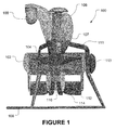
- Fig. 1 is a pictorial representation of a typical ducted fan air-vehicle 100.
- the ducted fan air-vehicle 100 includes an air duct 102 having a fan 104 located within the air duct 102.
- the ducted fan air-vehicle may have a center body 106.
- the center body 106 may be a housing that contains other components of the air-vehicle 100, such as an engine 107 for powering the air-vehicle 100, a camera, or additional components for air-vehicle operation, such as an avionics system 109.
- the ducted fan air-vehicle 100 may also include a duct pod 113.
- the ducted fan air-vehicle 100 may also include a stator assembly 110 and a plurality of fixed and/or movable vanes 112 for providing thrust vectoring for the air-vehicle 100.
- the stator assembly 110 and vanes 112 may be located downstream or under the fan 104 located within the air duct 102.
- the stator assembly 110 may be located just under the fan 104 in the air duct 102 to reduce or eliminate the swirl and torque produced by the fan 104.
- the vanes 112 may also be placed under the fan 104. For instance, the vanes 112 may be placed slightly below an exit section of the air duct 102.
- the vanes may also include moveable flap surfaces 114.
- the ducted fan-air vehicle 100 may further include engine mounts 111 which support the center body 106.
- Engine mounts 111 also provide a connection for the landing gear 108 of the UAV.
- ducted fan air-vehicles such as air-vehicle 100 preferably have clean and attached air flow around the duct lip in the multiple flight conditions. Further, ducted fan air-vehicles preferably have a favorable center of gravity in order to be effective and controllable. A uniform inflow velocity profile into the fan is also desirable to minimize the acoustic signature of the duct-fan interaction.
- ducted fan air-vehicles may need to carry a variety of components when in operation.
- ducted fan air-vehicles may need to carry, without limitation, visual sensors, infrared sensors, cameras, radio communication devices, inertial sensor units, ground level sensor units, and/or payload. Due to the limited size of the ducted fan air-vehicle, in order to store the variety of units in the ducted fan, the units may be placed in external pods that are attached to the ducted fan air-vehicle.
- These pods may (i) cause a shift in the center of gravity, (ii) create negative interference with airflow characteristics inside the duct by blocking air intake and exhaust, and (iii) create additional drag on the UAV when the UAV is in forward flight. Additionally, the added weight of the equipment may require additional engine capacity and fuel storage capacity. It may be beneficial to increase the volume within the duct lip in order to decrease or eliminate the need for external pods while maintaining the aerodynamic requirements of a ducted fan air-vehicle.
- the present disclosure describes a ducted fan air-vehicle having an air duct, a fan, a center body, and a plurality of control vanes located within the air duct.
- Each control vane has a leading edge and has a separate servo for independently controlling each vane.
- a method for controlling a ducted fan air-vehicle includes providing an air duct, a fan, and a center body, providing a plurality of control vanes located within or downstream of the air duct, each control vane having a leading edge, and providing a separate servo for each control vane.
- the method further includes deflecting the leading edges of two adjacent control vanes toward each other to generate a drag force on the air duct.
- Ducted fan air-vehicles are known for their superior stationary aerodynamic hovering performance, three-dimensional precision position hold, low speed flights, precision vertical take-off and landing (“VTOL”) and safe close-range operations.
- Ducted fan air-vehicles may be preprogrammed to perform operations autonomously, or they may be controlled by a human operator. Therefore, ducted fan air-vehicles may be unmanned aerial vehicles (“UAV").
- UAV unmanned aerial vehicles
- UAVs may have avionics equipment on board to control the flight and operation of the UAV. For instance, the avionics may control the direction, flight, stability compensation, and other aspects of flight control. Additionally, UAVs may carry a variety of equipment on board tailored to the mission the UAVs are assigned to accomplish. UAVs may carry sensors on board to obtain information about surroundings, or the UAVs may carry a payload to be deposited at a target site. The UAV engine to drive the UAV requires that fuel be carried on board the UAV. The avionics equipment, sensors, payload, and fuel may be stored on the UAV.
- ducted fan air-vehicles In order to be effective and controllable in multiple flight conditions, ducted fan air-vehicles preferably have clean and attached air flow around the duct lip in the multiple flight conditions. Further, ducted fan air-vehicles preferably have a favorable center of gravity in order to be effective and controllable. A uniform inflow velocity profile into the fan is also desirable to minimize the acoustic signature of the duct-fan interaction.
- Flight control of ducted fan-based UAVs depends on large amounts of control authority, especially when maneuvering in unsteady or turbulent winds.
- the design of the present application makes it possible to obtain additional control authority in one direction, or about one rotational axis of a ducted fan vehicle that uses otherwise conventional control vanes at the rear of the duct.
- pairs of control vanes work together, or in tandem.
- the present application uses de-coupled adjacent vanes.
- Each vane requires its own servo, or some other similar mechanism, to move independent of its neighboring vane surface.
- the servos provide mechanical torque to move and hold the control vanes in a certain position.
- the vanes move independently of each other.
- the leading edges of the control vanes may then be deflected toward each other, which generates a large drag force over that portion of the duct.
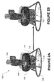
- the ducted fan air-vehicle 100 includes an air duct 102 having a fan 104 located within or downstream from the air duct 102.
- the ducted fan air-vehicle may also include a center body 106.
- the center body 106 may be a housing that contains other components of the air-vehicle 100, such as an engine 107 for powering the air-vehicle 100, a camera, or additional components for air-vehicle operation, such as an avionics system 109.
- the ducted fan-air vehicle 100 is stabilized when it is on the ground by landing gear 108. Although the landing gear 108 shown in the Figures is ring shaped, alternate types of landing gear may be used.
- the ducted fan air-vehicle 100 may also include a stator assembly 110.
- the stator assembly 110 may be located just under the fan 104 in the air duct 102 to reduce or eliminate the swirl and torque produced by the fan 104 by providing the correct amount of anti-torque to counteract engine torque.
- the stator assembly 110 may also add to the vehicle's structural integrity.
- the ducted fan air-vehicle 100 may also include a plurality of fixed or moveable control vanes 112 for providing the necessary forces and moments for vehicle control.
- the vanes 112 may be located under the fan 104 within the air duct 102.
- the vanes 112 may be connected to the air duct 102 by control vane supports 117.
- the vanes 112 may be placed slightly below an exit section of the air duct 102.
- the vanes 112 are placed in the fan airflow and away from the vehicle center of gravity (CG) location. The farther away the vanes 112 are placed from the CG, the better they are at providing moments for vehicle attitude control.
- the vanes may also include moveable flap surfaces 114 at a trailing edge 115.
- the flap surfaces 114 deflect as the control vanes 112 are deflected.
- the moveable flap surfaces 114 produce more lift than a single rigid surface.
- leading edges 116 of control vanes 112 are deflected toward each other, a large amount of drag can be generated.
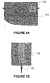
- each control vane 112 (8 surfaces total) requires its own servo or method of independent actuation.
- a servo converts electrical signals to mechanical power.
- the servo 118 may be mounted on, or internal to, the vanes 112 themselves, as shown in Fig. 3A , or may move the vanes via a system of linkages if externally mounted as shown in Fig. 3B . With each vane having its own servo 118, the vanes 112 are free to move independently.
- the vanes 112 may also generate large amounts of drag if the leading edges 116 of a vane pair are moved toward each other in a "closed" position, as shown in Figs. 2B , 4B , and 5D .
- Vehicle thrust may also be controlled to some degree by deflecting all four vane pairs 112 in a similar manner, simultaneously, to generate changes in overall vehicle thrust without changing the main fan speed or blade pitch angle. Since each vane has its own servo, the vanes can be used to produce pitch, roll, or yaw control moments to control the vehicle when operating in tandem (as shown in Figs 5A and 5B ). Pitch, roll, and yaw moments are specific moments about the vehicle x, y, and z axis directions. This method of deflecting the vanes generates drag without any resulting forces in other directions, much like a drag brake on aircraft. Drag brakes have many different forms, but may be surfaces deployed to generate aerodynamic drag to help slow down an aircraft. In a similar manner, opposed vanes can generate aerodynamic drag to tailor thrust of the fan. Possible uses of this technique include small trim changes to thrust while in flight, or large thrust changes while on the ground as part of a rapid takeoff maneuver.
- a ducted fan vehicle (as pictured in Fig 1 ) is able to quickly tilt into the wind to stabilize its flight in unsteady conditions.
- the vehicle To achieve the required nose-down tilt into the wind, the vehicle must overcome the inherent nose-up pitch moment present on the windward side of the duct lip. Therefore, tilting a ducted fan aircraft into the wind requires overcoming its natural tendency to pitch away from the oncoming wind.
- the present application gives the vehicle 100 more control authority to tilt in the direction that it needs to move in for station keeping and other mission tasks.
- a flight control system which may be part of the avionics system 109, controls the deflection of the vanes 112 by sending command signals to the servos.
- the flight control system is a collection of on-board electronics (sensors, computer, etc.), and is located wherever there is suitable space, such as in the center body 106. Some or all of the on-board electronics may also be located in the duct pod 113.
- each vane having its own servo and being able to move independently is that the vehicle's thrust can be easily tailored.
- the same concept is used, but applied to all four control vane pairs.
- the control vanes 112 provide a level of thrust control of the aircraft, independent of controlling the main lift fan's speed or blade pitch angle. This method may be useful for fine control of thrust levels for precision maneuvering or in cases when the fan speed or blade pitch angle may not respond quickly enough in turbulent wind conditions. Another situation may occur at takeoff when it is desired to provide maximum thrust as quickly as possible for rapid takeoff. With the four vane pairs in a "closed" position, the vehicle thrust is limited even though the fan may be running at full design speed. Rapid takeoff is then enabled by moving vanes quickly to zero deflection to provide full fan thrust.
- the present application is counterintuitive because independent control vanes weigh more than pairs of vanes because there are more servos. While it is true that additional servos are required for this type of control system design (one per vane surface), at least two advantages over the prior art are gained by having servos for each vane. The first is that smaller servos can be used to help offset the required increase in weight, power, and space requirements. The second is system redundancy; if one servo fails, the vehicle has a better chance of retaining control compared to the conventional design, as there is not a complete loss of functionality of one vane pair.
Abstract
A ducted fan air-vehicle (100) having alternative methods of control is described. The ducted fan air-vehicle (100) includes an air duct (102), a fan (104), a center body (106), a plurality of control vanes (112). Each control vanes (112) includes a separate servo (118) for independent control of each control vane (112), and is therefore able to operate the control vanes (112) in a non-traditional manner to provide maximum control authority.
Description
- The United States Government has acquired certain rights in this invention pursuant to Contract No. MDA072-01-0-0018, awarded by the DARPA.
- The present invention relates generally to ducted fan air-vehicles, and more particularly, relates to flight control alternatives for ducted fan air-vehicles.
- Ducted fan air-vehicles, such as an Unmanned Aerial Vehicle (UAV), may have at least one ducted fan and a fan engine to drive the fan blades. Ducted fan air-vehicles are well-known for performance capability in multiple flight conditions. For instance, ducted fan air-vehicles have the ability of forward flight and are well known for stationary hovering aerodynamic performance.
- UAVs are remotely piloted or self-piloted aircraft that can carry cameras, sensors, communications equipment, or other payloads. A UAV is capable of controlled, sustained, level flight and is powered by either a jet or an engine. The UAVs may be remotely controlled or may fly autonomously based on preprogrammed flight plans or more complex dynamic automation systems.
- UAVs have become increasingly used for various applications where the use of manned flight vehicles is not appropriate or is not feasible. Such applications may include military situations, such as surveillance, reconnaissance, target acquisition, data acquisition, communications relay, decoy, harassment, or supply flights. These vehicles are also used in a growing number of civilian applications, such as firefighting when a human observer would be at risk, police observation of civil disturbances or crime scenes, reconnaissance support in natural disasters, and scientific research, such as collecting data from within a hurricane.
- Currently, a wide variety of UAV shapes, sizes, and configurations exist. Typically it is the payload of the aircraft that is the desired product, not the aircraft itself. A payload is what the aircraft is carrying. UAVs are the delivery system for a payload and are developed to fill a particular application and a set of requirements. As previously mentioned, there are numerous applications for which a UAV may be used. For each new application, a different type of payload may be used. Because different payloads may require different processing capabilities, or may comprise different sizes, a variation of the UAV typically must be developed for each type of payload, or a completely new aircraft typically must be designed. Designing a new aircraft or developing a variation of the current UAV in use is time-consuming and costly.
-
Fig. 1 is a pictorial representation of a typical ducted fan air-vehicle 100. The ducted fan air-vehicle 100 includes anair duct 102 having afan 104 located within theair duct 102. The ducted fan air-vehicle may have acenter body 106. Thecenter body 106 may be a housing that contains other components of the air-vehicle 100, such as anengine 107 for powering the air-vehicle 100, a camera, or additional components for air-vehicle operation, such as anavionics system 109. The ducted fan air-vehicle 100 may also include a duct pod 113. - The ducted fan air-
vehicle 100 may also include astator assembly 110 and a plurality of fixed and/ormovable vanes 112 for providing thrust vectoring for the air-vehicle 100. Thestator assembly 110 andvanes 112 may be located downstream or under thefan 104 located within theair duct 102. Thestator assembly 110 may be located just under thefan 104 in theair duct 102 to reduce or eliminate the swirl and torque produced by thefan 104. Thevanes 112 may also be placed under thefan 104. For instance, thevanes 112 may be placed slightly below an exit section of theair duct 102. The vanes may also includemoveable flap surfaces 114. - The ducted fan-
air vehicle 100 may further includeengine mounts 111 which support thecenter body 106.Engine mounts 111 also provide a connection for thelanding gear 108 of the UAV. - In order to be effective and controllable in multiple flight conditions, ducted fan air-vehicles such as air-
vehicle 100 preferably have clean and attached air flow around the duct lip in the multiple flight conditions. Further, ducted fan air-vehicles preferably have a favorable center of gravity in order to be effective and controllable. A uniform inflow velocity profile into the fan is also desirable to minimize the acoustic signature of the duct-fan interaction. - Additionally, ducted fan air-vehicles may need to carry a variety of components when in operation. For instance, in operation ducted fan air-vehicles may need to carry, without limitation, visual sensors, infrared sensors, cameras, radio communication devices, inertial sensor units, ground level sensor units, and/or payload. Due to the limited size of the ducted fan air-vehicle, in order to store the variety of units in the ducted fan, the units may be placed in external pods that are attached to the ducted fan air-vehicle. These pods may (i) cause a shift in the center of gravity, (ii) create negative interference with airflow characteristics inside the duct by blocking air intake and exhaust, and (iii) create additional drag on the UAV when the UAV is in forward flight. Additionally, the added weight of the equipment may require additional engine capacity and fuel storage capacity. It may be beneficial to increase the volume within the duct lip in order to decrease or eliminate the need for external pods while maintaining the aerodynamic requirements of a ducted fan air-vehicle.
- Traditional multi-airfoil element control vane sets on ducted fans usually operate in tandem, or together, and may be operated by only one servo. However, if designed such that each vane is independently controlled, the vane pairs may be operated in an opposed fashion - that is they can be deflected towards each other to generate drag and hence generate moments and/or help trim vehicle thrust to enable better control of the ducted fan vehicle. Thus, it would be desirable to design a ducted fan vehicle in which each control vane is operated by its own servo.
- The present disclosure describes a ducted fan air-vehicle having an air duct, a fan, a center body, and a plurality of control vanes located within the air duct. Each control vane has a leading edge and has a separate servo for independently controlling each vane.
- A method for controlling a ducted fan air-vehicle is also described. The method includes providing an air duct, a fan, and a center body, providing a plurality of control vanes located within or downstream of the air duct, each control vane having a leading edge, and providing a separate servo for each control vane. The method further includes deflecting the leading edges of two adjacent control vanes toward each other to generate a drag force on the air duct.
- These as well as other aspects and advantages will become apparent to those of ordinary skill in the art by reading the following detailed description, with reference where appropriate to the accompanying drawings. Further, it is understood that this summary is merely an example and is not intended to limit the scope of the invention as claimed.
- Presently preferred embodiments are described below in conjunction with the appended drawing figures, wherein like reference numerals refer to like elements in the various figures, and wherein:
-
Fig. 1 is a pictorial representation of a ducted fan air-vehicle; -
Fig. 2A is a pictorial representation of a ducted fan air-vehicle with the control vanes in a standard position; -
Fig. 2B is a pictorial representation of the ducted fan air-vehicle ofFig. 2A with two control vanes deflected toward each other; -
Fig. 3A is a pictorial representation of a servo mounted on or internal to a vane; -
Fig. 3B is a pictorial representation of a servo mounted external to the vane; -
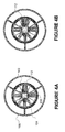
Fig. 4A is a pictorial representation of a bottom view of an air duct in a standard position; -
Fig. 4B is a pictorial representation of a bottom view of the air duct ofFig. 4A with two control vanes deflected toward each other; -
Fig. 5A-B are pictorial representations of sides views of vanes deflected in tandem; and -
Fig. 5C-D are pictorial representations of sides views of vanes deflected in the manned according to the present application. - Ducted fan air-vehicles are known for their superior stationary aerodynamic hovering performance, three-dimensional precision position hold, low speed flights, precision vertical take-off and landing ("VTOL") and safe close-range operations. Ducted fan air-vehicles may be preprogrammed to perform operations autonomously, or they may be controlled by a human operator. Therefore, ducted fan air-vehicles may be unmanned aerial vehicles ("UAV").
- UAVs may have avionics equipment on board to control the flight and operation of the UAV. For instance, the avionics may control the direction, flight, stability compensation, and other aspects of flight control. Additionally, UAVs may carry a variety of equipment on board tailored to the mission the UAVs are assigned to accomplish. UAVs may carry sensors on board to obtain information about surroundings, or the UAVs may carry a payload to be deposited at a target site. The UAV engine to drive the UAV requires that fuel be carried on board the UAV. The avionics equipment, sensors, payload, and fuel may be stored on the UAV.
- In order to be effective and controllable in multiple flight conditions, ducted fan air-vehicles preferably have clean and attached air flow around the duct lip in the multiple flight conditions. Further, ducted fan air-vehicles preferably have a favorable center of gravity in order to be effective and controllable. A uniform inflow velocity profile into the fan is also desirable to minimize the acoustic signature of the duct-fan interaction.
- Flight control of ducted fan-based UAVs depends on large amounts of control authority, especially when maneuvering in unsteady or turbulent winds. The design of the present application makes it possible to obtain additional control authority in one direction, or about one rotational axis of a ducted fan vehicle that uses otherwise conventional control vanes at the rear of the duct.
- In a typical ducted fan air-vehicle, pairs of control vanes work together, or in tandem. The present application, however, uses de-coupled adjacent vanes. Each vane requires its own servo, or some other similar mechanism, to move independent of its neighboring vane surface. Using electric power, the servos provide mechanical torque to move and hold the control vanes in a certain position. Thus, the vanes move independently of each other. The leading edges of the control vanes may then be deflected toward each other, which generates a large drag force over that portion of the duct.
- Referring to
Figure 2A , a ducted fan air-vehicle 100 is shown. The ducted fan air-vehicle 100 includes anair duct 102 having afan 104 located within or downstream from theair duct 102. The ducted fan air-vehicle may also include acenter body 106. Thecenter body 106 may be a housing that contains other components of the air-vehicle 100, such as anengine 107 for powering the air-vehicle 100, a camera, or additional components for air-vehicle operation, such as anavionics system 109. The ducted fan-air vehicle 100 is stabilized when it is on the ground bylanding gear 108. Although thelanding gear 108 shown in the Figures is ring shaped, alternate types of landing gear may be used. - The ducted fan air-
vehicle 100 may also include astator assembly 110. Thestator assembly 110 may be located just under thefan 104 in theair duct 102 to reduce or eliminate the swirl and torque produced by thefan 104 by providing the correct amount of anti-torque to counteract engine torque. Thestator assembly 110 may also add to the vehicle's structural integrity. - The ducted fan air-
vehicle 100 may also include a plurality of fixed ormoveable control vanes 112 for providing the necessary forces and moments for vehicle control. Thevanes 112 may be located under thefan 104 within theair duct 102. Thevanes 112 may be connected to theair duct 102 by control vane supports 117. Thevanes 112 may be placed slightly below an exit section of theair duct 102. Thevanes 112 are placed in the fan airflow and away from the vehicle center of gravity (CG) location. The farther away thevanes 112 are placed from the CG, the better they are at providing moments for vehicle attitude control. The vanes may also include moveable flap surfaces 114 at a trailingedge 115. The flap surfaces 114 deflect as thecontrol vanes 112 are deflected. The moveable flap surfaces 114 produce more lift than a single rigid surface. When leadingedges 116 ofcontrol vanes 112 are deflected toward each other, a large amount of drag can be generated. - In the present application, the surface of each control vane 112 (8 surfaces total) requires its own servo or method of independent actuation. A servo converts electrical signals to mechanical power. The
servo 118 may be mounted on, or internal to, thevanes 112 themselves, as shown inFig. 3A , or may move the vanes via a system of linkages if externally mounted as shown inFig. 3B . With each vane having itsown servo 118, thevanes 112 are free to move independently. Thevanes 112 may also generate large amounts of drag if theleading edges 116 of a vane pair are moved toward each other in a "closed" position, as shown inFigs. 2B ,4B , and5D . - Vehicle thrust may also be controlled to some degree by deflecting all four vane pairs 112 in a similar manner, simultaneously, to generate changes in overall vehicle thrust without changing the main fan speed or blade pitch angle. Since each vane has its own servo, the vanes can be used to produce pitch, roll, or yaw control moments to control the vehicle when operating in tandem (as shown in
Figs 5A and 5B ). Pitch, roll, and yaw moments are specific moments about the vehicle x, y, and z axis directions. This method of deflecting the vanes generates drag without any resulting forces in other directions, much like a drag brake on aircraft. Drag brakes have many different forms, but may be surfaces deployed to generate aerodynamic drag to help slow down an aircraft. In a similar manner, opposed vanes can generate aerodynamic drag to tailor thrust of the fan. Possible uses of this technique include small trim changes to thrust while in flight, or large thrust changes while on the ground as part of a rapid takeoff maneuver. - In operation, when the
vehicle 100 is flying, it may encounter a strong unsteady wind or gust, which may tend to cause the vehicle to tilt in a different direction than it was originally travelling. It is important that a ducted fan vehicle (as pictured inFig 1 ) is able to quickly tilt into the wind to stabilize its flight in unsteady conditions. To achieve the required nose-down tilt into the wind, the vehicle must overcome the inherent nose-up pitch moment present on the windward side of the duct lip. Therefore, tilting a ducted fan aircraft into the wind requires overcoming its natural tendency to pitch away from the oncoming wind. The present application gives thevehicle 100 more control authority to tilt in the direction that it needs to move in for station keeping and other mission tasks. - In order to provide more nose-down pitch moment to tilt the vehicle, the leading edge of two
control vanes 112 are deflected toward each other, which generates a large drag force on the front of theair duct 102. Only the pair ofvanes 112 in the direction of desired tilt are closed, as shown inFig. 4B . A flight control system, which may be part of theavionics system 109, controls the deflection of thevanes 112 by sending command signals to the servos. The flight control system is a collection of on-board electronics (sensors, computer, etc.), and is located wherever there is suitable space, such as in thecenter body 106. Some or all of the on-board electronics may also be located in theduct pod 113. - Another advantage of each vane having its own servo and being able to move independently is that the vehicle's thrust can be easily tailored. In an alternate embodiment, the same concept is used, but applied to all four control vane pairs. In this manner, the
control vanes 112 provide a level of thrust control of the aircraft, independent of controlling the main lift fan's speed or blade pitch angle. This method may be useful for fine control of thrust levels for precision maneuvering or in cases when the fan speed or blade pitch angle may not respond quickly enough in turbulent wind conditions. Another situation may occur at takeoff when it is desired to provide maximum thrust as quickly as possible for rapid takeoff. With the four vane pairs in a "closed" position, the vehicle thrust is limited even though the fan may be running at full design speed. Rapid takeoff is then enabled by moving vanes quickly to zero deflection to provide full fan thrust. - The present application is counterintuitive because independent control vanes weigh more than pairs of vanes because there are more servos. While it is true that additional servos are required for this type of control system design (one per vane surface), at least two advantages over the prior art are gained by having servos for each vane. The first is that smaller servos can be used to help offset the required increase in weight, power, and space requirements. The second is system redundancy; if one servo fails, the vehicle has a better chance of retaining control compared to the conventional design, as there is not a complete loss of functionality of one vane pair.
- While certain features and embodiments of the present application have been described in detail herein, it is to be understood that the application encompasses all modifications and enhancements within the scope and spirit of the following claims.
Claims (8)
- A ducted fan air-vehicle comprising:an air duct;a fan;a center body;a plurality of control vanes located within or downstream from the air duct, each control vane having a leading edge;a separate servo for each control vane for independently controlling each vane.
- The ducted fan air-vehicle of claim 1 wherein each vane includes a flap surface.
- The ducted fan air-vehicle of claim 1 wherein each servo is mounted onto each control vane.
- The ducted fan air-vehicle of claim 1 wherein each servo is located outside of each control vane.
- The ducted fan air-vehicle of claim 1 wherein each control vane is connected to the air duct by a control vane support.
- The ducted fan air-vehicle of claim 1 wherein the center body includes an engine, a camera, or an avionics system.
- The ducted fan air-vehicle of claim 1 wherein the leading edges of two adjacent control vanes are deflected toward each other to generate a drag force on the air duct.
- The ducted fan air-vehicle of claim 7 further comprising a flight control system for controlling the deflection of the control vanes.
Applications Claiming Priority (1)
| Application Number | Priority Date | Filing Date | Title |
|---|---|---|---|
| US12/359,407 US8348190B2 (en) | 2009-01-26 | 2009-01-26 | Ducted fan UAV control alternatives |
Publications (1)
| Publication Number | Publication Date |
|---|---|
| EP2210812A2 true EP2210812A2 (en) | 2010-07-28 |
Family
ID=42104591
Family Applications (1)
| Application Number | Title | Priority Date | Filing Date |
|---|---|---|---|
| EP09176566A Withdrawn EP2210812A2 (en) | 2009-01-26 | 2009-11-19 | Ducted fan UAV control system |
Country Status (3)
| Country | Link |
|---|---|
| US (1) | US8348190B2 (en) |
| EP (1) | EP2210812A2 (en) |
| JP (1) | JP2010168034A (en) |
Cited By (1)
| Publication number | Priority date | Publication date | Assignee | Title |
|---|---|---|---|---|
| EP3957560A1 (en) * | 2017-12-07 | 2022-02-23 | Zipair | Improved flight systems and methods of use thereof |
Families Citing this family (10)
| Publication number | Priority date | Publication date | Assignee | Title |
|---|---|---|---|---|
| CA2863165A1 (en) * | 2011-11-16 | 2013-05-23 | Radeus Labs, Inc. | Methods and apparatus for vertical/short takeoff and landing |
| US20130126680A1 (en) * | 2011-11-17 | 2013-05-23 | Honeywell International Inc. | Unmanned air vehicle fault tolerant flight control system and method |
| KR101470487B1 (en) * | 2012-11-23 | 2014-12-11 | 임예현 | Smart fan |
| ITRM20130473A1 (en) * | 2013-08-12 | 2013-11-11 | Unit 1 Srl | CONVERTIPLATE WITH NEW TECHNICAL AND AERODYNAMIC SOLUTIONS THAT CAN MAKE THE MEANS ALSO IN SAFE AND ULTRA-LIGHT AIRCRAFT SOLUTIONS |
| USD766159S1 (en) * | 2015-08-27 | 2016-09-13 | Skycatch, Inc. | Landing gear for an unmanned aerial vehicle |
| US11021242B2 (en) | 2016-08-11 | 2021-06-01 | The Hayden Effect, Llc | Apparatus for providing rail-based vertical short takeoff and landing and operational control |
| US11208197B2 (en) | 2017-03-31 | 2021-12-28 | Heka Aero LLC | Gimbaled fan |
| US11104432B2 (en) | 2018-10-09 | 2021-08-31 | Stefano Rivellini | Bent tube ducted fan drone |
| US11821338B2 (en) * | 2019-09-11 | 2023-11-21 | Alexandru Balan | 360° advanced rotation system |
| CN112623209B (en) * | 2020-12-31 | 2023-04-18 | 上海海洋大学 | Main and auxiliary double-rotor aircraft |
Family Cites Families (77)
| Publication number | Priority date | Publication date | Assignee | Title |
|---|---|---|---|---|
| US2929580A (en) * | 1956-06-18 | 1960-03-22 | Piasecki Aircraft Corp | Aircraft for vertical or short takeoff, and integrated propulsion lifting and propeller slip stream deflecting unit therefor |
| US2968453A (en) * | 1958-01-13 | 1961-01-17 | Edward F Golding | Ducted fan aircraft |
| US3861822A (en) | 1974-02-27 | 1975-01-21 | Gen Electric | Duct with vanes having selectively variable pitch |
| US4071207A (en) * | 1975-09-09 | 1978-01-31 | Piasecki Aircraft Corporation | Vertical take-off aircraft |
| US4279568A (en) | 1978-10-16 | 1981-07-21 | United Technologies Corporation | Vane angle control |
| GB8404752D0 (en) | 1984-02-23 | 1984-03-28 | Ici Plc | Vehicles |
| US4652208A (en) | 1985-06-03 | 1987-03-24 | General Electric Company | Actuating lever for variable stator vanes |
| US4795111A (en) | 1987-02-17 | 1989-01-03 | Moller International, Inc. | Robotic or remotely controlled flying platform |
| JPH01254489A (en) * | 1988-04-05 | 1989-10-11 | Mitsubishi Heavy Ind Ltd | Aircraft having two vertical trail planes |
| JPH03504408A (en) | 1989-02-27 | 1991-09-26 | ユナイテッド・テクノロジーズ・コーポレイション | Gas turbine engine control device |
| US5152478A (en) | 1990-05-18 | 1992-10-06 | United Technologies Corporation | Unmanned flight vehicle including counter rotating rotors positioned within a toroidal shroud and operable to provide all required vehicle flight controls |
| US5190439A (en) | 1991-07-15 | 1993-03-02 | United Technologies Corporation | Variable vane non-linear schedule for a gas turbine engine |
| US5150857A (en) | 1991-08-13 | 1992-09-29 | United Technologies Corporation | Shroud geometry for unmanned aerial vehicles |
| US5295643A (en) * | 1992-12-28 | 1994-03-22 | Hughes Missile Systems Company | Unmanned vertical take-off and landing, horizontal cruise, air vehicle |
| US5390877A (en) * | 1993-06-25 | 1995-02-21 | Rolls Royce Plc | Vectorable nozzle for aircraft |
| US5505407A (en) * | 1993-09-09 | 1996-04-09 | Fran Rich Chi Associates | Air-land vehicle |
| US5575438A (en) | 1994-05-09 | 1996-11-19 | United Technologies Corporation | Unmanned VTOL ground surveillance vehicle |
| US5695153A (en) | 1995-11-16 | 1997-12-09 | Northrop Grumman Corporation | Launcher system for an unmanned aerial vehicle |
| US6318668B1 (en) * | 1996-08-02 | 2001-11-20 | Allison Advanced Development Company | Thrust vectoring techniques |
| US6105901A (en) * | 1996-08-02 | 2000-08-22 | Allison Engine Co., Inc. | Thrust vectoring system |
| JPH11115896A (en) * | 1997-10-17 | 1999-04-27 | Komatsu Ltd | Unmanned and freely controlled flying body with low speed |
| WO2000015497A2 (en) | 1998-08-27 | 2000-03-23 | Nicolae Bostan | Gyrostabilized self propelled aircraft |
| WO2000040464A2 (en) | 1998-12-11 | 2000-07-13 | Moller International, Inc. | Stabilizing control apparatus for robotic or remotely controlled flying platform |
| US6170778B1 (en) | 1999-04-22 | 2001-01-09 | Sikorsky Aircraft Corporation | Method of reducing a nose-up pitching moment on a ducted unmanned aerial vehicle |
| US6422508B1 (en) | 2000-04-05 | 2002-07-23 | Galileo Group, Inc. | System for robotic control of imaging data having a steerable gimbal mounted spectral sensor and methods |
| US6622090B2 (en) | 2000-09-26 | 2003-09-16 | American Gnc Corporation | Enhanced inertial measurement unit/global positioning system mapping and navigation process |
| IL138695A (en) | 2000-09-26 | 2004-08-31 | Rafael Armament Dev Authority | Unmanned mobile device |
| US6848649B2 (en) | 2000-10-03 | 2005-02-01 | Charles Gilpin Churchman | V/STOL biplane aircraft |
| WO2003004353A2 (en) | 2001-07-06 | 2003-01-16 | The Charles Stark Draper Laboratory, Inc. | Vertical takeoff and landing aerial vehicle |
| US6721646B2 (en) | 2001-09-27 | 2004-04-13 | Ernest A. Carroll | Unmanned aircraft with automatic fuel-to-air mixture adjustment |
| US6847865B2 (en) | 2001-09-27 | 2005-01-25 | Ernest A. Carroll | Miniature, unmanned aircraft with onboard stabilization and automated ground control of flight path |
| US6824095B2 (en) | 2001-11-29 | 2004-11-30 | Youbin Mao | VSTOL vehicle |
| US6665594B1 (en) | 2001-12-13 | 2003-12-16 | The United States Of America As Represented By The Secretary Of The Navy | Plug and play modular mission payloads |
| US7032861B2 (en) | 2002-01-07 | 2006-04-25 | Sanders Jr John K | Quiet vertical takeoff and landing aircraft using ducted, magnetic induction air-impeller rotors |
| US20040094662A1 (en) | 2002-01-07 | 2004-05-20 | Sanders John K. | Vertical tale-off landing hovercraft |
| US6808140B2 (en) | 2002-02-08 | 2004-10-26 | Moller Paul S | Vertical take-off and landing vehicles |
| US6502787B1 (en) | 2002-02-22 | 2003-01-07 | Micro Autonomous Systems Llc | Convertible vertical take-off and landing miniature aerial vehicle |
| US6575402B1 (en) | 2002-04-17 | 2003-06-10 | Sikorsky Aircraft Corporation | Cooling system for a hybrid aircraft |
| US6694228B2 (en) | 2002-05-09 | 2004-02-17 | Sikorsky Aircraft Corporation | Control system for remotely operated vehicles for operational payload employment |
| CA2490886A1 (en) | 2002-06-28 | 2004-01-08 | Ashley Christopher Bryant | Ducted air power plant |
| AU2003264929A1 (en) | 2002-09-23 | 2004-04-08 | Stefan Reich | Measuring and stabilising system for machine-controllable vehicles |
| US6873886B1 (en) | 2002-11-27 | 2005-03-29 | The United States Of America As Represented By The Secretary Of The Navy | Modular mission payload control software |
| US7000883B2 (en) | 2003-01-17 | 2006-02-21 | The Insitu Group, Inc. | Method and apparatus for stabilizing payloads, including airborne cameras |
| US6712312B1 (en) | 2003-01-31 | 2004-03-30 | The United States Of America As Represented By The Secretary Of The Navy | Reconnaissance using unmanned surface vehicles and unmanned micro-aerial vehicles |
| SE0300871D0 (en) | 2003-03-27 | 2003-03-27 | Saab Ab | Waypoint navigation |
| ITTO20030588A1 (en) | 2003-07-30 | 2005-01-31 | Fiat Ricerche | FLYING CAR. |
| US6813559B1 (en) | 2003-10-23 | 2004-11-02 | International Business Machines Corporation | Orbiting a waypoint |
| US7231294B2 (en) | 2003-10-23 | 2007-06-12 | International Business Machines Corporation | Navigating a UAV |
| WO2005123502A2 (en) | 2003-12-12 | 2005-12-29 | Advanced Ceramics Research, Inc. | Unmanned vehicle |
| US7289906B2 (en) | 2004-04-05 | 2007-10-30 | Oregon Health & Science University | Navigation system applications of sigma-point Kalman filters for nonlinear estimation and sensor fusion |
| US7262395B2 (en) | 2004-05-19 | 2007-08-28 | Derek Bilyk | Expendable sonobuoy flight kit with aerodynamically assisted sonobuoy separation |
| EP1612632B1 (en) | 2004-07-03 | 2009-01-07 | Saab Ab | A system and method for in-flight control of an aerial vehicle |
| US7228227B2 (en) | 2004-07-07 | 2007-06-05 | The Boeing Company | Bezier curve flightpath guidance using moving waypoints |
| US7302316B2 (en) | 2004-09-14 | 2007-11-27 | Brigham Young University | Programmable autopilot system for autonomous flight of unmanned aerial vehicles |
| WO2007001372A2 (en) | 2004-09-17 | 2007-01-04 | Aurora Flight Sciences | Ducted spinner for engine cooling |
| DE202004017679U1 (en) | 2004-11-15 | 2006-03-23 | Dolmar Gmbh | Starting brake for a hedge trimmer |
| US7512462B2 (en) | 2004-11-16 | 2009-03-31 | Northrop Grumman Corporation | Automatic contingency generator |
| US20060287824A1 (en) | 2005-01-29 | 2006-12-21 | American Gnc Corporation | Interruption free navigator |
| US7658346B2 (en) | 2005-02-25 | 2010-02-09 | Honeywell International Inc. | Double ducted hovering air-vehicle |
| US7520466B2 (en) | 2005-03-17 | 2009-04-21 | Nicolae Bostan | Gyro-stabilized air vehicle |
| US7946528B2 (en) | 2005-04-15 | 2011-05-24 | Urban Aeronautics, Ltd. | Flight control system especially suited for VTOL vehicles |
| US7748486B2 (en) | 2005-06-09 | 2010-07-06 | Honeywell International, Inc. | Landing gear for a hovercraft |
| US7962252B2 (en) | 2005-06-20 | 2011-06-14 | The United States Of America As Represented By The Administrator Of The National Aeronautics And Space Administration | Self-contained avionics sensing and flight control system for small unmanned aerial vehicle |
| US20070228214A1 (en) | 2005-09-26 | 2007-10-04 | Honeywell International Inc. | Autonomous launch pad for micro air vehicles |
| AU2005338333A1 (en) | 2005-11-15 | 2007-05-24 | Bell Helicopter Textron, Inc. | Control system for automatic circle flight |
| FR2894368B1 (en) | 2005-12-07 | 2008-01-25 | Thales Sa | DEVICE AND METHOD FOR AUTOMATED CONSTRUCTION OF EMERGENCY TRACK FOR AIRCRAFT |
| US7469725B2 (en) | 2006-02-22 | 2008-12-30 | Honeywell International Inc. | Method and apparatus for accurately delivering a predetermined amount of fuel to a vehicle |
| US7510142B2 (en) | 2006-02-24 | 2009-03-31 | Stealth Robotics | Aerial robot |
| US7841563B2 (en) | 2006-03-27 | 2010-11-30 | Honeywell International Inc. | Ducted fan air data system |
| US20070244608A1 (en) | 2006-04-13 | 2007-10-18 | Honeywell International Inc. | Ground control station for UAV |
| US20070262195A1 (en) | 2006-05-11 | 2007-11-15 | Robert Bulaga | UAV With Control and Stability System |
| US7720577B2 (en) | 2006-05-17 | 2010-05-18 | The Boeing Company | Methods and systems for data link front end filters for sporadic updates |
| US7702460B2 (en) | 2006-06-17 | 2010-04-20 | Northrop Grumman Guidance And Electronics Company, Inc. | Estimate of relative position between navigation units |
| US7967255B2 (en) | 2006-07-27 | 2011-06-28 | Raytheon Company | Autonomous space flight system and planetary lander for executing a discrete landing sequence to remove unknown navigation error, perform hazard avoidance and relocate the lander and method |
| US7840352B2 (en) | 2006-09-05 | 2010-11-23 | Honeywell International Inc. | Method and system for autonomous vehicle navigation |
| US7693617B2 (en) | 2006-09-19 | 2010-04-06 | The Boeing Company | Aircraft precision approach control |
| US20080078865A1 (en) | 2006-09-21 | 2008-04-03 | Honeywell International Inc. | Unmanned Sensor Placement In A Cluttered Terrain |
-
2009
- 2009-01-26 US US12/359,407 patent/US8348190B2/en not_active Expired - Fee Related
- 2009-11-19 EP EP09176566A patent/EP2210812A2/en not_active Withdrawn
- 2009-11-24 JP JP2009266454A patent/JP2010168034A/en active Pending
Cited By (1)
| Publication number | Priority date | Publication date | Assignee | Title |
|---|---|---|---|---|
| EP3957560A1 (en) * | 2017-12-07 | 2022-02-23 | Zipair | Improved flight systems and methods of use thereof |
Also Published As
| Publication number | Publication date |
|---|---|
| JP2010168034A (en) | 2010-08-05 |
| US20100187369A1 (en) | 2010-07-29 |
| US8348190B2 (en) | 2013-01-08 |
Similar Documents
| Publication | Publication Date | Title |
|---|---|---|
| US8348190B2 (en) | Ducted fan UAV control alternatives | |
| AU2020332673B2 (en) | Separated lift-thrust VTOL aircraft with articulated rotors | |
| US20170158320A1 (en) | Unmanned aerial system | |
| US8220737B2 (en) | VTOL aerial vehicle | |
| US9120560B1 (en) | Vertical take-off and landing aircraft | |
| US9682774B2 (en) | System, apparatus and method for long endurance vertical takeoff and landing vehicle | |
| US6592071B2 (en) | Flight control system for a hybrid aircraft in the lift axis | |
| EP2991897B1 (en) | Vertical takeoff and landing (vtol) air vehicle | |
| US6431494B1 (en) | Flight control system for a hybrid aircraft in the roll axis | |
| US20160244159A1 (en) | Controlled Take-Off And Flight System Using Thrust Differentials | |
| EP0696983B1 (en) | Ancillary aerodynamic structures for an unmanned aerial vehicle having ducted, coaxial counter-rotating rotors | |
| US7118340B2 (en) | Swashplate and pitch link arrangement for a coaxial counter rotating rotor system | |
| US20060284002A1 (en) | Unmanned Urban Aerial Vehicle | |
| EP2193994A2 (en) | UAV ducted fan swept and lean stator design | |
| US6474603B1 (en) | Flight control system for a hybrid aircraft in the pitch axis | |
| EP3725680B1 (en) | Multimodal unmanned aerial systems having tiltable wings | |
| US20150136897A1 (en) | Aircraft, preferably unmanned | |
| CN112004746A (en) | Autonomous flight ambulance | |
| AU2348292A (en) | Shroud geometry for unmanned aerial vehicles | |
| US8511602B2 (en) | Differential vane vehicle control | |
| US6478262B1 (en) | Flight control system for a hybrid aircraft in the yaw axis | |
| US8104707B1 (en) | X-vane configuration in a ducted-fan aerial vehicle | |
| CN107444606B (en) | Novel aircraft and aircraft system | |
| CN112722264B (en) | Tail sitting type vertical take-off and landing unmanned aerial vehicle | |
| NL1040979B1 (en) | Air vehicle. |
Legal Events
| Date | Code | Title | Description |
|---|---|---|---|
| PUAI | Public reference made under article 153(3) epc to a published international application that has entered the european phase |
Free format text: ORIGINAL CODE: 0009012 |
|
| 17P | Request for examination filed |
Effective date: 20091119 |
|
| AK | Designated contracting states |
Kind code of ref document: A2 Designated state(s): AT BE BG CH CY CZ DE DK EE ES FI FR GB GR HR HU IE IS IT LI LT LU LV MC MK MT NL NO PL PT RO SE SI SK SM TR |
|
| AX | Request for extension of the european patent |
Extension state: AL BA RS |
|
| STAA | Information on the status of an ep patent application or granted ep patent |
Free format text: STATUS: THE APPLICATION HAS BEEN WITHDRAWN |
|
| 18W | Application withdrawn |
Effective date: 20140415 |