EP2210642A2 - Magnetic field applicator - Google Patents
Magnetic field applicator Download PDFInfo
- Publication number
- EP2210642A2 EP2210642A2 EP10000598A EP10000598A EP2210642A2 EP 2210642 A2 EP2210642 A2 EP 2210642A2 EP 10000598 A EP10000598 A EP 10000598A EP 10000598 A EP10000598 A EP 10000598A EP 2210642 A2 EP2210642 A2 EP 2210642A2
- Authority
- EP
- European Patent Office
- Prior art keywords
- magnetic field
- fields
- applicator according
- carrier
- field applicator
- Prior art date
- Legal status (The legal status is an assumption and is not a legal conclusion. Google has not performed a legal analysis and makes no representation as to the accuracy of the status listed.)
- Granted
Links
Images


Classifications
-
- A—HUMAN NECESSITIES
- A61—MEDICAL OR VETERINARY SCIENCE; HYGIENE
- A61N—ELECTROTHERAPY; MAGNETOTHERAPY; RADIATION THERAPY; ULTRASOUND THERAPY
- A61N2/00—Magnetotherapy
- A61N2/02—Magnetotherapy using magnetic fields produced by coils, including single turn loops or electromagnets
-
- A—HUMAN NECESSITIES
- A61—MEDICAL OR VETERINARY SCIENCE; HYGIENE
- A61N—ELECTROTHERAPY; MAGNETOTHERAPY; RADIATION THERAPY; ULTRASOUND THERAPY
- A61N2/00—Magnetotherapy
- A61N2/06—Magnetotherapy using magnetic fields produced by permanent magnets
Definitions
- An embodiment of a magnetic field applicator comprises a planar carrier which is divided into a number of fields by at least two intersecting mechanically defined folding lines or divided and foldable along the folding lines.
- at least two fields from the number of fields have a magnetic field source which in each case comprises an electrical conductor suitable for generating a magnetic field.
- adjacent panels may be interconnected by hinges or hinges whose axes define the fold lines.
- hinge any mechanical element is to be understood which allows a point of rotation about an axis of the element.
- a band is to be seen, which differs from the hinge substantially in that here arranged on the respective fields of the band members are separable.
- a rotational angle of the hinge or belt is substantially unlimited so that folding is not limited to a folding direction by the hinge or belt.
- the electrical conductors in addition to heat generation suitable.
- one of the electrical conductors is preferably designed such that its electrical resistance converts at least part of the energy which is supplied to the electrical conductor as current or voltage into heat.
- the generated heat can be used to support the effects of the continuing electromagnetic field on the living tissue.
- At least one of the magnetic field sources additionally has a permanent magnet.
- a magnetic basic field of a static type which acts together with the electromagnetic alternating field generated during operation of the magnetic field applicator.
- the permanent magnets are arranged differently so that their magnetic fields do not cancel each other out differently.
- the seams 31 may also be mechanical Elements are provided which allow a folding of the carrier 1 along the folding line.
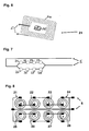
- FIG. 3A as an embodiment of such a mechanical element, the connection of two panels 41, 42 designed as panels is made as a hinge 32, which is movable about respective axes 33 of the hinge 32.
- the folding line 3a is defined by the axes 33 of the hinges 32.
- the hinges 32 In order to allow the most flexible possible folding of the magnetic field applicator, it is desirable that the hinges 32 have the largest possible angle of rotation, preferably of nearly 360 °, to allow the fields 41, 42 to fold over one another in both directions. If hinges 32 are used to connect several or all fields of the planar support 1, it is favorable to arrange the hinges in such a way that they do not come to rest on one another when folding over the fields. Thus, the smallest possible folding height of the carrier 1 can be achieved.
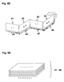
- FIGS. 9A to 9E a folding operation of the planar support 1 with corresponding resulting magnetic fields.
- Figure 9A shows an initially unfolded carrier with fields 41 to 48 and folding lines 3a, 3b.
- FIG. 8 are shown in the fields 41, 43, 46, 48 magnetic fields of positive polarity in the operation of the magnetic field applicator.
- the fields 42, 44, 45, 47 have a negative polarity of the magnetic field, ie inversely to the respectively adjacent fields.
- the polarity of the magnetic fields is also assumed in the plan view of the carrier 1. In a view from below, all polarities would be reversed.
- a first folding operation is indicated along the folding line 3b by the curved arrow.
Landscapes
- Health & Medical Sciences (AREA)
- Engineering & Computer Science (AREA)
- Biomedical Technology (AREA)
- Nuclear Medicine, Radiotherapy & Molecular Imaging (AREA)
- Radiology & Medical Imaging (AREA)
- Life Sciences & Earth Sciences (AREA)
- Animal Behavior & Ethology (AREA)
- General Health & Medical Sciences (AREA)
- Public Health (AREA)
- Veterinary Medicine (AREA)
- Magnetic Treatment Devices (AREA)
- Packaging Of Annular Or Rod-Shaped Articles, Wearing Apparel, Cassettes, Or The Like (AREA)
- Electrotherapy Devices (AREA)
Abstract
Description
Die Erfindung betrifft einen Magnetfeldapplikator mit mehreren zur Erzeugung eines Magnetfelds geeigneten elektrischen Leitern.The invention relates to a magnetic field applicator with a plurality of electrical conductors suitable for generating a magnetic field.
Magnetfeldapplikatoren werden in verschiedenen Ausführungsformen in Form von Matten hergestellt, in alternativen Ausführungsformen sind Magnetfeldapplikatoren mit einem Gehäuse ausgeführt. Magnetfeldapplikatoren dienen beispielsweise der nicht-invasiven therapeutischen Behandlung von lebendem Gewebe. Hierbei ist sowohl die Behandlung von menschlichen Körpern, aber auch von Tieren möglich.Magnetic field applicators are manufactured in various embodiments in the form of mats, in alternative embodiments, magnetic field applicators are implemented with a housing. Magnetic field applicators serve, for example, for the non-invasive therapeutic treatment of living tissue. Here, both the treatment of human bodies, but also of animals is possible.
Magnetfeldapplikatoren in Form von Matten eignen sich insbesondere für die Ganzkörperbehandlung am Menschen. Für Teilkörperbehandlungen können unter anderem die übrigen genannten Ausführungsformen verwendet werden.Magnetic field applicators in the form of mats are particularly suitable for the whole-body treatment of humans. For part body treatments, among other things, the other embodiments mentioned can be used.
Die verschiedenen Magnetfeldapplikatoren weisen üblicherweise elektrische Leiter auf, welche an ein Steuergerät angeschlossen werden. Dieses gibt einen zeitlich veränderlichen elektrischen Strom bzw. eine entsprechende Spannung an die elektrischen Leiter ab, um dadurch ein sich zeitlich veränderndes Magnetfeld zu erzeugen, welches vom Magnetfeldapplikator abgegeben wird. Wenn das so erzeugte Magnetfeld auf lebendes Gewebe wirkt, ergibt sich in Abhängigkeit des zeitlichen Magnetfeldintensitätsverlaufs die beabsichtigte therapeutische Wirkung im Gewebe. Diese gewünschte Wirkung wird auch als Elektro-Magnetfeldbehandlung bezeichnet.The various magnetic field applicators usually have electrical conductors which are connected to a control unit. This emits a time-varying electrical current or a corresponding voltage to the electrical conductors, thereby generating a time-varying magnetic field, which is emitted by the magnetic field applicator. When the magnetic field thus generated acts on living tissue, the intended therapeutic effect in the tissue results, depending on the temporal magnetic field intensity profile. This desired effect is also referred to as electro-magnetic field treatment.
Ein mattenförmiger Magnetfeldapplikator ist beispielsweise aus der
Eine Matte für Ganzkörperbehandlung ist jedoch nicht für die Behandlung kleinerer Körperregionen geeignet, da bei herkömmlichen Matten das erzeugte Magnetfeld mit auf die ganze Mattenfläche verteilter Intensität abgegeben wird. Aus diesem Grund werden vielfach kleinere Matten eingesetzt, die in ihrer Größe für eine Teilkörperbehandlung eingerichtet sind. Derartige kleinere Matten können zwar unter Umständen mit dem gleichen Steuergerät betrieben werden, jedoch ist es notwendig, für verschiedene Anwendungsfälle kleinere Matten verschiedener Größe bereitzustellen. Dadurch, dass für verschiedene Behandlungsformen unterschiedlich große Magnetfeldapplikatoren notwendig sein können, entstehen sowohl in der Produktion als auch für den Endverbraucher hohe Kosten.However, a whole-body treatment mat is not suitable for treating smaller body regions, as in conventional mats, the generated magnetic field is delivered with intensity distributed throughout the mat surface. For this reason, much smaller mats are used, which are set up in size for a partial body treatment. Although such smaller mats may be operated with the same controller, it is necessary to provide smaller mats of different sizes for different applications. The fact that different sized magnetic field applicators may be necessary for different treatment forms, both in production and for the end user high costs.
Magnetfeldapplikatoren werden zu Transport und Aufbewahrung üblicherweise ohne spezielle Vorgaben zusammengerollt oder beliebig gefaltet und beispielsweise zusammen mit entsprechenden Steuergeräten und/oder weiteren Applikatorformen in entsprechend dimensionierte Behältnisse verpackt. Beim Zusammenrollen oder beliebigen Falten durch den Anwender kann es jedoch zu Beschädigungen oder Veränderungen der Leiterbahnen kommen, so dass die gewünschte Magnetfelderzeugung verändert oder sogar unmöglich wird.Magnetic field applicators are usually rolled up for transport and storage without special specifications or folded in any way and, for example, packed together with corresponding control devices and / or other applicator molds in correspondingly dimensioned containers. When rolling up or any folding by the user, however, it may cause damage or changes in the tracks, so that the desired magnetic field generation is changed or even impossible.
Eine zu lösende Aufgabe besteht demnach darin, einen Magnetfeldapplikator bereitzustellen, der sich in seiner Anwendung durch verringerten Aufwand und erhöhte Flexibilität auszeichnet.A problem to be solved is therefore to provide a magnetic field applicator, which is characterized in its application by reduced effort and increased flexibility.
Diese Aufgabe wird durch den Gegenstand des unabhängigen Patentanspruchs gelöst. Weiterbildungen und verschiedene Ausführungsformen sind in den abhängigen Patentansprüchen gekennzeichnet.This object is solved by the subject matter of the independent claim. Further developments and various embodiments are characterized in the dependent claims.
Ein Ausführungsbeispiel eines Magnetfeldapplikators umfasst einen flächigen Träger, der durch wenigstens zwei sich schneidende mechanisch definierte Faltungslinien in eine Anzahl Felder geteilt bzw. unterteilt und entlang der Faltungslinien faltbar ist. Hierbei weisen wenigstens zwei Felder aus der Anzahl von Feldern eine Magnetfeldquelle auf, die jeweils einen zur Erzeugung eines Magnetfelds geeigneten elektrischen Leiter umfasst.An embodiment of a magnetic field applicator comprises a planar carrier which is divided into a number of fields by at least two intersecting mechanically defined folding lines or divided and foldable along the folding lines. In this case, at least two fields from the number of fields have a magnetic field source which in each case comprises an electrical conductor suitable for generating a magnetic field.
Der flächige Träger, der beispielsweise als Matte ausgeführt ist, lässt sich entlang der mechanisch definierten Faltungslinien so falten, dass die durch die Faltungslinien gebildeten Felder in verschiedenen Formen oder Ausgestaltungen übereinander zu liegen kommen. Beispielsweise weist der Träger bzw. die Matte eine Ober- und eine Unterschicht auf, zwischen denen die Magnetfeldquellen angeordnet sind. Durch die Faltungslinien lässt sich beispielsweise ein flächiger Träger in Körpergröße durch die Faltung gezielt und definiert verkleinern. Da die Felder nicht in sich sondern lediglich entlang der Faltungslinien gefaltet werden, wird eine Beschädigung der elektrischen Leiter zur Magnetfelderzeugung in den jeweiligen Feldern verhindert.The flat support, which is designed, for example, as a mat, can be folded along the mechanically defined folding lines in such a way that the fields formed by the folding lines come to lie one above the other in different shapes or configurations. For example, the carrier or the mat has an upper and an underlayer, between which the magnetic field sources are arranged. By means of the folding lines, it is possible, for example, to narrow down a planar carrier in body size by the folding in a targeted and defined manner. Since the fields are not folded in themselves but only along the fold lines, damage to the electrical conductors for magnetic field generation in the respective fields is prevented.
Wenn bei einem Magnetfeldapplikator in gefaltetem Zustand mehrere Felder mit entsprechenden elektrischen Leitern übereinander liegen, wirken im Betrieb des Magnetfeldapplikators die von den übereinander liegenden Feldern erzeugten Magnetfelder zusammen. Dies kann bei entsprechender Ansteuerung der Felder ausgenutzt werden, wenn der Magnetfeldapplikator in gefaltetem Zustand betrieben wird. Ein solcher Magnetfeldapplikator ist somit flexibler einsetzbar.In the case of a magnetic field applicator in the folded state, when a plurality of arrays are arranged one above the other with corresponding electrical conductors, the magnetic fields generated by the superposed fields act together during operation of the magnetic field applicator. This can be exploited with appropriate control of the fields when the magnetic field applicator is operated in the folded state. Such a magnetic field applicator is thus more flexible.
Die Magnetfeldquellen sind derart in den Feldern angeordnet, dass sich Magnetfeldintensitäten der Magnetfeldquellen übereinander gefalteter Felder bei einer Faltung des Trägers erhöhend überlagern. Wenn beispielsweise zwei benachbarte Felder gleiche Magnetfeldintensität erzeugen, kann sich die Magnetfeldintensität bei einer Faltung dieser Felder und entsprechender Polarität der der einzelnen Magnetfeld erzeugenden Leiter näherungsweise verdoppeln. Werden weitere Felder gleicher Intensität bei richtiger Polarität übereinander gefaltet, kann es auch zu einer Verdreifachung bzw. Vervierfachung usw. kommen. Alternativ kann auch die Intensität des elektrischen Stroms bzw. der elektrischen Spannung, welche zur Ansteuerung der elektrischen Leiter verwendet werden, in entsprechender Weise reduziert werden, um bei Übereinanderfaltung der Felder eine gewünschte Intensität zu erreichen. Somit lässt sich ein und derselbe Magnetfeldapplikator für verschiedene Anwendungen einsetzen, z.B. zur Ganzkörperbehandlung oder zur Behandlung von einzelnen Körperteilen, wobei der Einsatz von der Ansteuerung und der so erzeugten Intensität abhängen kann.The magnetic field sources are arranged in the fields such that magnetic field intensities of the magnetic field sources of superimposed folded fields are superimposed upon folding of the carrier. For example, if two adjacent fields produce the same magnetic field intensity, the magnetic field intensity at convolution of these fields and corresponding polarity may be that of the individual Approximately doubling the magnetic field generating conductor. If further fields of the same intensity are folded over each other with the correct polarity, it can also lead to a tripling or quadrupling, etc. Alternatively, the intensity of the electrical current or voltage used to drive the electrical conductors can also be correspondingly reduced in order to achieve a desired intensity when the fields are folded over one another. Thus, one and the same magnetic field applicator can be used for various applications, for example for whole body treatment or for the treatment of individual body parts, wherein the use of the control and the intensity thus generated may depend.
In einer Ausführungsform sind die Faltungslinien durch Nähte auf dem Träger gebildet. Somit stellen diese Nähte die mechanische Definition der Faltungslinien dar. Durch die Nähte ist vorzugsweise eine Dicke des flächigen Trägers an den Faltungslinien reduziert, so dass sich eine entsprechende Faltung leichter bewerkstelligen lässt.In one embodiment, the fold lines are formed by seams on the carrier. Thus, these seams represent the mechanical definition of the fold lines. The seams preferably reduce a thickness of the flat carrier at the fold lines, so that a corresponding fold can be accomplished more easily.
Alternativ oder zusätzlich können benachbarte Felder durch Scharniere oder Bänder miteinander verbunden sein, deren Achsen die Faltungslinien definieren. Hierbei soll unter Scharnier jedes mechanische Element verstanden werden, welches einen Drehpunkt um eine Achse des Elements ermöglicht. In ähnlicher Weise ist ein Band zu sehen, welches sich vom Scharnier im Wesentlichen dadurch unterscheidet, dass hier auf den jeweiligen Feldern angeordneten Glieder des Bandes trennbar sind. Vorzugsweise ist ein Drehwinkel das Scharniers oder Bandes im Wesentlichen unbegrenzt, so dass durch das Scharnier oder Band eine Faltung nicht auf eine Faltungsrichtung begrenzt ist.Alternatively or additionally, adjacent panels may be interconnected by hinges or hinges whose axes define the fold lines. Here, by hinge, any mechanical element is to be understood which allows a point of rotation about an axis of the element. Similarly, a band is to be seen, which differs from the hinge substantially in that here arranged on the respective fields of the band members are separable. Preferably, a rotational angle of the hinge or belt is substantially unlimited so that folding is not limited to a folding direction by the hinge or belt.
In einer Ausführungsform weisen benachbarte Felder Platten auf, die entlang einer der Faltungslinien flexibel miteinander verbunden sind. Anders ausgedrückt sind die Platten im Wesentlichen starr, während eine Faltung entlang der flexiblen Verbindung möglich ist. Die Platten sind hierbei beispielsweise biegsam, jedoch vorzugsweise nicht faltbar.In one embodiment, adjacent fields have plates, which are flexibly connected along one of the folding lines. In other words, the plates are substantially rigid while folding along the flexible connection is possible. The plates are for example flexible, but preferably not foldable.
In einem Ausführungsbeispiel sind die Faltungslinien sichtbar. Somit kann ein Anwender des Magnetfeldapplikators, der diesen falten will, sofort sehen, wie und wo er den flächigen Träger falten kann.In one embodiment, the fold lines are visible. Thus, a user of the magnetic field applicator who wants to fold it can immediately see how and where he can fold the sheet carrier.
In verschiedenen Ausführungsformen sind die elektrischen Leiter als flache Spulen ausgeführt. Beispielsweise sind die elektrischen Leiter mittels eines Druck- oder Ätzverfahrens auf einer Folie aufgebracht. Alternativ oder zusätzlich kann zumindest einer der elektrischen Leiter über Nähte in den Feldern fixiert sein. Dadurch ist bei einer Faltung des Trägers zusätzlich gewährleistet, dass der elektrische Leiter bzw. die magnetfelderzeugende Spule nicht verrutschen und die Eigenschaften des Magnetfelds nicht verändert werden.In various embodiments, the electrical conductors are designed as flat coils. For example, the electrical conductors are applied by means of a printing or etching process on a film. Alternatively or additionally, at least one of the electrical conductors may be fixed via seams in the fields. In this way, when the carrier is folded, it is additionally ensured that the electrical conductor or the coil generating the magnetic field does not slip and the properties of the magnetic field are not changed.
Die Spulen können in verschiedenen Kombinationen zwischen einem ersten und einem zweiten Anschluss in Reihe und/oder parallel geschaltet sein. Beispielsweise ist eine Serienschaltung einer Hälfte von entsprechenden Spulen parallel zu einer Serienschaltung der anderen Hälfte entsprechender Spulen geschaltet. Jedoch können auch andere Kombinationen von Serien- und Parallelschaltungen verwendet werden, wobei die jeweils gewählte Kombination bei der Zuführung eines entsprechenden Steuersignals an den ersten und zweiten Anschluss zu berücksichtigen ist, insbesondere in einer absoluten Höhe des zugeführten Stroms bzw. der angelegten Spannung.The coils may be connected in series and / or in parallel in various combinations between a first and a second terminal. For example, a series circuit of one half of respective coils is connected in parallel with a series connection of the other half of respective coils. However, other combinations of series and parallel circuits may be used, the combination chosen in each case being taken into account when supplying a corresponding control signal to the first and second terminals, in particular in terms of an absolute level of the supplied current or applied voltage.
In einem weiteren Ausführungsbeispiel sind die elektrischen Leiter zusätzlich zur Wärmeerzeugung geeignet. Hierbei wird einer der elektrischen Leiter vorzugsweise so ausgeführt, dass sein elektrischer Widerstand zumindest einen Teil der Energie, die dem elektrischen Leiter als Strom oder Spannung zugeführt wird, in Wärme umsetzt. Durch die erzeugte Wärme können die Effekte des weiterhin vorhandenen elektromagnetischen Felds auf das lebende Gewebe unterstützt werden.In a further embodiment, the electrical conductors in addition to heat generation suitable. In this case, one of the electrical conductors is preferably designed such that its electrical resistance converts at least part of the energy which is supplied to the electrical conductor as current or voltage into heat. The generated heat can be used to support the effects of the continuing electromagnetic field on the living tissue.
In einem weiteren Ausführungsbeispiel weist wenigstens eine der Magnetfeldquellen zusätzlich einen Permanentmagneten auf. Dadurch lässt sich ein magnetisches Grundfeld statischer Art erzeugen, welches zusammen mit dem im Betrieb des Magnetfeldapplikators erzeugten elektromagnetischen Wechselfeld wirkt. Vorzugsweise sind, wenn mehrere der Felder Permanentmagneten aufweisen, diese so angeordnet, dass bei einer Faltung des flächigen Trägeres eine erhöhende Überlagerung der jeweiligen statischen Magnetfelder erzielt wird. Anders ausgerückt sind in diesem Fall die Permanentmagneten so angeordnet, dass sich ihre Magnetfelder nicht gegenseitig auslöschen.In a further exemplary embodiment, at least one of the magnetic field sources additionally has a permanent magnet. As a result, it is possible to generate a magnetic basic field of a static type, which acts together with the electromagnetic alternating field generated during operation of the magnetic field applicator. Preferably, if a plurality of the fields have permanent magnets, these are arranged so that an increasing superimposition of the respective static magnetic fields is achieved during a folding of the flat carrier. In this case, the permanent magnets are arranged differently so that their magnetic fields do not cancel each other out differently.
Die Felder des Magnetfeldapplikators bzw. des flächigen Trägers sind in verschiedenen Ausführungsformen derart ausgestaltet, dass sie im Wesentlichen die gleichen Abmessungen aufweisen. In diesem Fall kann bei Übereinanderfaltung aller Felder eine einheitliche Form des gefalteten Träger erreicht werden.The fields of the magnetic field applicator or the planar carrier are configured in various embodiments such that they have substantially the same dimensions. In this case, when all fields are folded over, a uniform shape of the folded carrier can be achieved.
Die Magnetfeldquellen der einzelnen Felder können so gestaltet sein, dass durch sie im Betrieb unterschiedlich große Magnetfeldintensitäten erzeugt werden. Vorzugsweise sind die Magnetfeldquellen bzw. deren elektrische Leiter so dimensioniert und angeordnet, dass im Betrieb von ihnen die gleiche Magnetfeldintensität ausgeht. Beim Übereinanderfalten mit entsprechend vorgesehener Polarität der Magnetfeldquellen kommt es so im Wesentlichen zu einer ganzzahligen Vervielfachung der Magnetfeldintensität einer einzelnen Magnetfeldquelle.The magnetic field sources of the individual fields can be designed such that they generate different magnitudes of magnetic field during operation. Preferably, the magnetic field sources or their electrical conductors are dimensioned and arranged such that the same magnetic field intensity emanates from them during operation. When folding over with correspondingly provided polarity of the magnetic field sources, this essentially leads to a integral multiplication of the magnetic field intensity of a single magnetic field source.
In den beschriebenen Ausführungsbeispielen für den Magnetfeldapplikator kann das Material des Trägers beispielsweise einen textilen Stoff, ein Vlies, ein Gewebe, eine Membran, eine Kunststofffolie oder eine beliebige Kombination der genannten Materialien umfassen.In the described embodiments for the magnetic field applicator, the material of the carrier may comprise, for example, a textile fabric, a nonwoven fabric, a woven fabric, a membrane, a plastic film or any combination of said materials.
Nachfolgend wird die Erfindung in Ausführungsbeispielen unter Zuhilfenahme der Zeichnungen beschrieben. Gleiche oder gleichartige Elemente sind hierbei mit gleichen Bezugszeichen gekennzeichnet.The invention will be described in embodiments with the aid of the drawings. Identical or similar elements are identified by the same reference numerals.
Es zeigen:
Figur 1- ein Ausführungsbeipiel eines Magnetfeldapplikators,
- Figur 2
- eine beispielhafte Detailansicht des Magnetfeldapplikators,
- Figur 3
- Ausführungsbeispiele für die Verbindung zweier Felder,
- Figur 4
- ein Ausführungsbeispiel eines spulenförmigen elektrischen Leiters,
Figur 5- eine beispielhafte Detailansicht eines spulenförmigen elektrischen Leiters,
Figur 6- ein Ausführungsbeispiel eines Feldes mit Magnetfeldquellen,
- Figur 7
- eine beispielhafte schematische Anordnung für die Verschaltung mehrerer elektrischer Leiter
- Figur 8
- ein Ausführungsbeispiel einer Verschaltung von als Spulen ausgeführter elektrischer Leiter, und
- Figur 9
- ein Ausführungsbeispiel für einen Faltungsvorgang eines beispielhaften Magnetfeldapplikators.
- FIG. 1
- an embodiment of a magnetic field applicator,
- FIG. 2
- an exemplary detailed view of the magnetic field applicator,
- FIG. 3
- Exemplary embodiments for the connection of two fields,
- FIG. 4
- an embodiment of a coil-shaped electrical conductor,
- FIG. 5
- an exemplary detailed view of a coil-shaped electrical conductor,
- FIG. 6
- an embodiment of a field with magnetic field sources,
- FIG. 7
- an exemplary schematic arrangement for the interconnection of a plurality of electrical conductors
- FIG. 8
- An embodiment of an interconnection of designed as a coil electrical conductor, and
- FIG. 9
- an embodiment of a folding process of an exemplary magnetic field applicator.
Die Zahl und Anordnung der Felder kann auch variiert werden. Beispielsweise kann der flächige Träger 1 mehr als eine horizontale Faltungslinie 3b aufweisen. Ebenso ist es möglich, dass die im Ausführungsbeispiel dargestellte Zahl von 3 vertikalen Faltungslinien 3a verändert wird.The number and arrangement of the fields can also be varied. For example, the
Die Faltungslinien 3a, 3b sind mechanisch im oder auf dem flächigen Träger 1 definiert. Durch die mechanische Definition der Faltungslinien 3a, 3b lässt sich der Träger 1 gezielt falten, so dass es nicht zu einer Beschädigung der Magnetfeldquellen 21 bis 28 in den Feldern 41 bis 48 kommen kann. Eine derartige Faltung kann sowohl für die Aufbewahrung bzw. den Transport des Magnetfeldapplikators sinnvoll sein, als auch für den Betrieb des Magnetfeldapplikators.The
Im Betrieb kann der Magnetfeldapplikator nämlich sowohl im ungefalteten als auch im gefalteten Zustand verwendet werden. Bei Versorgung der elektrischen Leiter in den Magnetfeldquellen 21 bis 28 mit einem entsprechenden elektrischen Steuersignal wird von jeder der Magnetquellen ein Magnetfeld mit entsprechend dem Steuersignal variierender Magnetfeldintensität abgegeben. In ungefaltetem Zustand ergibt sich somit eine Abgabe des Magnetfelds über die Fläche des Trägers 1 verteilt. Im gefalteten Zustand des Trägers 1 können die einzelnen Magnetquellen 21 bis 28 in den Feldern 41 bis 48 derart ausgerichtet sein bzw. angesteuert werden, dass sich die Magnetfeldintensitäten übereinander liegender Felder verstärken. Hierbei ist zu berücksichtigen, dass die Magnetfeldquellen bei angenommener gleicher Magnetfeldintensität so wirken, dass sich das elektromagnetische Feld nicht gegenseitig auslöscht sondern erhöhend überlagert. Somit kann bei gleich bleibendem Steuersignal der Magnetfeldquellen durch Faltung des Trägers 1 eine entsprechend erhöhte Magnetfeldintensität erreicht werden. Alternativ kann zum Erreichen einer, nach Faltung, gleich bleibenden Magnetfeldintensität auf kleinerer Fläche das Steuersignal entsprechend angepasst, also beispielsweise in seiner Intensität verringert werden. Beispielsweise wird die Intensität um einen Faktor reduziert, der der Anzahl übereinander gefalteter Magnetfeldquellen entspricht.In operation, the magnetic field applicator can be used both in the unfolded and in the folded state. At supply The electrical conductor in the
Zusätzlich oder alternativ können zu den Nähten 31 auch mechanische Elemente vorgesehen werden, welche eine Faltung des Trägers 1 entlang der Faltungslinie ermöglichen. Beispielsweise ist in
Alternativ zu den Scharnieren 32 können auch Bänder verwendet werden, so dass eine Verbindung der Elemente gelöst werden könnte. Im Übrigen sollten die Bänder gleiche Funktion wie die zuvor beschriebenen Scharniere aufweisen.As an alternative to the
In den Ausführungsbeispielen in den
Zusätzlich zur Magnetfelderzeugung können die in den
In
Beispielsweise wird die umgekehrte Polarität dadurch erreicht, dass jeweils innere Anschlüsse bzw. jeweils äußere Anschlüsse benachbarter Magnetfeldquellen miteinander verbunden sind. Im Speziellen sind das die inneren Anschlüsse der Magnetfeldquellen 21 und 22, 23 und 24, 25 und 26 sowie 27 und 28. Die Verschaltung der Magnetfeldquellen 21 bis 28 bezüglich Serien- und Parallelschaltungen entspricht der in
In den
In
In
In ähnlicher Weise überlagern sich die Magnetfeldintensitäten der Felder 42 und 46 zu einer verdoppelten positiven Polarität, ebenso wie bei den Feldern 44 und 48. Bei den Feldern 43 und 47 kommt es wie bei den Feldern 41 und 45 zu einer verdoppelten negativen Polarität.Similarly, the magnetic field intensities of
Die
Als Ergebnis ergibt sich die in
Obwohl in dem dargestellten Ausführungsbeispiel mit einer Faltung entlang der Faltungslinie 3b begonnen wurde, ergibt auch jede andere Faltungsreihenfolge letztendlich das in
In den zuvor beschriebenen Ausführungsbeipielen ist der Träger jeweils in rechteckiger Form beschrieben. Jedoch kann der Träger auch andere Formen wie z.B. eine runde Form aufweisen. Insbesondere kann der Träger auch kreisrund ausgeführt sein, wobei die Faltungslinien den Träger dann in einzelne sektorförmige Felder einteilen. Die Magnetfeldquellen benachbarter Sektoren wechseln sich hierbei vorzugsweise ab, so dass sich der zuvor beschriebene Effekt der erhöhenden Überlagerung ergibt.In the embodiments described above, the carrier is described in rectangular form. However, the support may also have other forms such as e.g. have a round shape. In particular, the carrier can also be designed circular, wherein the folding lines then divide the carrier into individual sector-shaped fields. The magnetic field sources of adjacent sectors preferably alternate in this case, resulting in the previously described effect of the increasing superposition.
Claims (14)
einen flächigen Träger (1), der durch wenigstens zwei sich schneidende mechanisch definierte Faltungslinien (3a, 3b) in eine Anzahl Felder (41, ..., 48) geteilt und entlang der Faltungslinien (3a, 3b) faltbar ist, wobei wenigstens zwei Felder aus der Anzahl von Feldern (41, ..., 48) eine Magnetfeldquelle (21, ..., 28) aufweisen, die jeweils einen zur Erzeugung eines Magnetfelds geeigneten elektrischen Leiter umfasst und wobei die Magnetfeldquellen (21, ..., 28) derart in den Feldern (41, ..., 48) angeordnet sind, dass sich Magnetfeldintensitäten der Magnetfeldquellen (21, ..., 28) übereinander gefalteter Felder bei einer Faltung des Trägers (1) erhöhend überlagern.Magnetic field applicator, comprising
a planar carrier (1) which is divided into a number of panels (41, ..., 48) by at least two intersecting mechanically defined folding lines (3a, 3b) and foldable along the folding lines (3a, 3b), at least two Fields of the number of fields (41, ..., 48) have a magnetic field source (21, ..., 28), each comprising a suitable for generating a magnetic field electrical conductor and wherein the magnetic field sources (21, ..., 28) are arranged in the fields (41, ..., 48) such that magnetic field intensities of the magnetic field sources (21, ..., 28) of superimposed folded fields are superimposed upon folding of the carrier (1).
bei dem die Faltungslinien (3a, 3b) durch Nähte (31) auf dem Träger (1) gebildet sind.Magnetic field applicator according to claim 1,
in which the fold lines (3a, 3b) are formed by seams (31) on the carrier (1).
bei dem benachbarte Felder durch Scharniere (32) oder Bänder miteinander verbunden sind, deren Achsen (33) die Faltungslinien (3a, 3b) definieren.Magnetic field applicator according to claim 1 or 2,
in which adjacent panels are interconnected by hinges (32) or bands whose axes (33) define the fold lines (3a, 3b).
bei dem benachbarte Felder Platten aufweisen, die entlang einer der Faltungslinien (3a, 3b) flexibel miteinander verbunden sind.Magnetic field applicator according to one of claims 1 to 3,
adjacent panels having plates flexibly interconnected along one of the fold lines (3a, 3b).
bei dem die Faltungslinien (3a, 3b) sichtbar sind.Magnetic field applicator according to one of claims 1 to 4,
where the fold lines (3a, 3b) are visible.
bei dem die elektrischen Leiter als flache Spulen (210) ausgeführt sind.Magnetic field applicator according to one of claims 1 to 5,
in which the electrical conductors are designed as flat coils (210).
bei dem die elektrischen Leiter mittels eines Druck- oder Ätzverfahrens auf einer Folie aufgebracht ist.Magnetic field applicator according to claim 6,
in which the electrical conductors are applied by means of a printing or etching process on a film.
bei dem zumindest einer der elektrischen Leiter über Nähte (6) in den Feldern (41, ..., 48) fixiert ist.Magnetic field applicator according to claim 6 or 7,
wherein at least one of the electrical conductors via seams (6) in the fields (41, ..., 48) is fixed.
bei dem die Spulen zwischen einen ersten und einen zweiten Anschluss (5) in Reihe und/oder parallel geschaltet sind.Magnetic field applicator according to one of claims 6 to 8,
in which the coils are connected in series and / or in parallel between a first and a second terminal (5).
bei dem die elektrischen Leiter zusätzlich zur Wärmeerzeugung geeignet sind.Magnetic field applicator according to one of claims 1 to 9,
in which the electrical conductors are additionally suitable for heat generation.
bei dem wenigstens eine der Magnetfeldquellen (21, ..., 28) einen Permanentmagneten (215) aufweist.Magnetic field applicator according to one of claims 1 to 10,
in which at least one of the magnetic field sources (21, ..., 28) has a permanent magnet (215).
bei dem die Felder (41, ..., 48) im Wesentlichen die gleichen Abmessungen aufweisen.Magnetic field applicator according to one of claims 1 to 11,
in which the panels (41, ..., 48) have substantially the same dimensions.
bei dem die Magnetfeldquellen (21, ..., 28) zur Erzeugung von im Wesentlichen gleichen Magnetfeldintensitäten eingerichtet sind.Magnetic field applicator according to one of claims 1 to 12,
in which the magnetic field sources (21, ..., 28) are set up to produce substantially the same magnetic field intensities.
bei dem ein Material des Trägers (1) wenigstens eines der folgenden umfasst: einen textilen Stoff, ein Vlies, ein Gewebe, eine Membran, eine Kunststofffolie.Magnetic field applicator according to one of claims 1 to 13,
wherein a material of the carrier (1) comprises at least one of the following: a textile fabric, a nonwoven fabric, a fabric, a membrane, a plastic film.
Applications Claiming Priority (1)
| Application Number | Priority Date | Filing Date | Title |
|---|---|---|---|
| DE102009006165.7A DE102009006165B4 (en) | 2009-01-26 | 2009-01-26 | magnetic field applicator |
Publications (3)
| Publication Number | Publication Date |
|---|---|
| EP2210642A2 true EP2210642A2 (en) | 2010-07-28 |
| EP2210642A3 EP2210642A3 (en) | 2012-01-18 |
| EP2210642B1 EP2210642B1 (en) | 2016-03-30 |
Family
ID=42224801
Family Applications (1)
| Application Number | Title | Priority Date | Filing Date |
|---|---|---|---|
| EP10000598.2A Revoked EP2210642B1 (en) | 2009-01-26 | 2010-01-21 | Magnetic field applicator |
Country Status (2)
| Country | Link |
|---|---|
| EP (1) | EP2210642B1 (en) |
| DE (1) | DE102009006165B4 (en) |
Cited By (1)
| Publication number | Priority date | Publication date | Assignee | Title |
|---|---|---|---|---|
| CN110215610A (en) * | 2019-07-01 | 2019-09-10 | 东莞市骄今电子科技有限公司 | Overlength wave therapeutic instrument |
Citations (7)
| Publication number | Priority date | Publication date | Assignee | Title |
|---|---|---|---|---|
| DE7712820U1 (en) | 1977-04-22 | 1977-09-29 | Goedde, Anna, 6450 Hanau | Field applicator for influencing biological processes |
| DE8714410U1 (en) | 1987-10-29 | 1987-12-17 | Buschky, Rudolf, 6960 Osterburken, De | |
| DE4004682A1 (en) | 1990-02-15 | 1991-08-22 | Rudolf Buschky | Magnetic field blanket for therapeutic treatment - coils can be systematically energised to produce moving field and coil excitation pulses are adjustable in frequency, prf and amplitude |
| DE19615647A1 (en) | 1996-04-19 | 1997-10-23 | Hartmann Heide | Coil mat |
| EP0862134A2 (en) | 1993-08-04 | 1998-09-02 | Hitachi, Ltd. | Chip card and fabrication method |
| DE19910677B4 (en) | 1999-03-11 | 2005-02-17 | Eht Haustechnik Gmbh | Muff-free electrical connection |
| DE19819088B4 (en) | 1998-04-29 | 2008-06-26 | Leopold Kostal Gmbh & Co. Kg | Flexible circuit board |
Family Cites Families (1)
| Publication number | Priority date | Publication date | Assignee | Title |
|---|---|---|---|---|
| DE10304093A1 (en) | 2003-01-31 | 2004-08-12 | Günther, Andreas | Magnetic field applicator, in the form of a mat on which a patient lies to be treated with a therapeutic magnetic field, said mat incorporating a conductor arranged in a planar coil with varying spacing between windings |
-
2009
- 2009-01-26 DE DE102009006165.7A patent/DE102009006165B4/en active Active
-
2010
- 2010-01-21 EP EP10000598.2A patent/EP2210642B1/en not_active Revoked
Patent Citations (7)
| Publication number | Priority date | Publication date | Assignee | Title |
|---|---|---|---|---|
| DE7712820U1 (en) | 1977-04-22 | 1977-09-29 | Goedde, Anna, 6450 Hanau | Field applicator for influencing biological processes |
| DE8714410U1 (en) | 1987-10-29 | 1987-12-17 | Buschky, Rudolf, 6960 Osterburken, De | |
| DE4004682A1 (en) | 1990-02-15 | 1991-08-22 | Rudolf Buschky | Magnetic field blanket for therapeutic treatment - coils can be systematically energised to produce moving field and coil excitation pulses are adjustable in frequency, prf and amplitude |
| EP0862134A2 (en) | 1993-08-04 | 1998-09-02 | Hitachi, Ltd. | Chip card and fabrication method |
| DE19615647A1 (en) | 1996-04-19 | 1997-10-23 | Hartmann Heide | Coil mat |
| DE19819088B4 (en) | 1998-04-29 | 2008-06-26 | Leopold Kostal Gmbh & Co. Kg | Flexible circuit board |
| DE19910677B4 (en) | 1999-03-11 | 2005-02-17 | Eht Haustechnik Gmbh | Muff-free electrical connection |
Cited By (1)
| Publication number | Priority date | Publication date | Assignee | Title |
|---|---|---|---|---|
| CN110215610A (en) * | 2019-07-01 | 2019-09-10 | 东莞市骄今电子科技有限公司 | Overlength wave therapeutic instrument |
Also Published As
| Publication number | Publication date |
|---|---|
| EP2210642A3 (en) | 2012-01-18 |
| DE102009006165A1 (en) | 2010-08-12 |
| EP2210642B1 (en) | 2016-03-30 |
| DE102009006165B4 (en) | 2022-03-24 |
Similar Documents
| Publication | Publication Date | Title |
|---|---|---|
| AT400523B (en) | MAGNETIC CEILING OD. DGL. | |
| DE102008049112A1 (en) | Textile electrode for e.g. measuring bodily function and/or vital parameter of person in seat, of commercial motor vehicle, has textile layer with electrically conducting electrode region that overlaps region of other textile layer | |
| DE4136374C2 (en) | Magnetotherapeutic arrangement, in particular magnetotherapeutic lower bed | |
| DE102008053889B4 (en) | Controllable therapeutic system | |
| EP0244784A2 (en) | Device for electrotherapy | |
| DE102007013531A1 (en) | Device for stimulation of body tissue, has magnetic coil arrangement, which has two side by side mirror-symmetric coil areas arranged next to each other in large parts out spiral to turn wound electrical conductors | |
| WO2005108172A1 (en) | Multi-layer oversewn system | |
| EP2210642B1 (en) | Magnetic field applicator | |
| EP0137863B1 (en) | Device for applying a magnetic field to parts of the body | |
| DE1109280B (en) | Electromedical apparatus for stimulus therapy | |
| DE2805435A1 (en) | ELECTRICAL MACHINE WITH AT LEAST ONE, MOVABLE BY ENERGY SUPPLY, E.G. ROTATING PART, SUCH AS ELECTRIC MOTOR, GENERATOR O.DGL. | |
| DE1195971B (en) | Arrangement for the transmission of information to a magnetic layer element of axial anisotropy | |
| DE102016205821B4 (en) | Plasma source for wound treatment | |
| DE202012102514U1 (en) | Multi-layer mattress for massage and magnetic field therapy | |
| DE202005004748U1 (en) | Airbed mattress for patients at risk from bed sores has first cell in which air is constantly exchanged and a second in which there is no exchange | |
| EP2988571A1 (en) | Method for making a flexible heating system, flexible heating system and use | |
| DE202014006879U1 (en) | Flexible heating system | |
| WO2015144758A1 (en) | Nerve stimulation appliance | |
| DE2542228C2 (en) | Multi-layer element made of piezoelectric ceramic lamellas and method for its polarization | |
| DE10216009A1 (en) | Device for tempering and / or treating a magnetic field of a part in contact with an outer surface of a component, in particular a body part | |
| EP1388325B1 (en) | Foil bag for dressing material | |
| DE1540778A1 (en) | Method and device for high-frequency dielectric heating | |
| WO2011009502A1 (en) | Object producing a magnetic field and having coils for producing a moving magnetic field | |
| DE485520C (en) | Additional device for diathermy machines | |
| DE2312252C3 (en) | Resistance heating element, especially for resistance heating of bimetal strips |
Legal Events
| Date | Code | Title | Description |
|---|---|---|---|
| PUAI | Public reference made under article 153(3) epc to a published international application that has entered the european phase |
Free format text: ORIGINAL CODE: 0009012 |
|
| AK | Designated contracting states |
Kind code of ref document: A2 Designated state(s): AT BE BG CH CY CZ DE DK EE ES FI FR GB GR HR HU IE IS IT LI LT LU LV MC MK MT NL NO PL PT RO SE SI SK SM TR |
|
| AX | Request for extension of the european patent |
Extension state: AL BA RS |
|
| TPAC | Observations filed by third parties |
Free format text: ORIGINAL CODE: EPIDOSNTIPA |
|
| PUAL | Search report despatched |
Free format text: ORIGINAL CODE: 0009013 |
|
| AK | Designated contracting states |
Kind code of ref document: A3 Designated state(s): AT BE BG CH CY CZ DE DK EE ES FI FR GB GR HR HU IE IS IT LI LT LU LV MC MK MT NL NO PL PT RO SE SI SK SM TR |
|
| AX | Request for extension of the european patent |
Extension state: AL BA RS |
|
| RIC1 | Information provided on ipc code assigned before grant |
Ipc: A61N 2/02 20060101AFI20111214BHEP |
|
| 17P | Request for examination filed |
Effective date: 20120327 |
|
| GRAP | Despatch of communication of intention to grant a patent |
Free format text: ORIGINAL CODE: EPIDOSNIGR1 |
|
| INTG | Intention to grant announced |
Effective date: 20151029 |
|
| GRAS | Grant fee paid |
Free format text: ORIGINAL CODE: EPIDOSNIGR3 |
|
| GRAA | (expected) grant |
Free format text: ORIGINAL CODE: 0009210 |
|
| TPAC | Observations filed by third parties |
Free format text: ORIGINAL CODE: EPIDOSNTIPA |
|
| AK | Designated contracting states |
Kind code of ref document: B1 Designated state(s): AT BE BG CH CY CZ DE DK EE ES FI FR GB GR HR HU IE IS IT LI LT LU LV MC MK MT NL NO PL PT RO SE SI SK SM TR |
|
| REG | Reference to a national code |
Ref country code: GB Ref legal event code: FG4D Free format text: NOT ENGLISH |
|
| REG | Reference to a national code |
Ref country code: CH Ref legal event code: EP |
|
| REG | Reference to a national code |
Ref country code: AT Ref legal event code: REF Ref document number: 784711 Country of ref document: AT Kind code of ref document: T Effective date: 20160415 |
|
| REG | Reference to a national code |
Ref country code: IE Ref legal event code: FG4D Free format text: LANGUAGE OF EP DOCUMENT: GERMAN |
|
| REG | Reference to a national code |
Ref country code: DE Ref legal event code: R096 Ref document number: 502010011295 Country of ref document: DE |
|
| REG | Reference to a national code |
Ref country code: DE Ref legal event code: R026 Ref document number: 502010011295 Country of ref document: DE |
|
| PLBI | Opposition filed |
Free format text: ORIGINAL CODE: 0009260 |
|
| REG | Reference to a national code |
Ref country code: CH Ref legal event code: NV Representative=s name: PATENTANWALTSKANZLEI NUECKEL, CH |
|
| 26 | Opposition filed |
Opponent name: BEMER INT. AG Effective date: 20160607 |
|
| REG | Reference to a national code |
Ref country code: LT Ref legal event code: MG4D |
|
| PG25 | Lapsed in a contracting state [announced via postgrant information from national office to epo] |
Ref country code: HR Free format text: LAPSE BECAUSE OF FAILURE TO SUBMIT A TRANSLATION OF THE DESCRIPTION OR TO PAY THE FEE WITHIN THE PRESCRIBED TIME-LIMIT Effective date: 20160330 Ref country code: GR Free format text: LAPSE BECAUSE OF FAILURE TO SUBMIT A TRANSLATION OF THE DESCRIPTION OR TO PAY THE FEE WITHIN THE PRESCRIBED TIME-LIMIT Effective date: 20160701 Ref country code: NO Free format text: LAPSE BECAUSE OF FAILURE TO SUBMIT A TRANSLATION OF THE DESCRIPTION OR TO PAY THE FEE WITHIN THE PRESCRIBED TIME-LIMIT Effective date: 20160630 Ref country code: FI Free format text: LAPSE BECAUSE OF FAILURE TO SUBMIT A TRANSLATION OF THE DESCRIPTION OR TO PAY THE FEE WITHIN THE PRESCRIBED TIME-LIMIT Effective date: 20160330 |
|
| REG | Reference to a national code |
Ref country code: NL Ref legal event code: MP Effective date: 20160330 |
|
| PG25 | Lapsed in a contracting state [announced via postgrant information from national office to epo] |
Ref country code: LV Free format text: LAPSE BECAUSE OF FAILURE TO SUBMIT A TRANSLATION OF THE DESCRIPTION OR TO PAY THE FEE WITHIN THE PRESCRIBED TIME-LIMIT Effective date: 20160330 Ref country code: SE Free format text: LAPSE BECAUSE OF FAILURE TO SUBMIT A TRANSLATION OF THE DESCRIPTION OR TO PAY THE FEE WITHIN THE PRESCRIBED TIME-LIMIT Effective date: 20160330 Ref country code: LT Free format text: LAPSE BECAUSE OF FAILURE TO SUBMIT A TRANSLATION OF THE DESCRIPTION OR TO PAY THE FEE WITHIN THE PRESCRIBED TIME-LIMIT Effective date: 20160330 |
|
| PG25 | Lapsed in a contracting state [announced via postgrant information from national office to epo] |
Ref country code: NL Free format text: LAPSE BECAUSE OF FAILURE TO SUBMIT A TRANSLATION OF THE DESCRIPTION OR TO PAY THE FEE WITHIN THE PRESCRIBED TIME-LIMIT Effective date: 20160330 |
|
| PG25 | Lapsed in a contracting state [announced via postgrant information from national office to epo] |
Ref country code: PL Free format text: LAPSE BECAUSE OF FAILURE TO SUBMIT A TRANSLATION OF THE DESCRIPTION OR TO PAY THE FEE WITHIN THE PRESCRIBED TIME-LIMIT Effective date: 20160330 Ref country code: EE Free format text: LAPSE BECAUSE OF FAILURE TO SUBMIT A TRANSLATION OF THE DESCRIPTION OR TO PAY THE FEE WITHIN THE PRESCRIBED TIME-LIMIT Effective date: 20160330 Ref country code: IS Free format text: LAPSE BECAUSE OF FAILURE TO SUBMIT A TRANSLATION OF THE DESCRIPTION OR TO PAY THE FEE WITHIN THE PRESCRIBED TIME-LIMIT Effective date: 20160730 |
|
| PG25 | Lapsed in a contracting state [announced via postgrant information from national office to epo] |
Ref country code: SK Free format text: LAPSE BECAUSE OF FAILURE TO SUBMIT A TRANSLATION OF THE DESCRIPTION OR TO PAY THE FEE WITHIN THE PRESCRIBED TIME-LIMIT Effective date: 20160330 Ref country code: PT Free format text: LAPSE BECAUSE OF FAILURE TO SUBMIT A TRANSLATION OF THE DESCRIPTION OR TO PAY THE FEE WITHIN THE PRESCRIBED TIME-LIMIT Effective date: 20160801 Ref country code: ES Free format text: LAPSE BECAUSE OF FAILURE TO SUBMIT A TRANSLATION OF THE DESCRIPTION OR TO PAY THE FEE WITHIN THE PRESCRIBED TIME-LIMIT Effective date: 20160330 Ref country code: SM Free format text: LAPSE BECAUSE OF FAILURE TO SUBMIT A TRANSLATION OF THE DESCRIPTION OR TO PAY THE FEE WITHIN THE PRESCRIBED TIME-LIMIT Effective date: 20160330 Ref country code: RO Free format text: LAPSE BECAUSE OF FAILURE TO SUBMIT A TRANSLATION OF THE DESCRIPTION OR TO PAY THE FEE WITHIN THE PRESCRIBED TIME-LIMIT Effective date: 20160330 Ref country code: CZ Free format text: LAPSE BECAUSE OF FAILURE TO SUBMIT A TRANSLATION OF THE DESCRIPTION OR TO PAY THE FEE WITHIN THE PRESCRIBED TIME-LIMIT Effective date: 20160330 |
|
| PG25 | Lapsed in a contracting state [announced via postgrant information from national office to epo] |
Ref country code: IT Free format text: LAPSE BECAUSE OF FAILURE TO SUBMIT A TRANSLATION OF THE DESCRIPTION OR TO PAY THE FEE WITHIN THE PRESCRIBED TIME-LIMIT Effective date: 20160330 |
|
| REG | Reference to a national code |
Ref country code: FR Ref legal event code: PLFP Year of fee payment: 8 |
|
| PG25 | Lapsed in a contracting state [announced via postgrant information from national office to epo] |
Ref country code: DK Free format text: LAPSE BECAUSE OF FAILURE TO SUBMIT A TRANSLATION OF THE DESCRIPTION OR TO PAY THE FEE WITHIN THE PRESCRIBED TIME-LIMIT Effective date: 20160330 |
|
| PLAX | Notice of opposition and request to file observation + time limit sent |
Free format text: ORIGINAL CODE: EPIDOSNOBS2 |
|
| PG25 | Lapsed in a contracting state [announced via postgrant information from national office to epo] |
Ref country code: SI Free format text: LAPSE BECAUSE OF FAILURE TO SUBMIT A TRANSLATION OF THE DESCRIPTION OR TO PAY THE FEE WITHIN THE PRESCRIBED TIME-LIMIT Effective date: 20160330 Ref country code: BE Free format text: LAPSE BECAUSE OF NON-PAYMENT OF DUE FEES Effective date: 20170131 |
|
| PLBB | Reply of patent proprietor to notice(s) of opposition received |
Free format text: ORIGINAL CODE: EPIDOSNOBS3 |
|
| PG25 | Lapsed in a contracting state [announced via postgrant information from national office to epo] |
Ref country code: MC Free format text: LAPSE BECAUSE OF FAILURE TO SUBMIT A TRANSLATION OF THE DESCRIPTION OR TO PAY THE FEE WITHIN THE PRESCRIBED TIME-LIMIT Effective date: 20160330 |
|
| REG | Reference to a national code |
Ref country code: IE Ref legal event code: MM4A |
|
| PG25 | Lapsed in a contracting state [announced via postgrant information from national office to epo] |
Ref country code: LU Free format text: LAPSE BECAUSE OF NON-PAYMENT OF DUE FEES Effective date: 20170121 |
|
| REG | Reference to a national code |
Ref country code: FR Ref legal event code: PLFP Year of fee payment: 9 |
|
| REG | Reference to a national code |
Ref country code: CH Ref legal event code: PCAR Free format text: NEW ADDRESS: OBERDORFSTRASSE 16, 8820 WAEDENSWIL (CH) Ref country code: BE Ref legal event code: MM Effective date: 20170131 |
|
| PG25 | Lapsed in a contracting state [announced via postgrant information from national office to epo] |
Ref country code: IE Free format text: LAPSE BECAUSE OF NON-PAYMENT OF DUE FEES Effective date: 20170121 |
|
| REG | Reference to a national code |
Ref country code: AT Ref legal event code: MM01 Ref document number: 784711 Country of ref document: AT Kind code of ref document: T Effective date: 20170121 |
|
| PGFP | Annual fee paid to national office [announced via postgrant information from national office to epo] |
Ref country code: CH Payment date: 20180125 Year of fee payment: 9 Ref country code: GB Payment date: 20180125 Year of fee payment: 9 Ref country code: DE Payment date: 20180126 Year of fee payment: 9 |
|
| PG25 | Lapsed in a contracting state [announced via postgrant information from national office to epo] |
Ref country code: AT Free format text: LAPSE BECAUSE OF NON-PAYMENT OF DUE FEES Effective date: 20170121 |
|
| PGFP | Annual fee paid to national office [announced via postgrant information from national office to epo] |
Ref country code: FR Payment date: 20180124 Year of fee payment: 9 |
|
| PG25 | Lapsed in a contracting state [announced via postgrant information from national office to epo] |
Ref country code: MT Free format text: LAPSE BECAUSE OF FAILURE TO SUBMIT A TRANSLATION OF THE DESCRIPTION OR TO PAY THE FEE WITHIN THE PRESCRIBED TIME-LIMIT Effective date: 20160330 |
|
| REG | Reference to a national code |
Ref country code: DE Ref legal event code: R064 Ref document number: 502010011295 Country of ref document: DE Ref country code: DE Ref legal event code: R103 Ref document number: 502010011295 Country of ref document: DE |
|
| RDAF | Communication despatched that patent is revoked |
Free format text: ORIGINAL CODE: EPIDOSNREV1 |
|
| STAA | Information on the status of an ep patent application or granted ep patent |
Free format text: STATUS: THE PATENT HAS BEEN GRANTED |
|
| RDAG | Patent revoked |
Free format text: ORIGINAL CODE: 0009271 |
|
| STAA | Information on the status of an ep patent application or granted ep patent |
Free format text: STATUS: PATENT REVOKED |
|
| REG | Reference to a national code |
Ref country code: CH Ref legal event code: PL |
|
| 27W | Patent revoked |
Effective date: 20181008 |
|
| GBPR | Gb: patent revoked under art. 102 of the ep convention designating the uk as contracting state |
Effective date: 20181008 |
|
| REG | Reference to a national code |
Ref country code: AT Ref legal event code: MA03 Ref document number: 784711 Country of ref document: AT Kind code of ref document: T Effective date: 20181008 |
|
| PG25 | Lapsed in a contracting state [announced via postgrant information from national office to epo] |
Ref country code: BG Free format text: LAPSE BECAUSE OF FAILURE TO SUBMIT A TRANSLATION OF THE DESCRIPTION OR TO PAY THE FEE WITHIN THE PRESCRIBED TIME-LIMIT Effective date: 20160330 |
|
| PG25 | Lapsed in a contracting state [announced via postgrant information from national office to epo] |
Ref country code: MK Free format text: LAPSE BECAUSE OF FAILURE TO SUBMIT A TRANSLATION OF THE DESCRIPTION OR TO PAY THE FEE WITHIN THE PRESCRIBED TIME-LIMIT Effective date: 20160330 |
|
| PG25 | Lapsed in a contracting state [announced via postgrant information from national office to epo] |
Ref country code: CY Free format text: LAPSE BECAUSE OF FAILURE TO SUBMIT A TRANSLATION OF THE DESCRIPTION OR TO PAY THE FEE WITHIN THE PRESCRIBED TIME-LIMIT Effective date: 20160330 |
|
| PG25 | Lapsed in a contracting state [announced via postgrant information from national office to epo] |
Ref country code: TR Free format text: LAPSE BECAUSE OF FAILURE TO SUBMIT A TRANSLATION OF THE DESCRIPTION OR TO PAY THE FEE WITHIN THE PRESCRIBED TIME-LIMIT Effective date: 20160330 |