EP2210331B1 - Method for connecting parts of a multiple-part rotor carrier and rotor carrier of an electric engine - Google Patents
Method for connecting parts of a multiple-part rotor carrier and rotor carrier of an electric engine Download PDFInfo
- Publication number
- EP2210331B1 EP2210331B1 EP08804877A EP08804877A EP2210331B1 EP 2210331 B1 EP2210331 B1 EP 2210331B1 EP 08804877 A EP08804877 A EP 08804877A EP 08804877 A EP08804877 A EP 08804877A EP 2210331 B1 EP2210331 B1 EP 2210331B1
- Authority
- EP
- European Patent Office
- Prior art keywords
- rotor
- parts
- clinching
- rotor hub
- rotor carrier
- Prior art date
- Legal status (The legal status is an assumption and is not a legal conclusion. Google has not performed a legal analysis and makes no representation as to the accuracy of the status listed.)
- Not-in-force
Links
Images

Classifications
-
- H—ELECTRICITY
- H02—GENERATION; CONVERSION OR DISTRIBUTION OF ELECTRIC POWER
- H02K—DYNAMO-ELECTRIC MACHINES
- H02K1/00—Details of the magnetic circuit
- H02K1/06—Details of the magnetic circuit characterised by the shape, form or construction
- H02K1/22—Rotating parts of the magnetic circuit
- H02K1/28—Means for mounting or fastening rotating magnetic parts on to, or to, the rotor structures
- H02K1/30—Means for mounting or fastening rotating magnetic parts on to, or to, the rotor structures using intermediate parts, e.g. spiders
-
- B—PERFORMING OPERATIONS; TRANSPORTING
- B21—MECHANICAL METAL-WORKING WITHOUT ESSENTIALLY REMOVING MATERIAL; PUNCHING METAL
- B21D—WORKING OR PROCESSING OF SHEET METAL OR METAL TUBES, RODS OR PROFILES WITHOUT ESSENTIALLY REMOVING MATERIAL; PUNCHING METAL
- B21D39/00—Application of procedures in order to connect objects or parts, e.g. coating with sheet metal otherwise than by plating; Tube expanders
- B21D39/03—Application of procedures in order to connect objects or parts, e.g. coating with sheet metal otherwise than by plating; Tube expanders of sheet metal otherwise than by folding
- B21D39/031—Joining superposed plates by locally deforming without slitting or piercing
-
- H—ELECTRICITY
- H02—GENERATION; CONVERSION OR DISTRIBUTION OF ELECTRIC POWER
- H02K—DYNAMO-ELECTRIC MACHINES
- H02K15/00—Methods or apparatus specially adapted for manufacturing, assembling, maintaining or repairing of dynamo-electric machines
- H02K15/02—Methods or apparatus specially adapted for manufacturing, assembling, maintaining or repairing of dynamo-electric machines of stator or rotor bodies
-
- Y—GENERAL TAGGING OF NEW TECHNOLOGICAL DEVELOPMENTS; GENERAL TAGGING OF CROSS-SECTIONAL TECHNOLOGIES SPANNING OVER SEVERAL SECTIONS OF THE IPC; TECHNICAL SUBJECTS COVERED BY FORMER USPC CROSS-REFERENCE ART COLLECTIONS [XRACs] AND DIGESTS
- Y10—TECHNICAL SUBJECTS COVERED BY FORMER USPC
- Y10T—TECHNICAL SUBJECTS COVERED BY FORMER US CLASSIFICATION
- Y10T29/00—Metal working
- Y10T29/49—Method of mechanical manufacture
- Y10T29/49002—Electrical device making
- Y10T29/49009—Dynamoelectric machine
Definitions
- the invention relates to a method for connecting parts of a multi-part rotor carrier of an electric machine according to the preamble of claim 1 and such a multi-part rotor carrier.
- rotor carrier In the manufacture of rotors for electric machines today one-piece, forming or casting technology produced rotor carrier are common, which are increasingly being replaced by multi-part Rotoexm due to their technical and, depending on the application, possible economic disadvantages.
- These multi-part rotor carrier can for example consist of a rotor hub, which is produced approximately in pot form, and of a support member applied to this in the form of a cylinder tube section, so that rotor hub and support member are made separately and the support member can be electrically switched, for example, in its entire axial extent, without curvature radii have to be considered at transition into the rotor hub.
- the rotor hub within the support member can be axially displaced or arranged within wide limits relative to the support member, so that there are considerable space advantages and freedom in the design of the arrangement.
- the parts of multi-part rotor carrier, such as the rotor hub and the support member must be rotatably connected to each other to form the rotor carrier, so in such a way that the parts to be joined perform no relative movement to each other.
- WO 2006/017377 A discloses a method for connecting parts of a multi-part rotor carrier of an electric machine, wherein the rotor carrier as a part has a rotor hub and as another part a arranged on the rotor hub support member, wherein the rotor hub and support member are connected by a connection operation with each other in a rotationally fixed.
- EP 0 133 858 A is the clinching known as a possible connection process, with the rotor laminations are connected to each other quickly and inexpensively.
- the US 4,174,559 A shows the connection of two parts of a fan disc by means of clinching. From the WO 2004/004941 A It is known that two circumferentially closed hollow profiles can be connected with a clinching.
- the object of the invention is to provide a method for connecting parts of a multi-part rotor carrier of an electrical machine, which avoids the disadvantages mentioned, and enables a cost-effective and production-optimized production of multi-part rotor carrier.
- the individual parts of the multipart rotor carrier are produced in a manner known from the prior art by forming or casting technology or by machining from solid material.
- the parts are limited to simple and inexpensive to produce parts in this process, especially in large-sized electrical machines, such as those used in electric and hybrid drives.
- These parts are processed in the manner required for this, and then rotatably connected by a connection process.
- As a joining process is a clinching, which is known in the art as Druckhegen, clinching or Toxen as a proven connection technology for sheets. By the clinching, no heat is introduced into the parts to be joined, so that a thermal distortion of the parts is prevented.
- the clinching can be done without introducing additional materials, which is economical and in qualitative Regard is beneficial.
- subsequent processing can be followed by further processing, for example in the form of stress relief annealing and / or further machining to the desired end geometry of the rotor carrier.
- clinching is meant that material of one part in such a way in areas of the other Part is registered, in particular by pressing with suitable press dies, that a positive and positive connection in the joining region of the parts to be joined. Details show the embodiments.
- the clinching takes place in the full material of the parts.
- the parts are therefore not processed in the joining area before the connection process for the purpose of connecting, but the clinching leads to a positive and positive fit of the full material of the parts, ie in particular without pre-drilling, pre-punching or similar at least one of the two parts to be connected pre-treatment pretreatment , It is advantageous that the clinching takes place as a particularly cost-effective, economical connection process, since, as described, eliminates a pretreatment of the parts to be joined in the joint area.
- At least one of the parts in the joining region of the connection point to be produced is pre-machined before the clinching, in particular pre-punched and / or reshaped.
- pre-machining of the joining region may be desirable in order to avoid undesirably high mechanical loads in the joining region, in particular in the case of very large material thicknesses in which it is no longer possible to enforce the full material with the desired accuracy.
- a pre-punching, pre-punching or forming the penetration of the material of one part with material of the other part is facilitated because the connecting operation performing press ram no longer has to reshape several parts in full thickness.
- the press force to be applied is reduced, on the other hand, a better precision of the connection process can be achieved, especially with large material thicknesses.
- a multi-part rotor carrier according to claim 4 is also provided.
- the clinching ridge is made by cold deformation as material passage of the material of the one part with material of the other part by applying force by means of a press ram. An unnecessary heat input and in particular a thermal distortion of the parts to be joined is thereby avoided in an advantageous manner.
- the enforcing point is made of the full material of the parts.
- not particularly large material thickness of one or more parts can be as cost-effective to produce a rotationally fixed connection without much manufacturing effort.
- the at least one part of a shaping or forming in which is pushed by the clinching material of the other part.
- high-cost parts can also be inexpensively connected to one another in the way of clinching without the rotor arm being subjected to undesired heat input due to the previously required welding of the parts.
- shaping or reshaping for example, a form-fitting overlapping or folding over of material of one part can be achieved via material of the other part, so that a very particularly firm, positive connection between the parts to be joined can be achieved.
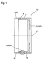
- FIG. 1 shows a rotor carrier 1, namely a two-part rotor carrier 2.
- a rotor hub 3 which is formed substantially in the shape of a pot 4, wherein the pot 4 is a rotary body 5 which is rotationally symmetrical to a rotational axis 6 of the rotor carrier 1 and a substantially parallel to the axis of rotation 6 side wall 7, on the outside 8, a support member 9 of the rotor support 1 is applied to form the two-part rotor support 2, and wherein the support member 9 is formed as a pipe section 10.
- the rotor hub 3 in this case forms one part 11 of the rotor carrier 1, while the supporting part 9 forms the other part 12 of the rotor carrier 1.
- connection point 13 is connected to the other part 12 via at least one connection point 13, which is formed as a passing through point 14.
- material 15 of the one part 11 is introduced into the other part 12, so that the other part 12 is penetrated by material 15 of the one part 11.
- connection point 13 is shown here merely as an example as a single connection point 13.
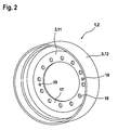
- FIG. 2 shows the rotor arm 1, namely the two-piece rotor arm 2 with the rotor hub 3 as the one part 11 and the rotatably connected to this other part 12, namely the support member 9.
- the rotor hub 3 on its bottom 17 pot mounting recesses 18, which may be combined in particular for correct alignment with Drehausrichtstoffn 19 and / or center holes.
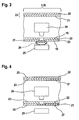
- FIG. 3 shows the method of clinching on a portion 20 of the two-part rotor support 2, namely a simplified plan illustrated side wall portion 21 of the rotor hub 3 and a tube wall portion 22 of the tubular portion 10 formed as a support member 9.
- the clinching can also be done in a different direction than shown here.
- the clinching is performed here without pre-machining the side wall portion 21 and / or the tube wall portion 22 of the full material 23 of both parts, such that a press ram 24 impinges on the full material 23 of the superimposed side wall portions 21 and tube wall portions 22, and this in a form adapted to him Die 25 is transformed into it.
- material 15 of the tube wall section 22 is introduced into material 15 of the side wall section 21, the side wall section 21 consequently penetrated by material 15 of the tube wall section 22.
- the design of the die 25 results in the formation of a projection 26 on the die side of the side wall section 21.
- FIG. 4 shows the clinching in turn on a simplified plan illustrated side wall portion 21 and a tube wall portion 22, wherein the formation of a projection 26 (FIG. FIG. 3 ) should be avoided.
- the press die 24 is in this case in correspondence of the die 25 formed such that a by pressing the full material 23 of the tube wall portion 22 by the full material 23 of the side wall portion 21 effected cantilever does not occur, but a deformation of the side wall portion 21 via a side wall portion 21 facing the die side 27 does not take place.
- the die 25 is preferably planar toward the die side 27.
- FIG. 5 shows the clinching with a side wall portion 21, which has a recess 28, for example a hole punching 29 or a bore 30 after a pre-processing.
- the pipe wall section 22 lying on it is not preprocessed, in particular not pre-punched;
- the press die 24, in cooperation with the die 25, forms a cup-shaped passage 31 of the recess 28 made in the side wall section 21, the projection 26 embracing the recess 28 on the die side and thus good strength the enforcing shank 14 formed in this way is achieved.
- FIG. 6 shows the clinching during preprocessing of both parts, namely the side wall portion 21 and the tube wall portion 22.
- the tube wall portion 22 as well as the side wall portion 21 for this purpose, the recess 28, wherein the recess 28 in the tube wall portion 22 as angled, for example, diagonally cut / countersunk Rohrwandabêtaus Principleung 32 is formed, such that the pipe wall recess on the side wall portion 21 facing away from the side has a larger diameter on the side wall portion 21 facing side.
- the recess 28 is formed in the side wall portion 21 as sowandausnaturalung 33, such that the Sowandausnaturalung 33 was prepared in the course of, for example, a combined punching / forming process and a substantially perpendicular to the plane 34 of the side wall portion 21 projection in the direction of the tube wall portion 22, namely in particular projecting into the pipe wall recess 32 wall projection 35.
- the press ram 24 has, for the further embodiment of the enforcing joint 14, a stamping mandrel 36, for example of a conical or frusto-conical shape, which in the course of the pressing process engages the wall projection 35 via the pipe wall recess 32 presses and this plastically permanently deformed, so that the Wandauskragung 35 pressed into the pipe wall recess 32 non-positively and positively, or is folded.
- a stamping mandrel 36 for example of a conical or frusto-conical shape, which in the course of the pressing process engages the wall projection 35 via the pipe wall recess 32 presses and this plastically permanently deformed, so that the Wandauskragung 35 pressed into the pipe wall recess 32 non-positively and positively, or is folded.
Landscapes
- Engineering & Computer Science (AREA)
- Power Engineering (AREA)
- Mechanical Engineering (AREA)
- Manufacturing & Machinery (AREA)
- Manufacture Of Motors, Generators (AREA)
- Iron Core Of Rotating Electric Machines (AREA)
- Insulation, Fastening Of Motor, Generator Windings (AREA)
Abstract
Description
Die Erfindung betrifft ein Verfahren zum Verbinden von Teilen eines mehrteiligen Rotorträgers einer elektrischen Maschine nach dem Oberbegriff des Anspruchs 1 und einen solchen mehrteiligen Rotorträger.The invention relates to a method for connecting parts of a multi-part rotor carrier of an electric machine according to the preamble of claim 1 and such a multi-part rotor carrier.
Bei der Fertigung von Rotoren für elektrische Maschinen sind heute einteilige, umform- oder auch gusstechnisch hergestellte Rotorträger verbreitet, die aufgrund ihrer technischen und, je nach Einsatzgebiet, möglichen wirtschaftlichen Nachteile zunehmend von mehrteiligen Rotorträgem ersetzt werden. Diese mehrteiligen Rotorträger können beispielsweise aus einer Rotornabe, die etwa in Topfform hergestellt wird, und aus einem auf diese aufgebrachten Tragteil in Form eines Zylinderrohrabschnittes bestehen, so dass Rotornabe und Tragteil separat hergestellt werden und das Tragteil beispielsweise in seiner kompletten Axialerstreckung elektrisch geschaltet werden kann, ohne dass Kurvenradien bei Übergang in die Rotornabe zu beachten sind. Ferner kann die Rotornabe innerhalb des Tragteils in weiten Grenzen axial relativ zum Tragteil verschoben beziehungsweise angeordnet werden, so dass sich erhebliche Bauraumvorteile und -freiheiten in der Ausgestaltung der Anordnung ergeben. Die Teile mehrteiliger Rotorträger, beispielsweise die Rotornabe und das Tragteil, müssen zur Ausbildung des Rotorträgers drehfest miteinander verbunden werden, also dergestalt, dass die zu verbindenden Teile keine Relativbewegung zueinander ausführen. Im Stand der Technik werden solche mehrteilige Rotorträger überwiegend geschweißt, wobei jedoch durch den Wärmeeintrag, den die Schweißung unvermeidlich mit sich bringt, in ungünstigen Fällen thermisch bedingter Verzug eines oder mehrerer der Teile auftreten und zu Genauigkeits- und/oder Unwuchtproblemen führen kann, die aufwendig nachbearbeitet werden müssen oder, unbearbeitet, zu Qualitätseinbußen führen können. Ferner sind diese Verschweißungen insgesamt relativ aufwendig.In the manufacture of rotors for electric machines today one-piece, forming or casting technology produced rotor carrier are common, which are increasingly being replaced by multi-part Rotorträgem due to their technical and, depending on the application, possible economic disadvantages. These multi-part rotor carrier can for example consist of a rotor hub, which is produced approximately in pot form, and of a support member applied to this in the form of a cylinder tube section, so that rotor hub and support member are made separately and the support member can be electrically switched, for example, in its entire axial extent, without curvature radii have to be considered at transition into the rotor hub. Furthermore, the rotor hub within the support member can be axially displaced or arranged within wide limits relative to the support member, so that there are considerable space advantages and freedom in the design of the arrangement. The parts of multi-part rotor carrier, such as the rotor hub and the support member must be rotatably connected to each other to form the rotor carrier, so in such a way that the parts to be joined perform no relative movement to each other. In the prior art, such multi-part rotor arm are welded mainly, but in heat-affected, inevitably entails the welding, occur in unfavorable cases, thermally induced distortion of one or more of the parts and can lead to accuracy and / or imbalance problems that consuming must be reworked or, unprocessed, can lead to quality losses. Furthermore, these welds are relatively expensive overall.
Aufgabe der Erfindung ist es, ein Verfahren zum Verbinden von Teilen eines mehrteiligen Rotorträgers einer elektrischen Maschine bereitzustellen, das die genannten Nachteile vermeidet, und eine kostengünstige und fertigungstechnisch optimierte Herstellung mehrteiliger Rotorträger ermöglicht.The object of the invention is to provide a method for connecting parts of a multi-part rotor carrier of an electrical machine, which avoids the disadvantages mentioned, and enables a cost-effective and production-optimized production of multi-part rotor carrier.
Diese aufgabe wird erfindungsgemäß durch das Verfahren nach Anspruch 1 gelöst. Die einzelnen Teile des mehrteiligen Rotorträgers werden in aus dem Stand der Technik geläufiger Art und Weise umform- oder gusstechnisch oder zerspanend aus Vollmaterial hergestellt. Die Teile beschränken sich hierbei auf in diesen Verfahren einfach und kostengünstig herzustellenden Teile, insbesondere bei großformatigen elektrischen Maschinen, wie sie etwa in Elektro- und Hybridantrieben Verwendung finden. Diese Teile werden in der hierfür erforderlichen Weise bearbeitet, und dann durch einen Verbindungsvorgang miteinander drehfest verbunden. Als Verbindungsvorgang erfolgt ein Durchsetzfügen, das im Stand der Technik auch als Druckfügen, Clinchen oder Toxen als bewährte Verbindungstechnik für Bleche bekannt ist. Durch das Durchsetzfügen erfolgt kein Wärmeeintrag in die zu verbindenden Teile, so dass ein thermischer Verzug der Teile verhindert wird. Weiter kann das Durchsetzfügen ohne Einbringung von Zusatzwerkstoffen erfolgen, was in wirtschaftlicher und in qualitativer Hinsicht von Vorteil ist. Je nach Genauigkeits- und Toleranzanforderungen an den Rotorträger kann im Anschluss an das Durchsetzfügen eine Weiterbearbeitung beispielsweise in Form von Spannungsarmglühen und/oder eine weitere spanende Bearbeitung auf die gewünschte Endgeometrie des Rotorträgers erfolgen. Unter Durchsetzfügen wird verstanden, dass Material des einen Teils dergestalt in Bereiche des anderen Teils eingetragen wird, insbesondere durch Pressen mit geeigneten Pressstempeln, dass eine kraft- und formschlüssige Verbindung im Fügebereich der zu verbindenden Teile besteht. Näheres zeigen die Ausführungsbeispiele.This object is achieved by the method according to claim 1. The individual parts of the multipart rotor carrier are produced in a manner known from the prior art by forming or casting technology or by machining from solid material. The parts are limited to simple and inexpensive to produce parts in this process, especially in large-sized electrical machines, such as those used in electric and hybrid drives. These parts are processed in the manner required for this, and then rotatably connected by a connection process. As a joining process is a clinching, which is known in the art as Druckfügen, clinching or Toxen as a proven connection technology for sheets. By the clinching, no heat is introduced into the parts to be joined, so that a thermal distortion of the parts is prevented. Next, the clinching can be done without introducing additional materials, which is economical and in qualitative Regard is beneficial. Depending on the accuracy and tolerance requirements for the rotor carrier, subsequent processing can be followed by further processing, for example in the form of stress relief annealing and / or further machining to the desired end geometry of the rotor carrier. By clinching is meant that material of one part in such a way in areas of the other Part is registered, in particular by pressing with suitable press dies, that a positive and positive connection in the joining region of the parts to be joined. Details show the embodiments.
In einer weiteren Verfahrensausbildung erfolgt das Durchsetzfügen im vollen Material der Teile. Die Teile werden vor dem Verbindungsvorgang demzufolge im Fügebereich nicht zum Zweck der Verbindungsherstellung bearbeitet, sondern das Durchsetzfügen führt zu einem Kraft- und Formschluss aus dem vollen Material der Teile, also insbesondere ohne Vorbohrungen, Vorstanzungen oder ähnliche zumindest eines der beiden zu verbindenden Teile vorbearbeitende Vorbehandlung. Hierbei ist vorteilhaft, dass das Durchsetzfügen als besonders kostengünstiger, wirtschaftlicher Verbindungsvorgang erfolgt, da, wie beschrieben, eine Vorbehandlung der zu verbindenden Teile im Fügebereich entfällt.In a further procedural training, the clinching takes place in the full material of the parts. The parts are therefore not processed in the joining area before the connection process for the purpose of connecting, but the clinching leads to a positive and positive fit of the full material of the parts, ie in particular without pre-drilling, pre-punching or similar at least one of the two parts to be connected pre-treatment pretreatment , It is advantageous that the clinching takes place as a particularly cost-effective, economical connection process, since, as described, eliminates a pretreatment of the parts to be joined in the joint area.
In einer anderen Verfahrensausbildung wird vor dem Durchsetzfügen mindestens eines der Teile im Fügebereich der herzustellenden Verbindungsstelle vorbearbeitet, insbesondere vorgelocht und/oder umgeformt. Insbesondere bei großformatigen Teilen oder solchen mit einer großen Materialstärke kann eine Vorbearbeitung des Fügebereiches wünschenswert sein, um unerwünscht hohe mechanische Belastungen im Fügebereich vermeiden zu können, insbesondere bei sehr großen Materialstärken, bei denen nicht mehr das volle Material mit der gewünschten Genauigkeit durchsetzgefügt werden kann. Durch die Vorbearbeitung, beispielsweise eine Vorlochung, Vorstanzung oder auch Umformung wird das Durchsetzen des Materials des einen Teils mit Material des anderen Teils erleichtert, da der den Verbindungsvorgang durchführende Pressenstempel nicht mehr mehrere Teile in voller Materialstärke umformen muss. Zum Einen reduziert sich hierbei die aufzubringende Pressenkraft, zum Anderen lässt sich gerade bei großen Materialstärken eine bessere Präzision des Verbindungsvorgangs erreichen.In another method training, at least one of the parts in the joining region of the connection point to be produced is pre-machined before the clinching, in particular pre-punched and / or reshaped. Particularly in the case of large-format parts or those with a large material thickness, pre-machining of the joining region may be desirable in order to avoid undesirably high mechanical loads in the joining region, in particular in the case of very large material thicknesses in which it is no longer possible to enforce the full material with the desired accuracy. Through the pre-processing, for example, a pre-punching, pre-punching or forming the penetration of the material of one part with material of the other part is facilitated because the connecting operation performing press ram no longer has to reshape several parts in full thickness. On the one hand, the press force to be applied is reduced, on the other hand, a better precision of the connection process can be achieved, especially with large material thicknesses.
Erfindungsgemäß ist ausserdem ein mehrteiliger Rotorträger gemäß Anspruch 4 Vorgesehen. Wie vorstehend beschrieben, wird die Durchsetzfügestelle im Wege der Kaltverformung als Materialdurchsetzung des Materials des einen Teils mit Material des anderen Teils durch Kraftbeaufschlagung mittels eines Pressenstempels hergestellt. Ein unnötiger Wärmeeintrag und insbesondere ein thermisches Verziehen der zu verbindenden Teile wird hierdurch in vorteilhafter Weise vermieden.According to the invention, a multi-part rotor carrier according to claim 4 is also provided. As described above, the clinching ridge is made by cold deformation as material passage of the material of the one part with material of the other part by applying force by means of a press ram. An unnecessary heat input and in particular a thermal distortion of the parts to be joined is thereby avoided in an advantageous manner.
In einer weiteren Ausführungsform des Rotorsträgers ist die Durchsetzfügestelle aus dem vollen Material der Teile erstellt. Insbesondere bei nicht besonders großer Materialstärke eines oder mehrerer Teile lässt sich so kostengünstig eine drehfeste Verbindung ohne großen Fertigungsaufwand herstellen.In a further embodiment of the rotor carrier, the enforcing point is made of the full material of the parts. In particular, not particularly large material thickness of one or more parts can be as cost-effective to produce a rotationally fixed connection without much manufacturing effort.
In einer anderen Ausführungsform weist das mindestens eine Teil eine Formung oder eine Umformung auf, in die durch das Durchsetzfügen Material des anderen Teils hineingedrängt ist. Hierbei lassen sich kostengünstig auch materialstarke Teile miteinander im Wege des Durchsetzfügens verbinden, ohne dass der Rotorträger durch das bislang erforderliche Verschweißen der Teile einen unerwünschten Wärmeeintrag erfährt. Durch die Formung oder Umformung lässt sich beispielsweise ein formschlüssiges Überlappen oder Überklappen von Material des einen Teils über Material des anderen Teils erreichen, so dass eine ganz besonders feste, formschlüssige Verbindung zwischen den zu verbindenden Teilen erzielt werden kann.In another embodiment, the at least one part of a shaping or forming, in which is pushed by the clinching material of the other part. In this case, high-cost parts can also be inexpensively connected to one another in the way of clinching without the rotor arm being subjected to undesired heat input due to the previously required welding of the parts. By shaping or reshaping, for example, a form-fitting overlapping or folding over of material of one part can be achieved via material of the other part, so that a very particularly firm, positive connection between the parts to be joined can be achieved.
Weitere vorteilhafte Ausführungsformen ergeben sich aus den Unteransprüchen und aus Kombinationen derselben.Further advantageous embodiments will become apparent from the dependent claims and combinations thereof.
Die Erfindung wird nachfolgend anhand von Ausführungsbeispielen näher erläutert, ohne jedoch auf diese beschränkt zu sein.The invention will be explained in more detail with reference to embodiments, but without being limited to these.
Es zeigen
- Figur 1
- einen zweiteiligen Rotorträger mit Rotornabe und hierauf angeordnetem Tragteil im Längsschnitt;
- Figur 2
- denselben Rotorträger in perspektivischer Darstellung;
- Figur 3
- das Durchsetzfügen aus dem vollen Material;
- Figur 4
- das Durchsetzfügen aus dem vollen Material ohne Auskragung;
- Figur 5
- das Durchsetzfügen mit einem vorgelochten Teil und
- Figur 6
- das Durchsetzfügen mit zwei vorgelochten Teilen, von denen eines vorher umgeformt ist.
- FIG. 1
- a two-part rotor arm with rotor hub and arranged thereon support member in longitudinal section;
- FIG. 2
- the same rotor carrier in perspective view;
- FIG. 3
- the clinching from the full material;
- FIG. 4
- the clinching from the full material without projection;
- FIG. 5
- the clinching with a pre-punched part and
- FIG. 6
- the clinching with two pre-punched parts, one of which has previously been formed.
Umgeformt wird hierbei lediglich das volle Material 23 des Rohrwandabschnittes 22, so dass dieses nach unten seitlich in das volle Material 23 des Seitenwandabschnittes 21 hineingedrückt wird, ohne dass jedoch eine Verformung des Seitenwandabschnittes 21 hin zur Matrize 25 erfolgt. Die Matrize 25 ist in diesem Fall zur Matrizenseite 27 hin bevorzugt plan ausgebildet.In this case, only the
Claims (6)
- Method for connecting parts of a multi-part rotor support of an electrical machine, with the rotor support having a rotor hub as one part and a supporting part, which is arranged on the rotor hub, as another part, with the rotor hub and the supporting part being connected to one another in a rotationally fixed manner by means of a connection process, characterized in that a clinching operation is performed as the connection process.
- Method according to Claim 1, characterized in that the clinching operation is performed with the solid material of the parts.
- Method according to either of the preceding claims, characterized in that at least one of the parts is pre-processed, in particular pre-perforated and/or shaped, in the joining region of the connection point to be produced, before the clinching operation.
- Multi-part rotor support of an electrical machine, which rotor support has a rotor hub as one part and a supporting part, which is arranged on the rotor hub, as another part, with the rotor hub and the supporting part being connected to one another in a rotationally fixed manner by means of at least one connection process, characterized in that a clinching point (14) is provided as the connection point (13).
- Rotor support according to Claim 4, characterized in that the clinching point (14) is created from the solid material (23) of the parts (11, 12).
- Rotor support according to Claims 4 and 5, characterized in that the at least one part (11) has a pre-perforated or shaped portion into which material (15) of the other part (12) is pushed by the clinching operation.
Applications Claiming Priority (2)
| Application Number | Priority Date | Filing Date | Title |
|---|---|---|---|
| DE102007049149A DE102007049149A1 (en) | 2007-10-12 | 2007-10-12 | Method for connecting parts of a multi-part rotor carrier and rotor carrier of an electric machine |
| PCT/EP2008/063020 WO2009050027A1 (en) | 2007-10-12 | 2008-09-29 | Method for connecting parts of a multiple-part rotor carrier and rotor carrier of an electric engine |
Publications (2)
| Publication Number | Publication Date |
|---|---|
| EP2210331A1 EP2210331A1 (en) | 2010-07-28 |
| EP2210331B1 true EP2210331B1 (en) | 2011-01-19 |
Family
ID=40328846
Family Applications (1)
| Application Number | Title | Priority Date | Filing Date |
|---|---|---|---|
| EP08804877A Not-in-force EP2210331B1 (en) | 2007-10-12 | 2008-09-29 | Method for connecting parts of a multiple-part rotor carrier and rotor carrier of an electric engine |
Country Status (6)
| Country | Link |
|---|---|
| US (1) | US20100213797A1 (en) |
| EP (1) | EP2210331B1 (en) |
| CN (1) | CN101821924A (en) |
| AT (1) | ATE496416T1 (en) |
| DE (2) | DE102007049149A1 (en) |
| WO (1) | WO2009050027A1 (en) |
Cited By (1)
| Publication number | Priority date | Publication date | Assignee | Title |
|---|---|---|---|---|
| DE102019108902A1 (en) * | 2019-04-04 | 2020-10-08 | Benteler Automobiltechnik Gmbh | Battery tray with clinch connection |
Families Citing this family (2)
| Publication number | Priority date | Publication date | Assignee | Title |
|---|---|---|---|---|
| DE102012008015A1 (en) * | 2012-04-24 | 2013-10-24 | Daimler Ag | Rotor carrier and method for producing a rotor carrier |
| FR3033215B1 (en) * | 2015-02-26 | 2017-02-24 | Valeo Vision | POWER SOCKET FOR VEHICLE COCKPIT |
Family Cites Families (10)
| Publication number | Priority date | Publication date | Assignee | Title |
|---|---|---|---|---|
| US4174559A (en) * | 1978-02-09 | 1979-11-20 | J.J. & M. | Fastening method |
| EP0133858B1 (en) * | 1983-08-12 | 1986-09-10 | Essa Fabrique de Machines S.A. | Method of and device for manufacturing packets made of sheet plates for magnetic cores of electric machines |
| US6343773B1 (en) * | 1999-01-21 | 2002-02-05 | Shop Vac Corporation | Support structure |
| DE19915186A1 (en) * | 1999-04-05 | 2000-11-09 | Werner Klaeui | Light and energy system for bicycles, motorcycles and multi-wheel vehicles |
| DE19939528A1 (en) * | 1999-08-20 | 2001-02-22 | Bayerische Motoren Werke Ag | Electrical machine with a rotor and a stator |
| DE10230284B4 (en) * | 2002-07-05 | 2008-10-16 | Daimler Ag | Method and device for attaching components to circumferentially closed hollow sections |
| DE10252130B4 (en) * | 2002-11-04 | 2004-11-25 | Michelin Kronprinz Werke Gmbh | Method of manufacturing a vehicle wheel |
| FR2855672B1 (en) * | 2003-05-26 | 2005-08-19 | Valeo Equip Electr Moteur | VENTILATION DEVICE, IN PARTICULAR FOR A MOTOR VEHICLE ALTERNATOR |
| WO2006001652A1 (en) * | 2004-06-24 | 2006-01-05 | Lg Electronics Inc. | Motor of washing machine |
| US7355309B2 (en) * | 2004-08-06 | 2008-04-08 | Northern Power Systems, Inc. | Permanent magnet rotor for a direct drive generator or a low speed motor |
-
2007
- 2007-10-12 DE DE102007049149A patent/DE102007049149A1/en not_active Ceased
-
2008
- 2008-09-29 AT AT08804877T patent/ATE496416T1/en active
- 2008-09-29 US US12/682,395 patent/US20100213797A1/en not_active Abandoned
- 2008-09-29 WO PCT/EP2008/063020 patent/WO2009050027A1/en active Application Filing
- 2008-09-29 DE DE502008002435T patent/DE502008002435D1/en active Active
- 2008-09-29 CN CN200880111184A patent/CN101821924A/en active Pending
- 2008-09-29 EP EP08804877A patent/EP2210331B1/en not_active Not-in-force
Cited By (1)
| Publication number | Priority date | Publication date | Assignee | Title |
|---|---|---|---|---|
| DE102019108902A1 (en) * | 2019-04-04 | 2020-10-08 | Benteler Automobiltechnik Gmbh | Battery tray with clinch connection |
Also Published As
| Publication number | Publication date |
|---|---|
| DE502008002435D1 (en) | 2011-03-03 |
| ATE496416T1 (en) | 2011-02-15 |
| CN101821924A (en) | 2010-09-01 |
| DE102007049149A1 (en) | 2009-04-16 |
| EP2210331A1 (en) | 2010-07-28 |
| US20100213797A1 (en) | 2010-08-26 |
| WO2009050027A1 (en) | 2009-04-23 |
Similar Documents
| Publication | Publication Date | Title |
|---|---|---|
| EP1198309B1 (en) | Method, device and auxiliary joining part for effecting a mechanical joining | |
| EP1886030B1 (en) | Rivet | |
| DE19861391B4 (en) | A method of forming a hub disc and spinning roller for use in forming a hub disc | |
| WO2006084609A1 (en) | Method for permanently fixing at least one component to a base component using a plastically deformed bolt | |
| EP2900414A2 (en) | Welding auxiliary joining part and method for connecting components by way of said welding auxiliary joining part | |
| EP3690260B1 (en) | Semi-hollow punch rivet, a punch rivet joint of at least two components by means of the semi-hollow punch rivet as well as a method for connecting the components with the semi-hollow punch rivet | |
| DE102011109815A1 (en) | Connection of at least two adjoining components | |
| DE102010020569A1 (en) | Thermally joining first component with second component by electrical heating, comprises provisioning joining auxiliary agent at joining position of component, and melting joining auxiliary agent and second component by electrical heating | |
| CH704438B1 (en) | A process for producing a cam for a camshaft. | |
| WO2021228493A1 (en) | Method for producing a rotor, and rotor | |
| DE102009044678B4 (en) | Method and device for producing a positive connection of different cup-shaped components of a brake drum | |
| EP2210331B1 (en) | Method for connecting parts of a multiple-part rotor carrier and rotor carrier of an electric engine | |
| EP1368153B1 (en) | Method for assembling a camshaft | |
| EP1763412B1 (en) | Flanging devce with a tilting system | |
| EP2349604B1 (en) | Method for producing a cellular wheel | |
| EP2446173B1 (en) | Welded structure, in particular planet carrier, method for producing said structure and device for carrying out the method | |
| DE102019208366B4 (en) | Adjustable roll stabilizer for a motor vehicle, housing for an adjustable roll stabilizer and method for its manufacture | |
| EP3054182A1 (en) | Method for producing a joint connection between a joint housing and a connection component and suspension component produced according to the method | |
| DE19849981C5 (en) | Method for forming a disc-shaped part with hub and spinning roller for the process | |
| EP0997210B1 (en) | Method of manufacturing of disc-shaped objects with hub and pressure roll for realising this method | |
| DE19643076C2 (en) | Device for punching and joining at least two sheet metal parts in one operation | |
| DE102008007578A1 (en) | Method for attachment of end bearing to stator laminated core for electric motor drive, involves connecting end bearing with core by electromagnetic pulse joints so that end bearing material is embedded in depressions | |
| DE102017220816A1 (en) | JOINTING DEVICE AND METHOD FOR ADDING AT LEAST ONE COMPONENT USING AN X-ZANGE | |
| DE102021125436B3 (en) | automotive hinge | |
| WO2022053443A1 (en) | Method for producing a rotor for an electric machine with axial fixing of a laminated core by friction welding, and rotor |
Legal Events
| Date | Code | Title | Description |
|---|---|---|---|
| PUAI | Public reference made under article 153(3) epc to a published international application that has entered the european phase |
Free format text: ORIGINAL CODE: 0009012 |
|
| 17P | Request for examination filed |
Effective date: 20100512 |
|
| AK | Designated contracting states |
Kind code of ref document: A1 Designated state(s): AT BE BG CH CY CZ DE DK EE ES FI FR GB GR HR HU IE IS IT LI LT LU LV MC MT NL NO PL PT RO SE SI SK TR |
|
| AX | Request for extension of the european patent |
Extension state: AL BA MK RS |
|
| GRAP | Despatch of communication of intention to grant a patent |
Free format text: ORIGINAL CODE: EPIDOSNIGR1 |
|
| DAX | Request for extension of the european patent (deleted) | ||
| GRAS | Grant fee paid |
Free format text: ORIGINAL CODE: EPIDOSNIGR3 |
|
| GRAA | (expected) grant |
Free format text: ORIGINAL CODE: 0009210 |
|
| AK | Designated contracting states |
Kind code of ref document: B1 Designated state(s): AT BE BG CH CY CZ DE DK EE ES FI FR GB GR HR HU IE IS IT LI LT LU LV MC MT NL NO PL PT RO SE SI SK TR |
|
| REG | Reference to a national code |
Ref country code: GB Ref legal event code: FG4D Free format text: NOT ENGLISH |
|
| REG | Reference to a national code |
Ref country code: CH Ref legal event code: EP |
|
| REG | Reference to a national code |
Ref country code: IE Ref legal event code: FG4D Free format text: LANGUAGE OF EP DOCUMENT: GERMAN |
|
| REF | Corresponds to: |
Ref document number: 502008002435 Country of ref document: DE Date of ref document: 20110303 Kind code of ref document: P |
|
| REG | Reference to a national code |
Ref country code: DE Ref legal event code: R096 Ref document number: 502008002435 Country of ref document: DE Effective date: 20110303 |
|
| REG | Reference to a national code |
Ref country code: NL Ref legal event code: VDEP Effective date: 20110119 |
|
| LTIE | Lt: invalidation of european patent or patent extension |
Effective date: 20110119 |
|
| PG25 | Lapsed in a contracting state [announced via postgrant information from national office to epo] |
Ref country code: LV Free format text: LAPSE BECAUSE OF FAILURE TO SUBMIT A TRANSLATION OF THE DESCRIPTION OR TO PAY THE FEE WITHIN THE PRESCRIBED TIME-LIMIT Effective date: 20110119 Ref country code: GR Free format text: LAPSE BECAUSE OF FAILURE TO SUBMIT A TRANSLATION OF THE DESCRIPTION OR TO PAY THE FEE WITHIN THE PRESCRIBED TIME-LIMIT Effective date: 20110420 Ref country code: PT Free format text: LAPSE BECAUSE OF FAILURE TO SUBMIT A TRANSLATION OF THE DESCRIPTION OR TO PAY THE FEE WITHIN THE PRESCRIBED TIME-LIMIT Effective date: 20110519 Ref country code: SE Free format text: LAPSE BECAUSE OF FAILURE TO SUBMIT A TRANSLATION OF THE DESCRIPTION OR TO PAY THE FEE WITHIN THE PRESCRIBED TIME-LIMIT Effective date: 20110119 Ref country code: ES Free format text: LAPSE BECAUSE OF FAILURE TO SUBMIT A TRANSLATION OF THE DESCRIPTION OR TO PAY THE FEE WITHIN THE PRESCRIBED TIME-LIMIT Effective date: 20110430 Ref country code: NO Free format text: LAPSE BECAUSE OF FAILURE TO SUBMIT A TRANSLATION OF THE DESCRIPTION OR TO PAY THE FEE WITHIN THE PRESCRIBED TIME-LIMIT Effective date: 20110419 Ref country code: LT Free format text: LAPSE BECAUSE OF FAILURE TO SUBMIT A TRANSLATION OF THE DESCRIPTION OR TO PAY THE FEE WITHIN THE PRESCRIBED TIME-LIMIT Effective date: 20110119 Ref country code: HR Free format text: LAPSE BECAUSE OF FAILURE TO SUBMIT A TRANSLATION OF THE DESCRIPTION OR TO PAY THE FEE WITHIN THE PRESCRIBED TIME-LIMIT Effective date: 20110119 Ref country code: IS Free format text: LAPSE BECAUSE OF FAILURE TO SUBMIT A TRANSLATION OF THE DESCRIPTION OR TO PAY THE FEE WITHIN THE PRESCRIBED TIME-LIMIT Effective date: 20110519 |
|
| REG | Reference to a national code |
Ref country code: IE Ref legal event code: FD4D |
|
| PG25 | Lapsed in a contracting state [announced via postgrant information from national office to epo] |
Ref country code: SI Free format text: LAPSE BECAUSE OF FAILURE TO SUBMIT A TRANSLATION OF THE DESCRIPTION OR TO PAY THE FEE WITHIN THE PRESCRIBED TIME-LIMIT Effective date: 20110119 Ref country code: FI Free format text: LAPSE BECAUSE OF FAILURE TO SUBMIT A TRANSLATION OF THE DESCRIPTION OR TO PAY THE FEE WITHIN THE PRESCRIBED TIME-LIMIT Effective date: 20110119 Ref country code: NL Free format text: LAPSE BECAUSE OF FAILURE TO SUBMIT A TRANSLATION OF THE DESCRIPTION OR TO PAY THE FEE WITHIN THE PRESCRIBED TIME-LIMIT Effective date: 20110119 Ref country code: BG Free format text: LAPSE BECAUSE OF FAILURE TO SUBMIT A TRANSLATION OF THE DESCRIPTION OR TO PAY THE FEE WITHIN THE PRESCRIBED TIME-LIMIT Effective date: 20110419 Ref country code: PL Free format text: LAPSE BECAUSE OF FAILURE TO SUBMIT A TRANSLATION OF THE DESCRIPTION OR TO PAY THE FEE WITHIN THE PRESCRIBED TIME-LIMIT Effective date: 20110119 Ref country code: CY Free format text: LAPSE BECAUSE OF FAILURE TO SUBMIT A TRANSLATION OF THE DESCRIPTION OR TO PAY THE FEE WITHIN THE PRESCRIBED TIME-LIMIT Effective date: 20110119 |
|
| PG25 | Lapsed in a contracting state [announced via postgrant information from national office to epo] |
Ref country code: DK Free format text: LAPSE BECAUSE OF FAILURE TO SUBMIT A TRANSLATION OF THE DESCRIPTION OR TO PAY THE FEE WITHIN THE PRESCRIBED TIME-LIMIT Effective date: 20110119 Ref country code: IE Free format text: LAPSE BECAUSE OF FAILURE TO SUBMIT A TRANSLATION OF THE DESCRIPTION OR TO PAY THE FEE WITHIN THE PRESCRIBED TIME-LIMIT Effective date: 20110119 Ref country code: EE Free format text: LAPSE BECAUSE OF FAILURE TO SUBMIT A TRANSLATION OF THE DESCRIPTION OR TO PAY THE FEE WITHIN THE PRESCRIBED TIME-LIMIT Effective date: 20110119 |
|
| PLBE | No opposition filed within time limit |
Free format text: ORIGINAL CODE: 0009261 |
|
| STAA | Information on the status of an ep patent application or granted ep patent |
Free format text: STATUS: NO OPPOSITION FILED WITHIN TIME LIMIT |
|
| PG25 | Lapsed in a contracting state [announced via postgrant information from national office to epo] |
Ref country code: SK Free format text: LAPSE BECAUSE OF FAILURE TO SUBMIT A TRANSLATION OF THE DESCRIPTION OR TO PAY THE FEE WITHIN THE PRESCRIBED TIME-LIMIT Effective date: 20110119 Ref country code: RO Free format text: LAPSE BECAUSE OF FAILURE TO SUBMIT A TRANSLATION OF THE DESCRIPTION OR TO PAY THE FEE WITHIN THE PRESCRIBED TIME-LIMIT Effective date: 20110119 Ref country code: CZ Free format text: LAPSE BECAUSE OF FAILURE TO SUBMIT A TRANSLATION OF THE DESCRIPTION OR TO PAY THE FEE WITHIN THE PRESCRIBED TIME-LIMIT Effective date: 20110119 |
|
| 26N | No opposition filed |
Effective date: 20111020 |
|
| REG | Reference to a national code |
Ref country code: DE Ref legal event code: R097 Ref document number: 502008002435 Country of ref document: DE Effective date: 20111020 |
|
| BERE | Be: lapsed |
Owner name: ROBERT BOSCH G.M.B.H. Effective date: 20110930 |
|
| PG25 | Lapsed in a contracting state [announced via postgrant information from national office to epo] |
Ref country code: MC Free format text: LAPSE BECAUSE OF NON-PAYMENT OF DUE FEES Effective date: 20110930 |
|
| PG25 | Lapsed in a contracting state [announced via postgrant information from national office to epo] |
Ref country code: BE Free format text: LAPSE BECAUSE OF NON-PAYMENT OF DUE FEES Effective date: 20110930 |
|
| PG25 | Lapsed in a contracting state [announced via postgrant information from national office to epo] |
Ref country code: MT Free format text: LAPSE BECAUSE OF FAILURE TO SUBMIT A TRANSLATION OF THE DESCRIPTION OR TO PAY THE FEE WITHIN THE PRESCRIBED TIME-LIMIT Effective date: 20110119 |
|
| REG | Reference to a national code |
Ref country code: CH Ref legal event code: PL |
|
| PG25 | Lapsed in a contracting state [announced via postgrant information from national office to epo] |
Ref country code: LU Free format text: LAPSE BECAUSE OF NON-PAYMENT OF DUE FEES Effective date: 20110929 |
|
| PG25 | Lapsed in a contracting state [announced via postgrant information from national office to epo] |
Ref country code: LI Free format text: LAPSE BECAUSE OF NON-PAYMENT OF DUE FEES Effective date: 20120930 Ref country code: CH Free format text: LAPSE BECAUSE OF NON-PAYMENT OF DUE FEES Effective date: 20120930 |
|
| PG25 | Lapsed in a contracting state [announced via postgrant information from national office to epo] |
Ref country code: TR Free format text: LAPSE BECAUSE OF FAILURE TO SUBMIT A TRANSLATION OF THE DESCRIPTION OR TO PAY THE FEE WITHIN THE PRESCRIBED TIME-LIMIT Effective date: 20110119 |
|
| PG25 | Lapsed in a contracting state [announced via postgrant information from national office to epo] |
Ref country code: HU Free format text: LAPSE BECAUSE OF FAILURE TO SUBMIT A TRANSLATION OF THE DESCRIPTION OR TO PAY THE FEE WITHIN THE PRESCRIBED TIME-LIMIT Effective date: 20110119 |
|
| REG | Reference to a national code |
Ref country code: AT Ref legal event code: MM01 Ref document number: 496416 Country of ref document: AT Kind code of ref document: T Effective date: 20130929 |
|
| PG25 | Lapsed in a contracting state [announced via postgrant information from national office to epo] |
Ref country code: AT Free format text: LAPSE BECAUSE OF NON-PAYMENT OF DUE FEES Effective date: 20130929 |
|
| REG | Reference to a national code |
Ref country code: FR Ref legal event code: PLFP Year of fee payment: 9 |
|
| REG | Reference to a national code |
Ref country code: FR Ref legal event code: PLFP Year of fee payment: 10 |
|
| REG | Reference to a national code |
Ref country code: FR Ref legal event code: PLFP Year of fee payment: 11 |
|
| PGFP | Annual fee paid to national office [announced via postgrant information from national office to epo] |
Ref country code: DE Payment date: 20191125 Year of fee payment: 12 |
|
| PGFP | Annual fee paid to national office [announced via postgrant information from national office to epo] |
Ref country code: GB Payment date: 20200923 Year of fee payment: 13 Ref country code: FR Payment date: 20200921 Year of fee payment: 13 |
|
| PGFP | Annual fee paid to national office [announced via postgrant information from national office to epo] |
Ref country code: IT Payment date: 20200930 Year of fee payment: 13 |
|
| REG | Reference to a national code |
Ref country code: DE Ref legal event code: R119 Ref document number: 502008002435 Country of ref document: DE |
|
| PG25 | Lapsed in a contracting state [announced via postgrant information from national office to epo] |
Ref country code: DE Free format text: LAPSE BECAUSE OF NON-PAYMENT OF DUE FEES Effective date: 20210401 |
|
| GBPC | Gb: european patent ceased through non-payment of renewal fee |
Effective date: 20210929 |
|
| PG25 | Lapsed in a contracting state [announced via postgrant information from national office to epo] |
Ref country code: GB Free format text: LAPSE BECAUSE OF NON-PAYMENT OF DUE FEES Effective date: 20210929 Ref country code: FR Free format text: LAPSE BECAUSE OF NON-PAYMENT OF DUE FEES Effective date: 20210930 |
|
| PG25 | Lapsed in a contracting state [announced via postgrant information from national office to epo] |
Ref country code: IT Free format text: LAPSE BECAUSE OF NON-PAYMENT OF DUE FEES Effective date: 20210929 |