EP2209177A2 - Multi-Mode charging system for an electric vehicle - Google Patents
Multi-Mode charging system for an electric vehicle Download PDFInfo
- Publication number
- EP2209177A2 EP2209177A2 EP09014408A EP09014408A EP2209177A2 EP 2209177 A2 EP2209177 A2 EP 2209177A2 EP 09014408 A EP09014408 A EP 09014408A EP 09014408 A EP09014408 A EP 09014408A EP 2209177 A2 EP2209177 A2 EP 2209177A2
- Authority
- EP
- European Patent Office
- Prior art keywords
- mode
- charging
- battery
- electric vehicle
- battery pack
- Prior art date
- Legal status (The legal status is an assumption and is not a legal conclusion. Google has not performed a legal analysis and makes no representation as to the accuracy of the status listed.)
- Granted
Links
Images


Classifications
-
- B—PERFORMING OPERATIONS; TRANSPORTING
- B60—VEHICLES IN GENERAL
- B60L—PROPULSION OF ELECTRICALLY-PROPELLED VEHICLES; SUPPLYING ELECTRIC POWER FOR AUXILIARY EQUIPMENT OF ELECTRICALLY-PROPELLED VEHICLES; ELECTRODYNAMIC BRAKE SYSTEMS FOR VEHICLES IN GENERAL; MAGNETIC SUSPENSION OR LEVITATION FOR VEHICLES; MONITORING OPERATING VARIABLES OF ELECTRICALLY-PROPELLED VEHICLES; ELECTRIC SAFETY DEVICES FOR ELECTRICALLY-PROPELLED VEHICLES
- B60L8/00—Electric propulsion with power supply from forces of nature, e.g. sun or wind
- B60L8/003—Converting light into electric energy, e.g. by using photo-voltaic systems
-
- B—PERFORMING OPERATIONS; TRANSPORTING
- B60—VEHICLES IN GENERAL
- B60L—PROPULSION OF ELECTRICALLY-PROPELLED VEHICLES; SUPPLYING ELECTRIC POWER FOR AUXILIARY EQUIPMENT OF ELECTRICALLY-PROPELLED VEHICLES; ELECTRODYNAMIC BRAKE SYSTEMS FOR VEHICLES IN GENERAL; MAGNETIC SUSPENSION OR LEVITATION FOR VEHICLES; MONITORING OPERATING VARIABLES OF ELECTRICALLY-PROPELLED VEHICLES; ELECTRIC SAFETY DEVICES FOR ELECTRICALLY-PROPELLED VEHICLES
- B60L58/00—Methods or circuit arrangements for monitoring or controlling batteries or fuel cells, specially adapted for electric vehicles
- B60L58/10—Methods or circuit arrangements for monitoring or controlling batteries or fuel cells, specially adapted for electric vehicles for monitoring or controlling batteries
- B60L58/12—Methods or circuit arrangements for monitoring or controlling batteries or fuel cells, specially adapted for electric vehicles for monitoring or controlling batteries responding to state of charge [SoC]
- B60L58/15—Preventing overcharging
-
- B—PERFORMING OPERATIONS; TRANSPORTING
- B60—VEHICLES IN GENERAL
- B60L—PROPULSION OF ELECTRICALLY-PROPELLED VEHICLES; SUPPLYING ELECTRIC POWER FOR AUXILIARY EQUIPMENT OF ELECTRICALLY-PROPELLED VEHICLES; ELECTRODYNAMIC BRAKE SYSTEMS FOR VEHICLES IN GENERAL; MAGNETIC SUSPENSION OR LEVITATION FOR VEHICLES; MONITORING OPERATING VARIABLES OF ELECTRICALLY-PROPELLED VEHICLES; ELECTRIC SAFETY DEVICES FOR ELECTRICALLY-PROPELLED VEHICLES
- B60L58/00—Methods or circuit arrangements for monitoring or controlling batteries or fuel cells, specially adapted for electric vehicles
- B60L58/10—Methods or circuit arrangements for monitoring or controlling batteries or fuel cells, specially adapted for electric vehicles for monitoring or controlling batteries
- B60L58/24—Methods or circuit arrangements for monitoring or controlling batteries or fuel cells, specially adapted for electric vehicles for monitoring or controlling batteries for controlling the temperature of batteries
- B60L58/26—Methods or circuit arrangements for monitoring or controlling batteries or fuel cells, specially adapted for electric vehicles for monitoring or controlling batteries for controlling the temperature of batteries by cooling
-
- B—PERFORMING OPERATIONS; TRANSPORTING
- B60—VEHICLES IN GENERAL
- B60L—PROPULSION OF ELECTRICALLY-PROPELLED VEHICLES; SUPPLYING ELECTRIC POWER FOR AUXILIARY EQUIPMENT OF ELECTRICALLY-PROPELLED VEHICLES; ELECTRODYNAMIC BRAKE SYSTEMS FOR VEHICLES IN GENERAL; MAGNETIC SUSPENSION OR LEVITATION FOR VEHICLES; MONITORING OPERATING VARIABLES OF ELECTRICALLY-PROPELLED VEHICLES; ELECTRIC SAFETY DEVICES FOR ELECTRICALLY-PROPELLED VEHICLES
- B60L58/00—Methods or circuit arrangements for monitoring or controlling batteries or fuel cells, specially adapted for electric vehicles
- B60L58/10—Methods or circuit arrangements for monitoring or controlling batteries or fuel cells, specially adapted for electric vehicles for monitoring or controlling batteries
- B60L58/24—Methods or circuit arrangements for monitoring or controlling batteries or fuel cells, specially adapted for electric vehicles for monitoring or controlling batteries for controlling the temperature of batteries
- B60L58/27—Methods or circuit arrangements for monitoring or controlling batteries or fuel cells, specially adapted for electric vehicles for monitoring or controlling batteries for controlling the temperature of batteries by heating
-
- H—ELECTRICITY
- H02—GENERATION; CONVERSION OR DISTRIBUTION OF ELECTRIC POWER
- H02J—ELECTRIC POWER NETWORKS; CIRCUIT ARRANGEMENTS OR SYSTEMS FOR SUPPLYING OR DISTRIBUTING ELECTRIC POWER; SYSTEMS FOR STORING ELECTRIC ENERGY
- H02J7/00—Circuit arrangements for charging or discharging batteries or for supplying loads from batteries
- H02J7/90—Regulation of charging or discharging current or voltage
- H02J7/971—Regulation of charging or discharging current or voltage the charge cycle being controlled or terminated in response to non-electric parameters
- H02J7/975—Regulation of charging or discharging current or voltage the charge cycle being controlled or terminated in response to non-electric parameters in response to temperature
- H02J7/977—Regulation of charging or discharging current or voltage the charge cycle being controlled or terminated in response to non-electric parameters in response to temperature of the battery
-
- B—PERFORMING OPERATIONS; TRANSPORTING
- B60—VEHICLES IN GENERAL
- B60L—PROPULSION OF ELECTRICALLY-PROPELLED VEHICLES; SUPPLYING ELECTRIC POWER FOR AUXILIARY EQUIPMENT OF ELECTRICALLY-PROPELLED VEHICLES; ELECTRODYNAMIC BRAKE SYSTEMS FOR VEHICLES IN GENERAL; MAGNETIC SUSPENSION OR LEVITATION FOR VEHICLES; MONITORING OPERATING VARIABLES OF ELECTRICALLY-PROPELLED VEHICLES; ELECTRIC SAFETY DEVICES FOR ELECTRICALLY-PROPELLED VEHICLES
- B60L2250/00—Driver interactions
- B60L2250/16—Driver interactions by display
-
- Y—GENERAL TAGGING OF NEW TECHNOLOGICAL DEVELOPMENTS; GENERAL TAGGING OF CROSS-SECTIONAL TECHNOLOGIES SPANNING OVER SEVERAL SECTIONS OF THE IPC; TECHNICAL SUBJECTS COVERED BY FORMER USPC CROSS-REFERENCE ART COLLECTIONS [XRACs] AND DIGESTS
- Y02—TECHNOLOGIES OR APPLICATIONS FOR MITIGATION OR ADAPTATION AGAINST CLIMATE CHANGE
- Y02T—CLIMATE CHANGE MITIGATION TECHNOLOGIES RELATED TO TRANSPORTATION
- Y02T10/00—Road transport of goods or passengers
- Y02T10/60—Other road transportation technologies with climate change mitigation effect
- Y02T10/70—Energy storage systems for electromobility, e.g. batteries
-
- Y—GENERAL TAGGING OF NEW TECHNOLOGICAL DEVELOPMENTS; GENERAL TAGGING OF CROSS-SECTIONAL TECHNOLOGIES SPANNING OVER SEVERAL SECTIONS OF THE IPC; TECHNICAL SUBJECTS COVERED BY FORMER USPC CROSS-REFERENCE ART COLLECTIONS [XRACs] AND DIGESTS
- Y02—TECHNOLOGIES OR APPLICATIONS FOR MITIGATION OR ADAPTATION AGAINST CLIMATE CHANGE
- Y02T—CLIMATE CHANGE MITIGATION TECHNOLOGIES RELATED TO TRANSPORTATION
- Y02T10/00—Road transport of goods or passengers
- Y02T10/60—Other road transportation technologies with climate change mitigation effect
- Y02T10/7072—Electromobility specific charging systems or methods for batteries, ultracapacitors, supercapacitors or double-layer capacitors
Definitions
- the present invention relates generally to batteries and, more particularly, to a method and apparatus for providing different charging and cooling modes for the battery pack of an electric vehicle.
- Batteries have been used for decades to supply power to a variety of different electrical and electro-mechanical devices. Early batteries, referred to as disposable batteries, were simply used until depleted and then discarded and replaced with one or more new batteries. A newer type of battery, referred to as a rechargeable battery, is capable of being recharged and then reused, therefore offering economic, environmental and ease-of-use benefits compared to a disposable battery.
- rechargeable batteries provide a much longer service life than disposable batteries, their service life is not unlimited.
- a rechargeable battery can typically be recharged anywhere from 100 times (e.g., alkaline) to 1000 times (e.g., lithium-ion, lithium-polymer) to 20,000 times or more (e.g., thin film lithium).
- the number of cycles that a rechargeable battery can be recharged depends on a variety of other factors that include; (i) the rate of charging (i.e., slow trickle charge versus fast charge), (ii) the level of charging (i.e., 75% of full charge, full charge, over-charged, etc.), (iii) the level of discharge prior to charging (i.e., completely depleted, still charged to a low level, etc.), (iv) the storage temperature of the battery during non-use, and (v) the temperature of the battery during use.
- the rate of charging i.e., slow trickle charge versus fast charge
- the level of charging i.e., 75% of full charge, full charge, over-charged, etc.
- the level of discharge prior to charging i.e., completely depleted, still charged to a low level, etc.
- the storage temperature of the battery during non-use iv
- the temperature of the battery during use iv
- a laptop may provide two different video screen brightness levels; high brightness when the computer is plugged in, and low brightness when the computer is operating on battery power.
- a growing application for rechargeable batteries is that of electric vehicles. All-electric and hybrid vehicles, however, present a number of engineering challenges, primarily due to the need for the rechargeable battery pack of such a vehicle to meet the consumers' expectations relative to performance, range, reliability, lifetime and cost.
- the present invention provides a battery pack recharging system and user interface that helps achieve these goals.
- the present invention provides a method and apparatus that allows the end user to optimize the performance of an all-electric or hybrid vehicle, the vehicle including a battery charging system and a battery cooling system, wherein the preferred mode of operation is selected from a plurality of charging/operational modes using a selecting means, and wherein selection of a preferred mode of operation causes the charging system to utilize a specific cut-off voltage and the battery cooling system to maintain the battery pack within a specific temperature range.
- an electric vehicle multi-mode charging and operating system is comprised of a battery charging system that utilizes a cut-off voltage selected from at least three cut-off voltages; a battery cooling system for maintaining the electric vehicle's battery pack within a first preset temperature range when the battery charging system is coupled to an external charging power source, wherein the first preset temperature range is selected from at least a first temperature range and a second temperature range; and user accessible means for selecting a preferred mode from a plurality of charging/operational modes. Selection of a first mode from the plurality of charging/operational modes results in the battery charging system utilizing a first cut-off voltage and the battery cooling system maintaining the battery pack within the first temperature range when the battery charging system is coupled to an external charging power source.
- Selection of a second mode from the plurality of charging/operational modes results in the battery charging system utilizing a second cut-off voltage and the battery cooling system maintaining the battery pack within the first temperature range when the battery charging system is coupled to an external charging power source.
- Selection of a third mode from the plurality of charging/operational modes results in the battery charging system utilizing a third cut-off voltage and the battery cooling system maintaining the battery pack within the second temperature range when the battery charging system is coupled to an external charging power source.
- the first preset temperature range may further comprise a third temperature range, wherein selection of a fourth mode from the plurality of charging/operational modes results in the battery charging system utilizing the third cut-off voltage and the battery cooling system maintaining the battery pack within the third temperature range when the battery charging system is coupled to an external charging power source.
- the battery cooling system may maintain the battery pack within a second preset temperature range when the battery charging system is not coupled to an external charging power source, wherein the second preset temperature range is selected from at least a third temperature range and a fourth temperature range. Selection of the first mode from the plurality of charging/operational modes results in the battery cooling system maintaining the battery pack within the third temperature range when the battery charging system is not coupled to an external charging power source. Selection of the third mode from the plurality of charging/operational modes results in the battery cooling system maintaining the battery pack within the fourth temperature range when the battery charging system is not coupled to an external charging power source.
- the electric vehicle multi-mode battery charging and operating system may further comprise a battery heating system for preventing a battery pack temperature from falling below a preset temperature threshold when the battery charging system is not coupled to an external charging power source and when the third mode is selected.
- the electric vehicle multi-mode battery charging and operating system may further comprise a battery heating system for preventing a battery pack temperature from falling below a preset temperature threshold when the battery charging system is coupled to an external charging power source and when the fourth mode is selected.
- the selecting means of the electric vehicle multi-mode battery charging and operating system may utilize a touch-sensitive screen, a display system, a plurality of switching means (e.g., push-buttons, toggle switches, rotating switches and slide switches), a voice recognition system, or a remote mode selector.
- the system may further include at least one mode indicator.
- the system may further include means for switching between the preferred mode and a default mode.
- the system may further include user accessible means for selecting the default mode from the plurality of charging/operational modes.
- a method of setting a charging/operational mode of an electric vehicle comprising the steps of displaying a plurality of user accessible charging/operational modes, selecting a preferred mode from the plurality of user accessible charging/operational modes, displaying an indicator of the selected mode, adjusting a cut-off voltage and maintaining the temperature of the battery pack within a range of temperatures when the electric vehicle is plugged into an external charging power source, wherein the cut-off voltage and the temperature range are based on the selected mode.
- the method may further comprise the step of maintaining the temperature of the battery pack within a range of temperatures when the electric vehicle is not plugged into an external charging power source, wherein the temperature range is based on the selected mode.
- the method may further comprise the step of reverting to a default charging/operational mode from the preferred charging/operational mode after a preset period of time, or after the electric vehicle has cycled from an operational mode to a standby mode.
- battery may be used interchangeably and may refer to any of a variety of different rechargeable cell chemistries and configurations including, but not limited to, lithium ion (e.g., lithium iron phosphate, lithium cobalt oxide, other lithium metal oxides, etc.), lithium ion polymer, nickel metal hydride, nickel cadmium, nickel hydrogen, nickel zinc, silver zinc, or other battery type/configuration.
- battery pack refers to multiple individual batteries contained within a single piece or multi-piece housing, the individual batteries electrically interconnected to achieve the desired voltage and capacity for a particular application.
- electric vehicle refers to either an all electric vehicle, also referred to as an EV, plug-in hybrid vehicles, also referred to as a PHEV, or a hybrid vehicle (HEV), a hybrid vehicle utilizing multiple propulsion sources one of which is an electric drive system.
- EV all electric vehicle
- plug-in hybrid vehicles also referred to as a PHEV
- HEV hybrid vehicle
- Figs. 1-3 illustrate several battery characteristics for an exemplary battery pack. It should be understood that different battery packs, for example those using a different cell chemistry, will exhibit different profiles than those shown in Figs. 1-3 , and that these figures are only meant to be illustrative, not limiting.
- Fig. 1 is a graph that illustrates the effects of charging cut-off voltage on battery life, the cut-off voltage being the voltage at which charging is terminated.
- the cut-off voltage being the voltage at which charging is terminated.
- Curve 101 a cut-off voltage of 4.15 volts
- Curve 103 a cut-off voltage of 4.10 volts
- the capacity of the battery using the lower cut-off voltage is greater than that of the battery using the higher cut-off voltage, illustrating that the useful lifetime of a battery pack can be dramatically extended by simply lowering cut-off voltage.
- Unfortunately lowering the cut-off voltage has consequences to other aspects of the battery pack's performance, in particular capacity, since a battery charged to a higher voltage exhibits a greater capacity than the same battery charged to a lower voltage.
- Fig. 2 is a graph illustrating the effects of temperature on the cell voltage and discharge capacity of an exemplary battery.
- curve 201 corresponds to a temperature of 40° C
- curve 202 corresponds to a temperature of 30° C
- curve 203 corresponds to a temperature of 20° C.
- an increase in operating temperature from 20° C to 40° C dramatically improves discharge capacity which, in turn, can lead to both improved vehicle performance (e.g., faster acceleration) and improved driving range for an electric vehicle using such a battery pack.
- a drawback, however, of operating at a higher temperature is the effect such a temperature has on battery life, specifically shortening the battery's life.
- a battery will typically exhibit higher non-recoverable capacity loss as the temperature is increased.
- This battery characteristic is illustrated in Fig. 3 in which curve 301 is for a battery pack cycled at 35° C and curve 303 is for a battery pack cycled at 55° C. As shown, by decreasing the storage temperature of a battery, it is able to retain a much higher capacity over a longer cycle life.
- Fig. 4 is a high-level view of the primary vehicle subsystems impacted by a battery charging system designed in accordance with a preferred embodiment of the invention. It will be appreciated that a vehicle can utilize other subsystem configurations while still retaining the multi-charging mode capabilities of the present invention.
- system 400 includes a power control subsystem 401, a battery pack 403, a battery cooling subsystem 405, a battery heating subsystem 407, and a user interface 409.
- battery cooling system 405 and battery heating system 407 are combined into a temperature management system 408.
- Power control subsystem 401 is comprised of a charging module 411 that controls and monitors cut-off voltage during charging. Charging module 411 may also control and monitor the charging rate. Preferably, and as described in further detail below, power control subsystem 401 also monitors the temperature of battery pack 403 and controls that temperature using battery cooling subsystem 405. In at least one embodiment, a battery heating subsystem 407 is also used by power control subsystem 401 to achieve the desired battery pack operating and/or storage temperature.
- An exemplary battery temperature control system is described in detail in co-pending U.S. Patent Application Serial No. 11/786,108, filed April 11, 2007 , the disclosure of which is incorporated herein for any and all purposes.
- Power control subsystem 401 also monitors the state of charge for battery pack 403, for example via charging module 411.
- subsystem 401 is also capable of monitoring the rate of discharge of battery pack 403, both during vehicle operation and vehicle storage.
- subsystem 401 monitors and stores in on-board memory the number of charging cycles to which the battery has been subjected. Preferably for each charging cycle the cut-off voltage and other charging parameters are monitored and stored in memory, thereby providing information that can be used to gauge the relative health of battery pack 403 and its expected lifetime.
- charging module 411 is preferably integrated within power control subsystem 401 as shown, in at least one alternate embodiment charging module 411 is external to both the power control subsystem 401 and the vehicle.
- the portion of the charging module that converts external power to a power level (e.g., voltage) that is compatible with battery pack 403 is external to the vehicle while a second portion of the charging module that controls charging characteristics such as cut-off voltage, charging rate, etc. is internal to the vehicle.
- the entire charging module can be external to the power control subsystem 401 and the vehicle.
- battery pack 403 is configured to be plugged into, or otherwise connected to, an external power source 413 via charging module 411.
- a municipal power grid is one example of an external power source 413.
- Charging module 411 insures that the power from source 413 is converted to a form of power storable by battery pack 403.
- charging module 411 typically includes an AC to DC rectifier in order to convert power from the power source to that required by battery pack 403.
- battery pack 403 is charged in whole or in part by a power generator 415 that is contained within the vehicle, i.e., an on-board power generator, which is coupled to the battery pack via charging module 411.
- on-board power generator 415 is not necessary to the implementation of the invention, it is shown in phantom. It will be appreciated that in some embodiments, while external power source 413 is preferred for providing a full charge to battery pack 403, internal power source 415 can be used to augment the charge within the battery pack, for example by charging battery pack 403 during vehicle use, thereby extending driving range. In at least one embodiment, internal power source 415 is a regenerative braking system.
- Power control subsystem 401 also controls the power coupled from battery pack 403 to vehicle propulsion motor 417, for example using a power electronics module (PEM) 419.
- Power electronics module 419 is used to insure that the power delivered to motor 417 has the desired voltage, current, waveform, etc.
- power electronics module 419 preferably includes a DC to AC inverter, as well as the necessary control circuitry/processor to implement the various selectable charge modes as described in detail below.
- vehicle propulsion motor 417 can be comprised of a single electric motor, or multiple electric motors.
- User interface 409 is preferably integrated into the vehicle's user interface, although interface 409 can be implemented in other ways as described in detail below.
- Interface 409 provides a means for the user to control the selection of the charging mode as well as associated parameters.
- interface 409 also provides means for identifying which mode the vehicle is in at any given time, as described further below.
- the system of the present invention allows the user to select the operational mode of a vehicle, more specifically aspects of the charging, battery and power control systems that affect the performance of an electric vehicle (i.e., all electric or hybrid) and the battery pack, as well as the life expectancy of the battery pack. Preferred modes of operation will now be described in detail.
- Standard Mode - In the Standard Mode the system is configured to provide the optimal compromise between performance, driving range and battery life.
- the Standard Mode will limit the cut-off voltage during charging to approximately 70%-95% of the rated capacity.
- the cut-off voltage in the Standard Mode is set to approximately 4.10 volts.
- the Standard Mode is intended to maintain the battery pack at a relatively cool temperature during both vehicle operation (i.e., driving) and when plugged in, preferably cooling the battery pack to a temperature within the range of approximately 30° C to 35° C during vehicle operation, and within the range of approximately 20° C to 25° C when the vehicle is plugged in to the external power source.
- the Storage Mode is configured to optimize battery life when the vehicle is stored for an extended period of time, for example, for a period of time greater than 2 or 3 weeks.
- the cut-off voltage during charging is limited to approximately 30%-70%, and more preferably to approximately 30%-50%.
- the cut-off voltage in the Storage Mode is set to approximately 3.80 volts.
- the battery pack temperature is maintained at a relatively cool temperature, preferably in the range of approximately 20° C to 25° C, when the charging system is coupled to an external power source.
- the system actively lowers the charge state to the preset value, thereby helping to prolong battery life.
- a preset value e.g. 50%
- the system actively lowers the charge state by subjecting the battery pack to a load (e.g., turning on a light(s), fan, dummy load, etc.).
- Extended Driving Range Mode - This mode, also referred to as the Max Range Mode, optimizes the system for maximum driving range, i.e., distance.
- the battery is kept relatively warm, thereby decreasing battery impedance and achieving greater discharge capacity.
- the temperature is not cooled until the temperature rises to about 40° C.
- the cooling system then operates to keep it within the range of approximately 37° C to 40° C.
- the Max Range Mode is selected and the vehicle is plugged into an external power source, the battery pack is cooled to a lower temperature than normal, preferably in the range of approximately 15° C to 17° C.
- the maximum cut-off voltage is used, i.e., approximately 90% - 100% of rated capacity. In the preferred embodiment, the cut-off voltage is set to approximately 4.15 - 4.18 volts.
- Performance Mode - This mode is intended to achieve the best vehicle performance available, at the cost of both battery life and range.
- the Performance Mode uses the maximum cut-off voltage during charging, i.e., approximately 90% - 100%.
- the maximum cut-off voltage is set to approximately 4.15 to 4.18 volts.
- the battery pack temperature is allowed to rise to a temperature within the range of approximately 37° C to 40° C and then cooled to maintain the temperature within this range.
- the battery temperature is cooled (if necessary) to a temperature within the range of approximately 35° C to 40° C.
- the battery preheater is enabled when the battery temperature falls below 33° C, and is then disabled once a temperature of 35° C is reached.
- the power control subsystem via the power electronics module provides an additional performance boost.
- the system provides a temporary increase in the available current that can be supplied to motor 417.
- the available current is increased from 850 amps rms to 900 amps rms.
- the current boost is of very limited duration.
- the current boost is only allowed for a maximum duration of 5 seconds.
- the current boost can also be limited to a predetermined number of times per time period, the time period being measured in days, weeks or months.
- cut-off voltages as well as the optimal temperature ranges provided above relative to the described charging/operational modes of operation are based on a specific vehicle and battery pack.
- charging is re-initiated so that the battery is not used to power cooling subsystem 405. Charging re-initiation can start before, after, or at the same time as cooling subsystem initiation.
- the selection of a specific charging/operational mode also impacts the charging profile employed while operating the vehicle.
- This embodiment requires some form of an internal power generator 415.
- internal power generator 415 utilizes a regenerative braking system, either alone or in combination with other power generation means (e.g., roof-mounted solar panels, etc.).
- the state of charge of battery pack 403 is monitored and maintained within a predefined range using the charging capabilities provided by the internal power generator.
- the Standard Mode an average charge of approximately 50% is maintained; in the Storage Mode an average charge of 30-50% is maintained; and in the Max Range and the Performance Modes an average charge of approximately 70% is maintained.
- the power control subsystem 401 determines the voltage and current of the source. If the voltage is less than a preset value, e.g., 150 volts, or if the line current is less than or equal to a preset value, e.g., 12 amps, battery cooling is limited. This approach can be used, for example, to shorten charge time. In a specific application, when subsystem 401 determines that the voltage/current of the external power source is less than the preset value, the battery temperature is cooled to a temperature within the range of approximately 37° C to 40° C regardless of the charging/operational mode selected, and once the battery pack temperature is less than 37° C, the cooling subsystem is disabled.
- a preset value e.g. 150 volts
- a preset value e.g. 12 amps
- the system of the present invention allows the user to select a mode based on one or more battery/power system characteristics.
- means e.g., dial, menu based system on a visual display, buttons, etc.
- the user is given four or more options such as 3.8 volts, 3.9 volts, 4.0 volts, 4.1 volts and 4.15 volts.
- the provided means allow the user to select the average charge, e.g., 30%, 40%, 50%, 60%, 70%, 80%, 90% and 100%.
- means are preferably used to indicate to the user both the advantages and the disadvantages for each selection.
- a display monitor can graphically illustrate that as the cut-off voltage is increased, the user is gaining performance and driving range while negatively impacting battery life.
- the user is shown a sliding scale (e.g., from minimum driving range to maximum driving range) with an indicator on the scale showing the user's selection.
- the system calculates the effects of the user's selection on predicted battery life or on the vehicle's driving range.
- the power control subsystem 401 sets additional system parameters based on the user's selection. For example, as the selected cut-off voltage is increased, the system can automatically increase battery temperature as well as the cut-off voltage, assuming that if the user selects a higher cut-off voltage, they are less interested in battery life and more interested in performance. In at least one such embodiment, the power control subsystem uses a look-up table to determine appropriate battery temperatures, charging characteristics, etc., all based on the user's selection.
- a display system is used, either alone with a touch-sensitive screen, or together with a plurality of switching means (e.g., toggle switches, push button switches, slide switches, etc.).
- a plurality of switching means e.g., toggle switches, push button switches, slide switches, etc.
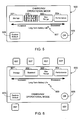
- Fig. 5 illustrates the display screen 500 of a touch-sensitive display system.
- Display screen 500 can be a stand-alone display screen or, as preferred, simply one display screen of a plurality of display screens comprising a user interface.
- this user interface allows the user to perform other functions associated with the operation of the vehicle, such as monitoring performance, monitoring battery life, monitoring the state of charge of the battery, monitoring the remaining miles to drive on the current battery charge, adjusting system default settings, and other monitoring/operational functions.
- This same user interface through additional screens, can also be used to provide the user with AC/heat controls, audio entertainment controls, cell phone controls, navigation system controls, and other convenience functions.
- Display screen 500 includes a plurality of touch-sensitive buttons 501-504 that correspond to the available charging/operational modes.
- touching one of the buttons 501-504 causes the corresponding mode to be selected.
- the touched button is highlighted to indicate the selection.
- button 502 is shown as highlighted.
- a mode selection button must be touched followed by pushing (i.e., touching) a data entry button 505. Requiring the selection of two buttons, i.e., the mode button and the entry button, decreases the risk of an inadvertent mode change.
- a secondary mode selection screen is displayed that requests a user personal identification number (PIN) or password.
- the charging/operational mode selection means includes some indicator that helps the user to recognize the effects of their mode selection.
- Fig. 5 indicator 507 graphically illustrates the effects of the different modes on battery life.
- each button can be color-coded.
- a secondary display screen can be displayed when the user makes a selection, the secondary display screen highlighting the effects of the selection.
- the display screen may provide an indication of the improved range (e.g., "range increased by 10%") and the effects on battery life (e.g., "decreases long-term battery life").
- buttons, toggle switches, or other switching means that are used in conjunction with the display to provide the selection means.
- Fig. 6 illustrates one such means.
- screen 600 is configured so that the possible modes 601-604 as well as other possible inputs 605-606 are immediately adjacent to hard buttons, or other switching means, 607.
- buttons/switches 607 can similarly be used to provide other data input simply by reconfiguring the display and associating the hard switches 607 with other functions.
- display screen 600 includes an indicator 609 that shows the user the effects of their selection.
- a simple non-display mode selector can also be used with the invention.
- a mode selector can be comprised solely of push buttons, toggle switches, slide switches, rotating switches, etc., which can be located within the passenger compartment (e.g., on the dash, on the console, etc.) or elsewhere (e.g., near the plug-in receptacle on the outside of the vehicle, preferably covered by a charging receptacle cover door).
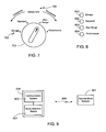
- Fig. 7 illustrates one such charging/operational mode selector that does not require a display interface, rather it uses a rotating switch 701.
- Indicators 703 surround switch 701, each of which indicates a particular charging/operational mode. In the illustration shown in Fig. 7 , four charging/operational modes are shown with the Max Range Mode selected. As in the prior embodiments, preferably an indicator is used, e.g., indicator 705, to insure that the user recognizes the effects of their selection on a system parameter (e.g., battery life).
- a system parameter e.g., battery life
- the charging/operational mode selection means uses a voice recognition system such as those commonly used with on-board vehicle navigation systems.
- the voice recognition system uses a display interface as well, thus simplifying system/user interaction and providing the user with positive indicators when their voice inputs have been correctly accepted by the system.
- the system includes one or more indicators that indicate the selected mode.
- the indicators are easily visible to insure that the user recognizes the selected mode.
- four indicators can be located on the dashboard, easily visible to the driver, representing the four charging/operational modes illustrated in Figs. 5-7 .
- Preferably next to each indicator is either a textual indicator of the mode, as shown in Fig. 8 , or a symbolic indicator of the mode.
- the indicators are also color coded, thus providing a secondary indicator of selected mode. For example, in the indicators shown in Fig. 8 , indicator 801 is blue, indicator 803 is green, indicator 805 is yellow and indicator 807 is red. This is but one of numerous ways in which the selected mode can be highlighted to the driver of the vehicle.
- a remote selection means can be employed.
- the primary advantage of this type of mode selector is that it allows the user to remotely alter the charging/operational mode. For example, while on a trip the user may find that their trip has been extended and that their vehicle will not be used for an extended period of time. Certain types of remote mode selectors would allow the user to change the mode to the Storage Mode, thereby improving battery life.
- Fig. 9 is a simplified illustration of a system for remote charging/operational mode selection.
- the system includes a remote mode selector 901 and an on-board communication system 903 that communicates with remote mode selector 901 via communication network 905.
- On-board communication system 903 is coupled to on-board mode selection means 907, both of which are contained within vehicle 909.
- remote mode selector 901 is an RF remote, therefore not requiring a communication network. Due to the limited range of an RF remote, in a preferred embodiment remote 901 communicates via network 905, network 905 being any of a variety of known network systems such as cellular, internet, satellite or other.
- the remote mode selector 901 is a computer or a web-browser on a cell phone and network 905 is an internet-based network system.
- network 905 is an internet-based network system.
- the system prompts the user to select a charging/operational mode.
- the user is prompted after turning off the car, but prior to exiting the car, for example when the user first turns the key (or other vehicle on/off control switch) from the operational/driving position to the standby/off position.
- the user can be prompted by a tone or series of tones, by a pre-recorded or synthesized voice, or by a display means (e.g., flashing indicator, flashing screen on the display interface, etc.), or a combination thereof.
- the default mode for the charging/operational mode selection system is the Standard Mode.
- the system resets to the default mode, i.e., Standard Mode, after each user selected charging/operational mode is complete.
- the default mode i.e., Standard Mode
- the system will remain in the Storage Mode as long as the vehicle remains in storage. Once the vehicle is taken out of storage, for example by operating the vehicle, the system automatically returns to the default mode.
- the user sets the system to the Performance Mode or the Max Range Mode, the vehicle stays in the selected mode during vehicle operation, but returns to the default mode the first time the user turns off the car or the next time the vehicle is plugged into an external power source for charging.
- the user is able to select the default mode for the charging/operational mode selection system.
- the user is also able to select the temporary charging/operational mode using the mode selection means as previously described.
- the mode changes from the preferred mode to the default mode after a preset period of time, or after the occurrence of a particular event such as the completion of the present driving cycle and the vehicle being changed from the operational mode to the charging mode, or after the occurrence of a particular event such as the vehicle being changed from the charging mode to the operational mode.
- the vehicle if the vehicle is not operated for a preset period of time, the vehicle automatically switches mode from the default mode (e.g., Standard Mode) to the Storage Mode.
- the vehicle preferably stays in the Storage Mode until the user either operates the vehicle or actively selects a different charging/operational mode.
- the user is able to set the preset time period, for example by choosing from a list of time periods (e.g., 1 week, 2 weeks, 3 weeks, etc.). This option allows the user to set-up the vehicle based on the user's particular driving habits, thus insuring that the vehicle is not unintentionally placed in the Storage Mode.
- the user is able to switch modes from the current mode to the Performance Mode while driving the vehicle.
- the switching means used to switch from the current mode into the Performance Mode is different from, and in addition to, the normal user mode selection means.
- the preset time period is preset by the vehicle's manufacturer.
- the preset time period is preset, or configurable, by a representative of the manufacturer such as an authorized service provider. Alternately, the preset time period is configurable by the user. Preferably if an embodiment of the invention is used which allows the user to switch from the current mode into the Performance Mode while driving, the embodiment is also configured to automatically revert to the Standard Mode, either after a predetermined time period (e.g., 24 hours) or upon completion of the present driving period (i.e., when power is turned off and the vehicle enters the standby mode) or upon completion of the present driving cycle (i.e., when power is turned off and the vehicle is plugged in to recharge battery pack 403).
- a predetermined time period e.g., 24 hours
- the present driving period i.e., when power is turned off and the vehicle enters the standby mode
- completion of the present driving cycle i.e., when power is turned off and the vehicle is plugged in to recharge battery pack 403
Landscapes
- Engineering & Computer Science (AREA)
- Power Engineering (AREA)
- Transportation (AREA)
- Mechanical Engineering (AREA)
- Life Sciences & Earth Sciences (AREA)
- Sustainable Development (AREA)
- Sustainable Energy (AREA)
- Charge And Discharge Circuits For Batteries Or The Like (AREA)
- Electric Propulsion And Braking For Vehicles (AREA)
- Secondary Cells (AREA)
- Battery Mounting, Suspending (AREA)
Abstract
Description
- The present invention relates generally to batteries and, more particularly, to a method and apparatus for providing different charging and cooling modes for the battery pack of an electric vehicle.
- Batteries have been used for decades to supply power to a variety of different electrical and electro-mechanical devices. Early batteries, referred to as disposable batteries, were simply used until depleted and then discarded and replaced with one or more new batteries. A newer type of battery, referred to as a rechargeable battery, is capable of being recharged and then reused, therefore offering economic, environmental and ease-of-use benefits compared to a disposable battery.
- Although rechargeable batteries provide a much longer service life than disposable batteries, their service life is not unlimited. Depending upon the type of battery, a rechargeable battery can typically be recharged anywhere from 100 times (e.g., alkaline) to 1000 times (e.g., lithium-ion, lithium-polymer) to 20,000 times or more (e.g., thin film lithium). In addition to depending upon the type of battery chemistry involved, the number of cycles that a rechargeable battery can be recharged depends on a variety of other factors that include; (i) the rate of charging (i.e., slow trickle charge versus fast charge), (ii) the level of charging (i.e., 75% of full charge, full charge, over-charged, etc.), (iii) the level of discharge prior to charging (i.e., completely depleted, still charged to a low level, etc.), (iv) the storage temperature of the battery during non-use, and (v) the temperature of the battery during use.
- Due to the high initial cost of rechargeable batteries, expensive products such as laptop computers often incorporate relatively sophisticated power management systems, thereby extending battery life and allowing the use of smaller, lower capacity batteries and/or batteries that utilize less expensive cell chemistries. One of the most common power management techniques is to place certain laptop components and peripherals, especially those that require relatively high levels of power to function, into either a standby mode or a low power usage mode whenever possible. Thus, for example, a laptop may provide two different video screen brightness levels; high brightness when the computer is plugged in, and low brightness when the computer is operating on battery power. This is also the primary purpose behind powering down the video screen when the computer is inactive for more than a short period of time or placing wireless connectivity capabilities (e.g., Bluetooth, WiFi, WAN, etc.) or other non-essential peripherals in standby mode when they are not required.
- A growing application for rechargeable batteries is that of electric vehicles. All-electric and hybrid vehicles, however, present a number of engineering challenges, primarily due to the need for the rechargeable battery pack of such a vehicle to meet the consumers' expectations relative to performance, range, reliability, lifetime and cost. The present invention provides a battery pack recharging system and user interface that helps achieve these goals.
- The present invention provides a method and apparatus that allows the end user to optimize the performance of an all-electric or hybrid vehicle, the vehicle including a battery charging system and a battery cooling system, wherein the preferred mode of operation is selected from a plurality of charging/operational modes using a selecting means, and wherein selection of a preferred mode of operation causes the charging system to utilize a specific cut-off voltage and the battery cooling system to maintain the battery pack within a specific temperature range.
- In at least one embodiment, an electric vehicle multi-mode charging and operating system is provided that is comprised of a battery charging system that utilizes a cut-off voltage selected from at least three cut-off voltages; a battery cooling system for maintaining the electric vehicle's battery pack within a first preset temperature range when the battery charging system is coupled to an external charging power source, wherein the first preset temperature range is selected from at least a first temperature range and a second temperature range; and user accessible means for selecting a preferred mode from a plurality of charging/operational modes. Selection of a first mode from the plurality of charging/operational modes results in the battery charging system utilizing a first cut-off voltage and the battery cooling system maintaining the battery pack within the first temperature range when the battery charging system is coupled to an external charging power source. Selection of a second mode from the plurality of charging/operational modes results in the battery charging system utilizing a second cut-off voltage and the battery cooling system maintaining the battery pack within the first temperature range when the battery charging system is coupled to an external charging power source. Selection of a third mode from the plurality of charging/operational modes results in the battery charging system utilizing a third cut-off voltage and the battery cooling system maintaining the battery pack within the second temperature range when the battery charging system is coupled to an external charging power source. The first preset temperature range may further comprise a third temperature range, wherein selection of a fourth mode from the plurality of charging/operational modes results in the battery charging system utilizing the third cut-off voltage and the battery cooling system maintaining the battery pack within the third temperature range when the battery charging system is coupled to an external charging power source.
- The battery cooling system may maintain the battery pack within a second preset temperature range when the battery charging system is not coupled to an external charging power source, wherein the second preset temperature range is selected from at least a third temperature range and a fourth temperature range. Selection of the first mode from the plurality of charging/operational modes results in the battery cooling system maintaining the battery pack within the third temperature range when the battery charging system is not coupled to an external charging power source. Selection of the third mode from the plurality of charging/operational modes results in the battery cooling system maintaining the battery pack within the fourth temperature range when the battery charging system is not coupled to an external charging power source.
- The electric vehicle multi-mode battery charging and operating system may further comprise a battery heating system for preventing a battery pack temperature from falling below a preset temperature threshold when the battery charging system is not coupled to an external charging power source and when the third mode is selected.
- The electric vehicle multi-mode battery charging and operating system may further comprise a battery heating system for preventing a battery pack temperature from falling below a preset temperature threshold when the battery charging system is coupled to an external charging power source and when the fourth mode is selected.
- The selecting means of the electric vehicle multi-mode battery charging and operating system may utilize a touch-sensitive screen, a display system, a plurality of switching means (e.g., push-buttons, toggle switches, rotating switches and slide switches), a voice recognition system, or a remote mode selector. The system may further include at least one mode indicator. The system may further include means for switching between the preferred mode and a default mode. The system may further include user accessible means for selecting the default mode from the plurality of charging/operational modes.
- In at least one embodiment of the invention, a method of setting a charging/operational mode of an electric vehicle is provided, the method comprising the steps of displaying a plurality of user accessible charging/operational modes, selecting a preferred mode from the plurality of user accessible charging/operational modes, displaying an indicator of the selected mode, adjusting a cut-off voltage and maintaining the temperature of the battery pack within a range of temperatures when the electric vehicle is plugged into an external charging power source, wherein the cut-off voltage and the temperature range are based on the selected mode. The method may further comprise the step of maintaining the temperature of the battery pack within a range of temperatures when the electric vehicle is not plugged into an external charging power source, wherein the temperature range is based on the selected mode. The method may further comprise the step of reverting to a default charging/operational mode from the preferred charging/operational mode after a preset period of time, or after the electric vehicle has cycled from an operational mode to a standby mode.
- A further understanding of the nature and advantages of the present invention may be realized by reference to the remaining portions of the specification and the drawings.
-
-
Fig. 1 graphically illustrates the effects of charging cut-off voltage on battery life; -
Fig. 2 graphically illustrates the effects of temperature on cell voltage and discharge capacity; -
Fig. 3 graphically illustrates the effects of storage temperature on battery capacity; -
Fig. 4 is a high-level view of the primary vehicle subsystems impacted by a battery charging system designed in accordance with a preferred embodiment of the invention; -
Fig. 5 illustrates a touch-sensitive display screen associated with one embodiment of a charging/operational mode selector; -
Fig. 6 illustrates a non-touch-sensitive display used in conjunction with other switching means in an alternate embodiment of a charging/operational mode selector; -
Fig. 7 illustrates a simple charging/operational mode selector that does not require a display interface; -
Fig. 8 illustrates a simple means of indicating the selected charging/operational mode; and -
Fig. 9 illustrates a system for remote charging/operational mode selection. - In the following text, the terms "battery", "cell", and "battery cell" may be used interchangeably and may refer to any of a variety of different rechargeable cell chemistries and configurations including, but not limited to, lithium ion (e.g., lithium iron phosphate, lithium cobalt oxide, other lithium metal oxides, etc.), lithium ion polymer, nickel metal hydride, nickel cadmium, nickel hydrogen, nickel zinc, silver zinc, or other battery type/configuration. The term "battery pack" as used herein refers to multiple individual batteries contained within a single piece or multi-piece housing, the individual batteries electrically interconnected to achieve the desired voltage and capacity for a particular application. The term "electric vehicle" as used herein refers to either an all electric vehicle, also referred to as an EV, plug-in hybrid vehicles, also referred to as a PHEV, or a hybrid vehicle (HEV), a hybrid vehicle utilizing multiple propulsion sources one of which is an electric drive system.
-
Figs. 1-3 illustrate several battery characteristics for an exemplary battery pack. It should be understood that different battery packs, for example those using a different cell chemistry, will exhibit different profiles than those shown inFigs. 1-3 , and that these figures are only meant to be illustrative, not limiting. -
Fig. 1 is a graph that illustrates the effects of charging cut-off voltage on battery life, the cut-off voltage being the voltage at which charging is terminated. Utilizing a cut-off voltage of 4.15 volts (curve 101), initially the battery pack achieves a higher capacity than that obtained using a cut-off voltage of 4.10 volts (curve 103). However, after approximately 200 charging cycles, the capacity of the battery using the lower cut-off voltage is greater than that of the battery using the higher cut-off voltage, illustrating that the useful lifetime of a battery pack can be dramatically extended by simply lowering cut-off voltage. Unfortunately lowering the cut-off voltage has consequences to other aspects of the battery pack's performance, in particular capacity, since a battery charged to a higher voltage exhibits a greater capacity than the same battery charged to a lower voltage. -
Fig. 2 is a graph illustrating the effects of temperature on the cell voltage and discharge capacity of an exemplary battery. In the figure,curve 201 corresponds to a temperature of 40° C,curve 202 corresponds to a temperature of 30° C, andcurve 203 corresponds to a temperature of 20° C. As illustrated, an increase in operating temperature from 20° C to 40° C dramatically improves discharge capacity which, in turn, can lead to both improved vehicle performance (e.g., faster acceleration) and improved driving range for an electric vehicle using such a battery pack. A drawback, however, of operating at a higher temperature is the effect such a temperature has on battery life, specifically shortening the battery's life. Another adverse effect of higher temperatures is that a battery will typically exhibit higher non-recoverable capacity loss as the temperature is increased. This battery characteristic is illustrated inFig. 3 in whichcurve 301 is for a battery pack cycled at 35° C andcurve 303 is for a battery pack cycled at 55° C. As shown, by decreasing the storage temperature of a battery, it is able to retain a much higher capacity over a longer cycle life. - There are many other battery characteristics that must be taken into account during the design of the drive system, battery pack and attendant charging system of an all-electric or hybrid vehicle. For example, the depth of discharge which the system allows, or that the system is designed to accommodate, will affect a battery's life. For most battery chemistries, frequently discharging the battery more than 70 to 80 percent of rated capacity will lead to decreases in battery life.
-
Fig. 4 is a high-level view of the primary vehicle subsystems impacted by a battery charging system designed in accordance with a preferred embodiment of the invention. It will be appreciated that a vehicle can utilize other subsystem configurations while still retaining the multi-charging mode capabilities of the present invention. As shown,system 400 includes apower control subsystem 401, abattery pack 403, abattery cooling subsystem 405, abattery heating subsystem 407, and auser interface 409. In a preferred embodiment,battery cooling system 405 andbattery heating system 407 are combined into atemperature management system 408. -
Power control subsystem 401 is comprised of acharging module 411 that controls and monitors cut-off voltage during charging.Charging module 411 may also control and monitor the charging rate. Preferably, and as described in further detail below,power control subsystem 401 also monitors the temperature ofbattery pack 403 and controls that temperature usingbattery cooling subsystem 405. In at least one embodiment, abattery heating subsystem 407 is also used bypower control subsystem 401 to achieve the desired battery pack operating and/or storage temperature. An exemplary battery temperature control system is described in detail in co-pendingU.S. Patent Application Serial No. 11/786,108, filed April 11, 2007 -
Power control subsystem 401 also monitors the state of charge forbattery pack 403, for example via chargingmodule 411. Preferablysubsystem 401 is also capable of monitoring the rate of discharge ofbattery pack 403, both during vehicle operation and vehicle storage. In addition, in at least oneembodiment subsystem 401 monitors and stores in on-board memory the number of charging cycles to which the battery has been subjected. Preferably for each charging cycle the cut-off voltage and other charging parameters are monitored and stored in memory, thereby providing information that can be used to gauge the relative health ofbattery pack 403 and its expected lifetime. - Although charging
module 411 is preferably integrated withinpower control subsystem 401 as shown, in at least one alternateembodiment charging module 411 is external to both thepower control subsystem 401 and the vehicle. In such an embodiment, preferably the portion of the charging module that converts external power to a power level (e.g., voltage) that is compatible withbattery pack 403 is external to the vehicle while a second portion of the charging module that controls charging characteristics such as cut-off voltage, charging rate, etc. is internal to the vehicle. Alternately, the entire charging module can be external to thepower control subsystem 401 and the vehicle. - In at least one preferred embodiment,
battery pack 403 is configured to be plugged into, or otherwise connected to, anexternal power source 413 via chargingmodule 411. A municipal power grid is one example of anexternal power source 413.Charging module 411 insures that the power fromsource 413 is converted to a form of power storable bybattery pack 403. For example, chargingmodule 411 typically includes an AC to DC rectifier in order to convert power from the power source to that required bybattery pack 403. In at least one embodiment,battery pack 403 is charged in whole or in part by apower generator 415 that is contained within the vehicle, i.e., an on-board power generator, which is coupled to the battery pack via chargingmodule 411. As on-board power generator 415 is not necessary to the implementation of the invention, it is shown in phantom. It will be appreciated that in some embodiments, whileexternal power source 413 is preferred for providing a full charge tobattery pack 403,internal power source 415 can be used to augment the charge within the battery pack, for example by chargingbattery pack 403 during vehicle use, thereby extending driving range. In at least one embodiment,internal power source 415 is a regenerative braking system. -
Power control subsystem 401 also controls the power coupled frombattery pack 403 tovehicle propulsion motor 417, for example using a power electronics module (PEM) 419.Power electronics module 419 is used to insure that the power delivered tomotor 417 has the desired voltage, current, waveform, etc. Thus, for example,power electronics module 419 preferably includes a DC to AC inverter, as well as the necessary control circuitry/processor to implement the various selectable charge modes as described in detail below. It will be appreciated thatvehicle propulsion motor 417 can be comprised of a single electric motor, or multiple electric motors. -
User interface 409 is preferably integrated into the vehicle's user interface, althoughinterface 409 can be implemented in other ways as described in detail below.Interface 409 provides a means for the user to control the selection of the charging mode as well as associated parameters. Preferably interface 409 also provides means for identifying which mode the vehicle is in at any given time, as described further below. - The system of the present invention allows the user to select the operational mode of a vehicle, more specifically aspects of the charging, battery and power control systems that affect the performance of an electric vehicle (i.e., all electric or hybrid) and the battery pack, as well as the life expectancy of the battery pack. Preferred modes of operation will now be described in detail.
- Standard Mode - In the Standard Mode, the system is configured to provide the optimal compromise between performance, driving range and battery life. In general, the Standard Mode will limit the cut-off voltage during charging to approximately 70%-95% of the rated capacity. In a preferred embodiment, the cut-off voltage in the Standard Mode is set to approximately 4.10 volts. The Standard Mode is intended to maintain the battery pack at a relatively cool temperature during both vehicle operation (i.e., driving) and when plugged in, preferably cooling the battery pack to a temperature within the range of approximately 30° C to 35° C during vehicle operation, and within the range of approximately 20° C to 25° C when the vehicle is plugged in to the external power source.
- Storage Mode - The Storage Mode is configured to optimize battery life when the vehicle is stored for an extended period of time, for example, for a period of time greater than 2 or 3 weeks. In this mode, the cut-off voltage during charging is limited to approximately 30%-70%, and more preferably to approximately 30%-50%. In a preferred embodiment, the cut-off voltage in the Storage Mode is set to approximately 3.80 volts. As in the Standard Mode, the battery pack temperature is maintained at a relatively cool temperature, preferably in the range of approximately 20° C to 25° C, when the charging system is coupled to an external power source. In at least one embodiment, once Storage Mode is selected, and assuming that the vehicle is plugged in rather than operating and that the battery pack's state of charge is greater than a preset value (e.g., 50%), the system actively lowers the charge state to the preset value, thereby helping to prolong battery life. Preferably the system actively lowers the charge state by subjecting the battery pack to a load (e.g., turning on a light(s), fan, dummy load, etc.).
- Extended Driving Range Mode - This mode, also referred to as the Max Range Mode, optimizes the system for maximum driving range, i.e., distance. During vehicle operation, the battery is kept relatively warm, thereby decreasing battery impedance and achieving greater discharge capacity. In a preferred embodiment, during vehicle operation in this mode, the temperature is not cooled until the temperature rises to about 40° C. The cooling system then operates to keep it within the range of approximately 37° C to 40° C. If the Max Range Mode is selected and the vehicle is plugged into an external power source, the battery pack is cooled to a lower temperature than normal, preferably in the range of approximately 15° C to 17° C. During charging the maximum cut-off voltage is used, i.e., approximately 90% - 100% of rated capacity. In the preferred embodiment, the cut-off voltage is set to approximately 4.15 - 4.18 volts.
- Performance Mode - This mode is intended to achieve the best vehicle performance available, at the cost of both battery life and range. In general, the Performance Mode uses the maximum cut-off voltage during charging, i.e., approximately 90% - 100%. In one embodiment, the maximum cut-off voltage is set to approximately 4.15 to 4.18 volts. In a preferred embodiment, during vehicle operation the battery pack temperature is allowed to rise to a temperature within the range of approximately 37° C to 40° C and then cooled to maintain the temperature within this range. In this mode when the vehicle is plugged into the external power source, preferably the battery temperature is cooled (if necessary) to a temperature within the range of approximately 35° C to 40° C.
- In at least one alternate embodiment, in addition to the above-described battery pack cooling conditions, when the vehicle is plugged in pre-heating is used, as necessary, to insure that the battery pack temperature does not fall below a preset temperature, for example 33° C. In particular, in this alternate embodiment the battery preheater is enabled when the battery temperature falls below 33° C, and is then disabled once a temperature of 35° C is reached.
- In addition to charging the battery pack to the maximum level and maintaining the battery at a relatively high temperature, in at least one embodiment when the user selects the Performance Mode, the power control subsystem via the power electronics module provides an additional performance boost. Specifically, in this embodiment when the Performance Mode is selected, the system provides a temporary increase in the available current that can be supplied to
motor 417. In an exemplary system, the available current is increased from 850 amps rms to 900 amps rms. As the increase in current stresses many vehicle components (e.g.,PEM 419, motor shaft, transmission, etc.), preferably the current boost is of very limited duration. For example in one embodiment, the current boost is only allowed for a maximum duration of 5 seconds. Preferably other limitations are placed on the current boost, for example limiting it to one use per Performance Mode selection. In order to limit system stress, the current boost can also be limited to a predetermined number of times per time period, the time period being measured in days, weeks or months. - It will be appreciated that the cut-off voltages as well as the optimal temperature ranges provided above relative to the described charging/operational modes of operation are based on a specific vehicle and battery pack. The inventors envision that other vehicles and/or battery types may require different operational parameters (e.g., cut-off voltages, battery temperatures, etc.) in order to achieve the desired goals of optimizing the charging, battery and power control systems for such specific charging/operational modes as Standard Mode, Storage Mode, Extended Driving Range Mode and Performance Mode.
- In a preferred embodiment of the invention, if the vehicle is plugged into
external power source 413 during any of the above modes and battery pack charging has been completed, in addition to initiating battery pack cooling in order to keep the battery within the preset temperature range, charging is re-initiated so that the battery is not used topower cooling subsystem 405. Charging re-initiation can start before, after, or at the same time as cooling subsystem initiation. - In at least one embodiment, the selection of a specific charging/operational mode also impacts the charging profile employed while operating the vehicle. This embodiment requires some form of an
internal power generator 415. Preferablyinternal power generator 415 utilizes a regenerative braking system, either alone or in combination with other power generation means (e.g., roof-mounted solar panels, etc.). In this embodiment, the state of charge ofbattery pack 403 is monitored and maintained within a predefined range using the charging capabilities provided by the internal power generator. Preferably, in the Standard Mode an average charge of approximately 50% is maintained; in the Storage Mode an average charge of 30-50% is maintained; and in the Max Range and the Performance Modes an average charge of approximately 70% is maintained. - In at least one embodiment, when the vehicle is plugged into
external power source 413, thepower control subsystem 401 determines the voltage and current of the source. If the voltage is less than a preset value, e.g., 150 volts, or if the line current is less than or equal to a preset value, e.g., 12 amps, battery cooling is limited. This approach can be used, for example, to shorten charge time. In a specific application, whensubsystem 401 determines that the voltage/current of the external power source is less than the preset value, the battery temperature is cooled to a temperature within the range of approximately 37° C to 40° C regardless of the charging/operational mode selected, and once the battery pack temperature is less than 37° C, the cooling subsystem is disabled. - In an alternate embodiment of the invention, the system of the present invention allows the user to select a mode based on one or more battery/power system characteristics. For example, in one such embodiment, means (e.g., dial, menu based system on a visual display, buttons, etc.) are provided that allow the user to select the charging cut-off voltage. Preferably the user is given four or more options such as 3.8 volts, 3.9 volts, 4.0 volts, 4.1 volts and 4.15 volts. Alternately, the provided means allow the user to select the average charge, e.g., 30%, 40%, 50%, 60%, 70%, 80%, 90% and 100%.
- In this alternate embodiment, means are preferably used to indicate to the user both the advantages and the disadvantages for each selection. For example, a display monitor can graphically illustrate that as the cut-off voltage is increased, the user is gaining performance and driving range while negatively impacting battery life. In one relatively simple display, the user is shown a sliding scale (e.g., from minimum driving range to maximum driving range) with an indicator on the scale showing the user's selection. In an example of a relatively complex display, the system calculates the effects of the user's selection on predicted battery life or on the vehicle's driving range.
- In this alternate embodiment, preferably the
power control subsystem 401 sets additional system parameters based on the user's selection. For example, as the selected cut-off voltage is increased, the system can automatically increase battery temperature as well as the cut-off voltage, assuming that if the user selects a higher cut-off voltage, they are less interested in battery life and more interested in performance. In at least one such embodiment, the power control subsystem uses a look-up table to determine appropriate battery temperatures, charging characteristics, etc., all based on the user's selection. - The present invention can utilize any of a variety of charging/operational mode selection means. In a preferred embodiment, a display system is used, either alone with a touch-sensitive screen, or together with a plurality of switching means (e.g., toggle switches, push button switches, slide switches, etc.). For example,
Fig. 5 illustrates thedisplay screen 500 of a touch-sensitive display system.Display screen 500 can be a stand-alone display screen or, as preferred, simply one display screen of a plurality of display screens comprising a user interface. Preferably this user interface allows the user to perform other functions associated with the operation of the vehicle, such as monitoring performance, monitoring battery life, monitoring the state of charge of the battery, monitoring the remaining miles to drive on the current battery charge, adjusting system default settings, and other monitoring/operational functions. This same user interface, through additional screens, can also be used to provide the user with AC/heat controls, audio entertainment controls, cell phone controls, navigation system controls, and other convenience functions. -
Display screen 500 includes a plurality of touch-sensitive buttons 501-504 that correspond to the available charging/operational modes. In one embodiment, touching one of the buttons 501-504 causes the corresponding mode to be selected. Preferably the touched button is highlighted to indicate the selection. InFig. 5 ,button 502 is shown as highlighted. In an alternate embodiment, a mode selection button must be touched followed by pushing (i.e., touching) adata entry button 505. Requiring the selection of two buttons, i.e., the mode button and the entry button, decreases the risk of an inadvertent mode change. In an alternate embodiment that is intended to further reduce the risk of inadvertent or unauthorized mode changes, after selecting a mode, or after selecting a mode and touching the data entry button, a secondary mode selection screen is displayed that requests a user personal identification number (PIN) or password. - Preferably the charging/operational mode selection means includes some indicator that helps the user to recognize the effects of their mode selection. In
Fig. 5 indicator 507 graphically illustrates the effects of the different modes on battery life. It will be appreciated that there are numerous ways in which such an indication can be made and that are clearly envisioned by the inventors. For example, each button can be color-coded. Alternately, a secondary display screen can be displayed when the user makes a selection, the secondary display screen highlighting the effects of the selection. For example, when the user selects the Max Range Mode, the display screen may provide an indication of the improved range (e.g., "range increased by 10%") and the effects on battery life (e.g., "decreases long-term battery life"). - As previously noted, there are numerous other ways of configuring the charging/operational mode selection means. For example, if a non-touch-sensitive display is used, preferably the screen is immediately adjacent to a plurality of buttons, toggle switches, or other switching means that are used in conjunction with the display to provide the selection means.
Fig. 6 illustrates one such means. As shown,screen 600 is configured so that the possible modes 601-604 as well as other possible inputs 605-606 are immediately adjacent to hard buttons, or other switching means, 607. It will be appreciated that buttons/switches 607 can similarly be used to provide other data input simply by reconfiguring the display and associating thehard switches 607 with other functions. As in the previous example,display screen 600 includes anindicator 609 that shows the user the effects of their selection. - In addition to a charging/operational mode selector that uses a display screen, e.g., displays 500 and 600, as previously noted a simple non-display mode selector can also be used with the invention. For example, such a mode selector can be comprised solely of push buttons, toggle switches, slide switches, rotating switches, etc., which can be located within the passenger compartment (e.g., on the dash, on the console, etc.) or elsewhere (e.g., near the plug-in receptacle on the outside of the vehicle, preferably covered by a charging receptacle cover door).
Fig. 7 illustrates one such charging/operational mode selector that does not require a display interface, rather it uses arotating switch 701.Indicators 703surround switch 701, each of which indicates a particular charging/operational mode. In the illustration shown inFig. 7 , four charging/operational modes are shown with the Max Range Mode selected. As in the prior embodiments, preferably an indicator is used, e.g.,indicator 705, to insure that the user recognizes the effects of their selection on a system parameter (e.g., battery life). - In another embodiment, the charging/operational mode selection means uses a voice recognition system such as those commonly used with on-board vehicle navigation systems. Preferably the voice recognition system uses a display interface as well, thus simplifying system/user interaction and providing the user with positive indicators when their voice inputs have been correctly accepted by the system.
- Regardless of the selection means used, preferably the system includes one or more indicators that indicate the selected mode. Preferably the indicators are easily visible to insure that the user recognizes the selected mode. For example, four indicators can be located on the dashboard, easily visible to the driver, representing the four charging/operational modes illustrated in
Figs. 5-7 . Preferably next to each indicator is either a textual indicator of the mode, as shown inFig. 8 , or a symbolic indicator of the mode. In at least one embodiment, the indicators are also color coded, thus providing a secondary indicator of selected mode. For example, in the indicators shown inFig. 8 ,indicator 801 is blue,indicator 803 is green, indicator 805 is yellow and indicator 807 is red. This is but one of numerous ways in which the selected mode can be highlighted to the driver of the vehicle. - In addition to, or instead of, an on-board charging/operational mode selection means, a remote selection means can be employed. The primary advantage of this type of mode selector is that it allows the user to remotely alter the charging/operational mode. For example, while on a trip the user may find that their trip has been extended and that their vehicle will not be used for an extended period of time. Certain types of remote mode selectors would allow the user to change the mode to the Storage Mode, thereby improving battery life.
-
Fig. 9 is a simplified illustration of a system for remote charging/operational mode selection. As shown, the system includes aremote mode selector 901 and an on-board communication system 903 that communicates withremote mode selector 901 viacommunication network 905. On-board communication system 903 is coupled to on-board mode selection means 907, both of which are contained withinvehicle 909. In the simplest form,remote mode selector 901 is an RF remote, therefore not requiring a communication network. Due to the limited range of an RF remote, in a preferred embodiment remote 901 communicates vianetwork 905,network 905 being any of a variety of known network systems such as cellular, internet, satellite or other. For example, in one embodiment theremote mode selector 901 is a computer or a web-browser on a cell phone andnetwork 905 is an internet-based network system. Further descriptions of suitable vehicle communication systems are given in co-pendingU.S. Patent Application Serial Nos. 11/818,838, filed June 15, 2007 11/779,678, filed July 18, 2007 - In at least one embodiment of the invention, the system prompts the user to select a charging/operational mode. Preferably the user is prompted after turning off the car, but prior to exiting the car, for example when the user first turns the key (or other vehicle on/off control switch) from the operational/driving position to the standby/off position. The user can be prompted by a tone or series of tones, by a pre-recorded or synthesized voice, or by a display means (e.g., flashing indicator, flashing screen on the display interface, etc.), or a combination thereof.
- In one preferred embodiment, the default mode for the charging/operational mode selection system is the Standard Mode. In this embodiment, the system resets to the default mode, i.e., Standard Mode, after each user selected charging/operational mode is complete. Thus, for example, if the user selects the Storage Mode, the system will remain in the Storage Mode as long as the vehicle remains in storage. Once the vehicle is taken out of storage, for example by operating the vehicle, the system automatically returns to the default mode. Similarly, if the user sets the system to the Performance Mode or the Max Range Mode, the vehicle stays in the selected mode during vehicle operation, but returns to the default mode the first time the user turns off the car or the next time the vehicle is plugged into an external power source for charging.
- In at least one embodiment of the invention, the user is able to select the default mode for the charging/operational mode selection system. The user is also able to select the temporary charging/operational mode using the mode selection means as previously described. Preferably the mode changes from the preferred mode to the default mode after a preset period of time, or after the occurrence of a particular event such as the completion of the present driving cycle and the vehicle being changed from the operational mode to the charging mode, or after the occurrence of a particular event such as the vehicle being changed from the charging mode to the operational mode.
- In at least one embodiment of the invention, if the vehicle is not operated for a preset period of time, the vehicle automatically switches mode from the default mode (e.g., Standard Mode) to the Storage Mode. The vehicle preferably stays in the Storage Mode until the user either operates the vehicle or actively selects a different charging/operational mode. Preferably in this embodiment the user is able to set the preset time period, for example by choosing from a list of time periods (e.g., 1 week, 2 weeks, 3 weeks, etc.). This option allows the user to set-up the vehicle based on the user's particular driving habits, thus insuring that the vehicle is not unintentionally placed in the Storage Mode.
- In at least one embodiment of the invention, the user is able to switch modes from the current mode to the Performance Mode while driving the vehicle. Preferably the switching means used to switch from the current mode into the Performance Mode is different from, and in addition to, the normal user mode selection means. For example, in one embodiment if the user completely depresses the accelerator pad more than once within a preset time period, for example in a 3 second time period, than the charging/operational mode switches to the Performance Mode. In an alternate embodiment, if the user completely depresses the accelerator pad more than twice within the preset time period than the charging/operational mode switches to the Performance Mode. Preferably the preset time period is preset by the vehicle's manufacturer. Alternately, the preset time period is preset, or configurable, by a representative of the manufacturer such as an authorized service provider. Alternately, the preset time period is configurable by the user. Preferably if an embodiment of the invention is used which allows the user to switch from the current mode into the Performance Mode while driving, the embodiment is also configured to automatically revert to the Standard Mode, either after a predetermined time period (e.g., 24 hours) or upon completion of the present driving period (i.e., when power is turned off and the vehicle enters the standby mode) or upon completion of the present driving cycle (i.e., when power is turned off and the vehicle is plugged in to recharge battery pack 403).
- As will be understood by those familiar with the art, the present invention may be embodied in other specific forms without departing from the spirit or essential characteristics thereof. Accordingly, the disclosures and descriptions herein are intended to be illustrative, but not limiting, of the scope of the invention which is set forth in the following claims.
Claims (26)
- An electric vehicle multi-mode battery charging and operating system, comprising:a battery charging system for charging a battery pack of an electric vehicle, said battery charging system utilizing a cut-off voltage selected from at least a first cut-off voltage, a second cut-off voltage, and a third cut-off voltage;a battery cooling system for cooling said battery pack of said electric vehicle, wherein said battery cooling system has at least a first mode of operation, said first mode of operation applied when said battery charging system is coupled to an external charging power source, wherein said battery cooling system in said first mode of operation maintains said battery pack within a first preset temperature range, wherein said first preset temperature range is selected from at least a first temperature range and a second temperature range; andmeans for selecting a preferred mode from a plurality of charging/operational modes, wherein said selecting means is accessible by a user of said electric vehicle, wherein a first mode of said plurality of charging/operational modes utilizes said first cut-off voltage, wherein a second mode of said plurality of charging/operational modes utilizes said second cut-off voltage, wherein a third mode of said plurality of charging/operational modes utilizes said third cut-off voltage, wherein said first mode of said plurality of charging/operational modes utilizes said first temperature range when said battery cooling system is in said first mode of operation, wherein said second mode of said plurality of charging/operational modes utilizes said first temperature range when said battery cooling system is in said first mode of operation, and wherein said third mode of said plurality of charging/operational modes utilizes said second temperature range when said battery cooling system is in said first mode of operation.
- The electric vehicle multi-mode battery charging and operating system of claim 1, wherein said first cut-off voltage is approximately 4.10 volts, said second cut-off voltage is approximately 3.80 volts, said third cut-off voltage is at least 4.15 volts, said first temperature range is approximately 20° C to 25° C, and said second temperature range is approximately 15° C to 17° C.
- The electric vehicle multi-mode battery charging and operating system of claims 1 or 2, wherein said battery cooling system has a second mode of operation applied when said battery charging system is not coupled to said external charging power source, wherein said battery cooling system in said second mode of operation maintains said battery pack within a second preset temperature range, wherein said second preset temperature range is selected from at least a third temperature range and a fourth temperature range, wherein said first mode of said plurality of charging/operational modes utilizes said third temperature range when said battery cooling system is in said second mode of operation, and wherein said third mode of said plurality of charging/operational modes utilizes said fourth temperature range when said battery cooling system is in said second mode of operation.
- The electric vehicle multi-mode battery charging and operating system of claim 3, wherein said third temperature range is approximately 30° C to 35° C, and said fourth temperature range is approximately 37° C to 40° C.
- The electric vehicle multi-mode battery charging and operating system of claims 1 or 2, wherein said first preset temperature range further includes a third temperature range, wherein a fourth mode of said plurality of charging/operational modes utilizes said third cut-off voltage, and wherein said fourth mode of said plurality of charging/operational modes utilizes said third temperature range when said battery cooling system is in said first mode of operation.
- The electric vehicle multi-mode battery charging and operating system of claim 5, wherein said third temperature range is approximately 35° C to 40° C.
- The electric vehicle multi-mode battery charging and operating system of claims 1 or 2, wherein said first preset temperature range further includes a third temperature range, wherein said battery cooling system has a second mode of operation applied when said battery charging system is not coupled to said external charging power source, wherein said battery cooling system in said second mode of operation maintains said battery pack within a second preset temperature range, wherein said second preset temperature range is selected from at least a fourth temperature range and a fifth temperature range, wherein said first mode of said plurality of charging/operational modes utilizes said fourth temperature range when said battery cooling system is in said second mode of operation, wherein said third mode of said plurality of charging/operational modes utilizes said fifth temperature range when said battery cooling system is in said second mode of operation, wherein a fourth mode of said plurality of charging/operational modes utilizes said third cut-off voltage, wherein said fourth mode of said plurality of charging/operational modes utilizes said third temperature range when said battery cooling system is in said first mode of operation, and wherein said fourth mode of said plurality of charging/operational modes utilizes said fifth temperature range when said battery cooling system is in said second mode of operation.
- The electric vehicle multi-mode battery charging and operating system of claim 7, wherein said third temperature range is approximately 35° C to 40° C, said fourth temperature range is approximately 30° C to 35° C, and wherein said fifth temperature range is approximately 37° C to 40° C.
- The electric vehicle multi-mode battery charging and operating system of claims 3 or 7, further comprising a battery heating system for preventing a battery pack temperature from falling below a preset temperature threshold when said battery charging system is not coupled to said external charging power source and when said third mode is selected by said selecting means.
- The electric vehicle multi-mode battery charging and operating system of claim 9, wherein said preset temperature is approximately 35° C.
- The electric vehicle multi-mode battery charging and operating system of claims 5 or 7, further comprising a battery heating system for preventing a battery pack temperature from falling below a preset temperature threshold when said battery charging system is coupled to said external charging power source and when said fourth mode is selected by said selecting means.
- The electric vehicle multi-mode battery charging and operating system of claim 11, wherein said preset temperature is approximately 33° C.
- The electric vehicle multi-mode battery charging and operating system of claims 1, 3, 5 or 7, wherein said selecting means is comprised of a touch-sensitive screen.
- The electric vehicle multi-mode battery charging and operating system of claims 1, 3, 5 or 7, wherein said selecting means is comprised of a display system.
- The electric vehicle multi-mode battery charging and operating system of claims 1, 3, 5, 7 or 14, wherein said selecting means is comprised of a plurality of switching means.
- The electric vehicle multi-mode battery charging and operating system of claim 15, wherein said switching means are selected from the group consisting of push-buttons, toggle switches, rotating switches and slide switches.
- The electric vehicle multi-mode battery charging and operating system of claims 1, 3, 5 or 7, wherein said selecting means is comprised of a voice recognition system.
- The electric vehicle multi-mode battery charging and operating system of claims 1, 3, 5 or 7, further comprising a communication interface in communication with a network, wherein said selecting means is a remote mode selector in communication with said network, wherein said remote mode selector is separate from said electric vehicle.
- The electric vehicle multi-mode battery charging and operating system of claims 1, 3, 5 or 7, further comprising at least one mode indicator, wherein said at least one mode indicator indicates which mode of said plurality of charging/operational modes is selected by said selecting means.
- The electric vehicle multi-mode battery charging and operating system of claims 1, 3, 5 or 7, wherein said first mode of said plurality of charging/operational modes is a default mode, said electric vehicle multi-mode battery charging and operating system further comprising means for switching from said preferred mode to said default mode upon the occurrence of a preset condition.
- The electric vehicle multi-mode battery charging and operating system of claims 1, 3, 5 or 7, further comprising means for selecting a default mode from said plurality of charging/operational modes, wherein said default mode selecting means is accessible by a user of said electric vehicle, and wherein said electric vehicle multi-mode battery charging and operating system further comprises means for switching from said preferred mode to said default mode upon the occurrence of a preset condition.
- A method of setting a charging/operational mode of an electric vehicle, the method comprising the steps of:displaying a plurality of user accessible charging/operational modes;selecting a preferred mode from said plurality of user accessible charging/operational modes;displaying an indicator of said selected preferred mode;adjusting a charging cut-off voltage to a first cut-off voltage in response to selecting a first mode as said preferred mode;cooling a battery pack of said electric vehicle to a battery pack temperature within a first range of temperatures in response to selecting said first mode as said preferred mode, wherein said step of cooling said battery pack to said battery pack temperature within said first range of temperatures is performed after said electric vehicle is coupled to an external charging power source;adjusting said charging cut-off voltage to a second cut-off voltage in response to selecting a second mode as said preferred mode;cooling said battery pack of said electric vehicle to said battery pack temperature within said first range of temperatures in response to selecting said second mode as said preferred mode, wherein said step of cooling said battery pack to said battery pack temperature within said first range of temperatures is performed after said electric vehicle is coupled to said external charging power source;adjusting said charging cut-off voltage to a third cut-off voltage in response to selecting a third mode as said preferred mode; andcooling said battery pack of said electric vehicle to said battery pack temperature within a second range of temperatures in response to selecting said third mode as said preferred mode, wherein said step of cooling said battery pack to said battery pack temperature within said second range of temperatures is performed after said electric vehicle is coupled to said external charging power source.
- The method of claim 22, further comprising the steps of ;
adjusting said charging cut-off voltage to said third cut-off voltage in response to selecting a fourth mode as said preferred mode; and
cooling said battery pack of said electric vehicle to said battery pack temperature within a third range of temperatures in response to selecting said fourth mode as said preferred mode, wherein said step of cooling said battery pack to said battery pack temperature within said third range of temperatures is performed after said electric vehicle is coupled to said external charging power source. - The method of claims 22 or 23, further comprising the steps of;
cooling said battery pack of said electric vehicle to said battery pack temperature within a fourth range of temperatures in response to selecting said first mode as said preferred mode, wherein said step of cooling said battery pack to said battery pack temperature within said fourth range of temperatures is performed while said electric vehicle is operating and when said electric vehicle is not coupled to said external charging power source; and
cooling said battery pack of said electric vehicle to said battery pack temperature within a fifth range of temperatures in response to selecting said third mode as said preferred mode, wherein said step of cooling said battery pack to said battery pack temperature within said fifth range of temperatures is performed while said electric vehicle is operating and when said electric vehicle is not coupled to said external charging power source. - The method of claims 22, 23 or 24, further comprising the step of reverting to a default mode from said preferred mode after a preset period of time, wherein said default mode is one of said plurality of user accessible charging/operational modes.
- The method of claims 22, 23 or 24, further comprising the step of reverting to a default mode from said preferred mode after said electric vehicle cycles from an operational mode to a charging mode, wherein said default mode is one of said plurality of user accessible charging/operational modes.
Applications Claiming Priority (4)
| Application Number | Priority Date | Filing Date | Title |
|---|---|---|---|
| US12/321,279 US7671567B2 (en) | 2007-06-15 | 2009-01-16 | Multi-mode charging system for an electric vehicle |
| US12/322,219 US7629772B2 (en) | 2007-06-15 | 2009-01-29 | Multi-mode charging system for an electric vehicle |
| US12/322,221 US7622897B2 (en) | 2007-06-15 | 2009-01-29 | Multi-mode charging system for an electric vehicle |
| US12/322,286 US7629773B2 (en) | 2007-06-15 | 2009-01-29 | Multi-mode charging system for an electric vehicle |
Publications (4)
| Publication Number | Publication Date |
|---|---|
| EP2209177A2 true EP2209177A2 (en) | 2010-07-21 |
| EP2209177A3 EP2209177A3 (en) | 2013-04-24 |
| EP2209177B1 EP2209177B1 (en) | 2019-01-23 |
| EP2209177B8 EP2209177B8 (en) | 2019-03-20 |
Family
ID=41786260
Family Applications (1)
| Application Number | Title | Priority Date | Filing Date |
|---|---|---|---|
| EP09014408.0A Active EP2209177B8 (en) | 2009-01-16 | 2009-11-18 | Multi-mode charging system and multi-mode charging method for an electric vehicle |
Country Status (2)
| Country | Link |
|---|---|
| EP (1) | EP2209177B8 (en) |
| JP (1) | JP5055347B2 (en) |
Cited By (10)
| Publication number | Priority date | Publication date | Assignee | Title |
|---|---|---|---|---|
| WO2012130576A3 (en) * | 2011-04-01 | 2013-01-24 | Continental Automotive Gmbh | Energy accumulator device having a solar cell module and associated operating method |
| EP2830146A4 (en) * | 2012-03-19 | 2016-01-27 | Nissan Motor | APPARATUS FOR CONTROLLING BATTERY TEMPERATURE |
| CN104348238B (en) * | 2014-11-13 | 2017-05-10 | 惠州Tcl移动通信有限公司 | Charging voltage control device, mobile terminal and control method |
| CN108544973A (en) * | 2018-06-14 | 2018-09-18 | 上海牛仁汽车有限公司 | The control method of new energy car battery and its battery operated mode |
| IT201800020992A1 (en) * | 2018-12-24 | 2020-06-24 | Borgwarner System Lugo S R L | Battery charger with traceability log |
| WO2020187409A1 (en) * | 2019-03-20 | 2020-09-24 | Volvo Truck Corporation | A method for controlling an energy storage system of a vehicle |
| EP2969681B1 (en) * | 2013-03-14 | 2021-02-24 | Allison Transmission, Inc. | System and method for optimizing hybrid vehicle battery usage constraints |
| CN112418587A (en) * | 2019-08-20 | 2021-02-26 | 本田技研工业株式会社 | Vehicle management system, vehicle management method and storage medium |
| CN114987207A (en) * | 2022-05-31 | 2022-09-02 | 中国第一汽车股份有限公司 | Switching control method and device for power-on and power-off modes, electronic equipment and medium |
| US12252033B2 (en) | 2021-12-17 | 2025-03-18 | Our Next Energy, Inc. | Low temperature secondary battery |
Families Citing this family (9)
| Publication number | Priority date | Publication date | Assignee | Title |
|---|---|---|---|---|
| US8629657B2 (en) * | 2009-12-31 | 2014-01-14 | Tesla Motors, Inc. | State of charge range |
| JP5877360B2 (en) * | 2011-05-26 | 2016-03-08 | パナソニックIpマネジメント株式会社 | Storage battery control system |
| DE102012007126A1 (en) * | 2012-04-07 | 2013-10-10 | Volkswagen Aktiengesellschaft | Method and system for controlling the charging process of an electrical energy storage device, in particular in a vehicle |
| ES2914287T3 (en) * | 2014-09-04 | 2022-06-08 | Gogoro Inc | Charging module for a bidirectional distribution system of electrical energy storage devices |
| JP6639350B2 (en) * | 2016-07-25 | 2020-02-05 | 本田技研工業株式会社 | Electric vehicle, server device and communication information terminal |
| CN109936185B (en) * | 2017-12-18 | 2020-11-13 | 郑州宇通客车股份有限公司 | Vehicle charging current control method and device |
| DE102021214234A1 (en) | 2021-12-13 | 2023-06-15 | Volkswagen Aktiengesellschaft | Operating method for a battery-electric motor vehicle, charging control device and motor vehicle |
| WO2023224094A1 (en) * | 2022-05-19 | 2023-11-23 | 本田技研工業株式会社 | Information providing device, information providing method, and program |
| JP2025033228A (en) * | 2023-08-29 | 2025-03-13 | 本田技研工業株式会社 | Control device and control method |
Citations (2)
| Publication number | Priority date | Publication date | Assignee | Title |
|---|---|---|---|---|
| EP1246336A2 (en) | 2001-03-28 | 2002-10-02 | Japan Storage Battery Co., Ltd. | Operation method for secondary battery and secondary battery device |
| EP1328055A2 (en) | 2002-01-10 | 2003-07-16 | Honda Giken Kogyo Kabushiki Kaisha | System for controlling charging of secondary battery |
Family Cites Families (4)
| Publication number | Priority date | Publication date | Assignee | Title |
|---|---|---|---|---|
| JP2894427B2 (en) * | 1994-05-12 | 1999-05-24 | 三菱自動車工業株式会社 | Battery cooling device for electric vehicles |
| JP4636815B2 (en) * | 2004-05-26 | 2011-02-23 | 三洋電機株式会社 | Power supply for vehicle |
| JP4560833B2 (en) * | 2005-01-13 | 2010-10-13 | Tdkラムダ株式会社 | Power backup device |
| US8217620B2 (en) * | 2005-03-31 | 2012-07-10 | Energycs Llc | Method and system for retrofitting a full hybrid to be a plug-in hybrid |
-
2009
- 2009-11-18 EP EP09014408.0A patent/EP2209177B8/en active Active
- 2009-12-17 JP JP2009286838A patent/JP5055347B2/en active Active
Patent Citations (2)
| Publication number | Priority date | Publication date | Assignee | Title |
|---|---|---|---|---|
| EP1246336A2 (en) | 2001-03-28 | 2002-10-02 | Japan Storage Battery Co., Ltd. | Operation method for secondary battery and secondary battery device |
| EP1328055A2 (en) | 2002-01-10 | 2003-07-16 | Honda Giken Kogyo Kabushiki Kaisha | System for controlling charging of secondary battery |
Cited By (13)
| Publication number | Priority date | Publication date | Assignee | Title |
|---|---|---|---|---|
| WO2012130576A3 (en) * | 2011-04-01 | 2013-01-24 | Continental Automotive Gmbh | Energy accumulator device having a solar cell module and associated operating method |
| EP2830146A4 (en) * | 2012-03-19 | 2016-01-27 | Nissan Motor | APPARATUS FOR CONTROLLING BATTERY TEMPERATURE |
| US9991568B2 (en) | 2012-03-19 | 2018-06-05 | Nissan Motor Co., Ltd. | Battery-temperature adjustment apparatus |
| EP2969681B1 (en) * | 2013-03-14 | 2021-02-24 | Allison Transmission, Inc. | System and method for optimizing hybrid vehicle battery usage constraints |
| CN104348238B (en) * | 2014-11-13 | 2017-05-10 | 惠州Tcl移动通信有限公司 | Charging voltage control device, mobile terminal and control method |
| CN108544973A (en) * | 2018-06-14 | 2018-09-18 | 上海牛仁汽车有限公司 | The control method of new energy car battery and its battery operated mode |
| IT201800020992A1 (en) * | 2018-12-24 | 2020-06-24 | Borgwarner System Lugo S R L | Battery charger with traceability log |
| WO2020187409A1 (en) * | 2019-03-20 | 2020-09-24 | Volvo Truck Corporation | A method for controlling an energy storage system of a vehicle |
| US12472840B2 (en) | 2019-03-20 | 2025-11-18 | Volvo Truck Corporation | Method for controlling an energy storage system of a vehicle |
| CN112418587A (en) * | 2019-08-20 | 2021-02-26 | 本田技研工业株式会社 | Vehicle management system, vehicle management method and storage medium |
| US12252033B2 (en) | 2021-12-17 | 2025-03-18 | Our Next Energy, Inc. | Low temperature secondary battery |
| CN114987207A (en) * | 2022-05-31 | 2022-09-02 | 中国第一汽车股份有限公司 | Switching control method and device for power-on and power-off modes, electronic equipment and medium |
| WO2023231835A1 (en) * | 2022-05-31 | 2023-12-07 | 中国第一汽车股份有限公司 | Power-on/power-off mode switching control method and apparatus, electronic device and medium |
Also Published As
| Publication number | Publication date |
|---|---|
| EP2209177B8 (en) | 2019-03-20 |
| JP5055347B2 (en) | 2012-10-24 |
| EP2209177B1 (en) | 2019-01-23 |
| EP2209177A3 (en) | 2013-04-24 |
| JP2010165676A (en) | 2010-07-29 |
Similar Documents
| Publication | Publication Date | Title |
|---|---|---|
| US7671567B2 (en) | Multi-mode charging system for an electric vehicle | |
| EP2209177B1 (en) | Multi-mode charging system and multi-mode charging method for an electric vehicle | |
| US8970173B2 (en) | Electric vehicle battery lifetime optimization operational mode | |
| US12117302B2 (en) | Vehicle with hybrid battery pack and human-machine interface and method of monitoring | |
| CN104773084B (en) | Method and system for extending battery life cycle | |
| US10978888B2 (en) | Battery system for switching connection states of battery modules | |
| US9358899B2 (en) | Method for revitalizing and increasing lithium ion battery capacity | |
| US10286808B2 (en) | Vehicle and method for controlling the same | |
| US9637020B2 (en) | Location based charging control of electric vehicle | |
| CN105882643B (en) | Vehicle battery charge preparation for power generation after a driving cycle | |
| CN111086402B (en) | Vehicles and vehicle control methods | |
| US20080312782A1 (en) | Electric vehicle communication interface | |
| CN108544973A (en) | The control method of new energy car battery and its battery operated mode | |
| CN221497678U (en) | An autonomous power supply device and a motor vehicle comprising the same | |
| KR101736474B1 (en) | System for charging battery of vehicle | |
| EP2426774B1 (en) | Charge holding method for lithium-ion secondary battery, battery system, vehicle, and battery-mounted device | |
| CN111746312B (en) | Vehicle with a vehicle body having a vehicle body support | |
| CN208359965U (en) | New energy car battery | |
| US20220314836A1 (en) | Multi-Voltage Storage System for an at Least Partly Electrically Driven Vehicle | |
| KR20200084936A (en) | Hybrid Battery System and Vehicle using the same |
Legal Events
| Date | Code | Title | Description |
|---|---|---|---|
| PUAI | Public reference made under article 153(3) epc to a published international application that has entered the european phase |
Free format text: ORIGINAL CODE: 0009012 |
|
| AK | Designated contracting states |
Kind code of ref document: A2 Designated state(s): AT BE BG CH CY CZ DE DK EE ES FI FR GB GR HR HU IE IS IT LI LT LU LV MC MK MT NL NO PL PT RO SE SI SK SM TR |
|
| AX | Request for extension of the european patent |
Extension state: AL BA RS |
|
| PUAL | Search report despatched |
Free format text: ORIGINAL CODE: 0009013 |
|
| AK | Designated contracting states |
Kind code of ref document: A3 Designated state(s): AT BE BG CH CY CZ DE DK EE ES FI FR GB GR HR HU IE IS IT LI LT LU LV MC MK MT NL NO PL PT RO SE SI SK SM TR |
|
| AX | Request for extension of the european patent |
Extension state: AL BA RS |
|
| RIC1 | Information provided on ipc code assigned before grant |
Ipc: B60L 3/00 20060101ALI20130315BHEP Ipc: H02J 7/00 20060101AFI20130315BHEP Ipc: B60L 11/18 20060101ALI20130315BHEP |
|
| 17P | Request for examination filed |
Effective date: 20130625 |
|
| RBV | Designated contracting states (corrected) |
Designated state(s): AT BE BG CH CY CZ DE DK EE ES FI FR GB GR HR HU IE IS IT LI LT LU LV MC MK MT NL NO PL PT RO SE SI SK SM TR |
|
| STAA | Information on the status of an ep patent application or granted ep patent |
Free format text: STATUS: EXAMINATION IS IN PROGRESS |
|
| 17Q | First examination report despatched |
Effective date: 20170927 |
|
| REG | Reference to a national code |
Ref country code: DE Ref legal event code: R079 Ref document number: 602009056793 Country of ref document: DE Free format text: PREVIOUS MAIN CLASS: H02J0007000000 Ipc: B60L0011180000 |
|
| GRAP | Despatch of communication of intention to grant a patent |
Free format text: ORIGINAL CODE: EPIDOSNIGR1 |
|
| STAA | Information on the status of an ep patent application or granted ep patent |
Free format text: STATUS: GRANT OF PATENT IS INTENDED |
|
| RIC1 | Information provided on ipc code assigned before grant |
Ipc: B60L 11/18 20060101AFI20180813BHEP Ipc: B60L 3/00 20060101ALI20180813BHEP Ipc: B60L 8/00 20060101ALI20180813BHEP Ipc: H02J 7/00 20060101ALI20180813BHEP |
|
| INTG | Intention to grant announced |
Effective date: 20180904 |
|
| GRAS | Grant fee paid |
Free format text: ORIGINAL CODE: EPIDOSNIGR3 |
|
| GRAA | (expected) grant |
Free format text: ORIGINAL CODE: 0009210 |
|
| STAA | Information on the status of an ep patent application or granted ep patent |
Free format text: STATUS: THE PATENT HAS BEEN GRANTED |
|
| RAP1 | Party data changed (applicant data changed or rights of an application transferred) |
Owner name: TESLA, INC. |
|
| REG | Reference to a national code |
Ref country code: DE Ref legal event code: R079 Ref document number: 602009056793 Country of ref document: DE Free format text: PREVIOUS MAIN CLASS: B60L0011180000 Ipc: B60L0050500000 |
|
| AK | Designated contracting states |
Kind code of ref document: B1 Designated state(s): AT BE BG CH CY CZ DE DK EE ES FI FR GB GR HR HU IE IS IT LI LT LU LV MC MK MT NL NO PL PT RO SE SI SK SM TR |
|
| REG | Reference to a national code |
Ref country code: GB Ref legal event code: FG4D |
|
| REG | Reference to a national code |
Ref country code: CH Ref legal event code: EP |
|
| RIC2 | Information provided on ipc code assigned after grant |
Ipc: B60L 11/18 20060101AFI20180813BHEP Ipc: H02J 7/00 20060101ALI20180813BHEP Ipc: B60L 8/00 20060101ALI20180813BHEP Ipc: B60L 3/00 20190101ALI20180813BHEP |
|
| REG | Reference to a national code |
Ref country code: AT Ref legal event code: REF Ref document number: 1091179 Country of ref document: AT Kind code of ref document: T Effective date: 20190215 |
|
| RAP2 | Party data changed (patent owner data changed or rights of a patent transferred) |
Owner name: TESLA, INC. |
|
| REG | Reference to a national code |
Ref country code: IE Ref legal event code: FG4D |
|
| REG | Reference to a national code |
Ref country code: DE Ref legal event code: R081 Ref document number: 602009056793 Country of ref document: DE Owner name: TESLA, INC., AUSTIN, US Free format text: FORMER OWNER: TESLA, INC., SAN CARLOS, CALIF., US |
|
| REG | Reference to a national code |
Ref country code: CH Ref legal event code: PK Free format text: BERICHTIGUNG B8 Ref country code: DE Ref legal event code: R096 Ref document number: 602009056793 Country of ref document: DE |
|
| REG | Reference to a national code |
Ref country code: NL Ref legal event code: MP Effective date: 20190123 |
|
| PG25 | Lapsed in a contracting state [announced via postgrant information from national office to epo] |
Ref country code: NL Free format text: LAPSE BECAUSE OF FAILURE TO SUBMIT A TRANSLATION OF THE DESCRIPTION OR TO PAY THE FEE WITHIN THE PRESCRIBED TIME-LIMIT Effective date: 20190123 |
|
| PG25 | Lapsed in a contracting state [announced via postgrant information from national office to epo] |
Ref country code: LT Free format text: LAPSE BECAUSE OF FAILURE TO SUBMIT A TRANSLATION OF THE DESCRIPTION OR TO PAY THE FEE WITHIN THE PRESCRIBED TIME-LIMIT Effective date: 20190123 Ref country code: PL Free format text: LAPSE BECAUSE OF FAILURE TO SUBMIT A TRANSLATION OF THE DESCRIPTION OR TO PAY THE FEE WITHIN THE PRESCRIBED TIME-LIMIT Effective date: 20190123 Ref country code: FI Free format text: LAPSE BECAUSE OF FAILURE TO SUBMIT A TRANSLATION OF THE DESCRIPTION OR TO PAY THE FEE WITHIN THE PRESCRIBED TIME-LIMIT Effective date: 20190123 Ref country code: ES Free format text: LAPSE BECAUSE OF FAILURE TO SUBMIT A TRANSLATION OF THE DESCRIPTION OR TO PAY THE FEE WITHIN THE PRESCRIBED TIME-LIMIT Effective date: 20190123 Ref country code: NO Free format text: LAPSE BECAUSE OF FAILURE TO SUBMIT A TRANSLATION OF THE DESCRIPTION OR TO PAY THE FEE WITHIN THE PRESCRIBED TIME-LIMIT Effective date: 20190423 Ref country code: PT Free format text: LAPSE BECAUSE OF FAILURE TO SUBMIT A TRANSLATION OF THE DESCRIPTION OR TO PAY THE FEE WITHIN THE PRESCRIBED TIME-LIMIT Effective date: 20190523 Ref country code: SE Free format text: LAPSE BECAUSE OF FAILURE TO SUBMIT A TRANSLATION OF THE DESCRIPTION OR TO PAY THE FEE WITHIN THE PRESCRIBED TIME-LIMIT Effective date: 20190123 |
|
| REG | Reference to a national code |
Ref country code: AT Ref legal event code: MK05 Ref document number: 1091179 Country of ref document: AT Kind code of ref document: T Effective date: 20190123 |
|
| PG25 | Lapsed in a contracting state [announced via postgrant information from national office to epo] |
Ref country code: BG Free format text: LAPSE BECAUSE OF FAILURE TO SUBMIT A TRANSLATION OF THE DESCRIPTION OR TO PAY THE FEE WITHIN THE PRESCRIBED TIME-LIMIT Effective date: 20190423 Ref country code: LV Free format text: LAPSE BECAUSE OF FAILURE TO SUBMIT A TRANSLATION OF THE DESCRIPTION OR TO PAY THE FEE WITHIN THE PRESCRIBED TIME-LIMIT Effective date: 20190123 Ref country code: IS Free format text: LAPSE BECAUSE OF FAILURE TO SUBMIT A TRANSLATION OF THE DESCRIPTION OR TO PAY THE FEE WITHIN THE PRESCRIBED TIME-LIMIT Effective date: 20190523 Ref country code: GR Free format text: LAPSE BECAUSE OF FAILURE TO SUBMIT A TRANSLATION OF THE DESCRIPTION OR TO PAY THE FEE WITHIN THE PRESCRIBED TIME-LIMIT Effective date: 20190424 Ref country code: HR Free format text: LAPSE BECAUSE OF FAILURE TO SUBMIT A TRANSLATION OF THE DESCRIPTION OR TO PAY THE FEE WITHIN THE PRESCRIBED TIME-LIMIT Effective date: 20190123 |
|
| REG | Reference to a national code |
Ref country code: DE Ref legal event code: R097 Ref document number: 602009056793 Country of ref document: DE |
|
| PG25 | Lapsed in a contracting state [announced via postgrant information from national office to epo] |
Ref country code: SK Free format text: LAPSE BECAUSE OF FAILURE TO SUBMIT A TRANSLATION OF THE DESCRIPTION OR TO PAY THE FEE WITHIN THE PRESCRIBED TIME-LIMIT Effective date: 20190123 Ref country code: EE Free format text: LAPSE BECAUSE OF FAILURE TO SUBMIT A TRANSLATION OF THE DESCRIPTION OR TO PAY THE FEE WITHIN THE PRESCRIBED TIME-LIMIT Effective date: 20190123 Ref country code: IT Free format text: LAPSE BECAUSE OF FAILURE TO SUBMIT A TRANSLATION OF THE DESCRIPTION OR TO PAY THE FEE WITHIN THE PRESCRIBED TIME-LIMIT Effective date: 20190123 Ref country code: CZ Free format text: LAPSE BECAUSE OF FAILURE TO SUBMIT A TRANSLATION OF THE DESCRIPTION OR TO PAY THE FEE WITHIN THE PRESCRIBED TIME-LIMIT Effective date: 20190123 Ref country code: RO Free format text: LAPSE BECAUSE OF FAILURE TO SUBMIT A TRANSLATION OF THE DESCRIPTION OR TO PAY THE FEE WITHIN THE PRESCRIBED TIME-LIMIT Effective date: 20190123 Ref country code: DK Free format text: LAPSE BECAUSE OF FAILURE TO SUBMIT A TRANSLATION OF THE DESCRIPTION OR TO PAY THE FEE WITHIN THE PRESCRIBED TIME-LIMIT Effective date: 20190123 |
|
| PG25 | Lapsed in a contracting state [announced via postgrant information from national office to epo] |
Ref country code: SM Free format text: LAPSE BECAUSE OF FAILURE TO SUBMIT A TRANSLATION OF THE DESCRIPTION OR TO PAY THE FEE WITHIN THE PRESCRIBED TIME-LIMIT Effective date: 20190123 |
|
| PLBE | No opposition filed within time limit |
Free format text: ORIGINAL CODE: 0009261 |
|
| STAA | Information on the status of an ep patent application or granted ep patent |
Free format text: STATUS: NO OPPOSITION FILED WITHIN TIME LIMIT |
|
| PG25 | Lapsed in a contracting state [announced via postgrant information from national office to epo] |
Ref country code: AT Free format text: LAPSE BECAUSE OF FAILURE TO SUBMIT A TRANSLATION OF THE DESCRIPTION OR TO PAY THE FEE WITHIN THE PRESCRIBED TIME-LIMIT Effective date: 20190123 |
|
| 26N | No opposition filed |
Effective date: 20191024 |
|
| PG25 | Lapsed in a contracting state [announced via postgrant information from national office to epo] |
Ref country code: SI Free format text: LAPSE BECAUSE OF FAILURE TO SUBMIT A TRANSLATION OF THE DESCRIPTION OR TO PAY THE FEE WITHIN THE PRESCRIBED TIME-LIMIT Effective date: 20190123 |
|
| PG25 | Lapsed in a contracting state [announced via postgrant information from national office to epo] |
Ref country code: TR Free format text: LAPSE BECAUSE OF FAILURE TO SUBMIT A TRANSLATION OF THE DESCRIPTION OR TO PAY THE FEE WITHIN THE PRESCRIBED TIME-LIMIT Effective date: 20190123 |
|
| REG | Reference to a national code |
Ref country code: CH Ref legal event code: PL |
|
| PG25 | Lapsed in a contracting state [announced via postgrant information from national office to epo] |
Ref country code: MC Free format text: LAPSE BECAUSE OF FAILURE TO SUBMIT A TRANSLATION OF THE DESCRIPTION OR TO PAY THE FEE WITHIN THE PRESCRIBED TIME-LIMIT Effective date: 20190123 Ref country code: LI Free format text: LAPSE BECAUSE OF NON-PAYMENT OF DUE FEES Effective date: 20191130 Ref country code: LU Free format text: LAPSE BECAUSE OF NON-PAYMENT OF DUE FEES Effective date: 20191118 Ref country code: CH Free format text: LAPSE BECAUSE OF NON-PAYMENT OF DUE FEES Effective date: 20191130 |
|
| REG | Reference to a national code |
Ref country code: BE Ref legal event code: MM Effective date: 20191130 |
|
| PG25 | Lapsed in a contracting state [announced via postgrant information from national office to epo] |
Ref country code: IE Free format text: LAPSE BECAUSE OF NON-PAYMENT OF DUE FEES Effective date: 20191118 |
|
| PG25 | Lapsed in a contracting state [announced via postgrant information from national office to epo] |
Ref country code: BE Free format text: LAPSE BECAUSE OF NON-PAYMENT OF DUE FEES Effective date: 20191130 |
|
| PG25 | Lapsed in a contracting state [announced via postgrant information from national office to epo] |
Ref country code: CY Free format text: LAPSE BECAUSE OF FAILURE TO SUBMIT A TRANSLATION OF THE DESCRIPTION OR TO PAY THE FEE WITHIN THE PRESCRIBED TIME-LIMIT Effective date: 20190123 |
|
| PG25 | Lapsed in a contracting state [announced via postgrant information from national office to epo] |
Ref country code: MT Free format text: LAPSE BECAUSE OF FAILURE TO SUBMIT A TRANSLATION OF THE DESCRIPTION OR TO PAY THE FEE WITHIN THE PRESCRIBED TIME-LIMIT Effective date: 20190123 Ref country code: HU Free format text: LAPSE BECAUSE OF FAILURE TO SUBMIT A TRANSLATION OF THE DESCRIPTION OR TO PAY THE FEE WITHIN THE PRESCRIBED TIME-LIMIT; INVALID AB INITIO Effective date: 20091118 |
|
| PG25 | Lapsed in a contracting state [announced via postgrant information from national office to epo] |
Ref country code: MK Free format text: LAPSE BECAUSE OF FAILURE TO SUBMIT A TRANSLATION OF THE DESCRIPTION OR TO PAY THE FEE WITHIN THE PRESCRIBED TIME-LIMIT Effective date: 20190123 |
|
| REG | Reference to a national code |
Ref country code: DE Ref legal event code: R081 Ref document number: 602009056793 Country of ref document: DE Owner name: TESLA, INC., AUSTIN, US Free format text: FORMER OWNER: TESLA, INC., PALO ALTO, CALIF., US |
|
| P01 | Opt-out of the competence of the unified patent court (upc) registered |
Effective date: 20230512 |
|
| REG | Reference to a national code |
Ref country code: DE Ref legal event code: R082 Ref document number: 602009056793 Country of ref document: DE |
|
| PGFP | Annual fee paid to national office [announced via postgrant information from national office to epo] |
Ref country code: DE Payment date: 20251126 Year of fee payment: 17 |
|
| PGFP | Annual fee paid to national office [announced via postgrant information from national office to epo] |
Ref country code: GB Payment date: 20251125 Year of fee payment: 17 |
|
| PGFP | Annual fee paid to national office [announced via postgrant information from national office to epo] |
Ref country code: FR Payment date: 20251125 Year of fee payment: 17 |