EP2208977A2 - Temperaturmessgeräte und Verfahren zur Identifizierung eines ausgewählten Zielbereichs - Google Patents
Temperaturmessgeräte und Verfahren zur Identifizierung eines ausgewählten Zielbereichs Download PDFInfo
- Publication number
- EP2208977A2 EP2208977A2 EP09252681A EP09252681A EP2208977A2 EP 2208977 A2 EP2208977 A2 EP 2208977A2 EP 09252681 A EP09252681 A EP 09252681A EP 09252681 A EP09252681 A EP 09252681A EP 2208977 A2 EP2208977 A2 EP 2208977A2
- Authority
- EP
- European Patent Office
- Prior art keywords
- temperature
- target
- selected area
- area
- light beam
- Prior art date
- Legal status (The legal status is an assumption and is not a legal conclusion. Google has not performed a legal analysis and makes no representation as to the accuracy of the status listed.)
- Withdrawn
Links
Images


Classifications
-
- G—PHYSICS
- G01—MEASURING; TESTING
- G01J—MEASUREMENT OF INTENSITY, VELOCITY, SPECTRAL CONTENT, POLARISATION, PHASE OR PULSE CHARACTERISTICS OF INFRARED, VISIBLE OR ULTRAVIOLET LIGHT; COLORIMETRY; RADIATION PYROMETRY
- G01J5/00—Radiation pyrometry, e.g. infrared or optical thermometry
- G01J5/0066—Radiation pyrometry, e.g. infrared or optical thermometry for hot spots detection
-
- G—PHYSICS
- G01—MEASURING; TESTING
- G01J—MEASUREMENT OF INTENSITY, VELOCITY, SPECTRAL CONTENT, POLARISATION, PHASE OR PULSE CHARACTERISTICS OF INFRARED, VISIBLE OR ULTRAVIOLET LIGHT; COLORIMETRY; RADIATION PYROMETRY
- G01J5/00—Radiation pyrometry, e.g. infrared or optical thermometry
- G01J5/02—Constructional details
- G01J5/0275—Control or determination of height or distance or angle information for sensors or receivers
-
- G—PHYSICS
- G01—MEASURING; TESTING
- G01J—MEASUREMENT OF INTENSITY, VELOCITY, SPECTRAL CONTENT, POLARISATION, PHASE OR PULSE CHARACTERISTICS OF INFRARED, VISIBLE OR ULTRAVIOLET LIGHT; COLORIMETRY; RADIATION PYROMETRY
- G01J5/00—Radiation pyrometry, e.g. infrared or optical thermometry
- G01J5/02—Constructional details
- G01J5/07—Arrangements for adjusting the solid angle of collected radiation, e.g. adjusting or orienting field of view, tracking position or encoding angular position
-
- G—PHYSICS
- G01—MEASURING; TESTING
- G01J—MEASUREMENT OF INTENSITY, VELOCITY, SPECTRAL CONTENT, POLARISATION, PHASE OR PULSE CHARACTERISTICS OF INFRARED, VISIBLE OR ULTRAVIOLET LIGHT; COLORIMETRY; RADIATION PYROMETRY
- G01J5/00—Radiation pyrometry, e.g. infrared or optical thermometry
- G01J5/02—Constructional details
- G01J5/08—Optical arrangements
- G01J5/0896—Optical arrangements using a light source, e.g. for illuminating a surface
-
- G—PHYSICS
- G01—MEASURING; TESTING
- G01J—MEASUREMENT OF INTENSITY, VELOCITY, SPECTRAL CONTENT, POLARISATION, PHASE OR PULSE CHARACTERISTICS OF INFRARED, VISIBLE OR ULTRAVIOLET LIGHT; COLORIMETRY; RADIATION PYROMETRY
- G01J5/00—Radiation pyrometry, e.g. infrared or optical thermometry
- G01J5/10—Radiation pyrometry, e.g. infrared or optical thermometry using electric radiation detectors
- G01J2005/106—Arrays
Definitions
- a method for visually identifying an area of a target with a temperature sensing instrument includes imaging infrared radiation emanating from a target within a field of view of a temperature sensing instrument, determining a selected area of the target satisfying a temperature criterion, the selected area positioned at a first position within the field of view, visually identifying the selected area on the target with a light beam, changing a relative position of the temperature sensing instrument and the target to position the selected area at a second position within the field of view, and moving the light beam relative to the field of view to visually identify the selected area of the target at the second position.
- the method includes moving the temperature sensing instrument by hand.
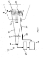
- FIG. 5 is a schematic diagram of a temperature measurement instrument
- the size of the infrared detector 20 may vary.
- the infrared detector 20 has a 320 x 240 pixel array.
- the infrared detector 20 has an array of 160 by 120 pixels.
- the size of the infrared detector 20 may be larger or smaller than these examples. While larger detector arrays can provide greater resolution and more information, smaller detector arrays can provide cost savings while still providing some level of two-dimensional support.
- the infrared detector 20 includes an array having less than 100 x 100 pixels.
- the actuator system 28 moves the light beam 32 to visually identify the selected area 34 of the target 14, for example, by illuminating a portion of the selected area with the light beam 32.
- the light beam 32 may form a dot or spot of light upon the selected area 34, may outline the selected area 34, or otherwise visually identify the selected 32 of the target 14.
- the actuator system 28 and light source/beam, coupled with the infrared detector 20 and processing electronics 24, provide a system and method for visually identifying an area of the target.
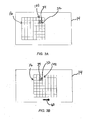
- the temperature measurement instrument 10 can identify portions of the target 14 exhibiting features meeting the set criteria.
- an operator using the temperature measurement instrument 10 can easily correlate temperature measurements with specific portions of the target 14.
- the actuator system 28 moves 58 the light beam 32 to visually identify the selected area 34 on the target 14.
- the actuator system 28 moves the light beam 32 relative to the temperature measurement instrument 10, and thus also relative to the measurement area 16 and the field of view 18 to visually identify different areas of the measurement area 16 meeting the temperature criterion.
- the temperature measurement instrument 10 provides advanced capabilities over temperature measurement instruments that only include a sighting beam always illuminating the same portion of the measurement area.
- embodiments of the invention provide greater versatility than systems such as those with laser beams only for indicating, e.g., the center of the instrument's measurement area, or the outer perimeter of the measurement area.
- the processing electronics 24 and the actuator system 28 cooperate to move the light beam at visually imperceptible frequencies.
- the temperature measurement instrument 10 may perform an iteration of the method of FIG. 2 after a period of only a few milliseconds or microseconds.
- the actuator system 28 employs one or more servo motors to quickly move the light beam 32.
- the actuator system 28 may include one motor for moving the light beam 32 in a vertical or elevation direction, and another motor for moving the light beam 32 in a horizontal or azimuth direction.
- the selected area 34 may include a plurality of noncontiguous discrete areas. For example, several different components on an electrical panel may meet the temperature criterion. In such a case, the selected area 34 may be determined to include all such discrete areas meeting the temperature criterion.
Landscapes
- Physics & Mathematics (AREA)
- General Physics & Mathematics (AREA)
- Spectroscopy & Molecular Physics (AREA)
- Radiation Pyrometers (AREA)
- Photometry And Measurement Of Optical Pulse Characteristics (AREA)
Applications Claiming Priority (1)
| Application Number | Priority Date | Filing Date | Title |
|---|---|---|---|
| US12/354,104 US8167483B2 (en) | 2009-01-15 | 2009-01-15 | Temperature measurement instruments and methods for identifying a selected target area |
Publications (2)
| Publication Number | Publication Date |
|---|---|
| EP2208977A2 true EP2208977A2 (de) | 2010-07-21 |
| EP2208977A3 EP2208977A3 (de) | 2013-01-23 |
Family
ID=42131538
Family Applications (1)
| Application Number | Title | Priority Date | Filing Date |
|---|---|---|---|
| EP09252681A Withdrawn EP2208977A3 (de) | 2009-01-15 | 2009-11-26 | Temperaturmessgeräte und Verfahren zur Identifizierung eines ausgewählten Zielbereichs |
Country Status (3)
| Country | Link |
|---|---|
| US (1) | US8167483B2 (de) |
| EP (1) | EP2208977A3 (de) |
| CN (1) | CN101782434A (de) |
Cited By (3)
| Publication number | Priority date | Publication date | Assignee | Title |
|---|---|---|---|---|
| EP2415973A3 (de) * | 2010-08-05 | 2015-01-14 | General Electric Company | Wärmesteuerungssystem zur Fehlererkennung und -minderung in einem Stromerzeugungssystem |
| EP2415972A3 (de) * | 2010-08-05 | 2015-01-14 | General Electric Company | System und Verfahren zum Messen der Temperatur in einem Turbinensystem |
| US9019108B2 (en) | 2010-08-05 | 2015-04-28 | General Electric Company | Thermal measurement system for fault detection within a power generation system |
Families Citing this family (21)
| Publication number | Priority date | Publication date | Assignee | Title |
|---|---|---|---|---|
| US9674458B2 (en) * | 2009-06-03 | 2017-06-06 | Flir Systems, Inc. | Smart surveillance camera systems and methods |
| US8577183B2 (en) * | 2009-08-05 | 2013-11-05 | Raytheon Company | Resolution on demand |
| US8410946B2 (en) | 2010-03-05 | 2013-04-02 | General Electric Company | Thermal measurement system and method for leak detection |
| US8702372B2 (en) | 2010-05-03 | 2014-04-22 | Bha Altair, Llc | System and method for adjusting compressor inlet fluid temperature |
| CN101936771A (zh) * | 2010-08-02 | 2011-01-05 | 中国科学院长春光学精密机械与物理研究所 | 红外成像测温式能流密度测量装置 |
| US8650883B2 (en) * | 2010-08-11 | 2014-02-18 | General Electric Company | System and method for operating a gas turbine |
| US9305963B2 (en) * | 2011-04-08 | 2016-04-05 | Lasermax, Inc. | Marking system and method |
| US9143703B2 (en) * | 2011-06-10 | 2015-09-22 | Flir Systems, Inc. | Infrared camera calibration techniques |
| WO2013049474A1 (en) * | 2011-09-29 | 2013-04-04 | Covidien Lp | Electronic thermometer with image sensor and display |
| CN103975577B (zh) | 2011-10-07 | 2017-09-19 | 菲力尔系统公司 | 智能监视摄像机系统及方法 |
| TWI485396B (zh) * | 2011-11-24 | 2015-05-21 | Univ Nat Central | 高適應性熱特性量測系統及其方法 |
| US9413988B2 (en) * | 2012-07-24 | 2016-08-09 | Fluke Corporation | Thermal imaging camera with graphical temperature plot |
| US12080406B2 (en) * | 2013-02-25 | 2024-09-03 | Complete Consent, Llc | Tracking and quality assurance of pathology, radiology and other medical or surgical procedures |
| CN103675020B (zh) * | 2013-12-18 | 2016-04-20 | 工业和信息化部电子第五研究所 | 电子组件发射率检测系统 |
| CN105620784A (zh) * | 2014-10-31 | 2016-06-01 | 中国航空工业集团公司西安飞机设计研究所 | 一种飞机风挡加温系统地面测试装置及测试方法 |
| WO2018031910A1 (en) * | 2016-08-12 | 2018-02-15 | Timothy Johnson | Temperature measurement by infrared analysis |
| US11209316B2 (en) | 2016-08-12 | 2021-12-28 | Thermowand Technologies, Inc. | Temperature measurement by infrared analysis |
| US10537394B2 (en) * | 2016-12-19 | 2020-01-21 | Ethicon Llc | Hot device indication of video display |
| US11927488B2 (en) * | 2019-01-03 | 2024-03-12 | Chia-Ling Chen | Thermal detection system capable of providing early warning and related products |
| CN111413008A (zh) * | 2020-04-08 | 2020-07-14 | 达闼机器人有限公司 | 一种温度检测装置、检测方法、电子设备及存储介质 |
| EP3922968A3 (de) | 2020-05-22 | 2022-05-18 | Eaton Intelligent Power Limited | Temperaturmesssystem |
Family Cites Families (33)
| Publication number | Priority date | Publication date | Assignee | Title |
|---|---|---|---|---|
| US4315150A (en) * | 1980-07-24 | 1982-02-09 | Telatemp Corporation | Targeted infrared thermometer |
| US4527896A (en) * | 1982-03-04 | 1985-07-09 | Mikron Instrument Company, Inc. | Infrared transducer-transmitter for non-contact temperature measurement |
| US5011296A (en) * | 1989-01-12 | 1991-04-30 | Square D Company | Method of using infrared thermometer with remote fiber optic pickup |
| US5208528A (en) * | 1989-01-19 | 1993-05-04 | Bull S.A. | Method for inspecting a populated printed circuit board, particularly for inspecting solder joints on the board and a system for working this method |
| FR2665533B1 (fr) | 1990-08-06 | 1994-03-25 | Ortomedic | Dispositif de mesure a distance de temperature et/ou de differences de temperature. |
| US5345304A (en) | 1992-12-17 | 1994-09-06 | Texas Instruments Incorporated | Integrated LADAR/FLIR sensor |
| US5368392B1 (en) | 1993-09-17 | 1998-11-03 | Omega Engineering | Method and apparatus for measuring temperature using infrared techniques |
| US5727880A (en) * | 1993-09-17 | 1998-03-17 | Omega Engineering, Inc. | Method and apparatus for measuring temperature using infrared techniques |
| US5823678A (en) | 1993-09-17 | 1998-10-20 | Omega Engineering, Inc. | Light source aiming system and method for hand-held temperature measuring unit |
| US5626424A (en) | 1994-07-21 | 1997-05-06 | Raytek Subsidiary, Inc. | Dual light source aiming mechanism and improved actuation system for hand-held temperature measuring unit |
| DE19528590C3 (de) | 1995-08-03 | 2003-11-27 | Raytek Gmbh | Vorrichtung zur Temperaturmessung |
| US5710428A (en) * | 1995-08-10 | 1998-01-20 | Samsung Electronics Co., Ltd. | Infrared focal plane array detecting apparatus having light emitting devices and infrared camera adopting the same |
| CA2250751C (en) | 1996-04-01 | 2002-03-12 | Lockheed Martin Corporation | Combined laser/flir optics system |
| US5796474A (en) | 1996-06-21 | 1998-08-18 | Thermotrex Corporation | Projectile tracking system |
| US5836694A (en) | 1996-12-10 | 1998-11-17 | Raytek Subsidiary, Inc. | Laser and scope aiming mechanism for a hand-held temperature measuring unit |
| IL123787A0 (en) * | 1998-03-23 | 1998-10-30 | Veino Med Temed Ltd | Instrument for locating and marking a vein |
| US6606115B1 (en) * | 1998-04-18 | 2003-08-12 | Flir Systems Boston | Method and apparatus for monitoring the thermal characteristics of an image |
| JP3042517B1 (ja) | 1998-11-26 | 2000-05-15 | 日本電気株式会社 | 貯炭山温度計測の方法とその装置 |
| US7365326B2 (en) * | 2000-12-26 | 2008-04-29 | Honeywell International Inc. | Camera having distortion correction |
| WO2002059587A2 (de) * | 2001-01-26 | 2002-08-01 | Rolf Sandvoss | Thermographieverfahren |
| EP1386481A1 (de) | 2001-05-07 | 2004-02-04 | Flir Systems AB | Infrarotstrahlungsempfindliche infrarotkamera |
| WO2003067276A2 (en) | 2002-02-04 | 2003-08-14 | Bae Systems Information And Electronic Systems Integration Inc. | Reentry vehicle interceptor with ir and variable fov laser radar |
| US6836320B2 (en) | 2002-10-23 | 2004-12-28 | Ae Systems Information And Electronic Systems Integration Inc. | Method and apparatus for active boresight correction |
| EP1649256B1 (de) | 2003-07-30 | 2010-01-20 | Optris GmbH | Vorrichtung zur beruhrungslosen temperaturmessung |
| US7611278B2 (en) | 2003-12-02 | 2009-11-03 | White Box, Inc. | Infrared thermometers |
| US7355178B2 (en) * | 2004-06-22 | 2008-04-08 | Everest Charles E | Infrared thermometer with through-the-lens visible targeting system |
| CN101111748B (zh) | 2004-12-03 | 2014-12-17 | 弗卢克公司 | 具有激光指示器的可见光和ir组合的图像照相机 |
| US7457441B2 (en) * | 2005-02-25 | 2008-11-25 | Aptina Imaging Corporation | System and method for detecting thermal anomalies |
| US7332716B2 (en) | 2005-06-06 | 2008-02-19 | Flir Systems Ab | IR camera |
| US7795583B1 (en) * | 2005-10-07 | 2010-09-14 | The United States Of America As Represented By The Secretary Of The Navy | Long range active thermal imaging system and method |
| US7671337B1 (en) * | 2005-11-29 | 2010-03-02 | Lockheed Martin Corporation | System and method for pointing a laser beam |
| US7693679B1 (en) * | 2007-02-08 | 2010-04-06 | Fluke Corporation | System and method for configuring a thermal imaging instrument |
| US7515986B2 (en) * | 2007-04-20 | 2009-04-07 | The Boeing Company | Methods and systems for controlling and adjusting heat distribution over a part bed |
-
2009
- 2009-01-15 US US12/354,104 patent/US8167483B2/en active Active
- 2009-10-30 CN CN200910209042A patent/CN101782434A/zh active Pending
- 2009-11-26 EP EP09252681A patent/EP2208977A3/de not_active Withdrawn
Non-Patent Citations (1)
| Title |
|---|
| None |
Cited By (4)
| Publication number | Priority date | Publication date | Assignee | Title |
|---|---|---|---|---|
| EP2415973A3 (de) * | 2010-08-05 | 2015-01-14 | General Electric Company | Wärmesteuerungssystem zur Fehlererkennung und -minderung in einem Stromerzeugungssystem |
| EP2415972A3 (de) * | 2010-08-05 | 2015-01-14 | General Electric Company | System und Verfahren zum Messen der Temperatur in einem Turbinensystem |
| US9019108B2 (en) | 2010-08-05 | 2015-04-28 | General Electric Company | Thermal measurement system for fault detection within a power generation system |
| US9097182B2 (en) | 2010-08-05 | 2015-08-04 | General Electric Company | Thermal control system for fault detection and mitigation within a power generation system |
Also Published As
| Publication number | Publication date |
|---|---|
| CN101782434A (zh) | 2010-07-21 |
| EP2208977A3 (de) | 2013-01-23 |
| US20100179785A1 (en) | 2010-07-15 |
| US8167483B2 (en) | 2012-05-01 |
Similar Documents
| Publication | Publication Date | Title |
|---|---|---|
| US8167483B2 (en) | Temperature measurement instruments and methods for identifying a selected target area | |
| US20240045042A1 (en) | Methods and Systems for LIDAR Optics Alignment | |
| US20190364227A1 (en) | Visible light and ir combined image camera | |
| US7994480B2 (en) | Visible light and IR combined image camera | |
| CN111149015B (zh) | 同步旋转lidar和卷帘快门相机系统 | |
| US7535002B2 (en) | Camera with visible light and infrared image blending | |
| US7924312B2 (en) | Infrared and visible-light image registration | |
| EP1811771B1 (de) | Kamera mit Bildmischung aus sichtbarem Licht und Infrarotlicht | |
| US6031606A (en) | Process and device for rapid detection of the position of a target marking | |
| US8222602B2 (en) | System for producing enhanced thermal images | |
| EP2608528A1 (de) | Wärmeabbildungskamara für die Infrarotrefotografie | |
| US7164467B2 (en) | Method and apparatus for electronically generating an outline indicating the size of an energy zone imaged onto the IR detector of a radiometer | |
| CN1853092B (zh) | 用于非接触温度测量的装置 | |
| JPH09145320A (ja) | 3次元入力カメラ | |
| RU2584370C2 (ru) | Видеоизмерительное устройство для контроля неровностей внутренней вертикальной цилиндрической поверхности | |
| Johnson et al. | Commercial fusion camera |
Legal Events
| Date | Code | Title | Description |
|---|---|---|---|
| PUAI | Public reference made under article 153(3) epc to a published international application that has entered the european phase |
Free format text: ORIGINAL CODE: 0009012 |
|
| AK | Designated contracting states |
Kind code of ref document: A2 Designated state(s): AT BE BG CH CY CZ DE DK EE ES FI FR GB GR HR HU IE IS IT LI LT LU LV MC MK MT NL NO PL PT RO SE SI SK SM TR |
|
| AX | Request for extension of the european patent |
Extension state: AL BA RS |
|
| PUAL | Search report despatched |
Free format text: ORIGINAL CODE: 0009013 |
|
| AK | Designated contracting states |
Kind code of ref document: A3 Designated state(s): AT BE BG CH CY CZ DE DK EE ES FI FR GB GR HR HU IE IS IT LI LT LU LV MC MK MT NL NO PL PT RO SE SI SK SM TR |
|
| AX | Request for extension of the european patent |
Extension state: AL BA RS |
|
| RIC1 | Information provided on ipc code assigned before grant |
Ipc: G01J 5/42 20060101AFI20121220BHEP Ipc: G01J 5/02 20060101ALI20121220BHEP Ipc: G01J 5/08 20060101ALI20121220BHEP Ipc: G01J 5/00 20060101ALI20121220BHEP |
|
| STAA | Information on the status of an ep patent application or granted ep patent |
Free format text: STATUS: THE APPLICATION IS DEEMED TO BE WITHDRAWN |
|
| 18D | Application deemed to be withdrawn |
Effective date: 20130724 |