EP2208957B1 - Ammunition magazine - Google Patents
Ammunition magazine Download PDFInfo
- Publication number
- EP2208957B1 EP2208957B1 EP09252070A EP09252070A EP2208957B1 EP 2208957 B1 EP2208957 B1 EP 2208957B1 EP 09252070 A EP09252070 A EP 09252070A EP 09252070 A EP09252070 A EP 09252070A EP 2208957 B1 EP2208957 B1 EP 2208957B1
- Authority
- EP
- European Patent Office
- Prior art keywords
- magazine
- follower
- casing
- floor plate
- ridge
- Prior art date
- Legal status (The legal status is an assumption and is not a legal conclusion. Google has not performed a legal analysis and makes no representation as to the accuracy of the status listed.)
- Active
Links
Images







Classifications
-
- F—MECHANICAL ENGINEERING; LIGHTING; HEATING; WEAPONS; BLASTING
- F41—WEAPONS
- F41A—FUNCTIONAL FEATURES OR DETAILS COMMON TO BOTH SMALLARMS AND ORDNANCE, e.g. CANNONS; MOUNTINGS FOR SMALLARMS OR ORDNANCE
- F41A9/00—Feeding or loading of ammunition; Magazines; Guiding means for the extracting of cartridges
- F41A9/61—Magazines
- F41A9/62—Magazines having means for indicating the number of cartridges left in the magazine, e.g. last-round indicators
-
- F—MECHANICAL ENGINEERING; LIGHTING; HEATING; WEAPONS; BLASTING
- F41—WEAPONS
- F41A—FUNCTIONAL FEATURES OR DETAILS COMMON TO BOTH SMALLARMS AND ORDNANCE, e.g. CANNONS; MOUNTINGS FOR SMALLARMS OR ORDNANCE
- F41A9/00—Feeding or loading of ammunition; Magazines; Guiding means for the extracting of cartridges
- F41A9/61—Magazines
- F41A9/64—Magazines for unbelted ammunition
- F41A9/65—Box magazines having a cartridge follower
- F41A9/69—Box magazines having a cartridge follower characterised by multiple-row or zigzag arrangement of cartridges
-
- F—MECHANICAL ENGINEERING; LIGHTING; HEATING; WEAPONS; BLASTING
- F41—WEAPONS
- F41A—FUNCTIONAL FEATURES OR DETAILS COMMON TO BOTH SMALLARMS AND ORDNANCE, e.g. CANNONS; MOUNTINGS FOR SMALLARMS OR ORDNANCE
- F41A9/00—Feeding or loading of ammunition; Magazines; Guiding means for the extracting of cartridges
- F41A9/61—Magazines
- F41A9/64—Magazines for unbelted ammunition
- F41A9/65—Box magazines having a cartridge follower
-
- F—MECHANICAL ENGINEERING; LIGHTING; HEATING; WEAPONS; BLASTING
- F41—WEAPONS
- F41A—FUNCTIONAL FEATURES OR DETAILS COMMON TO BOTH SMALLARMS AND ORDNANCE, e.g. CANNONS; MOUNTINGS FOR SMALLARMS OR ORDNANCE
- F41A9/00—Feeding or loading of ammunition; Magazines; Guiding means for the extracting of cartridges
- F41A9/61—Magazines
- F41A9/64—Magazines for unbelted ammunition
- F41A9/65—Box magazines having a cartridge follower
- F41A9/70—Arrangements thereon for discharging, e.g. cartridge followers or discharge throats
-
- F—MECHANICAL ENGINEERING; LIGHTING; HEATING; WEAPONS; BLASTING
- F41—WEAPONS
- F41A—FUNCTIONAL FEATURES OR DETAILS COMMON TO BOTH SMALLARMS AND ORDNANCE, e.g. CANNONS; MOUNTINGS FOR SMALLARMS OR ORDNANCE
- F41A9/00—Feeding or loading of ammunition; Magazines; Guiding means for the extracting of cartridges
- F41A9/82—Reloading or unloading of magazines
- F41A9/83—Apparatus or tools for reloading magazines with unbelted ammunition, e.g. cartridge clips
Definitions
- the present invention relates to an ammunition magazine.
- Embodiments of the present invention relate to the field of firearms and more particularly to an improved ammunition magazine.
- Ammunition magazines are well known in the art of firearms. Their basic construction is a containment shell, "casing” or “body” with two open ends. One end is deemed the “floor” of the magazine and is covered by a plate while the opposite end is the “feed” end and interfaces with the weapon.
- a spring and follower assembly Inside the volume defined by the casing and plate is a spring and follower assembly. When ammunition is loaded into the magazine, the ammunition pushes the follower down towards the floor and thereby compresses the spring. In use, when one cartridge of ammunition is expended, the compressed spring releases and pushes the follower and associated ammunition upwards toward the feed end and the next round of ammunition is thereby readied.
- Prior magazines have been manufactured in many different configurations and of different materials. Perhaps the best known in the U.S. are the AK-47 and the USGI AR 15/M 16 magazines. These magazines function similarly, though they are made with slight variations to interface with their host system. Of notable difference is that the AK-47 magazine has a relatively constant curvature while the AR 15/M 16 magazine has a less curved lower region that gradually resolves to a more linear function towards the feed end. Both use the same type of internal system. Of particular note with both, and all follower magazine systems, is that the system works well only as the follower smoothly and levelly travels the inside of the magazine. As the follower must move, there is room for the follower in all the known prior art magazines to move axially, or "wobble" and possibly jam. This is notorious in the AR15/M16 magazine style as the geometry of the magazine is inherently not uniform.
- DE 32 08 504 A1 describes an ammunition magazine comprising a cylindrical casing having a mostly rectangular cross-section and first and second open ends, a follower residing within the casing, said follower comprising a follower platform with two opposite tines extending towards the second end and generally perpendicularly and distally therefrom; a floor plate capable of interfacing the magazine at the second end; and a follower spring residing between the follower and the floor plate; wherein the tines limit rotation of the follower with the casing.
- Embodiments of the present invention provide a polymer magazine with angularly shaped guide rails to interface with the internal follower, thereby restricting axial motion of the follower.
- the magazine also features a load indicator and a two-piece floor plate locking system.
- Embodiments of the present invention represents a departure from the prior art in that the magazine of embodiments of the present invention allows for more stable and level motion of the follower while the magazine is loaded or unloaded.
- embodiments of this invention provide an improved magazine.
- embodiments of the present invention's general purpose is to provide a new and improved magazine that is backwards compatible with known weapon platforms and presents a more stable follower and follower path.
- the improved ammunition magazine according to claim 1 comprises two lateral angularly shaped guide rails and ridge within the magazine casing and a follower that is configured to abut them.
- the magazine may also feature a polymer construction and an ammunition load indicator system.
- the magazine may also feature a cover for storage.
- the magazine further comprises at least one window in the casing, through which the spring is viewable.
- the magazine further comprises a rim about the second end and the floor plate being capable of a sliding relationship over said rim.
- the floor plate further comprises an interior locking plate with tab and an exterior floor plate with a mating slot and a ledge capable of interfacing with the rim, the interior locking plate also having a support ridge extending therefrom on a side opposite the tab.
- the magazine further comprises a tab, projecting internally from the ridge terminus and a detent, situated in the follower platform to interface with tab, thereby preventing the follower from exiting the magazine through the first end.
- the magazine further comprises a rim about the second end and the floor plate being capable of a sliding relationship over said rim.
- the floor plate further comprises an interior locking plate with a tab and an exterior floor plate with a mating slot and a ledge capable of interfacing with the rim.
- the magazine 1 generally comprises a casing 10 having a floor end 13 and a feed end 17. Feed lips 21 are provided at the feed end 17 to interface with a weapon and to guide cartridges into the firing chamber of said weapon.
- the floor end is capped with a floor plate 20 which is secured by a lock plate 25.
- a spring 35 rests against the lock plate 25, centered by walls 24, and floor plate 20 combination and provides tension to bias the follower 30 and the floor plate 20 so that the follower 30 will progress up the magazine casing 10 as ammunition is used.
- Floor plate 20 slides over a rim 23 of the floor end 13, using a ledge to interface with the rim, and simultaneously over the lock plate 25.
- Magazine 1 also features two indicator windows 15 to view the spring.
- An indicator which could be as simple as a colored dot or a dab of properly placed paint, is positioned on the spring and is viewable through the windows when the magazine 1 is assembled.
- the windows 15 are positioned on either side of the magazine casing 10 and are close enough to the floor end so that they are not obscured when the magazine 1 is inserted in a weapon's magazine well.
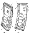
- Figures 2-4 provide views of the magazine 1 assembled, Fig. 4 without the impact cover 40.
- the ridge serves three purposes. The first purpose is to provide additional stability and strength to the magazine casing 10. The second purpose is to divide tips of cartridges, left from right, in their off-set stacking in the magazine. The third purpose is to provide an additional interface with the follower 30 to prevent forward linear and axial tilt.
- the ridge 19 may terminate at a point significantly below the feed lips, about .5 inches for a .223 caliber magazine, as shown in FIGS. 19-22 .
- the casing also has two lateral guide rails 31 extending through the casing 10.
- the guide rails 31 are flattened in front and angular towards the rear so as to present a more solid surface for the follower to abut and to guide cartridges as they travel through the magazine casing 10. So as to not interfere with feeding of cartridges in to the weapon, the guide rails 31 should terminate 31 a at approximately a cartridge's diameter of the feed end 17 of the magazine casing (as defined by the level where the rib 19 terminates with tab 29), or within 1 ⁇ 4 inch for a .223 magazine. This is, however, only for the preferred embodiment, as the guide rails 31 can extend the entire length of the magazine casing 10 and the magazine will still be functional, just not preferred.
- the follower 30 has two tines, a forward tine 33 and hind tine 37. Both tines are elongated and extending from platform 34.
- the forward tine 33 presses against the ridge 19 and prevents axial movement, particularly those movements caused by the simple act of firing the weapon, which would push the rear of the ammunition (and the follower 30) down.
- the hind tine 37 fits into trough 11 ( FIG. 7 ) to prevent lateral movement.
- the extension of the tines greatly inhibit axial and lateral movement as the extension increases contact with the magazine casing and provide more counter-torque when forces would cause such movement.
- the follower also has two lateral arms 36 that fit alongside of the lateral fins 31 to further inhibit rotation.
- the follower 30 interfaces with spring 35 by attachment of the spring 35 to loop 38 and retention of the spring 35 by retaining wall 32.
- ridge 19 At the top of ridge 19 is a slight tab 29 ( FIGS. 6 and 8 ) that protrudes towards the interior of the magazine 1.
- Tab 29 serves as a block to prevent the follower 30 from exiting the feed end 17 of the magazine 1. It interfaces with a detent 39 provided in the follower 30 ( FIGS. 9, 9b, and 9e ). In the embodiment shown in FIGS. 19-22 , the tab 29 is, of course, lower in relation to the feed lips.
- the follower 30 then, as shown in FIGS. 23-31 has a chamfered groove 90 so as to allow the follower 30 to still be blocked, but in a manner that allows it to fully rise in relation to the magazine.
- the groove 90 also allows further interface to reduce disadvantageous tilt in the follower.
- Lock plate 25 may also feature a ridge 96 to interface with the bottom of the follower 30 when the magazine is fully loaded, so as to support the follower 30 and round stack and reduce spring fatigue, as shown in FIGS. 19 - 22 .
- the magazine casing is comprised of a glass-reinforced thermoplastic polymer selected to resist the heat generated from firing a rifle.
- a glass-reinforced thermoplastic polymer selected to resist the heat generated from firing a rifle.
- other polymers like polycarbonate, may be used and the magazines may be made in any color or opacity (which can reduce or eliminate the need for a magazine level indicator).
- Some polymers, such as polycarbonate, may be used without reinforcement.
- Other reinforcement materials such as steel, carbon fiber, or other materials may also be used to reinforce the magazine.
- the magazine casing may be made of other materials having suitable strength and durability, such as titanium, ceramics, laminates, amorphous metals, etc.
- the follower is preferred to be made of polyoxymethylene, acetal resin available commercially from DuPont under the trade name DELRIN®, though other materials are suitable, just not preferred.
- the magazine 1 is structured to increase its structural integrity. To that end, fore ridge 19 provides added durability to the magazine.
- Protective cover 40 also provides reinforcement during storage, as pressures from the stored ammunition and spring 35 would normally force the feed lips 21 of the magazine 1 apart.
- Protective cover 40 shown in FIGS. 10-10e , interfaces with geometry, namely notch 44 and hinge base 48, on the magazine casing 10 with latch 43 and cover hinge 47 ( FIGS. 2, 3 and 4 ), and forces the ammunition downward with an underside spacer 45, thereby absorbing and distributing the forces that would normally be applied to the feed lips 21 in a more advantageous manner.
- Geometry 92 may be added to the magazine to allow the cover to fasten on the bottom of the magazine for storage as well ( FIGS. 13-18 ).
- a double notch 94 may be utilized ( FIG. 17 ) as this geometry can benefit the molding process.
- the cover 40 also serves as a magazine tool as the cover latch 43 will fit between the feed lips 21 so as to push rounds of ammunition 50 out of the magazine 1 ( FIGS. 11a - 11c ). It also has a specialized gauge 49 to determine if the feed lips 21 have either splayed or compressed in a manner to prevent operability of the magazine with the weapon. Gauge 49 is a flared area, specially sized depending upon the size of ammunition, slightly above latch 43. The operable magazine 1 will accommodate the latch 43 between the feed lips 21, but not the gauge. If the latch 43 is unable to fit between feed lips 21, then the feed lips 21 have compressed in some manner, perhaps due to impact or compression damage, and the magazine 1 is then not fit for use.
- gauge 49 is able to fit between feed lips 21, then the feed lips 21 have splayed, perhaps due to long term storage without the impact cover 40, and the magazine 1 is not fit for use. Measurements of the gauge and latch widths will be dependent upon the type of ammunition used. Likewise, this magazine 1 is capable of being used in multiple weapon platforms, each with its own tolerances. The widths of the latch 43 and gauge 49 would be dependent upon those tolerances and different weapon platforms may be accommodated my merely fashioning a different version of the impact cover 40 for that platform, without changing the magazine as a whole. Impact cover 40 may also be used to depress the locking plate tab 26 so as to remove the floor plate 20 ( FIGS. 12a - 12c ).
- magazine casing 10 presents a constant internal curve, with slight straightening near the interior rear face of the feed lips only to allow interface with a weapon. As such, the follower 30 and associated ammunition travel more smoothly through the magazine casing 10 with lessened round stack variation.
- Embodiments provide an ammunition magazine, preferably made of a glass fiber reinforced polymer, utilising a structurally enhancing ridge, optionally together with angular guide rails and a follower made to interface with said guide rails to reduce wobble.
- the preferred embodiment may also feature a protective cover that distributes forces from the spring to more structurally sound areas of the magazine, thus reducing feed end splay, together optionally with an ammunition indication system comprised of at least one window and a noticeable marker on the follower spring.
- the follower and magazine casing may be designed to interface to prevent the follower from popping out of the feed end and the floor plate of the magazine may optionally utilize a locking plate and sliding relationship between the floor plate, locking plate and magazine to secure the floor plate onto the magazine casing.
- the cover may optionally feature built in tools for, among other things, unloading and disassembling the magazine.
Landscapes
- Engineering & Computer Science (AREA)
- General Engineering & Computer Science (AREA)
- Portable Nailing Machines And Staplers (AREA)
Description
- The present invention relates to an ammunition magazine. Embodiments of the present invention relate to the field of firearms and more particularly to an improved ammunition magazine.
- Ammunition magazines are well known in the art of firearms. Their basic construction is a containment shell, "casing" or "body" with two open ends. One end is deemed the "floor" of the magazine and is covered by a plate while the opposite end is the "feed" end and interfaces with the weapon. Inside the volume defined by the casing and plate is a spring and follower assembly. When ammunition is loaded into the magazine, the ammunition pushes the follower down towards the floor and thereby compresses the spring. In use, when one cartridge of ammunition is expended, the compressed spring releases and pushes the follower and associated ammunition upwards toward the feed end and the next round of ammunition is thereby readied.
- Prior magazines have been manufactured in many different configurations and of different materials. Perhaps the best known in the U.S. are the AK-47 and the USGI AR 15/M 16 magazines. These magazines function similarly, though they are made with slight variations to interface with their host system. Of notable difference is that the AK-47 magazine has a relatively constant curvature while the AR 15/M 16 magazine has a less curved lower region that gradually resolves to a more linear function towards the feed end. Both use the same type of internal system. Of particular note with both, and all follower magazine systems, is that the system works well only as the follower smoothly and levelly travels the inside of the magazine. As the follower must move, there is room for the follower in all the known prior art magazines to move axially, or "wobble" and possibly jam. This is notorious in the AR15/M16 magazine style as the geometry of the magazine is inherently not uniform.
-
DE 32 08 504 A1 describes an ammunition magazine comprising a cylindrical casing having a mostly rectangular cross-section and first and second open ends, a follower residing within the casing, said follower comprising a follower platform with two opposite tines extending towards the second end and generally perpendicularly and distally therefrom; a floor plate capable of interfacing the magazine at the second end; and a follower spring residing between the follower and the floor plate; wherein the tines limit rotation of the follower with the casing. - Embodiments of the present invention provide a polymer magazine with angularly shaped guide rails to interface with the internal follower, thereby restricting axial motion of the follower. The magazine also features a load indicator and a two-piece floor plate locking system. Embodiments of the present invention represents a departure from the prior art in that the magazine of embodiments of the present invention allows for more stable and level motion of the follower while the magazine is loaded or unloaded.
- In view of the foregoing disadvantages inherent in the known types of ammunition magazines, embodiments of this invention provide an improved magazine. As such, embodiments of the present invention's general purpose is to provide a new and improved magazine that is backwards compatible with known weapon platforms and presents a more stable follower and follower path.
- To accomplish these objectives, the improved ammunition magazine according to
claim 1 comprises two lateral angularly shaped guide rails and ridge within the magazine casing and a follower that is configured to abut them. By interfacing with more internal structure, all non-advantageous linear and axial motion is inhibited and the follower is then more stable in its progress. The magazine may also feature a polymer construction and an ammunition load indicator system. The magazine may also feature a cover for storage. - According to the invention, there is provided an ammunition magazine as claimed in
Claim 1. - Further particular and preferred aspects of the present invention are set out in the accompanying independent and dependent claims. Features of the dependent claims may be combined with features of the independent claims as appropriate.
- In embodiments, the magazine further comprises at least one window in the casing, through which the spring is viewable.
- In embodiments, the magazine further comprises a rim about the second end and the floor plate being capable of a sliding relationship over said rim.
- In embodiments, the floor plate further comprises an interior locking plate with tab and an exterior floor plate with a mating slot and a ledge capable of interfacing with the rim, the interior locking plate also having a support ridge extending therefrom on a side opposite the tab.
- In embodiments, the magazine further comprises a tab, projecting internally from the ridge terminus and a detent, situated in the follower platform to interface with tab, thereby preventing the follower from exiting the magazine through the first end.
- In embodiments, the magazine further comprises a rim about the second end and the floor plate being capable of a sliding relationship over said rim.
- In embodiments, the floor plate further comprises an interior locking plate with a tab and an exterior floor plate with a mating slot and a ledge capable of interfacing with the rim.
- The more important features of embodiments of the invention have thus been outlined in order that the more detailed description that follows may be better understood and in order that the present contribution to the art may better be appreciated. Additional features of embodiments of the invention will be described hereinafter and will form the subject matter of the claims that follow.
- Many objects of embodiments of this invention will appear from the following description and appended claims, reference being made to the accompanying drawings forming a part of this specification wherein like reference characters designate corresponding parts in the several views.
- Before explaining at least one embodiment of the invention in detail, it is to be understood that the invention is not limited in its application to the details of construction and the arrangements of the components set forth in the following description or illustrated in the drawings. The invention as defined in the claims may be embodied in other ways. Also it is to be understood that the phraseology and terminology employed herein are for the purpose of description and should not be regarded as limiting.
- As such, those skilled in the art will appreciate that the conception, upon which this disclosure is based, may readily be utilized as a basis for the designing of other structures, methods and systems for carrying out the several purposes of the present invention. It is important, therefore, that the claims be regarded as including such equivalent constructions insofar as they do not depart from the scope of the present invention as set out in the claims.
- The present invention will be described further, by way of example only, with reference to preferred embodiments thereof as illustrated in the accompanying drawings, in which:
-
Figure 1 is an exploded view of the magazine according to an embodiment of the present invention. -
Figure 2 is a perspective view of the assembled magazine according to an embodiment of the present invention. -
Figure 3 is a side plan view of the magazine ofFIG. 2 . -
Figure 4 is a perspective view of the magazine according to an embodiment of the present invention, without the impact cover. -
Figure 5 is a hind plan view of the magazine ofFIG. 4 . -
Figure 6 is a sectional view of the magazine inFIG. 5 , taken along line 6-6. -
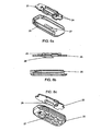
Figure 6a is a perspective view of the floor and lock plates according to an embodiment of the present invention. -
Figure 6b is a side plan view of the floor and lock plates ofFIG. 6a . -
Figure 6c is an alternative perspective view of the floor and lock plates ofFIG. 6a . -
Figure 7 is a bottom plan view of the magazine casing, according to an embodiment of the present invention. -
Figure 8 is a cross-section of the magazine casing ofFIG. 7 , taken along line 8-8 and re-orientated with the bottom down. -
Figure 9 is a perspective view of the follower according to an embodiment of the present invention. -
Figure 9a is a side plan view of the follower ofFIG. 9 . -
Figure 9b is a front plan view of the follower ofFIG. 9 . -
Figure 9c is a rear plan view of the follower ofFIG. 9 . -
Figure 9d is a bottom plan view of the follower ofFIG. 9 . -
Figure 9e is a sectional view of the follower ofFIG. 9d , taken alongline 9e-9e. -
Figure 10 is a perspective view of the impact cover according to an embodiment of the present invention. -
Figure 10a is a side plan view of the impact cover ofFIG. 10 . -
Figure 10b is a front plan view of the impact cover ofFIG. 10 . -
Figure 10c is a rear plan view of the impact cover ofFIG. 10 . -
Figure 10d is a bottom plan view of the impact cover ofFIG. 10 . -
Figure 10e is a sectional view of the impact ofFIG. 10d , taken alongline 10e-10e. -
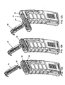
Figures 11a - 11c are successive plan views showing use of the impact cover as a magazine unloading tool. -
Figures 12a - 12c are successive plan views showing use of the impact cover to disassemble the magazine. -
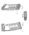
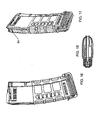
Figure 13 is a side plan view of an alternate embodiment of the magazine according to the present invention. -
Figure 14 is a rear perspective view of the magazine ofFIG. 13 . -
Figure 15 is a bottom plan view of the magazine ofFIG. 13 . -
Figure 16 is a side plan view of the magazine ofFIG. 13 , with the impact cover in a stowed position on the magazine. -
Figure 17 is a rear perspective view of the magazine ofFIG. 16 . -
Figure 18 is a bottom plan view of the magazine ofFIG. 16 . -
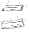
Figure 19 is a sectional view of the magazine ofFIG. 16 . -
Figure 20 is a sectional view of the magazine ofFIG. 17 . -
Figure 21 is a sectional view of the magazine's external components, along the same section line asFIG. 19 . -
Figure 22 is a sectional view of the magazine's external components, along the same section line asFIG. 20 . -
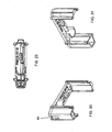
Figure 23 is a left, front, top perspective view of a follower for the alternative magazine embodiment depicted inFIG. 13 . -
Figure 24 is a left, rear, top perspective view of the follower ofFIG. 23 . -
Figure 25 is a top plan view of the follower ofFIG. 23 . -
Figure 26 a left plan view of the follower ofFIG. 23 . -
Figure 27 is a front plan view of the follower ofFIG. 23 . -
Figure 28 is a rear plan view of the follower ofFIG. 23 . -
Figure 29 is a bottom plan view of the follower ofFIG. 23 . -
Figure 30 is a left, front, bottom perspective view of the follower ofFIG. 23 . -
Figure 31 is a left, rear, bottom perspective view of the follower ofFIG. 23 . - With reference now to the drawings, the preferred embodiment of the ammunition magazine is herein described. It should be noted that the articles "a", "an" and "the", as used in this specification, include plural referents unless the content clearly dictates otherwise.
- With reference to
FIG. 1 , themagazine 1 generally comprises acasing 10 having afloor end 13 and afeed end 17. Feedlips 21 are provided at thefeed end 17 to interface with a weapon and to guide cartridges into the firing chamber of said weapon. The floor end is capped with afloor plate 20 which is secured by alock plate 25. Aspring 35 rests against thelock plate 25, centered bywalls 24, andfloor plate 20 combination and provides tension to bias thefollower 30 and thefloor plate 20 so that thefollower 30 will progress up themagazine casing 10 as ammunition is used.Floor plate 20 slides over arim 23 of thefloor end 13, using a ledge to interface with the rim, and simultaneously over thelock plate 25. Thefloor plate 20 andlock plate 25 interface together with atab 26 on the lock plate resting within aslot 27 of the floor plate (shown inFIGS. 6-6c ), so, with thefloor plate 20 holding themagazine 1 and thelock plate 25 holding thefloor plate 20 laterally, as it is forced against thefloor plate 20 by the spring, thefloor plate 20 does not slide off themagazine 1. Aprotective impact cover 40 is also provided for use during storage.Magazine 1 also features twoindicator windows 15 to view the spring. An indicator, which could be as simple as a colored dot or a dab of properly placed paint, is positioned on the spring and is viewable through the windows when themagazine 1 is assembled. Ideally, thewindows 15 are positioned on either side of themagazine casing 10 and are close enough to the floor end so that they are not obscured when themagazine 1 is inserted in a weapon's magazine well.
Figures 2-4 provide views of themagazine 1 assembled,Fig. 4 without theimpact cover 40. - Inside the
casing 10, along the fore side of themagazine 1, is aridge 19, shown inFIGS. 6 ,7, and 8 . The ridge serves three purposes. The first purpose is to provide additional stability and strength to themagazine casing 10. The second purpose is to divide tips of cartridges, left from right, in their off-set stacking in the magazine. The third purpose is to provide an additional interface with thefollower 30 to prevent forward linear and axial tilt. In order to accommodate stripper clips, theridge 19 may terminate at a point significantly below the feed lips, about .5 inches for a .223 caliber magazine, as shown inFIGS. 19-22 . The casing also has twolateral guide rails 31 extending through thecasing 10. The guide rails 31 are flattened in front and angular towards the rear so as to present a more solid surface for the follower to abut and to guide cartridges as they travel through themagazine casing 10. So as to not interfere with feeding of cartridges in to the weapon, the guide rails 31 should terminate 31 a at approximately a cartridge's diameter of thefeed end 17 of the magazine casing (as defined by the level where therib 19 terminates with tab 29), or within ¼ inch for a .223 magazine. This is, however, only for the preferred embodiment, as the guide rails 31 can extend the entire length of themagazine casing 10 and the magazine will still be functional, just not preferred. - As shown in
FIGS. 9 - 9e , thefollower 30 has two tines, aforward tine 33 andhind tine 37. Both tines are elongated and extending fromplatform 34. Theforward tine 33 presses against theridge 19 and prevents axial movement, particularly those movements caused by the simple act of firing the weapon, which would push the rear of the ammunition (and the follower 30) down. Thehind tine 37 fits into trough 11 (FIG. 7 ) to prevent lateral movement. The extension of the tines greatly inhibit axial and lateral movement as the extension increases contact with the magazine casing and provide more counter-torque when forces would cause such movement. The follower also has twolateral arms 36 that fit alongside of thelateral fins 31 to further inhibit rotation. Thefollower 30 interfaces withspring 35 by attachment of thespring 35 toloop 38 and retention of thespring 35 by retainingwall 32. - At the top of
ridge 19 is a slight tab 29 (FIGS. 6 and8 ) that protrudes towards the interior of themagazine 1.Tab 29 serves as a block to prevent thefollower 30 from exiting thefeed end 17 of themagazine 1. It interfaces with adetent 39 provided in the follower 30 (FIGS. 9, 9b, and 9e ). In the embodiment shown inFIGS. 19-22 , thetab 29 is, of course, lower in relation to the feed lips. Thefollower 30 then, as shown inFIGS. 23-31 has a chamferedgroove 90 so as to allow thefollower 30 to still be blocked, but in a manner that allows it to fully rise in relation to the magazine. Thegroove 90 also allows further interface to reduce disadvantageous tilt in the follower.Lock plate 25 may also feature aridge 96 to interface with the bottom of thefollower 30 when the magazine is fully loaded, so as to support thefollower 30 and round stack and reduce spring fatigue, as shown inFIGS. 19 - 22 . - In the preferred embodiment, the magazine casing is comprised of a glass-reinforced thermoplastic polymer selected to resist the heat generated from firing a rifle. However, other polymers, like polycarbonate, may be used and the magazines may be made in any color or opacity (which can reduce or eliminate the need for a magazine level indicator). Some polymers, such as polycarbonate, may be used without reinforcement. Other reinforcement materials, such as steel, carbon fiber, or other materials may also be used to reinforce the magazine. Likewise, the magazine casing may be made of other materials having suitable strength and durability, such as titanium, ceramics, laminates, amorphous metals, etc. The follower is preferred to be made of polyoxymethylene, acetal resin available commercially from DuPont under the trade name DELRIN®, though other materials are suitable, just not preferred.
- The
magazine 1 is structured to increase its structural integrity. To that end,fore ridge 19 provides added durability to the magazine.Protective cover 40 also provides reinforcement during storage, as pressures from the stored ammunition andspring 35 would normally force thefeed lips 21 of themagazine 1 apart.Protective cover 40, shown inFIGS. 10-10e , interfaces with geometry, namely notch 44 and hingebase 48, on the magazine casing 10 withlatch 43 and cover hinge 47 (FIGS. 2, 3 and4 ), and forces the ammunition downward with anunderside spacer 45, thereby absorbing and distributing the forces that would normally be applied to thefeed lips 21 in a more advantageous manner.Geometry 92 may be added to the magazine to allow the cover to fasten on the bottom of the magazine for storage as well (FIGS. 13-18 ). Adouble notch 94 may be utilized (FIG. 17 ) as this geometry can benefit the molding process. - The
cover 40 also serves as a magazine tool as thecover latch 43 will fit between thefeed lips 21 so as to push rounds ofammunition 50 out of the magazine 1 (FIGS. 11a - 11c ). It also has aspecialized gauge 49 to determine if thefeed lips 21 have either splayed or compressed in a manner to prevent operability of the magazine with the weapon.Gauge 49 is a flared area, specially sized depending upon the size of ammunition, slightly abovelatch 43. Theoperable magazine 1 will accommodate thelatch 43 between thefeed lips 21, but not the gauge. If thelatch 43 is unable to fit betweenfeed lips 21, then thefeed lips 21 have compressed in some manner, perhaps due to impact or compression damage, and themagazine 1 is then not fit for use. If thegauge 49 is able to fit betweenfeed lips 21, then thefeed lips 21 have splayed, perhaps due to long term storage without theimpact cover 40, and themagazine 1 is not fit for use. Measurements of the gauge and latch widths will be dependent upon the type of ammunition used. Likewise, thismagazine 1 is capable of being used in multiple weapon platforms, each with its own tolerances. The widths of thelatch 43 andgauge 49 would be dependent upon those tolerances and different weapon platforms may be accommodated my merely fashioning a different version of theimpact cover 40 for that platform, without changing the magazine as a whole.Impact cover 40 may also be used to depress thelocking plate tab 26 so as to remove the floor plate 20 (FIGS. 12a - 12c ). - It should also be noted that magazine casing 10 presents a constant internal curve, with slight straightening near the interior rear face of the feed lips only to allow interface with a weapon. As such, the
follower 30 and associated ammunition travel more smoothly through the magazine casing 10 with lessened round stack variation. - Embodiments provide an ammunition magazine, preferably made of a glass fiber reinforced polymer, utilising a structurally enhancing ridge, optionally together with angular guide rails and a follower made to interface with said guide rails to reduce wobble. The preferred embodiment may also feature a protective cover that distributes forces from the spring to more structurally sound areas of the magazine, thus reducing feed end splay, together optionally with an ammunition indication system comprised of at least one window and a noticeable marker on the follower spring. The follower and magazine casing may be designed to interface to prevent the follower from popping out of the feed end and the floor plate of the magazine may optionally utilize a locking plate and sliding relationship between the floor plate, locking plate and magazine to secure the floor plate onto the magazine casing. The cover may optionally feature built in tools for, among other things, unloading and disassembling the magazine.
- Although illustrative embodiments of the invention have been disclosed in detail herein, with reference to the accompanying drawings, it is understood that the invention is not limited to the precise embodiment and that various changes and modifications can be effected therein by one skilled in the art without departing from the scope of the invention as defined by the appended claims.
Claims (9)
- An ammunition magazine (1) comprising:a cylindrical casing (10) having a mostly rectangular internal cross-section with opposing fore and rear sides joined by a pair of opposing side walls and first (17) and second (13) open ends, the casing further comprising on its inside two guide rails (31), each situated along a respective one of said side walls of the casing, the guide rails each extending inwardly from a respective one of said side walls and presenting an angular cross-section throughout and extending at least mostly along a length of the magazine, from the first open end to the second open end and the casing also comprising on its inside a forward and centrally located ridge (19) extending along said fore side to a terminus (29) located towards the first open end;a follower residing within the casing, said follower further comprising:a follower platform (30) with two opposite tines (33, 37) extending towards the second end and generally perpendicularly anddistally from said follower platform, each tine being located adjacent a respective fore and rear side;two side fins (36) situated to interface with the casing's guide rails;means for interfacing with the said ridge;a floor plate (20, 25) capable of interfacing the casing at the second end; anda follower spring (35) residing between the follower and floor plate;
wherein the tines, the means for interfacing with the said ridge and the side fins limit rotation of the follower within the casing. - The magazine of claim 1, further comprising a protective cover (40) and interfacing geometry on the casing with which to secure the protective cover, the protective cover capable of forcing the follower downward and absorbing at least some pressure applied to the magazine by the spring.
- The magazine of claim 1 or 2, further comprising a constant internal curve through a majority of the length of the magazine.
- The magazine of claim 3, the magazine further comprising a rim (23) about the second end and the floor plate being capable of a sliding relationship over said rim.
- The magazine of claim 4, the floor plate further comprising an interior locking plate (25) with a tab (24) and an exterior floor plate (20) with a mating slot (27) and a ledge capable of interfacing with the rim, the interior locking plate also having a support ridge extending therefrom on a side opposite the tab.
- The magazine of any one of claims 1 or 4 or 5, further comprising a tab, projecting internally from the ridge terminus and a detent, situated in the follower platform to interface with tab, thereby preventing the follower from exiting the magazine through the first end.
- The magazine of claim 6, the magazine casing being made from a fiber-reinforced polymer.
- The magazine of claim 2, the protective cover further comprising at least one tool portion.
- The magazine of claim 8, the at least one tool portion being at least one tool selected from the set of magazine tools consisting of: a magazine unloading tool, a magazine disassembly tool, and a feed lip width gauge.
Priority Applications (1)
| Application Number | Priority Date | Filing Date | Title |
|---|---|---|---|
| PL09252070T PL2208957T3 (en) | 2009-01-15 | 2009-08-26 | Ammunition magazine |
Applications Claiming Priority (1)
| Application Number | Priority Date | Filing Date | Title |
|---|---|---|---|
| US12/354,766 US8069601B1 (en) | 2007-12-17 | 2009-01-15 | Ammunition magazine |
Publications (3)
| Publication Number | Publication Date |
|---|---|
| EP2208957A2 EP2208957A2 (en) | 2010-07-21 |
| EP2208957A3 EP2208957A3 (en) | 2011-09-28 |
| EP2208957B1 true EP2208957B1 (en) | 2013-04-03 |
Family
ID=41129269
Family Applications (1)
| Application Number | Title | Priority Date | Filing Date |
|---|---|---|---|
| EP09252070A Active EP2208957B1 (en) | 2009-01-15 | 2009-08-26 | Ammunition magazine |
Country Status (5)
| Country | Link |
|---|---|
| US (3) | US8069601B1 (en) |
| EP (1) | EP2208957B1 (en) |
| DK (1) | DK2208957T3 (en) |
| ES (1) | ES2418158T3 (en) |
| PL (1) | PL2208957T3 (en) |
Cited By (2)
| Publication number | Priority date | Publication date | Assignee | Title |
|---|---|---|---|---|
| US9222739B1 (en) | 2015-01-29 | 2015-12-29 | Magpul Industries Corp. | Follower and methods for weapons magazine |
| USD844735S1 (en) | 2017-03-07 | 2019-04-02 | Magpul Industries Corp. | Firearm stock |
Families Citing this family (88)
| Publication number | Priority date | Publication date | Assignee | Title |
|---|---|---|---|---|
| US8991086B2 (en) | 2007-06-01 | 2015-03-31 | Magpul Industries Corp. | Ammunition magazine |
| USRE50303E1 (en) | 2007-06-01 | 2025-02-18 | Magpul Industries Corp. | Ammunition magazine |
| US8225541B2 (en) * | 2010-01-12 | 2012-07-24 | Okay Industries, Inc. | Magazine for a firearm |
| US8234810B2 (en) * | 2010-08-08 | 2012-08-07 | Lee Tactical Solutions, L.L.C. | Apparatus and method for loading bullets into a bullet carrier of a magazine |
| USD672837S1 (en) * | 2011-09-01 | 2012-12-18 | Wyatt Kevin R | Rifle magazine |
| US20130074393A1 (en) * | 2011-09-23 | 2013-03-28 | Warren Scott Curry | Magazine disassembly tool |
| USRE49104E1 (en) | 2011-11-30 | 2022-06-14 | Magpul Industries Corp. | Ammunition magazine |
| USD688766S1 (en) | 2012-01-13 | 2013-08-27 | Magpul Industries Corporation | Firearm magazine |
| USD680613S1 (en) * | 2012-01-13 | 2013-04-23 | Magpul Industries Corporation | Bottom plate for a firearm magazine |
| US9347720B2 (en) | 2012-01-17 | 2016-05-24 | Magpul Industries, Corp. | Ammunition magazine |
| USD695378S1 (en) | 2012-05-04 | 2013-12-10 | Magpul Industries Corporation | Translucent magazine for a firearm |
| USD689581S1 (en) | 2012-05-10 | 2013-09-10 | Magpul Industries Corporation | Magazine link for firearm magazines |
| USD688767S1 (en) | 2012-05-29 | 2013-08-27 | Magpul Industries Corporation | Magazine for a firearm |
| USD691233S1 (en) | 2012-05-29 | 2013-10-08 | Magpul Industries Corporation | Magazine for a firearm |
| US8863423B2 (en) * | 2012-06-19 | 2014-10-21 | Prezine Llc | Magazine base pad |
| USD716903S1 (en) * | 2012-10-09 | 2014-11-04 | Dye Precision, Inc. | Magazine |
| US8875433B2 (en) | 2012-10-20 | 2014-11-04 | Christopher V. Beckman | Firearm loading techniques eliminating firing pause and enabling rapid partial source replacement and load supplementation prior to empty |
| USD707783S1 (en) | 2012-12-28 | 2014-06-24 | Magpul Industries Corporation | Firearm magazine |
| USD704790S1 (en) | 2012-12-27 | 2014-05-13 | Magpul Industries Corporation | Firearm magazine |
| USD705886S1 (en) | 2012-12-27 | 2014-05-27 | Magpul Industries Corporation | Firearm magazine with window |
| USD706895S1 (en) * | 2012-12-31 | 2014-06-10 | Magpul Industries Corporation | Firearm magazine handling attachment |
| USD706379S1 (en) * | 2013-02-08 | 2014-06-03 | Illinois Tool Works Inc. | Magazine clip |
| USD710479S1 (en) | 2013-03-26 | 2014-08-05 | Magpul Industries Corporation | Magazine for a firearm |
| USD712500S1 (en) | 2013-03-26 | 2014-09-02 | Magpul Industries Corporation | Magazine for a firearm |
| USD718294S1 (en) * | 2013-04-16 | 2014-11-25 | Magpul Industries Corporation | Case for a smart phone |
| USD721370S1 (en) | 2013-07-10 | 2015-01-20 | Magpul Industries Corporation | Case for a tablet |
| USD743388S1 (en) | 2013-07-23 | 2015-11-17 | Magpul Industries Corporation | Case for a smart phone |
| USD718756S1 (en) | 2013-08-09 | 2014-12-02 | Magpul Industries Corporation | Smart phone case with interior design |
| USD727456S1 (en) | 2013-10-31 | 2015-04-21 | Hexmag LLC | Ammunition magazine |
| USD735831S1 (en) | 2013-11-07 | 2015-08-04 | Sagi Faifer | Magazine for a firearm |
| US9255749B2 (en) | 2013-11-07 | 2016-02-09 | Sagi Faifer | Ammunition magazine and resilient member |
| USD731494S1 (en) | 2013-12-20 | 2015-06-09 | Magpul Industries Corporation | Case for a tablet |
| USD719145S1 (en) | 2014-03-27 | 2014-12-09 | Magpul Industries Corporation | Case for a smart phone |
| USD736337S1 (en) | 2014-04-01 | 2015-08-11 | Magpul Industries Corporation | Firearm magazine |
| AU2015202498B2 (en) | 2014-04-15 | 2016-01-28 | Magpul Industries Corp. | Self-leveling follower and magazine |
| US8966801B1 (en) * | 2014-04-23 | 2015-03-03 | Adaptive Tactical Llc | Modular shotgun box magazine |
| USD745505S1 (en) | 2014-05-21 | 2015-12-15 | Magpul Industries Corporation | Case for a smart phone |
| US20150345882A1 (en) * | 2014-06-03 | 2015-12-03 | Magpul Industries Corp | Compact anti-tilt follower for an ammunition magazine |
| USD745506S1 (en) | 2014-06-24 | 2015-12-15 | Magpul Industries Corporation | Case for a smart phone |
| US9239197B1 (en) * | 2014-07-18 | 2016-01-19 | TDJ Incorporated | Composite ammunition magazine for firearm |
| WO2016014251A1 (en) * | 2014-07-24 | 2016-01-28 | Sturm, Ruger & Company, Inc. | Magazine for firearm |
| US9631883B2 (en) * | 2014-07-30 | 2017-04-25 | Michael A. Grandy | Reversible-loading magazine for firearms |
| USD761263S1 (en) * | 2014-09-05 | 2016-07-12 | Thule Organization Solutions, Inc. | Protective case for an electronic device |
| USD745944S1 (en) | 2014-09-12 | 2015-12-22 | Magpul Industries Corporation | Floor plate for a firearm magazine |
| US9383151B2 (en) | 2014-09-15 | 2016-07-05 | Pro Mag Mfg., Inc. | Magazine with tilt-resistant follower |
| USD757200S1 (en) | 2014-10-24 | 2016-05-24 | Hexmag, Llc | Ammunition magazine riser |
| USD765812S1 (en) | 2014-12-22 | 2016-09-06 | Magpul Industries Corporation | Magazine for a firearm |
| USD757884S1 (en) | 2014-12-22 | 2016-05-31 | Magpul Industries Corporation | Firearm magazine |
| USD769397S1 (en) * | 2015-03-03 | 2016-10-18 | Pts Syndicate Limited | Magazine floor plate |
| US9303934B1 (en) * | 2015-03-26 | 2016-04-05 | Daniel Kazsuk | Ammunition loading assembly |
| KR102501847B1 (en) * | 2015-05-08 | 2023-02-20 | 어메리컨 택티컬, 아이엔씨. | shotgun shell magazine |
| CN104913682B (en) * | 2015-05-29 | 2017-04-05 | 重庆建设工业(集团)有限责任公司 | A kind of small-bore rim-fire cartridge magazine |
| US20160348992A1 (en) * | 2015-05-29 | 2016-12-01 | Richard J. Tisone | Ammunition magazine configured for automatic ejection |
| US9967273B2 (en) | 2015-06-15 | 2018-05-08 | Microsoft Technology Licensing, Llc. | Abusive traffic detection |
| USD810223S1 (en) | 2015-10-08 | 2018-02-13 | Magpul Industries Corp. | Magazine for a firearm |
| USD783111S1 (en) | 2015-10-29 | 2017-04-04 | Jagemann Stamping Company | Magazine for handgun |
| USD804603S1 (en) * | 2016-01-15 | 2017-12-05 | Magpul Industries Corp. | Magazine |
| USD812176S1 (en) | 2016-05-05 | 2018-03-06 | Magpul Industries Corp. | Magazine |
| US10234221B2 (en) * | 2016-06-13 | 2019-03-19 | Vista Outdoor Operations Llc | High capacity firearm magazine |
| US9927194B2 (en) * | 2016-07-01 | 2018-03-27 | Smith & Wesson Corp. | Rotary ammunition magazine and follower |
| US9772153B1 (en) * | 2016-07-01 | 2017-09-26 | Smith & Wesson Corp. | Rotary ammunition magazine and follower |
| US10317153B2 (en) | 2016-07-11 | 2019-06-11 | Sagi Faifer | Apparatus and method for increasing capacity of an ammunition magazine |
| USD821533S1 (en) | 2016-12-19 | 2018-06-26 | Magpul Industries Corp. | Magazine |
| US10345076B2 (en) | 2017-03-07 | 2019-07-09 | Magpul Industries Corp. | Firearm barrel tray, stock, and related methods |
| RU177343U1 (en) * | 2017-06-01 | 2018-02-16 | Публичное акционерное общество "Тульский оружейный завод" (ПАО "Тульский оружейный завод") | Cartridge magazine for small arms |
| US20190154373A1 (en) * | 2017-11-22 | 2019-05-23 | Timothy Schieder | Removable Magazine Spring Retainer |
| DE102017010908A1 (en) * | 2017-11-24 | 2019-05-29 | Heckler & Koch Gmbh | Magazine and magazine bottom and self-loading firearm with such a magazine |
| USD884109S1 (en) * | 2017-11-24 | 2020-05-12 | Heckler & Koch Gmbh | Firearm magazine spring lock plate |
| USD884108S1 (en) * | 2017-11-24 | 2020-05-12 | Heckler & Koch Gmbh | Firearm magazine follower |
| US11340032B2 (en) | 2018-04-09 | 2022-05-24 | Steve Wilkinson | Ammunition packaging and loading device called a Pac and Load |
| USD849178S1 (en) | 2018-05-23 | 2019-05-21 | Leapers, Inc. | Magazine base plate |
| USD860336S1 (en) * | 2018-06-25 | 2019-09-17 | Shenzhen Chuangliansizhong Technology Co., Ltd. | Toy gun magazine |
| WO2020014249A1 (en) | 2018-07-09 | 2020-01-16 | Sturm, Ruger & Company, Inc. | Magazine for firearm |
| USD1082997S1 (en) * | 2019-01-08 | 2025-07-08 | Magpul Industries Corp. | Ammunition magazine |
| CN109579610A (en) * | 2019-01-28 | 2019-04-05 | 李阿楠 | Magazine bullet counter |
| EP3948151A4 (en) * | 2019-04-05 | 2022-12-28 | Vista Outdoor Operations LLC | HIGH VELOCITY RIM FIRE CARTRIDGE |
| US10907922B2 (en) | 2019-04-18 | 2021-02-02 | Steven D. Waldner | Invisible rifle wall mount |
| EP4034828B1 (en) | 2019-09-25 | 2025-09-17 | Sturm, Ruger & Company, Inc. | Magazine for firearm |
| US11112193B2 (en) | 2019-12-19 | 2021-09-07 | Smith & Wesson Inc. | Magazine having spacer with detent fastener |
| BR112022014403A2 (en) | 2020-01-23 | 2022-09-13 | Perfetto Performance Inc | AMMUNITION LOADER AND OPEN HOLDER IMPELLER |
| US20220307784A1 (en) * | 2021-03-26 | 2022-09-29 | Strike Industries | Firearm magazine |
| KR102311164B1 (en) * | 2021-04-21 | 2021-10-08 | 박정수 | Magazine Cover |
| USD987763S1 (en) | 2021-05-07 | 2023-05-30 | 22 Evolution Llc | Magazine for firearm |
| US12203719B1 (en) | 2022-01-24 | 2025-01-21 | Heckler & Koch Inc. | Sleeve for firearm ammunition magazine |
| US12111129B2 (en) | 2022-02-23 | 2024-10-08 | Smith & Wesson Inc. | Combination grip spacer and catch plate |
| USD1066552S1 (en) * | 2023-05-11 | 2025-03-11 | WHG Properties, LLC | Follower |
| USD1082500S1 (en) * | 2023-10-24 | 2025-07-08 | Ryan Douvier | Horseshoe spring |
| FI131347B1 (en) | 2024-02-28 | 2025-03-04 | Sako Oy | Protective cover for a weapon magazine |
Family Cites Families (24)
| Publication number | Priority date | Publication date | Assignee | Title |
|---|---|---|---|---|
| DE654386C (en) * | 1932-10-08 | 1937-12-17 | Mauser Werke Akt Ges | Short magazine for military rifles, especially self-loading rifles |
| US2715290A (en) * | 1949-04-21 | 1955-08-16 | Earle M Harvey | Magazine for automatic firearms |
| US3453762A (en) * | 1967-06-19 | 1969-07-08 | Colt S Inc | Disposable magazine having a protective cover and follower retaining means |
| DE2030228C3 (en) * | 1970-06-19 | 1974-01-10 | Heckler & Koch Gmbh, 7238 Oberndorf | Automatic handgun with exchangeable magazine |
| US4127954A (en) | 1977-04-07 | 1978-12-05 | Erich Hausmann | Extended capacity cartridge magazine structure |
| NL8200759A (en) * | 1982-02-25 | 1983-09-16 | Orlite Eng | AMMUNITION WAREHOUSE. |
| US4589218A (en) * | 1984-06-26 | 1986-05-20 | Sites S.P.A. | Multi-stack cartridge magazine for firearms |
| US4586281A (en) * | 1985-03-08 | 1986-05-06 | Chesnut M Gaines | Cartridge magazine for use with a plurality of firearms |
| US4672760A (en) | 1985-12-04 | 1987-06-16 | Ram-Line, Inc. | Side-by-side cartridge magazine for rim-fire cartridges |
| US5113605A (en) * | 1990-02-06 | 1992-05-19 | Dae Sam Co., Ltd. | Length-variable magazine |
| US5149897A (en) * | 1991-12-06 | 1992-09-22 | Howard William J | See-through magazine |
| US5309660A (en) * | 1992-11-16 | 1994-05-10 | Blackamore James D | Cartridge magazine |
| US5345660A (en) | 1993-03-09 | 1994-09-13 | Howard William J | Method of manufacturing a magazine of predetermined number of cartridges |
| US5495687A (en) * | 1995-02-16 | 1996-03-05 | Waiser; Shimon | Firearm magazine |
| KR0181757B1 (en) * | 1996-08-07 | 1999-05-01 | 배문환 | Bullet box for fire extinguisher |
| US6481136B1 (en) | 2000-02-14 | 2002-11-19 | Richard Mark Fitzpartick | Integral magazine extraction extensions |
| US7093386B1 (en) * | 2004-09-13 | 2006-08-22 | Thomas Vieweg | Removable base magazine systems |
| US8006423B1 (en) * | 2004-09-29 | 2011-08-30 | The Unites States Of America As Represented By The Secretary Of The Army | Magazine follower for a magazine used by a firearm |
| US7533483B1 (en) * | 2005-06-21 | 2009-05-19 | The United States Of America As Represented By The Secretary Of The Army | Composite magazine for chambering ammunition in a firearm |
| TW200905153A (en) * | 2007-04-06 | 2009-02-01 | Airtronic Usa Inc | Arcuate magazine for a firearm and a method for making the same |
| DE112008001241T5 (en) * | 2007-05-10 | 2010-04-01 | Tango Down, Inc., Tucson | rifle magazine |
| US7908780B2 (en) * | 2007-06-01 | 2011-03-22 | Magpul Industries Corp. | Ammunition magazine |
| EP2193327A4 (en) * | 2007-09-24 | 2013-04-10 | Cyalume Technologies Inc | Photoluminescent munitions and magazine |
| US8225541B2 (en) * | 2010-01-12 | 2012-07-24 | Okay Industries, Inc. | Magazine for a firearm |
-
2009
- 2009-01-15 US US12/354,766 patent/US8069601B1/en active Active
- 2009-08-26 PL PL09252070T patent/PL2208957T3/en unknown
- 2009-08-26 ES ES09252070T patent/ES2418158T3/en active Active
- 2009-08-26 DK DK09252070.9T patent/DK2208957T3/en active
- 2009-08-26 EP EP09252070A patent/EP2208957B1/en active Active
-
2011
- 2011-11-30 US US13/307,431 patent/US8635796B2/en active Active
-
2013
- 2013-12-05 US US14/098,467 patent/US8839543B2/en active Active
Cited By (3)
| Publication number | Priority date | Publication date | Assignee | Title |
|---|---|---|---|---|
| US9222739B1 (en) | 2015-01-29 | 2015-12-29 | Magpul Industries Corp. | Follower and methods for weapons magazine |
| US9429378B2 (en) | 2015-01-29 | 2016-08-30 | Magpul Industries Corp. | Follower and methods for weapons magazine |
| USD844735S1 (en) | 2017-03-07 | 2019-04-02 | Magpul Industries Corp. | Firearm stock |
Also Published As
| Publication number | Publication date |
|---|---|
| ES2418158T3 (en) | 2013-08-12 |
| US8635796B2 (en) | 2014-01-28 |
| US20110302816A1 (en) | 2011-12-15 |
| PL2208957T3 (en) | 2013-10-31 |
| US20120317857A1 (en) | 2012-12-20 |
| EP2208957A3 (en) | 2011-09-28 |
| US8069601B1 (en) | 2011-12-06 |
| DK2208957T3 (en) | 2013-06-17 |
| US20140215878A1 (en) | 2014-08-07 |
| US8839543B2 (en) | 2014-09-23 |
| EP2208957A2 (en) | 2010-07-21 |
Similar Documents
| Publication | Publication Date | Title |
|---|---|---|
| US8635796B2 (en) | Ammunition magazine | |
| US10393457B2 (en) | Ammunition magazine | |
| US7908780B2 (en) | Ammunition magazine | |
| EP2805123B1 (en) | Ammunition magazine | |
| USRE49104E1 (en) | Ammunition magazine | |
| US7533483B1 (en) | Composite magazine for chambering ammunition in a firearm | |
| US11530888B2 (en) | Magazine follower | |
| US20210164745A1 (en) | Magazine structure and insert | |
| US7941955B2 (en) | Pivoting, non-detachable magazine | |
| USRE50303E1 (en) | Ammunition magazine | |
| US20190195596A1 (en) | Handgun grip module with a reinforcing bracket | |
| US20250207881A1 (en) | Firearm magazine assemblies | |
| HK1199657B (en) | Ammunition magazine | |
| HK40010097A (en) | Ammunition magazine | |
| HK40010097B (en) | Ammunition magazine |
Legal Events
| Date | Code | Title | Description |
|---|---|---|---|
| PUAI | Public reference made under article 153(3) epc to a published international application that has entered the european phase |
Free format text: ORIGINAL CODE: 0009012 |
|
| AK | Designated contracting states |
Kind code of ref document: A2 Designated state(s): AT BE BG CH CY CZ DE DK EE ES FI FR GB GR HR HU IE IS IT LI LT LU LV MC MK MT NL NO PL PT RO SE SI SK SM TR |
|
| AX | Request for extension of the european patent |
Extension state: AL BA RS |
|
| PUAL | Search report despatched |
Free format text: ORIGINAL CODE: 0009013 |
|
| AK | Designated contracting states |
Kind code of ref document: A3 Designated state(s): AT BE BG CH CY CZ DE DK EE ES FI FR GB GR HR HU IE IS IT LI LT LU LV MC MK MT NL NO PL PT RO SE SI SK SM TR |
|
| AX | Request for extension of the european patent |
Extension state: AL BA RS |
|
| RIC1 | Information provided on ipc code assigned before grant |
Ipc: F41A 9/62 20060101ALN20110825BHEP Ipc: F41A 9/83 20060101ALN20110825BHEP Ipc: F41A 9/70 20060101ALI20110825BHEP Ipc: F41A 9/65 20060101AFI20110825BHEP |
|
| 17P | Request for examination filed |
Effective date: 20120326 |
|
| GRAP | Despatch of communication of intention to grant a patent |
Free format text: ORIGINAL CODE: EPIDOSNIGR1 |
|
| RIC1 | Information provided on ipc code assigned before grant |
Ipc: F41A 9/70 20060101ALI20120731BHEP Ipc: F41A 9/83 20060101ALN20120731BHEP Ipc: F41A 9/62 20060101ALN20120731BHEP Ipc: F41A 9/65 20060101AFI20120731BHEP |
|
| GRAP | Despatch of communication of intention to grant a patent |
Free format text: ORIGINAL CODE: EPIDOSNIGR1 |
|
| RIC1 | Information provided on ipc code assigned before grant |
Ipc: F41A 9/65 20060101AFI20120903BHEP Ipc: F41A 9/62 20060101ALN20120903BHEP Ipc: F41A 9/83 20060101ALN20120903BHEP Ipc: F41A 9/70 20060101ALI20120903BHEP |
|
| GRAS | Grant fee paid |
Free format text: ORIGINAL CODE: EPIDOSNIGR3 |
|
| GRAA | (expected) grant |
Free format text: ORIGINAL CODE: 0009210 |
|
| AK | Designated contracting states |
Kind code of ref document: B1 Designated state(s): AT BE BG CH CY CZ DE DK EE ES FI FR GB GR HR HU IE IS IT LI LT LU LV MC MK MT NL NO PL PT RO SE SI SK SM TR |
|
| REG | Reference to a national code |
Ref country code: GB Ref legal event code: FG4D |
|
| REG | Reference to a national code |
Ref country code: AT Ref legal event code: REF Ref document number: 604997 Country of ref document: AT Kind code of ref document: T Effective date: 20130415 Ref country code: CH Ref legal event code: EP |
|
| REG | Reference to a national code |
Ref country code: IE Ref legal event code: FG4D |
|
| REG | Reference to a national code |
Ref country code: DE Ref legal event code: R096 Ref document number: 602009014700 Country of ref document: DE Effective date: 20130529 |
|
| REG | Reference to a national code |
Ref country code: DK Ref legal event code: T3 |
|
| REG | Reference to a national code |
Ref country code: CH Ref legal event code: NV Representative=s name: HEPP WENGER RYFFEL AG, CH |
|
| REG | Reference to a national code |
Ref country code: SE Ref legal event code: TRGR |
|
| REG | Reference to a national code |
Ref country code: ES Ref legal event code: FG2A Ref document number: 2418158 Country of ref document: ES Kind code of ref document: T3 Effective date: 20130812 |
|
| REG | Reference to a national code |
Ref country code: AT Ref legal event code: MK05 Ref document number: 604997 Country of ref document: AT Kind code of ref document: T Effective date: 20130403 |
|
| REG | Reference to a national code |
Ref country code: NO Ref legal event code: T2 Effective date: 20130403 |
|
| REG | Reference to a national code |
Ref country code: NL Ref legal event code: T3 |
|
| PG25 | Lapsed in a contracting state [announced via postgrant information from national office to epo] |
Ref country code: SI Free format text: LAPSE BECAUSE OF FAILURE TO SUBMIT A TRANSLATION OF THE DESCRIPTION OR TO PAY THE FEE WITHIN THE PRESCRIBED TIME-LIMIT Effective date: 20130403 |
|
| REG | Reference to a national code |
Ref country code: LT Ref legal event code: MG4D |
|
| PG25 | Lapsed in a contracting state [announced via postgrant information from national office to epo] |
Ref country code: GR Free format text: LAPSE BECAUSE OF FAILURE TO SUBMIT A TRANSLATION OF THE DESCRIPTION OR TO PAY THE FEE WITHIN THE PRESCRIBED TIME-LIMIT Effective date: 20130704 Ref country code: IS Free format text: LAPSE BECAUSE OF FAILURE TO SUBMIT A TRANSLATION OF THE DESCRIPTION OR TO PAY THE FEE WITHIN THE PRESCRIBED TIME-LIMIT Effective date: 20130803 Ref country code: LT Free format text: LAPSE BECAUSE OF FAILURE TO SUBMIT A TRANSLATION OF THE DESCRIPTION OR TO PAY THE FEE WITHIN THE PRESCRIBED TIME-LIMIT Effective date: 20130403 Ref country code: AT Free format text: LAPSE BECAUSE OF FAILURE TO SUBMIT A TRANSLATION OF THE DESCRIPTION OR TO PAY THE FEE WITHIN THE PRESCRIBED TIME-LIMIT Effective date: 20130403 Ref country code: PT Free format text: LAPSE BECAUSE OF FAILURE TO SUBMIT A TRANSLATION OF THE DESCRIPTION OR TO PAY THE FEE WITHIN THE PRESCRIBED TIME-LIMIT Effective date: 20130805 |
|
| REG | Reference to a national code |
Ref country code: PL Ref legal event code: T3 |
|
| PG25 | Lapsed in a contracting state [announced via postgrant information from national office to epo] |
Ref country code: CY Free format text: LAPSE BECAUSE OF FAILURE TO SUBMIT A TRANSLATION OF THE DESCRIPTION OR TO PAY THE FEE WITHIN THE PRESCRIBED TIME-LIMIT Effective date: 20130403 Ref country code: LV Free format text: LAPSE BECAUSE OF FAILURE TO SUBMIT A TRANSLATION OF THE DESCRIPTION OR TO PAY THE FEE WITHIN THE PRESCRIBED TIME-LIMIT Effective date: 20130403 Ref country code: BG Free format text: LAPSE BECAUSE OF FAILURE TO SUBMIT A TRANSLATION OF THE DESCRIPTION OR TO PAY THE FEE WITHIN THE PRESCRIBED TIME-LIMIT Effective date: 20130703 Ref country code: HR Free format text: LAPSE BECAUSE OF FAILURE TO SUBMIT A TRANSLATION OF THE DESCRIPTION OR TO PAY THE FEE WITHIN THE PRESCRIBED TIME-LIMIT Effective date: 20130403 |
|
| PG25 | Lapsed in a contracting state [announced via postgrant information from national office to epo] |
Ref country code: SK Free format text: LAPSE BECAUSE OF FAILURE TO SUBMIT A TRANSLATION OF THE DESCRIPTION OR TO PAY THE FEE WITHIN THE PRESCRIBED TIME-LIMIT Effective date: 20130403 Ref country code: CZ Free format text: LAPSE BECAUSE OF FAILURE TO SUBMIT A TRANSLATION OF THE DESCRIPTION OR TO PAY THE FEE WITHIN THE PRESCRIBED TIME-LIMIT Effective date: 20130403 Ref country code: EE Free format text: LAPSE BECAUSE OF FAILURE TO SUBMIT A TRANSLATION OF THE DESCRIPTION OR TO PAY THE FEE WITHIN THE PRESCRIBED TIME-LIMIT Effective date: 20130403 |
|
| PLBE | No opposition filed within time limit |
Free format text: ORIGINAL CODE: 0009261 |
|
| STAA | Information on the status of an ep patent application or granted ep patent |
Free format text: STATUS: NO OPPOSITION FILED WITHIN TIME LIMIT |
|
| PG25 | Lapsed in a contracting state [announced via postgrant information from national office to epo] |
Ref country code: RO Free format text: LAPSE BECAUSE OF FAILURE TO SUBMIT A TRANSLATION OF THE DESCRIPTION OR TO PAY THE FEE WITHIN THE PRESCRIBED TIME-LIMIT Effective date: 20130403 |
|
| 26N | No opposition filed |
Effective date: 20140106 |
|
| REG | Reference to a national code |
Ref country code: DE Ref legal event code: R097 Ref document number: 602009014700 Country of ref document: DE Effective date: 20140106 |
|
| PG25 | Lapsed in a contracting state [announced via postgrant information from national office to epo] |
Ref country code: MC Free format text: LAPSE BECAUSE OF FAILURE TO SUBMIT A TRANSLATION OF THE DESCRIPTION OR TO PAY THE FEE WITHIN THE PRESCRIBED TIME-LIMIT Effective date: 20130403 |
|
| REG | Reference to a national code |
Ref country code: IE Ref legal event code: MM4A |
|
| PG25 | Lapsed in a contracting state [announced via postgrant information from national office to epo] |
Ref country code: IE Free format text: LAPSE BECAUSE OF NON-PAYMENT OF DUE FEES Effective date: 20130826 |
|
| PG25 | Lapsed in a contracting state [announced via postgrant information from national office to epo] |
Ref country code: SM Free format text: LAPSE BECAUSE OF FAILURE TO SUBMIT A TRANSLATION OF THE DESCRIPTION OR TO PAY THE FEE WITHIN THE PRESCRIBED TIME-LIMIT Effective date: 20130403 |
|
| PG25 | Lapsed in a contracting state [announced via postgrant information from national office to epo] |
Ref country code: MT Free format text: LAPSE BECAUSE OF FAILURE TO SUBMIT A TRANSLATION OF THE DESCRIPTION OR TO PAY THE FEE WITHIN THE PRESCRIBED TIME-LIMIT Effective date: 20130403 Ref country code: TR Free format text: LAPSE BECAUSE OF FAILURE TO SUBMIT A TRANSLATION OF THE DESCRIPTION OR TO PAY THE FEE WITHIN THE PRESCRIBED TIME-LIMIT Effective date: 20130403 |
|
| PG25 | Lapsed in a contracting state [announced via postgrant information from national office to epo] |
Ref country code: MK Free format text: LAPSE BECAUSE OF FAILURE TO SUBMIT A TRANSLATION OF THE DESCRIPTION OR TO PAY THE FEE WITHIN THE PRESCRIBED TIME-LIMIT Effective date: 20130403 Ref country code: LU Free format text: LAPSE BECAUSE OF NON-PAYMENT OF DUE FEES Effective date: 20130826 Ref country code: HU Free format text: LAPSE BECAUSE OF FAILURE TO SUBMIT A TRANSLATION OF THE DESCRIPTION OR TO PAY THE FEE WITHIN THE PRESCRIBED TIME-LIMIT; INVALID AB INITIO Effective date: 20090826 |
|
| REG | Reference to a national code |
Ref country code: FR Ref legal event code: PLFP Year of fee payment: 8 |
|
| REG | Reference to a national code |
Ref country code: FR Ref legal event code: PLFP Year of fee payment: 9 |
|
| REG | Reference to a national code |
Ref country code: FR Ref legal event code: PLFP Year of fee payment: 10 |
|
| P01 | Opt-out of the competence of the unified patent court (upc) registered |
Free format text: CASE NUMBER: APP_50168/2024 Effective date: 20240904 |
|
| PGFP | Annual fee paid to national office [announced via postgrant information from national office to epo] |
Ref country code: NL Payment date: 20250708 Year of fee payment: 17 |
|
| PGFP | Annual fee paid to national office [announced via postgrant information from national office to epo] |
Ref country code: FI Payment date: 20250709 Year of fee payment: 17 |
|
| PGFP | Annual fee paid to national office [announced via postgrant information from national office to epo] |
Ref country code: DK Payment date: 20250707 Year of fee payment: 17 Ref country code: DE Payment date: 20250708 Year of fee payment: 17 |
|
| PGFP | Annual fee paid to national office [announced via postgrant information from national office to epo] |
Ref country code: NO Payment date: 20250709 Year of fee payment: 17 |
|
| PGFP | Annual fee paid to national office [announced via postgrant information from national office to epo] |
Ref country code: PL Payment date: 20250703 Year of fee payment: 17 Ref country code: IT Payment date: 20250708 Year of fee payment: 17 |
|
| PGFP | Annual fee paid to national office [announced via postgrant information from national office to epo] |
Ref country code: GB Payment date: 20250707 Year of fee payment: 17 Ref country code: BE Payment date: 20250702 Year of fee payment: 17 |
|
| PGFP | Annual fee paid to national office [announced via postgrant information from national office to epo] |
Ref country code: FR Payment date: 20250707 Year of fee payment: 17 |
|
| PGFP | Annual fee paid to national office [announced via postgrant information from national office to epo] |
Ref country code: CH Payment date: 20250901 Year of fee payment: 17 Ref country code: SE Payment date: 20250707 Year of fee payment: 17 |
|
| PGFP | Annual fee paid to national office [announced via postgrant information from national office to epo] |
Ref country code: ES Payment date: 20251010 Year of fee payment: 17 |