EP2208254B1 - Antenna cover for microwave ovens - Google Patents
Antenna cover for microwave ovens Download PDFInfo
- Publication number
- EP2208254B1 EP2208254B1 EP08844134.0A EP08844134A EP2208254B1 EP 2208254 B1 EP2208254 B1 EP 2208254B1 EP 08844134 A EP08844134 A EP 08844134A EP 2208254 B1 EP2208254 B1 EP 2208254B1
- Authority
- EP
- European Patent Office
- Prior art keywords
- oven
- gasket
- waveguide
- cover
- window
- Prior art date
- Legal status (The legal status is an assumption and is not a legal conclusion. Google has not performed a legal analysis and makes no representation as to the accuracy of the status listed.)
- Not-in-force
Links
- 238000007789 sealing Methods 0.000 claims description 15
- 229910010293 ceramic material Inorganic materials 0.000 claims 1
- 239000000463 material Substances 0.000 description 12
- 239000000919 ceramic Substances 0.000 description 10
- 238000010411 cooking Methods 0.000 description 9
- 239000002184 metal Substances 0.000 description 8
- 239000004519 grease Substances 0.000 description 5
- 235000013305 food Nutrition 0.000 description 4
- 238000005452 bending Methods 0.000 description 3
- XLYOFNOQVPJJNP-UHFFFAOYSA-N water Substances O XLYOFNOQVPJJNP-UHFFFAOYSA-N 0.000 description 3
- 230000005540 biological transmission Effects 0.000 description 2
- 239000002245 particle Substances 0.000 description 2
- 230000002093 peripheral effect Effects 0.000 description 2
- 239000000126 substance Substances 0.000 description 2
- PNEYBMLMFCGWSK-UHFFFAOYSA-N aluminium oxide Inorganic materials [O-2].[O-2].[O-2].[Al+3].[Al+3] PNEYBMLMFCGWSK-UHFFFAOYSA-N 0.000 description 1
- 230000000712 assembly Effects 0.000 description 1
- 238000000429 assembly Methods 0.000 description 1
- 239000012459 cleaning agent Substances 0.000 description 1
- 238000011109 contamination Methods 0.000 description 1
- 238000005336 cracking Methods 0.000 description 1
- 238000006073 displacement reaction Methods 0.000 description 1
- 239000002241 glass-ceramic Substances 0.000 description 1
- 238000010438 heat treatment Methods 0.000 description 1
- 239000003921 oil Substances 0.000 description 1
- 239000010453 quartz Substances 0.000 description 1
- 230000000717 retained effect Effects 0.000 description 1
- VYPSYNLAJGMNEJ-UHFFFAOYSA-N silicon dioxide Inorganic materials O=[Si]=O VYPSYNLAJGMNEJ-UHFFFAOYSA-N 0.000 description 1
Images

Classifications
-
- H—ELECTRICITY
- H01—ELECTRIC ELEMENTS
- H01Q—ANTENNAS, i.e. RADIO AERIALS
- H01Q1/00—Details of, or arrangements associated with, antennas
- H01Q1/42—Housings not intimately mechanically associated with radiating elements, e.g. radome
-
- A—HUMAN NECESSITIES
- A21—BAKING; EDIBLE DOUGHS
- A21B—BAKERS' OVENS; MACHINES OR EQUIPMENT FOR BAKING
- A21B1/00—Bakers' ovens
- A21B1/02—Bakers' ovens characterised by the heating arrangements
- A21B1/24—Ovens heated by media flowing therethrough
- A21B1/245—Ovens heated by media flowing therethrough with a plurality of air nozzles to obtain an impingement effect on the food
-
- F—MECHANICAL ENGINEERING; LIGHTING; HEATING; WEAPONS; BLASTING
- F24—HEATING; RANGES; VENTILATING
- F24C—DOMESTIC STOVES OR RANGES ; DETAILS OF DOMESTIC STOVES OR RANGES, OF GENERAL APPLICATION
- F24C15/00—Details
- F24C15/32—Arrangements of ducts for hot gases, e.g. in or around baking ovens
- F24C15/322—Arrangements of ducts for hot gases, e.g. in or around baking ovens with forced circulation
- F24C15/325—Arrangements of ducts for hot gases, e.g. in or around baking ovens with forced circulation electrically-heated
-
- H—ELECTRICITY
- H05—ELECTRIC TECHNIQUES NOT OTHERWISE PROVIDED FOR
- H05B—ELECTRIC HEATING; ELECTRIC LIGHT SOURCES NOT OTHERWISE PROVIDED FOR; CIRCUIT ARRANGEMENTS FOR ELECTRIC LIGHT SOURCES, IN GENERAL
- H05B6/00—Heating by electric, magnetic or electromagnetic fields
- H05B6/64—Heating using microwaves
- H05B6/647—Aspects related to microwave heating combined with other heating techniques
- H05B6/6473—Aspects related to microwave heating combined with other heating techniques combined with convection heating
Definitions
- the present invention relates generally to covers for antennas and specifically to cover assemblies for slot antennas located within the cook chamber of an oven.
- a rapid-cook oven combines microwave (or radio frequency) cooking and convection cooking for cooking food products in a cook chamber.
- the microwave portion comprises waveguides positioned along the left and right hand chamber walls.
- the covers (forming portions of cook chamber walls) of the waveguides are fitted with slotted antennas, which are slots formed in the waveguide cover.
- the slots are rectangular holes in the metal waveguides, and these may be, for example, approximately 2.39 inches long (6.07 cm) by approximately 0.25 inches wide (0.64 cm) (with rounded, or radiused, ends) for use with the energy frequency produced by 2.45GHz magnetron tubes.
- These antennas are associated with standard 2.45GHz magnetron tubes producing a maximum power level for the oven of around 1950 watts delivered to the food (or about 975 watts per tube).
- the number of slot antennas per side may vary, but current versions use 3 slot antennas per side.
- the microwave slot antenna is within the cook chamber, and the antenna for a commercial oven may experience a maximum operating temperature of around 550°F (287.78° C).
- the antennas are open to the cooking chamber environment, so they must be sealed to prevent food particles, water, oil, cleaning agents, or other substances from being deposited in the waveguide. Contamination of the waveguide interior by such substances can reduce the life of the magnetron tube, reduce the useful power produced by the tube, and/or increase heat loss from the oven.
- US4316069 A discloses a microwave oven with a microwave waveguide communicating with the oven cavity through a wall of the oven cavity.
- DE 3119596 A1 and EP0029532 disclose a combined microwave and resistance heating oven in which a plate is mounted with a frame and seal to separate the cooking chamber from a microwave generator housed below the cooking chamber.
- JP-62 218736 discloses a microwave oven having a gasket at the periphery of a glass ceramic plate mounted within the cooking chamber.
- US3263052 discloses an oven comprising a waveguide comprising slot antennas located within the cook chamber of the oven.
- An antenna cover assembly for a high-temperature operating environment has a cover plate, gasket portions, and a retainer plate.
- the cover plate has an inner side and an outer side, the cover plate being translucent to at least one selected frequency of electromagnetic energy.
- the gasket portions are each located adjacent one of the inner and outer sides, each gasket portion being configured for sealingly engaging the adjacent side.
- the retainer plate is configured for attachment to a structure located in a high-temperature operating environment.
- the retainer plate has a sealing flange adapted for clamping the cover plate generally adjacent an antenna portion of a waveguide.
- the present invention is directed to an improved antenna cover for ovens that operate using electromagnetic energy, such as microwave or radio frequency (RF) energy, emitted through slot antennas located in a high-temperature cook chamber, such as in a combination microwave and convection oven.
- electromagnetic energy such as microwave or radio frequency (RF) energy
- the present invention provides a very durable and low-cost cover for slot antennas.
- the cover plate material must be compatible with a high-temperature operating environment (such as the interior of a convention oven), must be of low-loss characteristics relative to microwave (or RF) transmission, easily cleaned, durable, and inexpensive.
- Suitable cover plate, or window, material can be either flexible or rigid.
- materials with a dielectric constant less than approximately 6.0 and a loss tangent less than approximately 0.2 are preferred.
- the cover assembly must prevent moisture and/or grease from passing from the oven cavity to the interior of the waveguide.
- Ceramic or rigid style cover plate materials include high-purity quartz and alumina. These materials have excellent high-temperature thermal characteristics, very good microwave transmission performance and offer good protection against user abuse. However, using these materials requires designs to be created with several considerations in mind.
- ceramic plates are susceptible to cracking or other damage if the window mounting structure that attaches the window to the oven cavity wall distorts, bends, or twists due to oven operation at an elevated temperature.
- the wall distorts and can cause tensile stresses (primarily bending) in the ceramic window if the window is clamped directly to the cavity.
- tensile stresses primarily bending
- ceramic cover plates have a very low coefficient of thermal expansion when compared to the oven sheet metal, another consideration is that bonding the ceramic directly to the sheet metal to create an edge seal is not effective for achieving a reliable, long-life seal.
- the seal is needed to prevent water and grease from seeping between the metal/ceramic interface, and a flexible interface gasket is required for good, long-life sealing.
- high-purity ceramics are relatively expensive materials. To reduce material costs, the ceramics should cover only the slot antenna broadcast area and be as thin as possible.
- Figures 1 and 2 are front and cross-section views of a portion of a waveguide and cover assembly 11.
- Waveguide 13 is installed within an oven cook cavity and comprises an outer wall 15 and an inner wall 17.
- Walls 15, 17 are preferably made from sheet metal and are spaced from each other to form a waveguide cavity 19.
- Waveguide cavity 19 is in communication with a magnetron (not shown) or other electromagnetic energy emitter for guiding the emitted energy into the oven cavity.
- Slot antennas 21 are formed in inner wall 15 for permitting energy to be emitted through inner wall 17 into the cook cavity of the oven.
- each window 23 is carried by a unitary o-ring gasket 25, which is retained in place by a retainer plate 27.
- a peripheral edge of window 23 is sealingly carried in a groove 26, which is formed in an inner portion of gasket 25.
- Retainer plate 27 is a rigid, generally planar member having flanges 29, 31 configured for attaching retainer plate 27 to the oven wall.
- Retainer plate 27 is preferably made from sheet metal, but may alternatively be made from other materials that are suitable for a high-temperature environment.
- a sealing flange 33 is formed in retainer plate 27, each sealing flange 33 extending toward the oven cavity and having dimensions larger that those of slot antennas 21.
- Each sealing flange 33 has an inner rim 35 sized and configured for sealingly engaging gasket 25 about the periphery of window 23.
- gasket 25 is clamped between rim 35 and inner surface 37 of inner wall 17.
- An inner sealing interface 39 is formed between gasket 25 and rim 35
- an outer sealing interface 41 is formed between gasket 25 and surface 37 of inner wall 17.
- the use of a separate smaller window for each slot antenna 21, as compared to a large sheet of material covering all slot antennas 21, reduces material costs and further reduces stress in windows 21 by permitting windows 21 to translate and rotate relative to each other.
- Sealing interfaces 39, 41 create a redundant sealing geometry, such that any grease, water, or cooking residue must pass by both sealing interfaces 39, 41 before entering slot antenna 21 and waveguide 13.
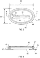
- FIGS 3 and 4 are enlarged views of an alternative embodiment of an assembly according to the invention.
- Window 45 is shown assembled with gasket 47, a groove 49 in gasket 47 sealingly engaging the peripheral edge of window 45.
- Figure 4 is a cross-section view showing the assembly of window 45 and gasket 47 adjacent an inner surface 51 of an inner wall 53 of a waveguide, window 45 being located over a slot antenna 55.
- a clearance distance 57 from between inner surface 51 and window 47 is preferably less than approximately 0.375 in. [0.9525cm], and the thickness of window 47 is preferably less than approximately 0.125 in [0.3175cm].
- slot antenna 55 has a length dimension 59 of approximately 2.4 in [6.096cm]. and a width dimension 61 of 0.25 in [0.635cm].
- window 47 is sized to have a preferred length dimension of length dimension 63 of approximately 3.5 in. [8.89cm] and a width dimension 65 of 2.5 in. [6.35cm].
- the gasket that carries the windows may be formed as two pieces. In this configuration, at least one gasket piece is located between the rim of the sealing flange and the oven cavity side of the window, and at least one gasket piece is located between the inner surface of the waveguide inner wall and the waveguide side of the window.
Landscapes
- Engineering & Computer Science (AREA)
- Chemical & Material Sciences (AREA)
- Combustion & Propulsion (AREA)
- Mechanical Engineering (AREA)
- General Engineering & Computer Science (AREA)
- Physics & Mathematics (AREA)
- Electromagnetism (AREA)
- Life Sciences & Earth Sciences (AREA)
- Food Science & Technology (AREA)
- Constitution Of High-Frequency Heating (AREA)
- Electric Ovens (AREA)
Description
- The present invention relates generally to covers for antennas and specifically to cover assemblies for slot antennas located within the cook chamber of an oven.
- A rapid-cook oven combines microwave (or radio frequency) cooking and convection cooking for cooking food products in a cook chamber. In one type of rapid-cook oven, the microwave portion comprises waveguides positioned along the left and right hand chamber walls. The covers (forming portions of cook chamber walls) of the waveguides are fitted with slotted antennas, which are slots formed in the waveguide cover. The slots are rectangular holes in the metal waveguides, and these may be, for example, approximately 2.39 inches long (6.07 cm) by approximately 0.25 inches wide (0.64 cm) (with rounded, or radiused, ends) for use with the energy frequency produced by 2.45GHz magnetron tubes. These antennas are associated with standard 2.45GHz magnetron tubes producing a maximum power level for the oven of around 1950 watts delivered to the food (or about 975 watts per tube). The number of slot antennas per side may vary, but current versions use 3 slot antennas per side.
- The microwave slot antenna is within the cook chamber, and the antenna for a commercial oven may experience a maximum operating temperature of around 550°F (287.78° C). In addition, the antennas are open to the cooking chamber environment, so they must be sealed to prevent food particles, water, oil, cleaning agents, or other substances from being deposited in the waveguide. Contamination of the waveguide interior by such substances can reduce the life of the magnetron tube, reduce the useful power produced by the tube, and/or increase heat loss from the oven.
- Although great strides have been made in the area of covers for microwave oven antennas, many short comings remain.
-
US4316069 A discloses a microwave oven with a microwave waveguide communicating with the oven cavity through a wall of the oven cavity. -
DE 3119596 A1 andEP0029532 disclose a combined microwave and resistance heating oven in which a plate is mounted with a frame and seal to separate the cooking chamber from a microwave generator housed below the cooking chamber. -
JP-62 218736 -
US3263052 discloses an oven comprising a waveguide comprising slot antennas located within the cook chamber of the oven. - There is a need in the art for an improved cover for an antenna located within the cook chamber of an oven.
- This object is achieved by providing an oven as claimed.
- An antenna cover assembly for a high-temperature operating environment has a cover plate, gasket portions, and a retainer plate. The cover plate has an inner side and an outer side, the cover plate being translucent to at least one selected frequency of electromagnetic energy. The gasket portions are each located adjacent one of the inner and outer sides, each gasket portion being configured for sealingly engaging the adjacent side. The retainer plate is configured for attachment to a structure located in a high-temperature operating environment. The retainer plate has a sealing flange adapted for clamping the cover plate generally adjacent an antenna portion of a waveguide.
- The novel features believed to be characteristic of the invention are set forth in the appended claims. However, the invention itself, as well as a preferred mode of use, and further objectives and advantages thereof, will best be understood by reference to the following detailed description when read in conjunction with the accompanying drawings, wherein:
-
Figure 1 is a front view of a portion of a waveguide and cover assembly according to the invention, the figure showing a preferred embodiment of a cover according to the present invention; -
Figure 2 is a cross-section view of the assembly ofFigure 1 taken along the line 2-2; -
Figure 3 is a front view of an alternative embodiment of a cover plate and gasket assembly according to the invention; and -
Figure 4 is cross-section view of the assembly ofFigure 3 taken along the line 4-4. - The present invention is directed to an improved antenna cover for ovens that operate using electromagnetic energy, such as microwave or radio frequency (RF) energy, emitted through slot antennas located in a high-temperature cook chamber, such as in a combination microwave and convection oven.
- To reliably seal the slot antennas and associated waveguides while providing a low loss (E/H energy) interface to the cooking cavity, the present invention provides a very durable and low-cost cover for slot antennas. The cover plate material must be compatible with a high-temperature operating environment (such as the interior of a convention oven), must be of low-loss characteristics relative to microwave (or RF) transmission, easily cleaned, durable, and inexpensive. Suitable cover plate, or window, material can be either flexible or rigid. For good microwave compatibility, materials with a dielectric constant less than approximately 6.0 and a loss tangent less than approximately 0.2 are preferred. In addition, the cover assembly must prevent moisture and/or grease from passing from the oven cavity to the interior of the waveguide.
- Ceramic or rigid style cover plate materials include high-purity quartz and alumina. These materials have excellent high-temperature thermal characteristics, very good microwave transmission performance and offer good protection against user abuse. However, using these materials requires designs to be created with several considerations in mind.
- For example, ceramic plates are susceptible to cracking or other damage if the window mounting structure that attaches the window to the oven cavity wall distorts, bends, or twists due to oven operation at an elevated temperature. When an oven wall made of sheet metal becomes hot, the wall distorts and can cause tensile stresses (primarily bending) in the ceramic window if the window is clamped directly to the cavity. In addition, these potential stresses increase as the size of the ceramic window increases.
- Because ceramic cover plates have a very low coefficient of thermal expansion when compared to the oven sheet metal, another consideration is that bonding the ceramic directly to the sheet metal to create an edge seal is not effective for achieving a reliable, long-life seal. The seal is needed to prevent water and grease from seeping between the metal/ceramic interface, and a flexible interface gasket is required for good, long-life sealing. A further consideration is that high-purity ceramics are relatively expensive materials. To reduce material costs, the ceramics should cover only the slot antenna broadcast area and be as thin as possible.
-
Figures 1 and 2 are front and cross-section views of a portion of a waveguide andcover assembly 11. Waveguide 13 is installed within an oven cook cavity and comprises anouter wall 15 and aninner wall 17.Walls waveguide cavity 19.Waveguide cavity 19 is in communication with a magnetron (not shown) or other electromagnetic energy emitter for guiding the emitted energy into the oven cavity.Slot antennas 21 are formed ininner wall 15 for permitting energy to be emitted throughinner wall 17 into the cook cavity of the oven. - To prevent grease, food particles, or other materials within the oven cavity from entering
waveguide cavity 19, ceramic cover plates, orwindows 23, are located generally adjacent eachslot antenna 21. In the embodiment shown, eachwindow 23 is carried by a unitary o-ring gasket 25, which is retained in place by aretainer plate 27. A peripheral edge ofwindow 23 is sealingly carried in agroove 26, which is formed in an inner portion ofgasket 25.Retainer plate 27 is a rigid, generally planarmember having flanges retainer plate 27 to the oven wall.Retainer plate 27 is preferably made from sheet metal, but may alternatively be made from other materials that are suitable for a high-temperature environment. For eachslot antenna 21, asealing flange 33 is formed inretainer plate 27, eachsealing flange 33 extending toward the oven cavity and having dimensions larger that those ofslot antennas 21. Eachsealing flange 33 has aninner rim 35 sized and configured for sealinglyengaging gasket 25 about the periphery ofwindow 23. - To seal
windows 23 towaveguide 13,gasket 25 is clamped betweenrim 35 andinner surface 37 ofinner wall 17. Aninner sealing interface 39 is formed betweengasket 25 andrim 35, and anouter sealing interface 41 is formed betweengasket 25 andsurface 37 ofinner wall 17. This allowsgasket 25 to providesealing interfaces waveguide 13 from the oven cavity and provide a compliant foundation for accommodating local twisting, bending, and displacement of the associated sheet metal components. This foundation greatly reduces bending stresses on eachwindow 23. In addition, the use of a separate smaller window for eachslot antenna 21, as compared to a large sheet of material covering allslot antennas 21, reduces material costs and further reduces stress inwindows 21 by permittingwindows 21 to translate and rotate relative to each other. Sealing interfaces 39, 41 create a redundant sealing geometry, such that any grease, water, or cooking residue must pass by both sealinginterfaces slot antenna 21 andwaveguide 13. -
Sealing flanges 33, which are spaced frominner wall 17, may act as reflectors to an energy beam 43 (with side lobes) emitted fromslot antenna 21. Therefore,windows 23 must have enough viewing area relative toenergy beam 43 to permitbeam 43 to radiate from eachantenna 21 with minimal reflection of power back toantennas 21.Figures 3 and 4 are enlarged views of an alternative embodiment of an assembly according to the invention.Window 45 is shown assembled withgasket 47, agroove 49 ingasket 47 sealingly engaging the peripheral edge ofwindow 45.Figure 4 is a cross-section view showing the assembly ofwindow 45 andgasket 47 adjacent aninner surface 51 of aninner wall 53 of a waveguide,window 45 being located over aslot antenna 55. - In the embodiment shown, a
clearance distance 57 from betweeninner surface 51 andwindow 47 is preferably less than approximately 0.375 in. [0.9525cm], and the thickness ofwindow 47 is preferably less than approximately 0.125 in [0.3175cm]. As shown inFigure 3 ,slot antenna 55 has alength dimension 59 of approximately 2.4 in [6.096cm]. and awidth dimension 61 of 0.25 in [0.635cm]. To limit or eliminate reflection of energy emitted throughantenna 55,window 47 is sized to have a preferred length dimension oflength dimension 63 of approximately 3.5 in. [8.89cm] and awidth dimension 65 of 2.5 in. [6.35cm]. - While shown in the embodiments as being a unitary gasket, the gasket that carries the windows may be formed as two pieces. In this configuration, at least one gasket piece is located between the rim of the sealing flange and the oven cavity side of the window, and at least one gasket piece is located between the inner surface of the waveguide inner wall and the waveguide side of the window.
Claims (5)
- An oven comprising:-a waveguide (13) comprising slot antennas (21,55) located within the cook chamber of the oven;characterized in further comprising:located generally adjacent each slot antenna (21,55), cover plates (23,45) having an inner side and an outer side and being translucent to at least one selected frequency of electromagnetic energy;at least two elastomeric gasket portions, one of said elastomeric gasket portions being located adjacent the inner side of the cover plate (23,45), and one of said elastomeric gasket portions being located adjacent the outer side of the cover plate (23,45), each gasket portion being configured for sealingly engaging the adjacent side;a retainer plate (27) having flanges (29, 31) configured for attaching retainer plate (27) to the oven wall, and having a sealing flange (33) for each slot antenna (21,55), adapted for clamping the cover plates (23,45) generally adjacent the slot antennas (21,55).
- An oven as claimed in Claim 1, wherein the at least two gasket portions are carried by a unitary gasket (25,47).
- An oven as claimed in Claim 2, wherein the gasket (25,47) has an inner groove (26,49) configured for engaging a periphery of the cover plate (23,45).
- An oven as claimed in any one of Claims 1 to 3, wherein the sealing flange (33) has a rim (35) offset from a plane of the antenna portion.
- An oven as claimed in any one of Claims 1 to 4, wherein the cover plate (23,45) is formed from a ceramic material.
Applications Claiming Priority (2)
| Application Number | Priority Date | Filing Date | Title |
|---|---|---|---|
| US11/928,007 US8658953B2 (en) | 2003-07-07 | 2007-10-30 | Antenna cover for microwave ovens |
| PCT/US2008/081689 WO2009058934A1 (en) | 2007-10-30 | 2008-10-30 | Antenna cover for microwave ovens |
Publications (2)
| Publication Number | Publication Date |
|---|---|
| EP2208254A1 EP2208254A1 (en) | 2010-07-21 |
| EP2208254B1 true EP2208254B1 (en) | 2016-05-11 |
Family
ID=40297664
Family Applications (1)
| Application Number | Title | Priority Date | Filing Date |
|---|---|---|---|
| EP08844134.0A Not-in-force EP2208254B1 (en) | 2007-10-30 | 2008-10-30 | Antenna cover for microwave ovens |
Country Status (3)
| Country | Link |
|---|---|
| US (1) | US8658953B2 (en) |
| EP (1) | EP2208254B1 (en) |
| WO (1) | WO2009058934A1 (en) |
Families Citing this family (35)
| Publication number | Priority date | Publication date | Assignee | Title |
|---|---|---|---|---|
| US9351495B2 (en) * | 2002-07-05 | 2016-05-31 | Turbochef Technologies, Inc. | Air fryer |
| EP1534999B1 (en) * | 2002-07-05 | 2017-11-01 | TurboChef Technologies, Inc. | Speed cooking oven |
| US8006685B2 (en) * | 2002-07-05 | 2011-08-30 | Turbochef Technologies, Inc. | Re-circulating oven with gas clean-up |
| US7886658B2 (en) * | 2003-07-07 | 2011-02-15 | Turbochef Technologies, Inc. | Speed cooking oven with improved radiant mode |
| US7946224B2 (en) * | 2003-07-07 | 2011-05-24 | Turbochef Technologies, Inc. | Griddle |
| US8011293B2 (en) * | 2003-07-07 | 2011-09-06 | Turbochef Technologies, Inc. | Speed cooking oven with sloped oven floor and reversing gas flow |
| US8658953B2 (en) | 2003-07-07 | 2014-02-25 | Turbochef Technologies, Inc. | Antenna cover for microwave ovens |
| US20080105249A1 (en) * | 2003-07-07 | 2008-05-08 | Turbochef Technologies, Inc. | Speed cooking oven with radiant mode |
| US8035062B2 (en) | 2003-07-07 | 2011-10-11 | Turbochef Technologies, Inc. | Combination speed cooking oven |
| US20050056946A1 (en) * | 2003-09-16 | 2005-03-17 | Cookson Electronics, Inc. | Electrical circuit assembly with improved shock resistance |
| CA2543060C (en) * | 2003-10-21 | 2011-05-03 | Turbochef Technologies, Inc. | Speed cooking oven with slotted microwave antenna |
| CA2558409A1 (en) * | 2004-03-05 | 2005-09-22 | Turbochef Technologies, Inc. | Conveyor oven |
| US8839527B2 (en) * | 2006-02-21 | 2014-09-23 | Goji Limited | Drying apparatus and methods and accessories for use therewith |
| WO2008102334A1 (en) | 2007-02-21 | 2008-08-28 | Rf Dynamics Ltd. | Rf controlled freezing |
| US8653482B2 (en) * | 2006-02-21 | 2014-02-18 | Goji Limited | RF controlled freezing |
| CN101427605B (en) | 2006-02-21 | 2013-05-22 | 戈吉有限公司 | Electromagnetic heating |
| US10674570B2 (en) | 2006-02-21 | 2020-06-02 | Goji Limited | System and method for applying electromagnetic energy |
| WO2008007368A2 (en) * | 2006-07-10 | 2008-01-17 | Rf Dynamics Ltd. | Food preparation |
| WO2008112606A2 (en) * | 2007-03-10 | 2008-09-18 | Turbochef Technologies, Inc. | Compact conveyor oven |
| IL184672A (en) | 2007-07-17 | 2012-10-31 | Eran Ben-Shmuel | Apparatus and method for concentrating electromagnetic energy on a remotely-located object |
| US9131543B2 (en) * | 2007-08-30 | 2015-09-08 | Goji Limited | Dynamic impedance matching in RF resonator cavity |
| ES2448216T3 (en) | 2008-11-10 | 2014-03-13 | Goji Limited | Device and method of heating using radiofrequency (RF) energy |
| JP5657016B2 (en) | 2009-11-10 | 2015-01-21 | ゴジ リミテッド | Apparatus and method for controlling energy |
| WO2011138675A2 (en) | 2010-05-03 | 2011-11-10 | Goji Ltd. | Modal analysis |
| GB201312634D0 (en) | 2013-07-15 | 2013-08-28 | Puresmoke Ltd | Method for smoking food and apparatus therefor |
| US9874358B2 (en) | 2015-05-05 | 2018-01-23 | Appliance Innovation, Inc. | Oven based on a combination of heated air and infrared heating element |
| US11639797B2 (en) | 2015-05-05 | 2023-05-02 | Ovention, Inc. | Cooking oven having an active vent |
| US9677774B2 (en) | 2015-06-08 | 2017-06-13 | Alto-Shaam, Inc. | Multi-zone oven with variable cavity sizes |
| US9879865B2 (en) | 2015-06-08 | 2018-01-30 | Alto-Shaam, Inc. | Cooking oven |
| US10088172B2 (en) | 2016-07-29 | 2018-10-02 | Alto-Shaam, Inc. | Oven using structured air |
| US10337745B2 (en) | 2015-06-08 | 2019-07-02 | Alto-Shaam, Inc. | Convection oven |
| US10890336B2 (en) | 2015-06-08 | 2021-01-12 | Alto-Shaam, Inc. | Thermal management system for multizone oven |
| FR3037729B1 (en) * | 2015-06-16 | 2017-06-09 | Illinois Tool Works | RADOME FOR PROTECTING ANTENNA OF EMISSION AND / OR RECEPTION OF WAVE |
| US10674571B2 (en) * | 2015-09-09 | 2020-06-02 | Illinois Tool Works, Inc. | Apparatus for providing RF stirring with solid state components |
| US10764971B2 (en) | 2016-11-30 | 2020-09-01 | Illinois Tool Works, Inc. | Waveguide assembly for an RF oven |
Citations (2)
| Publication number | Priority date | Publication date | Assignee | Title |
|---|---|---|---|---|
| US3263052A (en) * | 1963-09-11 | 1966-07-26 | Cryodry Corp | Power distribution system for microwave process chambers |
| EP0029532A1 (en) * | 1979-11-20 | 1981-06-03 | Licentia Patent-Verwaltungs-GmbH | Combined stove for microwave and for conventional resistance heating |
Family Cites Families (107)
| Publication number | Priority date | Publication date | Assignee | Title |
|---|---|---|---|---|
| US2563253A (en) | 1948-01-23 | 1951-08-07 | Abraham S Levin | Warming table |
| US2704802A (en) | 1952-05-22 | 1955-03-22 | Raytheon Mfg Co | Microwave ovens |
| GB977777A (en) | 1962-02-02 | 1964-12-16 | Lyons & Co Ltd J | Improvements in or relating to radio frequency ovens |
| US3328800A (en) * | 1964-03-12 | 1967-06-27 | North American Aviation Inc | Slot antenna utilizing variable standing wave pattern for controlling slot excitation |
| US3321314A (en) * | 1965-09-20 | 1967-05-23 | Cryodry Corp | Process for cooking bacon with microwave energy |
| US3548152A (en) | 1969-03-10 | 1970-12-15 | Chambers Corp | Self-cleaning oven having cooling and ventilating system |
| US3581038A (en) | 1969-05-02 | 1971-05-25 | Varian Associates | Microwave applicator employing a broadside radiator in a conductive enclosure |
| BE789508A (en) | 1971-10-08 | 1973-01-15 | Werner & Pfleiderer | CONTINUOUS TUNNEL OVEN FOR COOKING OR DRYING |
| US3973551A (en) | 1972-11-03 | 1976-08-10 | The Tappan Company | Powered circulation oven |
| US3828760A (en) | 1973-05-23 | 1974-08-13 | Lca Corp | Oven |
| DE2557867C3 (en) | 1975-12-22 | 1979-11-08 | Bosch-Siemens Hausgeraete Gmbh, 7000 Stuttgart | Convection oven |
| US4403128A (en) | 1976-03-11 | 1983-09-06 | Sharp Kabushiki Kaisha | Microwave oven with a capability of functioning as an electric heating oven |
| US4409453A (en) | 1976-05-19 | 1983-10-11 | Smith Donald P | Combined microwave and impingement heating apparatus |
| US4154861A (en) | 1976-05-19 | 1979-05-15 | Smith Donald P | Heat treatment of food products |
| US4338911A (en) | 1976-05-19 | 1982-07-13 | Smith Donald P | Cooking apparatus |
| US4133997A (en) * | 1977-02-09 | 1979-01-09 | Litton Systems, Inc. | Dual feed, horizontally polarized microwave oven |
| US4160144A (en) | 1978-01-25 | 1979-07-03 | Canadian Patents And Development Limited | Single-sided microwave applicator for sealing cartons |
| US4160145A (en) | 1978-02-16 | 1979-07-03 | Armstrong Cork Company | Microwave applicator device |
| US4283614A (en) | 1978-02-20 | 1981-08-11 | Matsushita Electric Industrial Co., Ltd. | Cooking device with high-frequency heating means and resistance heating means |
| US4210793A (en) * | 1978-03-06 | 1980-07-01 | Agence Nationale De Valorisation De La Recherche (Anvar) | Microwave applicator for radiating microwaves to an elongated zone |
| US4327274A (en) | 1978-08-21 | 1982-04-27 | General Electric Company | Ventilation system for combination microwave oven and exhaust vent |
| CA1114262A (en) | 1979-01-16 | 1981-12-15 | Raytheon Company | Gas burner convection oven |
| DE2907281A1 (en) | 1979-02-24 | 1980-09-04 | Ruhrchemie Ag | APPARATUS AND METHOD FOR MEASURING THE TEMPERATURE IN REACTORS OPERATING AT 1400 DEGREES CELSIUS |
| US4337384A (en) | 1979-08-01 | 1982-06-29 | Matsushita Electric Industrial Co., Ltd. | Cooking appliance of the hot air circulating type |
| DE2946767A1 (en) * | 1979-11-20 | 1981-06-11 | Licentia Patent-Verwaltungs-Gmbh, 6000 Frankfurt | COMBINED OVEN FOR MICROWAVE AND CONVENTIONAL RESISTANCE HEATING |
| US4327279A (en) | 1979-11-27 | 1982-04-27 | Sunsetl, Ltd. | Counter-top reheating unit for packaged pre-cooked meals |
| US4316069A (en) | 1979-12-03 | 1982-02-16 | General Electric Company | Microwave oven excitation system |
| US4350504A (en) | 1980-01-28 | 1982-09-21 | Century 21 Pollution Control, Inc. | Air cleaning system |
| US4494525A (en) | 1980-04-02 | 1985-01-22 | Corning Glass Works | Stove with catalytic converter |
| JPS56149531A (en) | 1980-04-22 | 1981-11-19 | Sharp Corp | Hot-air circulation type cooker |
| US4354083A (en) | 1980-11-05 | 1982-10-12 | General Electric Company | Microwave oven with novel energy distribution arrangement |
| DE3119596A1 (en) * | 1981-05-16 | 1982-12-02 | Licentia Patent-Verwaltungs-Gmbh, 6000 Frankfurt | Combined cooker for microwave heating operation and conventional resistance heating operation |
| US4516012A (en) | 1981-06-22 | 1985-05-07 | G. S. Blodgett Co., Inc. | Dual flow heating apparatus |
| US4431889A (en) | 1981-11-09 | 1984-02-14 | Raytheon Company | Combination microwave and convection oven |
| US4462383A (en) | 1982-06-09 | 1984-07-31 | Lincoln Manufacturing Company, Inc. | Impingement food preparation apparatus |
| US4464554A (en) | 1982-08-25 | 1984-08-07 | General Electric Company | Dynamic bottom feed for microwave ovens |
| US4480164A (en) | 1982-12-03 | 1984-10-30 | General Electric Company | Food browning system incorporating a combined microwave and hot air oven |
| US4786774A (en) | 1984-04-27 | 1988-11-22 | Sharp Kabushiki Kaisha | Combination compact microwave oven and ventilator system |
| JPS6230635A (en) | 1985-07-30 | 1987-02-09 | Chugai Ro Kogyo Kaisha Ltd | Evacuation furnace for cathode ray tube |
| DE3528229A1 (en) | 1985-08-06 | 1987-02-12 | Bosch Siemens Hausgeraete | ARRANGEMENT FOR CONTROLLING ELECTRICAL CONSUMERS IN OVENS |
| US4965435A (en) | 1985-10-15 | 1990-10-23 | Donald P. Smith | Forced convection tunnel oven |
| JPS62218736A (en) | 1986-03-19 | 1987-09-26 | Matsushita Electric Ind Co Ltd | Microwave heating device |
| US4743728A (en) | 1986-05-31 | 1988-05-10 | Kabushiki Kaisha Toshiba | Dual path air circulation system for microwave ovens |
| US4737373A (en) | 1987-02-11 | 1988-04-12 | Forney Robert B | Cooking and browning system |
| US4949629A (en) | 1987-10-13 | 1990-08-21 | Heat And Control, Inc. | Cooking a food product in a process vapor at progressively varying rates |
| DE3734958A1 (en) | 1987-10-15 | 1989-04-27 | Bosch Siemens Hausgeraete | CERAMIC COVER DISK WITH AN OPTIMIZED GEOMETRY FOR MICROWAVE OVENS |
| DE8801849U1 (en) | 1988-02-12 | 1988-03-31 | Bosch-Siemens Hausgeräte GmbH, 8000 München | Microwave household appliance |
| US4924763A (en) | 1988-10-17 | 1990-05-15 | Pizza Hut | Compact pizza oven |
| US4958412A (en) | 1988-12-09 | 1990-09-25 | W. R. Grace & Co.-Conn. | Method and apparatus for coating a food product |
| IT1236295B (en) | 1989-11-29 | 1993-02-02 | Zanussi Grandi Impianti Spa | COMBINED MICROWAVE COOKING OVEN AND FORCED CONVENTION |
| US5166487A (en) | 1989-12-15 | 1992-11-24 | Tecogen, Inc. | Cooking oven with convection and microwave heating |
| US5401940A (en) | 1990-01-10 | 1995-03-28 | Patentsmith Ii, Inc. | Oscillating air dispensers for microwave oven |
| US5717192A (en) | 1990-01-10 | 1998-02-10 | Patentsmith Technology, Ltd. | Jet impingement batch oven |
| US5025775A (en) | 1990-06-04 | 1991-06-25 | Lincoln Foodservice Products, Inc. | Air delivery system and oven control circuitry cooling system for a low profile impingement oven |
| US5161889A (en) | 1991-06-03 | 1992-11-10 | Patentsmith Ii, Inc. | Heat transfer rate target module |
| US5369250A (en) | 1991-09-27 | 1994-11-29 | Apv Corporation Limited | Method and apparatus for uniform microwave heating of an article using resonant slots |
| US5204503A (en) | 1991-12-17 | 1993-04-20 | Raytheon Company | Microwave oven having convection and griddle features |
| US5155318A (en) | 1991-12-17 | 1992-10-13 | Raytheon Company | Microwave oven griddle seal |
| US5277105A (en) | 1992-05-29 | 1994-01-11 | Middleby Marshall Corporation | Low profile stackable conveyor oven |
| BR9507898A (en) | 1994-05-25 | 1997-09-16 | Ultravection International Inc | Apparatus and process for cooking at least one first food item and device for cooking food in an octagonal chamber |
| US5555795A (en) | 1996-02-12 | 1996-09-17 | Tsai; Shu-Yen | Baking pot |
| US5994672A (en) | 1996-05-17 | 1999-11-30 | Air Fry, Inc. | Oil-free fryer, food cooker |
| US5826496A (en) | 1996-07-23 | 1998-10-27 | Stein, Inc. | Cooking oven |
| KR19980017873A (en) | 1996-08-31 | 1998-06-05 | 배순훈 | Microwave Waveguide Structure |
| US5934178A (en) | 1997-01-04 | 1999-08-10 | Heat & Control, Inc. | Air impingement oven |
| US5927265A (en) | 1997-05-27 | 1999-07-27 | Turbochef Technologies, Inc. | Recycling cooking oven with catalytic converter |
| US6060701A (en) | 1997-05-27 | 2000-05-09 | Turbochef Technologies, Inc. | Compact quick-cooking convectional oven |
| US6058924A (en) | 1997-05-27 | 2000-05-09 | Turbochef Technologies, Inc. | Vented recycling oven with separate catalytic converter |
| DE59906100D1 (en) | 1998-02-19 | 2003-07-31 | Framatome Anp Gmbh | METHOD AND DEVICE FOR MICROWAVE SINTERING OF FUEL |
| US6131559A (en) | 1998-05-23 | 2000-10-17 | Patentsmith Technology, Ltd. | Convection oven with smoke management means |
| US6114664A (en) | 1998-07-08 | 2000-09-05 | Amana Company, L.P. | Oven with combined convection and low mass, high power density heating |
| US6376817B1 (en) | 1998-10-09 | 2002-04-23 | Turbochef Technologies, Inc. | Compact quick-cooking oven |
| US6012442A (en) | 1998-10-29 | 2000-01-11 | Faraj; Abdul-Razzak | Outdoor grill |
| US6870123B2 (en) | 1998-10-29 | 2005-03-22 | Canon Kabushiki Kaisha | Microwave applicator, plasma processing apparatus having same, and plasma processing method |
| US7087872B1 (en) | 1999-04-19 | 2006-08-08 | Enersyst Development Center, L.L.C. | Multi-shelved convection microwave oven |
| US6369360B1 (en) | 1999-05-21 | 2002-04-09 | Maytag Corporation | Combination high speed infrared and convection conveyor oven and method of using |
| US6817283B2 (en) | 1999-08-04 | 2004-11-16 | Lincoln Foodservice Products, Inc. | High speed cooking device and method |
| US6472640B2 (en) | 1999-09-13 | 2002-10-29 | Maytag Corporation | Preheat system for convection cooking appliance |
| US6291808B1 (en) | 1999-09-13 | 2001-09-18 | Maytag Corporation | Heating system for a microwave and convection cooking appliance |
| GB2341677B (en) | 1999-11-20 | 2000-12-27 | Merrychef Ltd | Ovens with catalytic converters |
| DE10107289A1 (en) | 2000-03-14 | 2001-09-27 | Werner & Pfleiderer Lebensmitt | Tunnel baking oven has continuous baking conveyor belts driven at same direction and drivable at same or different rates, which run from inlet station to outlet station of each baking chamber |
| US6713741B2 (en) | 2000-04-28 | 2004-03-30 | Maytag Corporation | Conveyorized oven with automated door |
| US6403937B1 (en) | 2000-07-08 | 2002-06-11 | The Garland Group | Combination convection/microwave oven controller |
| KR100402495B1 (en) | 2000-11-30 | 2003-10-22 | 주식회사 엘지이아이 | A heater system for micro wave oven |
| FR2818359B1 (en) | 2000-12-15 | 2004-05-14 | Thirode Grandes Cuisines Poligny | OVEN DEVICE AND OVEN CONTROL METHOD |
| US6655373B1 (en) | 2001-11-14 | 2003-12-02 | Middleby Marshall, Incorporated | High efficiency conveyor oven |
| US7308852B2 (en) | 2001-12-28 | 2007-12-18 | Sharp Kabushiki Kaisha | Heating cooking device |
| US6732637B2 (en) | 2002-06-06 | 2004-05-11 | Qnc, Inc. | Forced convection and radiant heat cooking |
| US8006685B2 (en) | 2002-07-05 | 2011-08-30 | Turbochef Technologies, Inc. | Re-circulating oven with gas clean-up |
| WO2005087009A1 (en) * | 2003-07-07 | 2005-09-22 | Global Appliance Technologies, Inc. | Conveyor oven |
| US9351495B2 (en) | 2002-07-05 | 2016-05-31 | Turbochef Technologies, Inc. | Air fryer |
| EP1534999B1 (en) | 2002-07-05 | 2017-11-01 | TurboChef Technologies, Inc. | Speed cooking oven |
| US6909078B2 (en) * | 2002-12-27 | 2005-06-21 | Lg Electronics Inc. | Cooking chamber assembly in microwave oven |
| WO2004064467A1 (en) * | 2003-01-16 | 2004-07-29 | Fujitsu Limited | Multilayer wiring board, method for producing the same, and method for producing fiber reinforced resin board |
| US6933477B2 (en) | 2003-04-10 | 2005-08-23 | Maytag Corporation | Menu driven control system for a cooking appliance |
| JP2004349042A (en) * | 2003-05-21 | 2004-12-09 | Matsushita Electric Ind Co Ltd | High frequency heating equipment |
| US7946224B2 (en) | 2003-07-07 | 2011-05-24 | Turbochef Technologies, Inc. | Griddle |
| US8011293B2 (en) | 2003-07-07 | 2011-09-06 | Turbochef Technologies, Inc. | Speed cooking oven with sloped oven floor and reversing gas flow |
| US8035062B2 (en) | 2003-07-07 | 2011-10-11 | Turbochef Technologies, Inc. | Combination speed cooking oven |
| US8658953B2 (en) | 2003-07-07 | 2014-02-25 | Turbochef Technologies, Inc. | Antenna cover for microwave ovens |
| US20080105249A1 (en) | 2003-07-07 | 2008-05-08 | Turbochef Technologies, Inc. | Speed cooking oven with radiant mode |
| US7886658B2 (en) | 2003-07-07 | 2011-02-15 | Turbochef Technologies, Inc. | Speed cooking oven with improved radiant mode |
| CA2543060C (en) | 2003-10-21 | 2011-05-03 | Turbochef Technologies, Inc. | Speed cooking oven with slotted microwave antenna |
| CA2558409A1 (en) | 2004-03-05 | 2005-09-22 | Turbochef Technologies, Inc. | Conveyor oven |
| WO2006060751A2 (en) * | 2004-12-03 | 2006-06-08 | Turbochef Technologies, Inc | High speed convection oven |
| US7468495B2 (en) | 2005-05-06 | 2008-12-23 | Viking Range Corporation | Multi-mode convection oven with flow control baffles |
| WO2008112606A2 (en) | 2007-03-10 | 2008-09-18 | Turbochef Technologies, Inc. | Compact conveyor oven |
-
2007
- 2007-10-30 US US11/928,007 patent/US8658953B2/en not_active Expired - Fee Related
-
2008
- 2008-10-30 EP EP08844134.0A patent/EP2208254B1/en not_active Not-in-force
- 2008-10-30 WO PCT/US2008/081689 patent/WO2009058934A1/en not_active Ceased
Patent Citations (2)
| Publication number | Priority date | Publication date | Assignee | Title |
|---|---|---|---|---|
| US3263052A (en) * | 1963-09-11 | 1966-07-26 | Cryodry Corp | Power distribution system for microwave process chambers |
| EP0029532A1 (en) * | 1979-11-20 | 1981-06-03 | Licentia Patent-Verwaltungs-GmbH | Combined stove for microwave and for conventional resistance heating |
Also Published As
| Publication number | Publication date |
|---|---|
| US20080106483A1 (en) | 2008-05-08 |
| EP2208254A1 (en) | 2010-07-21 |
| US8658953B2 (en) | 2014-02-25 |
| WO2009058934A1 (en) | 2009-05-07 |
Similar Documents
| Publication | Publication Date | Title |
|---|---|---|
| US8658953B2 (en) | Antenna cover for microwave ovens | |
| US4390767A (en) | Windowed and choked combination oven door | |
| EP2031939B1 (en) | A wave choke device for a microwave oven door | |
| US4675507A (en) | Heat cooking apparatus having a flat flexible heater | |
| CA1163682A (en) | Microwave oven feed system | |
| US20210348768A1 (en) | Sealing system for an oven cavity | |
| EP2257121B1 (en) | A microwave oven with at least one wave choke system | |
| GB2126060A (en) | High-frequency heating apparatus | |
| RU2596806C2 (en) | Electronic lamp | |
| GB2198621A (en) | Baking oven door with viewing window | |
| JP5355205B2 (en) | Cooker | |
| JPS5948517B2 (en) | High frequency heating device | |
| CN1921712B (en) | Heating device using electromagnetic waves | |
| US4412117A (en) | Microwave oven feed system | |
| EP1758432B1 (en) | Heating apparatus using electromagnetic waves | |
| US4449025A (en) | Door seal construction for high frequency heating appliance | |
| EP0131324A2 (en) | A method of manufacturing doors for domestic ovens combining microwave and electrical resistance heating | |
| EP0121893A2 (en) | A door for a combination gas or electric and microwave oven | |
| US7327088B2 (en) | Magnetron | |
| KR100518417B1 (en) | Intercept structure of microwave in door for microwave oven | |
| CN110934505A (en) | heating cooker | |
| CN216864314U (en) | CVD window for improving microwave transmittance | |
| KR101203871B1 (en) | Apparatus for cooking | |
| EP0278564B1 (en) | An arrangement in a microwave oven | |
| JPH09126476A (en) | Microwave heater structure and method of manufacturing the same |
Legal Events
| Date | Code | Title | Description |
|---|---|---|---|
| PUAI | Public reference made under article 153(3) epc to a published international application that has entered the european phase |
Free format text: ORIGINAL CODE: 0009012 |
|
| 17P | Request for examination filed |
Effective date: 20100524 |
|
| AK | Designated contracting states |
Kind code of ref document: A1 Designated state(s): AT BE BG CH CY CZ DE DK EE ES FI FR GB GR HR HU IE IS IT LI LT LU LV MC MT NL NO PL PT RO SE SI SK TR |
|
| AX | Request for extension of the european patent |
Extension state: AL BA MK RS |
|
| RAP1 | Party data changed (applicant data changed or rights of an application transferred) |
Owner name: TURBOCHEF TECHNOLOGIES, INC. |
|
| DAX | Request for extension of the european patent (deleted) | ||
| 17Q | First examination report despatched |
Effective date: 20141006 |
|
| GRAP | Despatch of communication of intention to grant a patent |
Free format text: ORIGINAL CODE: EPIDOSNIGR1 |
|
| RIC1 | Information provided on ipc code assigned before grant |
Ipc: H01Q 1/42 20060101AFI20160128BHEP Ipc: F24C 15/32 20060101ALI20160128BHEP Ipc: H05B 6/64 20060101ALI20160128BHEP Ipc: A21B 1/24 20060101ALI20160128BHEP Ipc: H05B 6/72 20060101ALI20160128BHEP |
|
| INTG | Intention to grant announced |
Effective date: 20160212 |
|
| GRAS | Grant fee paid |
Free format text: ORIGINAL CODE: EPIDOSNIGR3 |
|
| GRAA | (expected) grant |
Free format text: ORIGINAL CODE: 0009210 |
|
| AK | Designated contracting states |
Kind code of ref document: B1 Designated state(s): AT BE BG CH CY CZ DE DK EE ES FI FR GB GR HR HU IE IS IT LI LT LU LV MC MT NL NO PL PT RO SE SI SK TR |
|
| REG | Reference to a national code |
Ref country code: GB Ref legal event code: FG4D |
|
| REG | Reference to a national code |
Ref country code: CH Ref legal event code: EP |
|
| REG | Reference to a national code |
Ref country code: AT Ref legal event code: REF Ref document number: 799306 Country of ref document: AT Kind code of ref document: T Effective date: 20160515 |
|
| REG | Reference to a national code |
Ref country code: IE Ref legal event code: FG4D |
|
| REG | Reference to a national code |
Ref country code: DE Ref legal event code: R096 Ref document number: 602008044232 Country of ref document: DE |
|
| REG | Reference to a national code |
Ref country code: NL Ref legal event code: FP |
|
| REG | Reference to a national code |
Ref country code: LT Ref legal event code: MG4D |
|
| REG | Reference to a national code |
Ref country code: FR Ref legal event code: PLFP Year of fee payment: 9 |
|
| PG25 | Lapsed in a contracting state [announced via postgrant information from national office to epo] |
Ref country code: NO Free format text: LAPSE BECAUSE OF FAILURE TO SUBMIT A TRANSLATION OF THE DESCRIPTION OR TO PAY THE FEE WITHIN THE PRESCRIBED TIME-LIMIT Effective date: 20160811 Ref country code: FI Free format text: LAPSE BECAUSE OF FAILURE TO SUBMIT A TRANSLATION OF THE DESCRIPTION OR TO PAY THE FEE WITHIN THE PRESCRIBED TIME-LIMIT Effective date: 20160511 Ref country code: LT Free format text: LAPSE BECAUSE OF FAILURE TO SUBMIT A TRANSLATION OF THE DESCRIPTION OR TO PAY THE FEE WITHIN THE PRESCRIBED TIME-LIMIT Effective date: 20160511 |
|
| PG25 | Lapsed in a contracting state [announced via postgrant information from national office to epo] |
Ref country code: LV Free format text: LAPSE BECAUSE OF FAILURE TO SUBMIT A TRANSLATION OF THE DESCRIPTION OR TO PAY THE FEE WITHIN THE PRESCRIBED TIME-LIMIT Effective date: 20160511 Ref country code: HR Free format text: LAPSE BECAUSE OF FAILURE TO SUBMIT A TRANSLATION OF THE DESCRIPTION OR TO PAY THE FEE WITHIN THE PRESCRIBED TIME-LIMIT Effective date: 20160511 Ref country code: SE Free format text: LAPSE BECAUSE OF FAILURE TO SUBMIT A TRANSLATION OF THE DESCRIPTION OR TO PAY THE FEE WITHIN THE PRESCRIBED TIME-LIMIT Effective date: 20160511 Ref country code: ES Free format text: LAPSE BECAUSE OF FAILURE TO SUBMIT A TRANSLATION OF THE DESCRIPTION OR TO PAY THE FEE WITHIN THE PRESCRIBED TIME-LIMIT Effective date: 20160511 Ref country code: GR Free format text: LAPSE BECAUSE OF FAILURE TO SUBMIT A TRANSLATION OF THE DESCRIPTION OR TO PAY THE FEE WITHIN THE PRESCRIBED TIME-LIMIT Effective date: 20160812 Ref country code: PT Free format text: LAPSE BECAUSE OF FAILURE TO SUBMIT A TRANSLATION OF THE DESCRIPTION OR TO PAY THE FEE WITHIN THE PRESCRIBED TIME-LIMIT Effective date: 20160912 |
|
| PG25 | Lapsed in a contracting state [announced via postgrant information from national office to epo] |
Ref country code: IT Free format text: LAPSE BECAUSE OF FAILURE TO SUBMIT A TRANSLATION OF THE DESCRIPTION OR TO PAY THE FEE WITHIN THE PRESCRIBED TIME-LIMIT Effective date: 20160511 |
|
| PG25 | Lapsed in a contracting state [announced via postgrant information from national office to epo] |
Ref country code: SK Free format text: LAPSE BECAUSE OF FAILURE TO SUBMIT A TRANSLATION OF THE DESCRIPTION OR TO PAY THE FEE WITHIN THE PRESCRIBED TIME-LIMIT Effective date: 20160511 Ref country code: EE Free format text: LAPSE BECAUSE OF FAILURE TO SUBMIT A TRANSLATION OF THE DESCRIPTION OR TO PAY THE FEE WITHIN THE PRESCRIBED TIME-LIMIT Effective date: 20160511 Ref country code: DK Free format text: LAPSE BECAUSE OF FAILURE TO SUBMIT A TRANSLATION OF THE DESCRIPTION OR TO PAY THE FEE WITHIN THE PRESCRIBED TIME-LIMIT Effective date: 20160511 Ref country code: CZ Free format text: LAPSE BECAUSE OF FAILURE TO SUBMIT A TRANSLATION OF THE DESCRIPTION OR TO PAY THE FEE WITHIN THE PRESCRIBED TIME-LIMIT Effective date: 20160511 Ref country code: RO Free format text: LAPSE BECAUSE OF FAILURE TO SUBMIT A TRANSLATION OF THE DESCRIPTION OR TO PAY THE FEE WITHIN THE PRESCRIBED TIME-LIMIT Effective date: 20160511 |
|
| REG | Reference to a national code |
Ref country code: DE Ref legal event code: R097 Ref document number: 602008044232 Country of ref document: DE |
|
| PG25 | Lapsed in a contracting state [announced via postgrant information from national office to epo] |
Ref country code: BE Free format text: LAPSE BECAUSE OF FAILURE TO SUBMIT A TRANSLATION OF THE DESCRIPTION OR TO PAY THE FEE WITHIN THE PRESCRIBED TIME-LIMIT Effective date: 20160511 Ref country code: PL Free format text: LAPSE BECAUSE OF FAILURE TO SUBMIT A TRANSLATION OF THE DESCRIPTION OR TO PAY THE FEE WITHIN THE PRESCRIBED TIME-LIMIT Effective date: 20160511 |
|
| PLBE | No opposition filed within time limit |
Free format text: ORIGINAL CODE: 0009261 |
|
| STAA | Information on the status of an ep patent application or granted ep patent |
Free format text: STATUS: NO OPPOSITION FILED WITHIN TIME LIMIT |
|
| 26N | No opposition filed |
Effective date: 20170214 |
|
| PG25 | Lapsed in a contracting state [announced via postgrant information from national office to epo] |
Ref country code: SI Free format text: LAPSE BECAUSE OF FAILURE TO SUBMIT A TRANSLATION OF THE DESCRIPTION OR TO PAY THE FEE WITHIN THE PRESCRIBED TIME-LIMIT Effective date: 20160511 |
|
| REG | Reference to a national code |
Ref country code: CH Ref legal event code: PL |
|
| PG25 | Lapsed in a contracting state [announced via postgrant information from national office to epo] |
Ref country code: MC Free format text: LAPSE BECAUSE OF FAILURE TO SUBMIT A TRANSLATION OF THE DESCRIPTION OR TO PAY THE FEE WITHIN THE PRESCRIBED TIME-LIMIT Effective date: 20160511 |
|
| REG | Reference to a national code |
Ref country code: IE Ref legal event code: MM4A |
|
| PG25 | Lapsed in a contracting state [announced via postgrant information from national office to epo] |
Ref country code: CH Free format text: LAPSE BECAUSE OF NON-PAYMENT OF DUE FEES Effective date: 20161031 Ref country code: LI Free format text: LAPSE BECAUSE OF NON-PAYMENT OF DUE FEES Effective date: 20161031 |
|
| PG25 | Lapsed in a contracting state [announced via postgrant information from national office to epo] |
Ref country code: LU Free format text: LAPSE BECAUSE OF NON-PAYMENT OF DUE FEES Effective date: 20161030 |
|
| REG | Reference to a national code |
Ref country code: FR Ref legal event code: PLFP Year of fee payment: 10 |
|
| PG25 | Lapsed in a contracting state [announced via postgrant information from national office to epo] |
Ref country code: IE Free format text: LAPSE BECAUSE OF NON-PAYMENT OF DUE FEES Effective date: 20161030 |
|
| PGFP | Annual fee paid to national office [announced via postgrant information from national office to epo] |
Ref country code: FR Payment date: 20171012 Year of fee payment: 10 Ref country code: DE Payment date: 20171025 Year of fee payment: 10 |
|
| REG | Reference to a national code |
Ref country code: AT Ref legal event code: UEP Ref document number: 799306 Country of ref document: AT Kind code of ref document: T Effective date: 20160511 |
|
| PGFP | Annual fee paid to national office [announced via postgrant information from national office to epo] |
Ref country code: NL Payment date: 20171016 Year of fee payment: 10 Ref country code: AT Payment date: 20171010 Year of fee payment: 10 Ref country code: GB Payment date: 20171025 Year of fee payment: 10 |
|
| PG25 | Lapsed in a contracting state [announced via postgrant information from national office to epo] |
Ref country code: CY Free format text: LAPSE BECAUSE OF FAILURE TO SUBMIT A TRANSLATION OF THE DESCRIPTION OR TO PAY THE FEE WITHIN THE PRESCRIBED TIME-LIMIT Effective date: 20160511 Ref country code: HU Free format text: LAPSE BECAUSE OF FAILURE TO SUBMIT A TRANSLATION OF THE DESCRIPTION OR TO PAY THE FEE WITHIN THE PRESCRIBED TIME-LIMIT; INVALID AB INITIO Effective date: 20081030 |
|
| PG25 | Lapsed in a contracting state [announced via postgrant information from national office to epo] |
Ref country code: MT Free format text: LAPSE BECAUSE OF NON-PAYMENT OF DUE FEES Effective date: 20161031 Ref country code: IS Free format text: LAPSE BECAUSE OF FAILURE TO SUBMIT A TRANSLATION OF THE DESCRIPTION OR TO PAY THE FEE WITHIN THE PRESCRIBED TIME-LIMIT Effective date: 20160511 Ref country code: TR Free format text: LAPSE BECAUSE OF FAILURE TO SUBMIT A TRANSLATION OF THE DESCRIPTION OR TO PAY THE FEE WITHIN THE PRESCRIBED TIME-LIMIT Effective date: 20160511 |
|
| PG25 | Lapsed in a contracting state [announced via postgrant information from national office to epo] |
Ref country code: BG Free format text: LAPSE BECAUSE OF FAILURE TO SUBMIT A TRANSLATION OF THE DESCRIPTION OR TO PAY THE FEE WITHIN THE PRESCRIBED TIME-LIMIT Effective date: 20160511 |
|
| REG | Reference to a national code |
Ref country code: DE Ref legal event code: R119 Ref document number: 602008044232 Country of ref document: DE |
|
| REG | Reference to a national code |
Ref country code: NL Ref legal event code: MM Effective date: 20181101 |
|
| REG | Reference to a national code |
Ref country code: AT Ref legal event code: MM01 Ref document number: 799306 Country of ref document: AT Kind code of ref document: T Effective date: 20181030 |
|
| GBPC | Gb: european patent ceased through non-payment of renewal fee |
Effective date: 20181030 |
|
| PG25 | Lapsed in a contracting state [announced via postgrant information from national office to epo] |
Ref country code: NL Free format text: LAPSE BECAUSE OF NON-PAYMENT OF DUE FEES Effective date: 20181101 Ref country code: DE Free format text: LAPSE BECAUSE OF NON-PAYMENT OF DUE FEES Effective date: 20190501 |
|
| PG25 | Lapsed in a contracting state [announced via postgrant information from national office to epo] |
Ref country code: FR Free format text: LAPSE BECAUSE OF NON-PAYMENT OF DUE FEES Effective date: 20181031 |
|
| PG25 | Lapsed in a contracting state [announced via postgrant information from national office to epo] |
Ref country code: GB Free format text: LAPSE BECAUSE OF NON-PAYMENT OF DUE FEES Effective date: 20181030 Ref country code: AT Free format text: LAPSE BECAUSE OF NON-PAYMENT OF DUE FEES Effective date: 20181030 |