EP2207596B1 - System for tissue change monitoring during hifu treatment - Google Patents
System for tissue change monitoring during hifu treatment Download PDFInfo
- Publication number
- EP2207596B1 EP2207596B1 EP08830580.0A EP08830580A EP2207596B1 EP 2207596 B1 EP2207596 B1 EP 2207596B1 EP 08830580 A EP08830580 A EP 08830580A EP 2207596 B1 EP2207596 B1 EP 2207596B1
- Authority
- EP
- European Patent Office
- Prior art keywords
- tissue
- transducer
- hifu
- region
- image
- Prior art date
- Legal status (The legal status is an assumption and is not a legal conclusion. Google has not performed a legal analysis and makes no representation as to the accuracy of the status listed.)
- Not-in-force
Links
Images





Classifications
-
- A—HUMAN NECESSITIES
- A61—MEDICAL OR VETERINARY SCIENCE; HYGIENE
- A61N—ELECTROTHERAPY; MAGNETOTHERAPY; RADIATION THERAPY; ULTRASOUND THERAPY
- A61N7/00—Ultrasound therapy
- A61N7/02—Localised ultrasound hyperthermia
-
- A—HUMAN NECESSITIES
- A61—MEDICAL OR VETERINARY SCIENCE; HYGIENE
- A61B—DIAGNOSIS; SURGERY; IDENTIFICATION
- A61B90/00—Instruments, implements or accessories specially adapted for surgery or diagnosis and not covered by any of the groups A61B1/00 - A61B50/00, e.g. for luxation treatment or for protecting wound edges
- A61B90/36—Image-producing devices or illumination devices not otherwise provided for
- A61B90/37—Surgical systems with images on a monitor during operation
- A61B2090/378—Surgical systems with images on a monitor during operation using ultrasound
Definitions
- the present invention relates to an apparatus for the treatment of tissue, and in particular, for the non-invasive treatment of diseased tissue.
- HIFU high intensity focused ultrasound
- the techniques, methods, and apparatus discussed herein have applicability to the treatment of tissue in general, this discussion will focus primarily on the treatment of prostate tissue including Benign Prostatic Hyperplasia (BPH) and prostatic cancer.
- BPH Benign Prostatic Hyperplasia
- the disclosed apparatus and methods will find applications in localization and treatment of a wide range of diseases which manifest themselves in a localized or "focal" manner, including cancers of the breast, brain, liver, and kidney.
- the disclosed apparatus uses an intracavity probe which will be particularly useful for focal diseases which are accessible to a transesophageal, laparoscopic or transvaginal probe.
- a transvaginal probe according to the present invention will provide a minimally invasive sterilization procedure on an outpatient basis, as well as therapy for fibroids, and endometrial ablation. Additionally, in the case of a transducer with multiple focal lengths, blood vessels may be selectively targeted to effect coagulation and cauterization of internal bleeding.
- HIFU Therapy is defined as the provision of high intensity focused ultrasound to a portion of tissue at or proximate to a focus of a transducer. It should be understood that the transducer may have multiple foci and that HIFU Therapy is not limited to a single focus transducer, a single transducer type, or a single ultrasound frequency.
- HIFU Treatment is defined as the collection of one or more HIFU Therapies. A HIFU Treatment may be all of the HIFU Therapies administered or to be administered, or it may be a subset of the HIFU Therapies administered or to be administered.
- HIFU System is defined as a system that is at least capable of providing a HIFU Therapy.
- the apparatus comprises a transducer which is positionable proximate to the tissue and a positioning member coupled to the transducer and configured to position the transducer.
- the transducer is configured to emit ultrasound energy and to receive ultrasound energy.
- the apparatus further comprises a controller operably coupled to the transducer and to the positioning member and being configured to position the transducer with the positioning member and to operate the transducer in an imaging mode wherein images of the tissue in the treatment region are obtained from ultrasound energy sensed by the transducer and in a therapy mode, wherein a plurality of treatment sites are treated with a HIFU Therapy with the transducer.
- the controller is further configured to monitor a plurality of regions of interest in the treatment region and to determine a tissue change value for each region of interest based on a frequency analysis of at least two images.
- Each region of interest corresponds to a multi-dimensional portion in each of the at least two images.
- treatment the apparatus comprises a transducer which is positionable proximate to the tissue, the transducer being configured to emit ultrasound energy and to receive ultrasound energy; a to the transducer configured to the positioning member being coupled to the transducer and configured to position the transducer; and a controller operably coupled to the transducer and to the positioning member.
- the controller includes means for determining a tissue change value for a region of interest in the treatment region.
- a method a a of providing treatment to a treatment region of tissue comprises the steps of acquiring a first image including a treatment site prior to a direct treatment with a HIFU Therapy, performing the direct treatment of the treatment site with the HIFU Therapy, acquiring a second image including the treatment site subsequent to the direct treatment, and determining a tissue change value in a region of interest of the tissue based on a first power spectrum of a portion of the first image corresponding to the region of interest and a second power spectrum of a portion of the second image corresponding to the region of interest.
- the first image is a multi-dimensional image.
- the second image is a multi-dimensional image.
- the region of interest includes the treatment site.
- the method comprises the steps of: monitoring a level of a tissue change in a region of interest of the treatment region due to an indirect heating of the tissue in the region of interest in response to a direct treatment of at least one treatment sites with the HIFU Therapy in the treatment region outside of the region of interest and determining whether to provide a direct treatment with the HIFU Therapy to a treatment site within the region of interest based on the level of the tissue change.
- the level of the tissue change is determined by a comparison of the power spectra of at least two images including the region of interest.
- the method comprises the steps of: performing acquiring a first image including a treatment site prior to a direct treatment with a HIFU Therapy, the first image being a multi-dimensional image; performing the direct treatment of the treatment site with the HIFU Therapy; acquiring a second image including the treatment site subsequent to the direct treatment, the second image being a multi-dimensional image; determining an indication of a tissue change in a region of interest of the tissue from a frequency domain analysis of the first image and the second image; and providing a color-coded visual indicator on an image of the treatment region.
- the color-coded visual indicator provides an indication of a degree of tissue change.
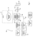
- Fig. 1 is schematic view of an exemplary HIFU System of the present invention, the HIFU System being capable of imaging the tissue of the patient and to provide HIFU Therapy to at least a portion of the tissue at or proximate to a focus of a transducer of the HIFU System;
- Fig. 2 is an exemplary embodiment of the HIFU System of Fig. 1 ;
- Fig. 3 is an exemplary method for treating tissue
- Fig. 4 is an exemplary method for treating tissue
- Fig. 5 represents exemplary sagittal image planes
- Fig. 6 represents exemplary echo signals received for a given sagittal image plane
- Fig. 7 represents a first exemplary method for the acquisition of 2D RF Data during a HIFU Treatment
- Fig. 8 represents a second exemplary method for the acquisition of 2D RF Data during a HIFU Treatment
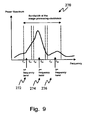
- Fig. 9 represents exemplary frequency bands of an exemplary power spectrum
- Fig. 10 is an exemplary method for determining a tissue change value
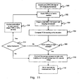
- Fig. 11 is an exemplary method for determining if an additional treatment is to be performed at a given treatment site
- Fig. 12 is an exemplary method to determine the parameters for a current treatment site based on the tissue change at a prior treatment site;
- Fig. 13 is an exemplary method to determine whether a given treatment site has been sufficiently treated by indirect treatment
- Fig. 14 is an exemplary screen shot of the display of the HIFU System of Fig. 1 illustrating inputs for modifying the gain parameters during a diagnostic mode of operation;
- Fig. 15 is an exemplary screen shot of the display of the HIFU System of Fig. 1 illustrating an image of the prostate including visual indicators of the tissue change and a summary of the TCM;
- Fig. 16 is a detail view of the summary of Fig. 15 ;
- Fig. 17 is an exemplary screen shot of the display of the HIFU System of Fig. 1 illustrating three-dimensional volumetric image including visual indicators of the tissue change.
- HIFU System 100 includes a probe 102 having a transducer member 104, a positioning member 106, a controller 108 operably coupled to probe 102 and the positioning member 106, a user input device 110 (such as keyboard, trackball, mouse, and/or touch screen), and a display 112.
- Probe 102 is operably connected to controller 108 through positioning member 106.
- Positioning member 106 is configured to linearly position transducer member 104 along directions 113, 114 and to angularly position transducer member 104 in directions 115, 116.
- Transducer member 104 is positioned generally proximate to a region of tissue 10. In the case of the prostate, transducer 104 is positioned generally proximate to the prostate by the transrectal insertion of probe 102. Transducer member 104 is moved by positioning member 106 and controlled by controller 108 to provide imaging of at least a portion of tissue 10 including at least one treatment region 12 and to provide HIFU Therapy to portions of the tissue within at least one treatment region 12. As such, HIFU System 100 may operate in an imaging mode wherein at least a portion of tissue 10 may be imaged and in a therapy mode wherein HIFU Therapy is provided to portions of tissue 10 within at least one treatment region. As stated herein, treatment region 12 is defined as one or more portions of tissue which are to be treated during a HIFU Treatment. Treatment region 12 is illustratively shown as a continuous region. However, a treatment region might involve two or more distinct regions.
- transducer member 104 is a single crystal two element transducer.
- An exemplary transducer is disclosed in U.S. Patent No. 5,117,832 .
- transducer 104 is capable of providing imaging of at least a portion of tissue 10 in an imaging mode and of providing HIFU Therapy to at least a portion of tissue 10 within treatment region 12 in a therapy mode.
- transducer which are phased arrays, such as the transducers disclosed in pending U.S. Patent Application Serial No. 11/070,371, filed March 2, 2005 , titled "Ultrasound Phased Arrays," Attorney Docket No. DUT-P001-0.
- Additional exemplary transducers and associated controls are disclosed in U.S. Patent No. 5,762,066 ; U.S. Abandoned Patent Application Serial No. 07/840,502 filed February 21, 1992 ; U.S. Patent No. 5,036,855 ; U.S. Patent No. 5,492,126 ; U.S. Patent No. 6,685,640 , U.S. Patent Application Serial No. 11/463,692 filed August 10, 2006 .
- a portion of probe 102 is covered by an acoustic membrane 103.
- Acoustic membrane 103 is an expandable membrane whose overall size is increased by placing a fluid on an interior of acoustic membrane 103.
- the fluid is water or a generally acoustic transparent material and is provided by a reservoir or a chiller. The fluid may be used to remove heat from proximate to transducer 104 as well as expanding acoustic membrane 103.
- acoustic membrane 103 is expanded such that it contacts or generally is adjacent to the surrounding tissue, such as a rectal wall.
- acoustic membrane 103 is a condom placed over a tip of probe 102, sealed with o-rings, and filled with water.
- Exemplary acoustic membranes and details of their operation in relation to respective other portions of exemplary HIFU Systems are provided in U.S. Patent No. 5,762,066 , U.S. Patent No. 5,993,389 , and U.S. Provisional Patent Application Serial No. 60/686,499, filed June 1, 2005 .
- controller 108 is configured to execute one or more of the methods discussed herein. In one embodiment, at least a portion of each method executed by controller 108 is provided as a portion of software 109.
- HIFU System 200 includes a console 202 which houses or supports a controller (not shown), such as a processor and associated software; a printer 204 which provides hard copy images of tissue 10 and/or reports; a user input device 206 such as a keyboard, trackball, and/or mouse; and a display 208 for displaying images of tissue 10 and software options to a user, such as a color display. Further, shown is a probe 210 which includes a transducer member (not shown), and a positioning member (not shown).
- an articulated probe arm 212 which is coupled to console 202. Articulated probe arm 212 orients and supports probe 210. A chiller 214 is also shown. Chiller 214, in one embodiment, provides a water bath with a heat exchanger for the transducer member of probe 210 to actively remove heat from the transducer member during a HIFU Treatment.
- HIFU System 100 provides HIFU Therapy to tissue 10.
- the characteristics of the tissue 10 changes due to the HIFU Therapy.
- Some HIFU-induced lesions in tissue 10 are visually detectable changes through standard 2-D ultrasound (echo) imaging techniques (i.e. the HIFU-induced tissue change is sufficiently large enough to create a noticeable difference between a BEFORE and an AFTER HIFU image that the operator can see).
- the application of HIFU may result in successful treatment of the tissue, even though these changes are not visually detectable through standard 2-D ultrasound (echo) imaging (i.e. cases wherein the tissue change due to HIFU is small or subtle enough so that it does not cause a noticeable change in standard ultrasound images).
- TCM tissue change monitoring methods
- TCM uses the same 2-D ultrasound echo data which is used for traditional ultrasound imaging.
- this ultrasound echo data is rectified, envelope-detected, log-scaled, and then mapped to a grayscale table for displaying on the screen.
- This processing removes the phase information from the ultrasound back scattered data and presents images based on intensity (square of pressure) values of the backscattered radio frequency signals.
- TCM uses the phase information and the amplitude information of the ultrasound data to determine the changes introduced to the tissue due to exposure to HIFU Therapy.
- the treatment region and surrounding tissue is imaged with HIFU System 100 using conventional ultrasound techniques.
- HIFU System 100 generates and stores a plurality of 2-D images of tissue 10 including treatment region 12.
- HIFU System 100 generates and stores a plurality of transverse or sector images about every 3 mm along the treatment region, such as image 121 in Fig. 15 , and generates and stores a plurality of sagittal (or linear) images about every 3° (as represented by image planes 250 in Fig. 5 ), such as image 123 in Fig. 15 .
- the sagittal images are comprised of a plurality of one-dimensional radio frequency echoes 252 (see Fig.
- each one-dimensional radio frequency echoes are included in the sagittal image with each one-dimensional radio frequency echo being spaced about 0.2 millimeters from adjacent one-dimensional radio frequency echoes.
- Each one-dimensional radio frequency echo is acquired at a corresponding transducer position along the x-axis 114. In other examples, different spacing of the transverse and sagittal images are used.
- treatment region is defined as one or more portions of tissue which are to be treated during a HIFU Treatment.
- treatment region is used to describe the overall area being treated during a HIFU Treatment.
- treatment region may also be used to describe one or more subregions of the overall area being treated, such as one or more treatment segment(s) and/or one or more treatment site(s).
- TCM provides a method for detecting changes in the tissue being treated with HIFU Therapy even if the HIFU Therapy does not result in large lesions that produce very large backscattered signals.
- TCM is the process of acquiring ultrasound backscattered RF echo data prior to, during, and/or after the delivery of HIFU Therapy, processing this data to determine a level of tissue change, assigning a visual indicia to the level of tissue change, and superimposing the visual indicia on an image of the treatment region.
- Exemplary images include standard 2D ultrasound images (such as images 121 and 123 in Fig. 15 ) and volumetric ultrasound images, such as image 125 in Fig. 17 .
- Image 125 includes a three-dimensional representation of the backscatter echo data, the visual indicator of the tissue change, and a representation of the position of the transducer 104.
- the HIFU System 100 Prior to delivering HIFU Therapy to create tissue changes, the HIFU System 100 acquires a reference image which includes the region that will be treated by the HIFU Therapy, as represented by block 302. This image is referred to as a BEFORE image.
- the BEFORE image may be acquired just prior to the application of HIFU Therapy or may be acquired many seconds prior to the application of HIFU Therapy.
- the BEFORE image is a sagittal image comprised of a plurality of one-dimensional echo signals.
- a region of interest is identified in the image, as represented by block 304.
- the ROI is a 2D sub-region which contains echoes of the tissue volume that will be treated by the HIFU transducer in a subsequent HIFU Treatment.
- the ROI includes the tissue located in the focal zone of the transducer (such as ROI 260 in Fig. 6 ).
- the ROI includes the tissue located in the region between the transducer and the focal zone of the transducer (such as ROI 262 in Fig. 6 ).
- the ROI includes the tissue located in the region beyond the focal zone of the transducer (such as ROI 264 in Fig. 6 ).
- the ROI includes the tissue located between the transducer and the focal zone of the transducer, located in the focal zone of the transducer, and located in the region beyond the focal zone of the transducer.
- the ROI is approximately from 10 millimeters to about 15 millimeters in depth and about 3 millimeters wide which corresponds to about 15 adjacent one-dimensional echo lines 252 in Fig. 6 .
- the RF data contained in the ROI is one of the two input data sets used to determine the tissue change value caused by an exposure to HIFU Therapy.
- the second input data set is the RF data from the ROI acquired subsequent to a HIFU exposure.
- An image is acquired after the HIFU exposure, as represented by block 306. This is referred to as an AFTER image.
- the same ROI is identified in the AFTER image, as represented by block 308.
- a parameter value representative of the tissue change is determined based on the BEFORE image and the AFTER image, as represented by block 310. In one embodiment, this parameter value is a level that is based on the tissue change value.
- a first BEFORE image is acquired at time To.
- a first HIFU Therapy is provided between time T 0 and time T 1 .
- a first AFTER image is acquired at time T 1 .
- a parameter value representative of the amount of tissue change during the first HIFU Therapy is determined.
- the first AFTER image is then used as a second BEFORE image.
- a second HIFU Therapy is provided between time T 1 and time T 2 .
- a second AFTER image is acquired at time T 2 .
- a parameter value representative of the amount of tissue change during the second HIFU Therapy is determined.
- the second AFTER image is then used as a third BEFORE image and the process continues to repeat.
- a first BEFORE image is acquired at time T 0 .
- a first HIFU Therapy is provided between time T 0 and time T 1 .
- a first AFTER image is acquired at time T 1 .
- a parameter value representative of the amount of tissue change during the first HIFU Therapy is determined.
- a second HIFU Therapy is provided between time T 1 and time T 2 .
- a second AFTER image is acquired at time T 2 .
- a parameter value representative of the amount of tissue change during the first HIFU Therapy and the second HIFU Therapy is determined.
- the first AFTER image is then used as a second BEFORE image.
- a third HIFU Therapy is provided between time T 2 and time T 3 .
- a third AFTER image is acquired at time T 3 .
- a parameter value representative of the amount of tissue change during the second HIFU Therapy and the third HIFU Therapy is determined.
- the second AFTER image is then used as a third BEFORE image and the process continues to repeat.
- the situation shown in Fig. 8 is beneficial in situations wherein successive treatment sites are in close proximity, such as next to each other.
- the HIFU Therapy for an n th treatment site may likely cause a tissue change in the adjacent n+1 treatment site due to heat conduction.
- the image recorded after the exposure of the nth treatment site is used as the BEFORE image of the n+1 treatment then a portion of the tissue change at the n+1 treatment site is not taken into account (the portion corresponding to the nth exposure).
- the BEFORE image prior to the nth exposure as the BEFORE image for the n+1 exposure the overall tissue change to the n+1 treatment site due to the nth exposure and the n+1 exposure may be determined.
- the parameter value representative of the level of tissue change is determined.
- a power spectrum is determined for each of the one dimensional echoes of the ROI for each of the BEFORE image and the AFTER image.
- two two-dimensional power spectra are known.
- One corresponding to the BEFORE image ROI and one corresponding to the AFTER image ROI are determined.
- An average power spectrum for each of the BEFORE image ROI and the AFTER image ROI are determined.
- two one-dimensional power spectra are known.
- the energy level of a plurality of frequency bands is determined.
- three frequency bands 272, 274, and 276 are determined for the averaged power spectrum 270 of the AFTER image.
- the same frequency bands are used in the averaged power spectrum of the BEFORE image.
- the energy levels for each of frequency bands 272, 274, and 276 are known.
- the determined energy level difference between the BEFORE image and the AFTER image is determined for each frequency band.
- the largest of the determined differences in one embodiment, is the parameter value representative of the level of tissue change between the BEFORE image and the AFTER image.
- the largest of the determined differences is mapped to a level of tissue change.
- a visual indicia indicative of the level of tissue change is displayed on the display 112 of HIFU System 100, as represented by block 312.
- the visual indicia is a color.
- the following table illustrates an exemplary mapping of the difference value to a visual indicator, a color, for a piece of chicken test tissue having an initial temperature of about 30 to about 35 degrees Celsius (C).
- the color is overlaid onto a displayed ultrasound image, such as image 123 in Fig. 15 , in a region corresponding to the treatment site in the ROI. This process is repeated for each successive BEFORE image and AFTER image.
- HIFU System 100 performs a diagnostic mode of operation 402 and a treatment mode of operation 404. HIFU System 100 further performs an imaging mode of operation in which images of treatment region 12 are acquired.
- a two dimensional reference image is acquired as represented by block 406.
- a pulse is sent into the tissue and the echoes from that pulse are digitized and converted into an image.
- the time for a given echo is directly proportional to the depth of the echo source.
- a gain parameter is applied to compensate for this physical phenomenon by generally increasing the gain for deeper tissue echoes.
- the gain parameter is generally known as either TGC which is an acronym for Time Gain Control or DGC which is an acronym for Depth Gain Control.
- the image is analyzed to determine if the signal to noise level is sufficient for TCM, as represented by block 408.
- the RF signals of the ultrasound image which correspond to a region of interest is examined.
- the mean of the absolute values of the RF signal is determined.
- the percentage of data points in the RF signal that are saturated is determined. A data point is saturated if its value exceeds or is equal to the maximum value that the analog to digital converter is able to digitize. If the mean value of the RF signal is below a threshold then the gain parameter is increased (as represented by block 409) and another ultrasound image is taken and the RF signal is tested once again. This approach helps prevent false positive readings due to poor signal to noise level from cysts (dark areas) in the tissue.
- An exemplary mean value threshold is about 10% of maximum digitization value. If the percent of saturated data points is above a threshold, then the gain parameter is decreased and another ultrasound image is taken and the RF signal is tested once again. This approach helps prevent false negative readings from excessively large signals caused by high gain in settings in the ultrasound image (saturation).
- An exemplary threshold percentage is about 0.1 percent. Assuming that both the mean value and the saturation percentage satisfy their respective thresholds, a HIFU Therapy including tissue change monitoring may be performed. If one or both of the mean value and the saturation percentage do not satisfy their respective thresholds, then a HIFU Therapy may still be performed. TCM may still be on in each HIFU treatment sites except where the mean value does not satisfy the threshold.
- both a signal to noise level and a RF saturation level are determined and presented with a scale meter 280 (see Fig. 14 ) on the display 112 of HIFU System 100.
- the operator may make fine adjustments for a gain parameter with input controls 282A-H in Fig. 14 and a main gain with input control 284 in Fig. 14 .
- the gain parameters corresponding to input controls 282A-H each correspond to a given depth range. As such, the gain for various depths may be adjusted independently.
- the main gain input 284 adjusts the gain for all depths at the same time.
- a BEFORE image is acquired for a treatment region, as represented by block 410.
- the BEFORE image is a two-dimensional image, such as a sagittal image, that includes the plane of the upcoming HIFU exposure (i.e. a plane containing the focal point of the transducer).
- the BEFORE image is stored in memory.
- HIFU Therapy is applied to the tissue as represented by block 412.
- an AFTER image is acquired for the treatment region, as represented by block 414.
- the AFTER image like the BEFORE image, in one embodiment is a two-dimensional image that includes the plane in which the HIFU Therapy was directed.
- the AFTER image is stored in memory.
- the BEFORE image is examined to determine whether the signal has a sufficient signal to noise ratio to be analyzed for tissue change monitoring, as represented by blocks 416 and 418.
- the mean of the absolute values of RF data in the treatment region in the BEFORE image is determined. If the mean value is below a threshold, then the BEFORE image is not considered appropriate for analyzing for tissue change monitoring and a tissue change indicator is set to "no data", as represented by block 420.
- the indicator is a visual indicator on the display of HIFU System 100. If the mean value satisfies the threshold, then the amount of tissue change is determined, as represented by block 422.
- An exemplary method for determining the amount of tissue change is provided in Fig. 10 discussed herein.
- a parameter value is determined which provides an indication of the level of tissue change.
- the parameter is an energy increase.
- the parameter is mapped to a visual indicator and displayed on display of HIFU System 100, as represented by block 424.
- the visual indicator is a color and the visual indicator is overlaid on a two-dimensional image of the treatment region and embedded into a three-dimensional volume image.
- discrete colors are provided which correspond to discrete levels of energy increase.
- a green color code corresponds to no (or very small) tissue change
- a yellow color code corresponds to a moderate tissue change
- an orange corresponds to a large tissue change.
- an exemplary BEFORE image and an exemplary AFTER image are both in a plane 250 and are acquired by translating transducer in the x-direction 114. At each discrete location in the x-direction 114 a one dimensional echo signal 252 is recorded. An exemplary spacing of the discrete locations is about 0.2 millimeters.
- a plurality of one-dimensional echo signals 252 are shown in Fig. 6 .
- about 200 to about 250 one-dimensional echo lines 252 are included in each of the BEFORE image an the AFTER image.
- about 225 one-dimensional echo lines 252 are included in each of the BEFORE image and the AFTER image.
- a width of a region of interest is comprised of a discrete number of one-dimensional echo lines 252.
- An exemplary width is about 15 one-dimensional echo lines 252 at a spacing of about 0.2 millimeters. This width is associated with a first treatment site. The fifteen adjacent one-dimensional echo lines 252 arc associated with a second treatment site, although not necessarily second in time.
- a first region of interest 260 corresponds to the focal zone. In one example, the first region corresponds to a depth of about 3.5 cm to about 4.5 cm.
- a second region of interest 262 corresponds to a pre-focal region. In one example, the second region of interest corresponds to a depth of about 2.8 cm to about 3.5 cm.
- the detection of pre-focal heating may be able to save therapy time by optimizing the radial overlap of consecutive therapy zones.
- a third region of interest 264 corresponding to the region beyond the focal zone (beyond the first region of interest) is also monitored. Additional regions of interest such as for other treatment sites may also be monitored.
- the parameter corresponding to the tissue change in a given region of interest is determined.
- the power spectrum for the region of interest for each of the BEFORE image and the AFTER image is determined, as represented by block 440.
- the time domain echoes signals for each one-dimensional echo line in the region of interest are converted to the frequency domain for the depth range corresponding to the region of interest for both the BEFORE image and the AFTER image.
- a discrete Fourier transform is used to convert the respective signals to the frequency domain.
- the converted signals are then averaged for each of the BEFORE image and the AFTER image to form a single power spectrum for each of the BEFORE image and the AFTER image. It should be noted if multiple regions of interest are being monitored then power spectra for those regions of interest in the BEFORE image and the AFTER image are also determined.
- An exemplary power spectrum 270 is illustrated in Fig. 9 for a region of interest corresponding to the focal zone of the transducer at a given treatment site.
- a plurality of frequency bands 272, 274, 276 are indicated on the power spectrum.
- the frequency bands correspond to a fundamental frequency band 274, a sub-harmonic frequency band 272, and a harmonic frequency band 276 by way of example.
- the fundamental frequency band correspond to the bandwidth of about 3 megahertz (MHZ) to about 5 MHz
- the sub-harmonic frequency band corresponds to a bandwidth of about 1 MHz to about 3 MHz
- the harmonic frequency band corresponds to the bandwidth of about 6 MHz to about 9 MHz.
- the change in energy in each of the frequency bands 272, 274, 276 between the BEFORE image and the AFTER image is determined, as represented by block 442.
- the average power spectrum for each frequency band in both of the BEFORE image and the AFTER image are determined.
- E SH is the average of power spectrum in dB scale in the sub-harmonic band
- P avg ( f ) is the average power spectrum
- f L1 is the lower frequency boundary of the sub-harmonic band 272
- f H1 is the upper frequency boundary of the sub-harmonic band.
- E F 10 ⁇ log ⁇ 1 f H ⁇ 2 - f L ⁇ 2 ⁇ f L ⁇ 2 f H ⁇ 2 P avg f , wherein E F is the average of power spectrum in dB scale in the fundamental band, P avg ( f ) is the average power spectrum, f L2 is the lower frequency boundary of the fundamental band and f H2 is the upper frequency boundary of the fundamental band 274.
- E H 10 ⁇ log ⁇ 1 f H ⁇ 3 - f L ⁇ 3 ⁇ f L ⁇ 3 f H ⁇ 3 P avg f , wherein E H is the average of power spectrum in dB scale in the harmonic band, P avg ( f ) is the average power spectrum, f L3 is the lower frequency boundary of the harmonic band 276 and f H3 is the upper frequency boundary of the harmonic band.
- the average power spectrums (E SH , E F , and E H ) are determined for each of the BEFORE image and the AFTER image.
- the differences in each of the average power spectrums (E SH , E F , and E H ) for each frequency band are then determined as represented in equations 6-8.
- ⁇ ⁇ E SH E SH T 1 - E SH T 0
- ⁇ ⁇ E F E F T 1 - E F T 0
- ⁇ ⁇ E H E H T 1 - E H T 0
- the maximum of ⁇ E SH , ⁇ E F , and ⁇ E H is then determined, as represented by block 444. It is this energy difference (increase) that corresponds to the value of the tissue change and which is converted to a corresponding visual indicator in block 424 in Fig. 4 .
- the tissue change monitoring is applied to decision making during a HIFU Treatment. These decisions may be made by a surgeon based on the visual indications of the tissue change provided on the display 112 of HIFU System 100. In one embodiment, these decisions are made in the software 109 of HIFU System 100.
- a BEFORE image is acquired for a given treatment site, as represented by block 500.
- HIFU Therapy is applied to the treatment site, as represented by block 502.
- a pause of about 0.5 seconds is inserted after the application of HIFU Therapy to the treatment site.
- An AFTER image is acquired for the treatment site, as represented by block 504.
- the tissue change parameter value is determined for one or more regions of interest, as represented by block 506.
- the tissue change parameter value is compared to a threshold tissue change value, as represented by block 508.
- tissue change parameter value satisfies the threshold tissue change value
- the tissue change parameter value is mapped to a visual indication which is displayed on the display of HIFU System 100, as represented by block 510.
- the transducer is then moved to the next treatment location in a treatment plan and the process is repeated for the new treatment site, as represented by block 512.
- a decision is made whether to perform an extra exposure at the treatment site, as represented by block 514.
- the operator of HIFU System 100 determines whether to perform an additional exposure or not.
- the HIFU System 100 determines whether to perform an additional exposure based on the level of detected tissue change and/or the physician's judgement. If an additional exposure is to be performed, the parameters of the exposure are determined as represented by block 516.
- the total acoustic power (TAP) and/or HIFU on time (length of HIFU Therapy) are adjusted.
- the tissue change parameter value from a previous treatment site is used to determine the HIFU exposure variables for a current treatment site.
- the tissue change parameter value may correspond to a focal zone region of interest.
- the tissue change parameters value may correspond to a pre-focal zone region of interest.
- both a tissue change parameter value for a focal zone region of interest and a tissue change parameter value for pre-focal zone region of interest are monitored to determine the variable for a current treatment site.
- the tissue change parameter value(s) from a previous treatment site adjacent a current treatment site is determined, as represented by block 530.
- the tissue change parameter value(s) is compared to a tissue change threshold to determine if the tissue change parameter values are acceptable, as represented by block 532.
- the tissue change parameter value is checked to see if it is at or above the threshold value. If the tissue change value is low, the total acoustic power and/or the duration of the HIFU exposure for the current treatment site may be increased.
- the tissue change parameter value is checked to see if it is below a threshold value.
- tissue change value is above the threshold amount
- microbubbles may have formed in the pre-focal regions. These microbubbles attenuate the HIFU Therapy that is to be delivered to the treatment site.
- the tissue change value is above the threshold amount, then the total acoustic power for the current treatment site may be reduced and/or the amount of off time before the commencement of the treatment of the current treatment site is increased.
- tissue change parameter value(s) being monitored satisfy their respective criteria, then the same total acoustic power and HIFU exposure time used in the adjacent treatment site are used for the current treatment site, as represented by block 534. Treatment at the current treatment site is then commenced, as represented by block 536. If one or more of the tissue change parameter value(s) being monitored do not satisfy their respective criteria, then adjustments are made to the treatment variables for the current treatment site, as represented by block 538. In one embodiment, these adjustments are made by a manual adjustment of the operator of HIFU System 100. In one embodiment, these adjustments are made by HIFU System 100.
- a current treatment site may be skipped for direct HIFU Therapy due to the fact that it has already been treated indirectly by the HIFU Therapy applied to other (adjacent) treatment sites.
- a tissue change may have occurred at the current treatment site due to the treatment of proximate treatment sites.
- HIFU induced tissue change areas grow toward the surface of the transducer if the total acoustic power (TAP) is high and HIFU on time is long enough. For example, when a HIFU Treatment is running with a 40 millimeter focal length transducer, the tissue changes will start to occur at a depth of about 40 millimeters. As the HIFU on time continues, the tissue change area grows toward to the surface of the transducer and may enter the pre-focal zone.
- TAP total acoustic power
- TCM readings will be positive when the tissue within the pre-focal region is heated and tissue change has occurred. Skipping the direct treatment of such regions will reduce overall treatment time.
- a location of the current treatment site is determined, as represented by block 550.
- the BEFORE and AFTER images for the adjacent treatment sites are reviewed to determine the tissue change parameter value for the current treatment site, as represented by block 552.
- the tissue change parameter value for the current treatment site is then compared to a threshold value to determine if a sufficient tissue change has occurred due to the indirect treatment of the current treatment site, as represented by block 554. If a sufficient tissue change has occurred then the current treatment site may be skipped, as represented by block 556. If a sufficient tissue change has not occurred due to the indirect treatment of the current treatment site, the current treatment site is treated with HIFU Therapy, as represented by block 558.
- the BEFORE image for this site is taken directly before treatment.
- the BEFORE image for this site is the BEFORE image used for an adjacent treatment site.
- a statistical report of the tissue change parameter values for all treatment sites treated is provided on the display of HIFU System 100.
- a statistical report 560 is shown and is shown in more detail in Fig. 16 .
- Report 560 indicates the tissue change parameter value for the last treatment site 562, and the number of sites treated 564.
- a summary 566 of the classification of the tissue change parameter values for each treatment site is also provided. Summary 566 includes the number of sites for which the signal to noise ratio was not sufficient for tissue change monitoring (gray 568), the number of sites for which tissue change was not detected (green 570), the number of sites for which tissue change was detected (yellow 572), and the number of sites for which a large tissue change was detected (orange 574).
- An operator of HIFU System 100 may determine the success of the HIFU Treatment based on the percentages of sites in the yellow and orange categories. In one embodiment, the HIFU Treatment is likely successful if at least about 90 percent of the sites are in the yellow and orange categories.
- the monitoring of a tissue change parameter for each treatment site provides feedback to an operator of changes to the tissue which might not be visible as echogenic changes via conventional ultrasound B-mode (2D brightness/echo) images.
- HIFU parameters such as HIFU on time, HIFU off time, and total acoustic power
- an operator may modify the treatment of upcoming treatment sites. In one embodiment, this modification may be made automatically by the software of HIFU System 100.
- the tissue change monitoring also provides an operator with a snapshot of sites that did not exhibit a sufficient amount of tissue change and, providing the possibility for the operator to revisit those sites to provide further HIFU exposure.
- Tissue change monitoring also provides feedback of the success of the HIFU Treatment during treatment as opposed to traditional method of determining success, such as PSA nadir which make take weeks or months to know if the treatment was successful.
- the tissue change monitoring examines a two dimensional region of interest to determine the degree of tissue change. Because tissue has non-uniform acoustic properties throughout the treatment region the tissue changes induced by HIFU may also have non-uniform formation. The two dimensional region of interest may capture much more information about the tissue change in the spatial domain than a single one-dimensional RF A-line. This will then provide a more accurate representation of the level of tissue change.
Landscapes
- Health & Medical Sciences (AREA)
- Animal Behavior & Ethology (AREA)
- Biomedical Technology (AREA)
- Nuclear Medicine, Radiotherapy & Molecular Imaging (AREA)
- Radiology & Medical Imaging (AREA)
- Life Sciences & Earth Sciences (AREA)
- Engineering & Computer Science (AREA)
- General Health & Medical Sciences (AREA)
- Public Health (AREA)
- Veterinary Medicine (AREA)
- Surgical Instruments (AREA)
- Ultra Sonic Daignosis Equipment (AREA)
- Measuring And Recording Apparatus For Diagnosis (AREA)
Description
- The present invention relates to an apparatus for the treatment of tissue, and in particular, for the non-invasive treatment of diseased tissue.
- Several techniques have been used in the past for the treatment of tissue including diseased tissue, such as cancer, to remove, destroy, or otherwise minimize the growth of the diseased tissue. For example, traditional methods of treating diseased prostate tissue include high intensity focused ultrasound ("HIFU"), radiation, surgery, Brachytherapy, cryoablation, hormonal therapy, and chemotherapy. Described herein are improved apparatus and methods for treating tissue with HIFU.
- Although the techniques, methods, and apparatus discussed herein have applicability to the treatment of tissue in general, this discussion will focus primarily on the treatment of prostate tissue including Benign Prostatic Hyperplasia (BPH) and prostatic cancer. However, the disclosed apparatus and methods will find applications in localization and treatment of a wide range of diseases which manifest themselves in a localized or "focal" manner, including cancers of the breast, brain, liver, and kidney. As explained herein, the disclosed apparatus uses an intracavity probe which will be particularly useful for focal diseases which are accessible to a transesophageal, laparoscopic or transvaginal probe. Such diseases include esophageal cancer, cancer in the trachea and urethra, ulcers in the stomach and duodenum, and pancreatic cancer. Moreover, a transvaginal probe according to the present invention will provide a minimally invasive sterilization procedure on an outpatient basis, as well as therapy for fibroids, and endometrial ablation. Additionally, in the case of a transducer with multiple focal lengths, blood vessels may be selectively targeted to effect coagulation and cauterization of internal bleeding.
- As used herein, the term "HIFU Therapy" is defined as the provision of high intensity focused ultrasound to a portion of tissue at or proximate to a focus of a transducer. It should be understood that the transducer may have multiple foci and that HIFU Therapy is not limited to a single focus transducer, a single transducer type, or a single ultrasound frequency. As used herein, the term "HIFU Treatment" is defined as the collection of one or more HIFU Therapies. A HIFU Treatment may be all of the HIFU Therapies administered or to be administered, or it may be a subset of the HIFU Therapies administered or to be administered. As used herein the term "HIFU System" is defined as a system that is at least capable of providing a HIFU Therapy.
- The invention provides an apparatus for HIFU treatments according to
claim 1.
In an exemplary embodiment of the present disclosure, the apparatus comprises a transducer which is positionable proximate to the tissue and a positioning member coupled to the transducer and configured to position the transducer. The transducer is configured to emit ultrasound energy and to receive ultrasound energy. The apparatus further comprises a controller operably coupled to the transducer and to the positioning member and being configured to position the transducer with the positioning member and to operate the transducer in an imaging mode wherein images of the tissue in the treatment region are obtained from ultrasound energy sensed by the transducer and in a therapy mode, wherein a plurality of treatment sites are treated with a HIFU Therapy with the transducer. The controller is further configured to monitor a plurality of regions of interest in the treatment region and to determine a tissue change value for each region of interest based on a frequency analysis of at least two images. Each region of interest corresponds to a multi-dimensional portion in each of the at least two images. - In another exemplary embodiment of the present disclosure, treatment the apparatus comprises a transducer which is positionable proximate to the tissue, the transducer being configured to emit ultrasound energy and to receive ultrasound energy; a to the transducer configured to the positioning member being coupled to the transducer and configured to position the transducer; and a controller operably coupled to the transducer and to the positioning member. The controller includes means for determining a tissue change value for a region of interest in the treatment region.
- In the following, a method a a of providing treatment to a treatment region of tissue is disclosed. The method comprises the steps of acquiring a first image including a treatment site prior to a direct treatment with a HIFU Therapy, performing the direct treatment of the treatment site with the HIFU Therapy, acquiring a second image including the treatment site subsequent to the direct treatment, and determining a tissue change value in a region of interest of the tissue based on a first power spectrum of a portion of the first image corresponding to the region of interest and a second power spectrum of a portion of the second image corresponding to the region of interest. The first image is a multi-dimensional image. The second image is a multi-dimensional image. The region of interest includes the treatment site.
- In a further variation, the method comprises the steps of: monitoring a level of a tissue change in a region of interest of the treatment region due to an indirect heating of the tissue in the region of interest in response to a direct treatment of at least one treatment sites with the HIFU Therapy in the treatment region outside of the region of interest and determining whether to provide a direct treatment with the HIFU Therapy to a treatment site within the region of interest based on the level of the tissue change. The level of the tissue change is determined by a comparison of the power spectra of at least two images including the region of interest.
- In still a further variation, the method comprises the steps of: performing acquiring a first image including a treatment site prior to a direct treatment with a HIFU Therapy, the first image being a multi-dimensional image; performing the direct treatment of the treatment site with the HIFU Therapy; acquiring a second image including the treatment site subsequent to the direct treatment, the second image being a multi-dimensional image; determining an indication of a tissue change in a region of interest of the tissue from a frequency domain analysis of the first image and the second image; and providing a color-coded visual indicator on an image of the treatment region. The color-coded visual indicator provides an indication of a degree of tissue change.
- Additional features of the present invention will become apparent to those skilled in the art upon consideration of the following detailed description of the illustrative embodiments exemplifying the best mode of carrying out the invention as presently perceived.
- The detailed description of the drawings particularly refers to the accompanying figures in which:
-
Fig. 1 is schematic view of an exemplary HIFU System of the present invention, the HIFU System being capable of imaging the tissue of the patient and to provide HIFU Therapy to at least a portion of the tissue at or proximate to a focus of a transducer of the HIFU System; -
Fig. 2 is an exemplary embodiment of the HIFU System ofFig. 1 ; -
Fig. 3 is an exemplary method for treating tissue; -
Fig. 4 is an exemplary method for treating tissue; -
Fig. 5 represents exemplary sagittal image planes; -
Fig. 6 represents exemplary echo signals received for a given sagittal image plane; -
Fig. 7 represents a first exemplary method for the acquisition of 2D RF Data during a HIFU Treatment; -
Fig. 8 represents a second exemplary method for the acquisition of 2D RF Data during a HIFU Treatment; -
Fig. 9 represents exemplary frequency bands of an exemplary power spectrum; -
Fig. 10 is an exemplary method for determining a tissue change value; -
Fig. 11 is an exemplary method for determining if an additional treatment is to be performed at a given treatment site; -
Fig. 12 is an exemplary method to determine the parameters for a current treatment site based on the tissue change at a prior treatment site; -
Fig. 13 is an exemplary method to determine whether a given treatment site has been sufficiently treated by indirect treatment -
Fig. 14 is an exemplary screen shot of the display of the HIFU System ofFig. 1 illustrating inputs for modifying the gain parameters during a diagnostic mode of operation; -
Fig. 15 is an exemplary screen shot of the display of the HIFU System ofFig. 1 illustrating an image of the prostate including visual indicators of the tissue change and a summary of the TCM; -
Fig. 16 is a detail view of the summary ofFig. 15 ; and -
Fig. 17 is an exemplary screen shot of the display of the HIFU System ofFig. 1 illustrating three-dimensional volumetric image including visual indicators of the tissue change. - An
exemplary HIFU System 100 is shown inFig. 1 . HIFUSystem 100 includes aprobe 102 having atransducer member 104, apositioning member 106, acontroller 108 operably coupled toprobe 102 and thepositioning member 106, a user input device 110 (such as keyboard, trackball, mouse, and/or touch screen), and adisplay 112.Probe 102 is operably connected tocontroller 108 throughpositioning member 106. However, as indicated byline 105probe 102 may be directly connected withcontroller 108. Positioningmember 106 is configured to linearlyposition transducer member 104 alongdirections position transducer member 104 indirections -
Transducer member 104 is positioned generally proximate to a region oftissue 10. In the case of the prostate,transducer 104 is positioned generally proximate to the prostate by the transrectal insertion ofprobe 102.Transducer member 104 is moved by positioningmember 106 and controlled bycontroller 108 to provide imaging of at least a portion oftissue 10 including at least onetreatment region 12 and to provide HIFU Therapy to portions of the tissue within at least onetreatment region 12. As such, HIFU System 100 may operate in an imaging mode wherein at least a portion oftissue 10 may be imaged and in a therapy mode wherein HIFU Therapy is provided to portions oftissue 10 within at least one treatment region. As stated herein,treatment region 12 is defined as one or more portions of tissue which are to be treated during a HIFU Treatment.Treatment region 12 is illustratively shown as a continuous region. However, a treatment region might involve two or more distinct regions. - In one embodiment,
transducer member 104 is a single crystal two element transducer. An exemplary transducer is disclosed inU.S. Patent No. 5,117,832 . In a preferred embodiment,transducer 104 is capable of providing imaging of at least a portion oftissue 10 in an imaging mode and of providing HIFU Therapy to at least a portion oftissue 10 withintreatment region 12 in a therapy mode. - However, the present invention is not limited to the type of transducer implemented. On the contrary, various transducer geometries having a single focus or multiple foci and associated controls may be used including transducers which are phased arrays, such as the transducers disclosed in pending
U.S. Patent Application Serial No. 11/070,371, filed March 2, 2005 , titled "Ultrasound Phased Arrays," Attorney Docket No. DUT-P001-0. Additional exemplary transducers and associated controls are disclosed inU.S. Patent No. 5,762,066 ;U.S. Abandoned Patent Application Serial No. 07/840,502 filed February 21, 1992 U.S. Patent No. 5,036,855 ;U.S. Patent No. 5,492,126 ;U.S. Patent No. 6,685,640 ,U.S. Patent Application Serial No. 11/463,692 filed August 10, 2006 - In one embodiment, a portion of
probe 102 is covered by anacoustic membrane 103.Acoustic membrane 103 is an expandable membrane whose overall size is increased by placing a fluid on an interior ofacoustic membrane 103. In one embodiment, the fluid is water or a generally acoustic transparent material and is provided by a reservoir or a chiller. The fluid may be used to remove heat from proximate totransducer 104 as well as expandingacoustic membrane 103. In one embodiment,acoustic membrane 103 is expanded such that it contacts or generally is adjacent to the surrounding tissue, such as a rectal wall. In one embodiment,acoustic membrane 103 is a condom placed over a tip ofprobe 102, sealed with o-rings, and filled with water. Exemplary acoustic membranes and details of their operation in relation to respective other portions of exemplary HIFU Systems are provided inU.S. Patent No. 5,762,066 ,U.S. Patent No. 5,993,389 , andU.S. Provisional Patent Application Serial No. 60/686,499, filed June 1, 2005 - In one embodiment,
controller 108 is configured to execute one or more of the methods discussed herein. In one embodiment, at least a portion of each method executed bycontroller 108 is provided as a portion ofsoftware 109. - Referring to
Fig. 2 , an exemplary HIFU System 200 is shown, theSonablate® 500 HIFU System available from Focus Surgery, Inc., located at 3940 Pendleton Way, Indianapolis, IN 46226. HIFU System 200 includes aconsole 202 which houses or supports a controller (not shown), such as a processor and associated software; aprinter 204 which provides hard copy images oftissue 10 and/or reports; auser input device 206 such as a keyboard, trackball, and/or mouse; and adisplay 208 for displaying images oftissue 10 and software options to a user, such as a color display. Further, shown is aprobe 210 which includes a transducer member (not shown), and a positioning member (not shown). Also shown is an articulatedprobe arm 212 which is coupled toconsole 202. Articulatedprobe arm 212 orients and supportsprobe 210. Achiller 214 is also shown.Chiller 214, in one embodiment, provides a water bath with a heat exchanger for the transducer member ofprobe 210 to actively remove heat from the transducer member during a HIFU Treatment. - Further details of suitable HIFU Systems which may be modified to execute the methods described herein are disclosed in
U.S. Patent No. 4,084,582 ;U.S. Patent No. 4,207,901 ;U.S. Patent No. 4,223,560 ;U.S. Patent No. 4,227,417 ;U.S. Patent No. 4,248,090 ;U.S. Patent No. 4,257,271 ;U.S. Patent No. 4,317,370 ;U.S. Patent No. 4,325,381 ;U.S. Patent No. 4,586,512 ;U.S. Patent No. 4,620,546 ;U.S. Patent No. 4,658,828 ;U.S. Patent No. 4,664,121 ;U.S. Patent No. 4,858,613 ;U.S. Patent No. 4,951,653 ;U.S. Patent No. 4,955,365 ;U.S. Patent No. 5,036,855 ;U.S. Patent No. 5,054,470 ;U.S. Patent No. 5,080,102 ;U.S. Patent No. 5,117,832 ;U.S. Patent No. 5,149,319 ;U.S. Patent No. 5,215,680 ;U.S. Patent No. 5,219,401 .;U.S. Patent No. 5,247,935 ;U.S. Patent No. 5,295,484 ;U.S. Patent No. 5,316,000 ;U.S. Patent No. 5,391,197 ;U.S. Patent No. 5,409,006 ;U.S. Patent No. 5,443,069 ,U.S. Patent No. 5,470,350 ,U.S. Patent No. 5,492,126 ;U.S. Patent No. 5,573,497 ,U.S. Patent No. 5,601,526 ;U.S. Patent No. 5,620,479 ;U.S. Patent No. 5,630,837 ;U.S. Patent No. 5,643,179 ;U.S. Patent No. 5,676,692 ;U.S. Patent No. 5,840,031 ;U.S. Patent No. 5,762,066 ;U.S. Patent No. 6,685,640 ;U.S. Patent Application Serial No. 11/070,371, filed March 2, 2005 , titled "Ultrasound Phased Arrays," Attorney Docket No. INT-P001-01;U.S. Patent Application No. 11/568,599, filed November 2, 2006 U.S. Patent Application No. 11/177,827, filed July 8, 2005 U.S. Patent Application No. 11/175,947, filed July 6, 2005 U.S. Patent Application No. 11/524,864, filed September 21, 2006 -
HIFU System 100 provides HIFU Therapy totissue 10. The characteristics of thetissue 10 changes due to the HIFU Therapy. Some HIFU-induced lesions intissue 10 are visually detectable changes through standard 2-D ultrasound (echo) imaging techniques (i.e. the HIFU-induced tissue change is sufficiently large enough to create a noticeable difference between a BEFORE and an AFTER HIFU image that the operator can see). In some situations, the application of HIFU may result in successful treatment of the tissue, even though these changes are not visually detectable through standard 2-D ultrasound (echo) imaging (i.e. cases wherein the tissue change due to HIFU is small or subtle enough so that it does not cause a noticeable change in standard ultrasound images). Disclosed herein are methods to detect tissue change referred to herein as tissue change monitoring methods ("TCM"). - In one embodiment, TCM uses the same 2-D ultrasound echo data which is used for traditional ultrasound imaging. In traditional ultrasound imaging this ultrasound echo data is rectified, envelope-detected, log-scaled, and then mapped to a grayscale table for displaying on the screen. This processing removes the phase information from the ultrasound back scattered data and presents images based on intensity (square of pressure) values of the backscattered radio frequency signals. In one embodiment, TCM uses the phase information and the amplitude information of the ultrasound data to determine the changes introduced to the tissue due to exposure to HIFU Therapy.
- In a first exemplary embodiment, the treatment region and surrounding tissue is imaged with
HIFU System 100 using conventional ultrasound techniques.HIFU System 100 generates and stores a plurality of 2-D images oftissue 10 includingtreatment region 12. In one example,HIFU System 100 generates and stores a plurality of transverse or sector images about every 3 mm along the treatment region, such asimage 121 inFig. 15 , and generates and stores a plurality of sagittal (or linear) images about every 3° (as represented byimage planes 250 inFig. 5 ), such asimage 123 inFig. 15 . The sagittal images are comprised of a plurality of one-dimensional radio frequency echoes 252 (seeFig. 6 ) which each represent a line in the sagittal images. In one embodiment, about 200 to about 250 one-dimensional radio frequency echoes are included in the sagittal image with each one-dimensional radio frequency echo being spaced about 0.2 millimeters from adjacent one-dimensional radio frequency echoes. Each one-dimensional radio frequency echo is acquired at a corresponding transducer position along thex-axis 114. In other examples, different spacing of the transverse and sagittal images are used. - As used herein, the term "treatment region" is defined as one or more portions of tissue which are to be treated during a HIFU Treatment. In general, treatment region is used to describe the overall area being treated during a HIFU Treatment. However, treatment region may also be used to describe one or more subregions of the overall area being treated, such as one or more treatment segment(s) and/or one or more treatment site(s).
- TCM provides a method for detecting changes in the tissue being treated with HIFU Therapy even if the HIFU Therapy does not result in large lesions that produce very large backscattered signals. In one embodiment, TCM is the process of acquiring ultrasound backscattered RF echo data prior to, during, and/or after the delivery of HIFU Therapy, processing this data to determine a level of tissue change, assigning a visual indicia to the level of tissue change, and superimposing the visual indicia on an image of the treatment region. Exemplary images include standard 2D ultrasound images (such as
images Fig. 15 ) and volumetric ultrasound images, such asimage 125 inFig. 17 .Image 125 includes a three-dimensional representation of the backscatter echo data, the visual indicator of the tissue change, and a representation of the position of thetransducer 104. - Referring to
Fig. 3 , anexemplary variation 300 of a TCM is shown. Prior to delivering HIFU Therapy to create tissue changes, theHIFU System 100 acquires a reference image which includes the region that will be treated by the HIFU Therapy, as represented byblock 302. This image is referred to as a BEFORE image. The BEFORE image may be acquired just prior to the application of HIFU Therapy or may be acquired many seconds prior to the application of HIFU Therapy. In the illustrated example, the BEFORE image is a sagittal image comprised of a plurality of one-dimensional echo signals. - A region of interest (ROI) is identified in the image, as represented by block 304. The ROI is a 2D sub-region which contains echoes of the tissue volume that will be treated by the HIFU transducer in a subsequent HIFU Treatment. In one embodiment, the ROI includes the tissue located in the focal zone of the transducer (such as
ROI 260 inFig. 6 ). In a further embodiment, the ROI includes the tissue located in the region between the transducer and the focal zone of the transducer (such asROI 262 inFig. 6 ). In another embodiment, the ROI includes the tissue located in the region beyond the focal zone of the transducer (such asROI 264 inFig. 6 ). In one embodiment, the ROI includes the tissue located between the transducer and the focal zone of the transducer, located in the focal zone of the transducer, and located in the region beyond the focal zone of the transducer. In the illustrated embodiment, the ROI is approximately from 10 millimeters to about 15 millimeters in depth and about 3 millimeters wide which corresponds to about 15 adjacent one-dimensional echo lines 252 inFig. 6 . The RF data contained in the ROI is one of the two input data sets used to determine the tissue change value caused by an exposure to HIFU Therapy. - The second input data set is the RF data from the ROI acquired subsequent to a HIFU exposure. An image is acquired after the HIFU exposure, as represented by
block 306. This is referred to as an AFTER image. The same ROI is identified in the AFTER image, as represented byblock 308. A parameter value representative of the tissue change is determined based on the BEFORE image and the AFTER image, as represented byblock 310. In one embodiment, this parameter value is a level that is based on the tissue change value. - Referring to
Fig. 7 , an exemplary timeline for a portion of a HIFU Treatment is shown. A first BEFORE image is acquired at time To. A first HIFU Therapy is provided between time T0 and time T1. A first AFTER image is acquired at time T1. A parameter value representative of the amount of tissue change during the first HIFU Therapy is determined. The first AFTER image is then used as a second BEFORE image. A second HIFU Therapy is provided between time T1 and time T2. A second AFTER image is acquired at time T2. A parameter value representative of the amount of tissue change during the second HIFU Therapy is determined. The second AFTER image is then used as a third BEFORE image and the process continues to repeat. - Referring to
Fig. 8 , another exemplary timeline for a portion of a HIFU Treatment is shown. A first BEFORE image is acquired at time T0. A first HIFU Therapy is provided between time T0 and time T1. A first AFTER image is acquired at time T1. A parameter value representative of the amount of tissue change during the first HIFU Therapy is determined. A second HIFU Therapy is provided between time T1 and time T2. A second AFTER image is acquired at time T2. A parameter value representative of the amount of tissue change during the first HIFU Therapy and the second HIFU Therapy is determined. The first AFTER image is then used as a second BEFORE image. A third HIFU Therapy is provided between time T2 and time T3. A third AFTER image is acquired at time T3. A parameter value representative of the amount of tissue change during the second HIFU Therapy and the third HIFU Therapy is determined. The second AFTER image is then used as a third BEFORE image and the process continues to repeat. - The situation shown in
Fig. 8 is beneficial in situations wherein successive treatment sites are in close proximity, such as next to each other. In this situation, the HIFU Therapy for an nth treatment site may likely cause a tissue change in the adjacent n+1 treatment site due to heat conduction. As such, if the image recorded after the exposure of the nth treatment site is used as the BEFORE image of the n+1 treatment then a portion of the tissue change at the n+1 treatment site is not taken into account (the portion corresponding to the nth exposure). By using the BEFORE image prior to the nth exposure as the BEFORE image for the n+1 exposure the overall tissue change to the n+1 treatment site due to the nth exposure and the n+1 exposure may be determined. - Once the BEFORE image and the AFTER image of the ROI are acquired, the parameter value representative of the level of tissue change is determined. A power spectrum is determined for each of the one dimensional echoes of the ROI for each of the BEFORE image and the AFTER image. At this point two two-dimensional power spectra are known. One corresponding to the BEFORE image ROI and one corresponding to the AFTER image ROI. An average power spectrum for each of the BEFORE image ROI and the AFTER image ROI are determined. At this point two one-dimensional power spectra are known. One corresponding to the BEFORE image and one corresponding to the AFTER image.
- For each of the two averaged power spectra, the energy level of a plurality of frequency bands is determined. In the illustrated embodiment shown in
Fig. 9 , threefrequency bands power spectrum 270 of the AFTER image. The same frequency bands are used in the averaged power spectrum of the BEFORE image. At this point, for each of the BEFORE image and the AFTER image three characteristics are known, the energy levels for each offrequency bands - The determined energy level difference between the BEFORE image and the AFTER image is determined for each frequency band. The largest of the determined differences, in one embodiment, is the parameter value representative of the level of tissue change between the BEFORE image and the AFTER image. The largest of the determined differences is mapped to a level of tissue change. A visual indicia indicative of the level of tissue change is displayed on the
display 112 ofHIFU System 100, as represented byblock 312. In one embodiment, the visual indicia is a color. The following table illustrates an exemplary mapping of the difference value to a visual indicator, a color, for a piece of chicken test tissue having an initial temperature of about 30 to about 35 degrees Celsius (C).Normalized TCM Readings Color Measured Peak Temperature (C) ΔT (C) (peak T - initial T) Increase in the Average Power Spectrum <0.33 green 48 <18 <3.3dB 0.33-0.66 yellow 65 19-35 3.3-6.6dB >0.66 orange 90 36-60 >6.6dB - In one embodiment, the color is overlaid onto a displayed ultrasound image, such as
image 123 inFig. 15 , in a region corresponding to the treatment site in the ROI. This process is repeated for each successive BEFORE image and AFTER image. - Referring to
Fig. 4 , an exemplary implementation of a TCM method 400 is disclosed.HIFU System 100 performs a diagnostic mode ofoperation 402 and a treatment mode of operation 404.HIFU System 100 further performs an imaging mode of operation in which images oftreatment region 12 are acquired. - During the diagnostic mode of
operation 402, a two dimensional reference image is acquired as represented byblock 406. During ultrasound imaging a pulse is sent into the tissue and the echoes from that pulse are digitized and converted into an image. As the sound travels into the tissue and the echoes return, the time for a given echo is directly proportional to the depth of the echo source. As the ultrasound travels through tissue, its intensity reduces the further it travels. A gain parameter is applied to compensate for this physical phenomenon by generally increasing the gain for deeper tissue echoes. The gain parameter is generally known as either TGC which is an acronym for Time Gain Control or DGC which is an acronym for Depth Gain Control. - The image is analyzed to determine if the signal to noise level is sufficient for TCM, as represented by
block 408. In one embodiment, the RF signals of the ultrasound image which correspond to a region of interest is examined. The mean of the absolute values of the RF signal is determined. The percentage of data points in the RF signal that are saturated is determined. A data point is saturated if its value exceeds or is equal to the maximum value that the analog to digital converter is able to digitize. If the mean value of the RF signal is below a threshold then the gain parameter is increased (as represented by block 409) and another ultrasound image is taken and the RF signal is tested once again. This approach helps prevent false positive readings due to poor signal to noise level from cysts (dark areas) in the tissue. An exemplary mean value threshold is about 10% of maximum digitization value. If the percent of saturated data points is above a threshold, then the gain parameter is decreased and another ultrasound image is taken and the RF signal is tested once again. This approach helps prevent false negative readings from excessively large signals caused by high gain in settings in the ultrasound image (saturation). An exemplary threshold percentage is about 0.1 percent. Assuming that both the mean value and the saturation percentage satisfy their respective thresholds, a HIFU Therapy including tissue change monitoring may be performed. If one or both of the mean value and the saturation percentage do not satisfy their respective thresholds, then a HIFU Therapy may still be performed. TCM may still be on in each HIFU treatment sites except where the mean value does not satisfy the threshold. - In one embodiment, both a signal to noise level and a RF saturation level are determined and presented with a scale meter 280 (see
Fig. 14 ) on thedisplay 112 ofHIFU System 100. The operator may make fine adjustments for a gain parameter with input controls 282A-H inFig. 14 and a main gain withinput control 284 inFig. 14 . The gain parameters corresponding to inputcontrols 282A-H each correspond to a given depth range. As such, the gain for various depths may be adjusted independently. Themain gain input 284 adjusts the gain for all depths at the same time. - A BEFORE image is acquired for a treatment region, as represented by
block 410. In one embodiment, the BEFORE image is a two-dimensional image, such as a sagittal image, that includes the plane of the upcoming HIFU exposure (i.e. a plane containing the focal point of the transducer). The BEFORE image is stored in memory. - HIFU Therapy is applied to the tissue as represented by
block 412. Once the tissue has been exposed to the HIFU Therapy, an AFTER image is acquired for the treatment region, as represented byblock 414. The AFTER image, like the BEFORE image, in one embodiment is a two-dimensional image that includes the plane in which the HIFU Therapy was directed. The AFTER image is stored in memory. - The BEFORE image is examined to determine whether the signal has a sufficient signal to noise ratio to be analyzed for tissue change monitoring, as represented by
blocks block 420. In one embodiment, the indicator is a visual indicator on the display ofHIFU System 100. If the mean value satisfies the threshold, then the amount of tissue change is determined, as represented byblock 422. An exemplary method for determining the amount of tissue change is provided inFig. 10 discussed herein. - As discussed in relation to
Fig. 10 , a parameter value is determined which provides an indication of the level of tissue change. In the illustrated embodiment, the parameter is an energy increase. The parameter is mapped to a visual indicator and displayed on display ofHIFU System 100, as represented byblock 424. In the illustrated embodiment, the visual indicator is a color and the visual indicator is overlaid on a two-dimensional image of the treatment region and embedded into a three-dimensional volume image. In one embodiment, discrete colors are provided which correspond to discrete levels of energy increase. In one embodiment, a green color code corresponds to no (or very small) tissue change, a yellow color code corresponds to a moderate tissue change, and an orange corresponds to a large tissue change. - A check is made to determine if a HIFU Treatment is complete, as represented by
block 426. If the HIFU Treatment is complete then a treatment report is generated, as represented byblock 428. If the HIFU Treatment is not complete then the AFTER image is designated as the BEFORE image for the next treatment site (assuming that the next treatment site is in the same plane and not adjacent the last treatment site wherein the process inFig. 8 is used), as represented byblock 430. If the next treatment site is in a different plane, a new BEFORE image is acquired. - In the determination of the parameter value of the tissue change, one or more regions of interest are determined. Referring to
Fig. 5 , an exemplary BEFORE image and an exemplary AFTER image are both in aplane 250 and are acquired by translating transducer in thex-direction 114. At each discrete location in the x-direction 114 a onedimensional echo signal 252 is recorded. An exemplary spacing of the discrete locations is about 0.2 millimeters. - A plurality of one-dimensional echo signals 252 are shown in
Fig. 6 . In one embodiment, about 200 to about 250 one-dimensional echo lines 252 are included in each of the BEFORE image an the AFTER image. In one embodiment, about 225 one-dimensional echo lines 252 are included in each of the BEFORE image and the AFTER image. - In one embodiment, a width of a region of interest is comprised of a discrete number of one-dimensional echo lines 252. An exemplary width is about 15 one-
dimensional echo lines 252 at a spacing of about 0.2 millimeters. This width is associated with a first treatment site. The fifteen adjacent one-dimensional echo lines 252 arc associated with a second treatment site, although not necessarily second in time. - As shown in
Fig. 6 , two regions of interest are monitored for the first treatment site (and for successive treatment sites thereafter). A first region ofinterest 260 corresponds to the focal zone. In one example, the first region corresponds to a depth of about 3.5 cm to about 4.5 cm. A second region ofinterest 262 corresponds to a pre-focal region. In one example, the second region of interest corresponds to a depth of about 2.8 cm to about 3.5 cm. By monitoring the tissue change in the pre-focal region of interest an early detection of pre-focal heating may be determined. By avoiding pre-focal heating the therapy safety is improved and the therapy time is shortened. Further, the detection of pre-focal heating may be able to save therapy time by optimizing the radial overlap of consecutive therapy zones. In one embodiment, a third region ofinterest 264 corresponding to the region beyond the focal zone (beyond the first region of interest) is also monitored. Additional regions of interest such as for other treatment sites may also be monitored. - Referring to
Fig. 10 , the parameter corresponding to the tissue change in a given region of interest is determined. The power spectrum for the region of interest for each of the BEFORE image and the AFTER image is determined, as represented by block 440. The time domain echoes signals for each one-dimensional echo line in the region of interest are converted to the frequency domain for the depth range corresponding to the region of interest for both the BEFORE image and the AFTER image. In one embodiment, a discrete Fourier transform is used to convert the respective signals to the frequency domain. The converted signals are then averaged for each of the BEFORE image and the AFTER image to form a single power spectrum for each of the BEFORE image and the AFTER image. It should be noted if multiple regions of interest are being monitored then power spectra for those regions of interest in the BEFORE image and the AFTER image are also determined. - An
exemplary power spectrum 270 is illustrated inFig. 9 for a region of interest corresponding to the focal zone of the transducer at a given treatment site. A plurality offrequency bands fundamental frequency band 274, asub-harmonic frequency band 272, and aharmonic frequency band 276 by way of example. In one embodiment, for a fundamental transducer operating frequency of 4MHz, the fundamental frequency band correspond to the bandwidth of about 3 megahertz (MHZ) to about 5 MHz, the sub-harmonic frequency band corresponds to a bandwidth of about 1 MHz to about 3 MHz, and the harmonic frequency band corresponds to the bandwidth of about 6 MHz to about 9 MHz. - The change in energy in each of the
frequency bands block 442. In one embodiment, the average power spectrum for each frequency band in both of the BEFORE image and the AFTER image are determined. The power spectrum for each echo line (kth line) is determined by equation 1
equation 2 wherein it is assumed that 15 echo lines are being averaged. Referring to equation 2
wherein Pavg (f) is the average power spectrum, 15 is the number of echo lines. - Next the average power spectrum in dB scale is determined for each frequency band. The average power spectrum for the
sub-harmonic band 272 is determined by equation 3
- wherein ESH is the average of power spectrum in dB scale in the sub-harmonic band, Pavg(f) is the average power spectrum, fL1 is the lower frequency boundary of the
sub-harmonic band 272 and fH1 is the upper frequency boundary of the sub-harmonic band. The average power spectrum for thefundamental band 274 is determined by equation 4
wherein EF is the average of power spectrum in dB scale in the fundamental band, Pavg(f) is the average power spectrum, fL2 is the lower frequency boundary of the fundamental band and fH2 is the upper frequency boundary of thefundamental band 274. - The average power spectrum for the
harmonic band 276 is determined by equation 5
wherein EH is the average of power spectrum in dB scale in the harmonic band, Pavg(f) is the average power spectrum, f L3 is the lower frequency boundary of theharmonic band 276 and fH3 is the upper frequency boundary of the harmonic band. - The average power spectrums (ESH, EF, and EH) are determined for each of the BEFORE image and the AFTER image. The differences in each of the average power spectrums (ESH, EF, and EH) for each frequency band are then determined as represented in equations 6-8.


The maximum of ΔESH, ΔEF, and ΔEH is then determined, as represented byblock 444. It is this energy difference (increase) that corresponds to the value of the tissue change and which is converted to a corresponding visual indicator inblock 424 inFig. 4 . - Referring to
Fig. 11 , the tissue change monitoring is applied to decision making during a HIFU Treatment. These decisions may be made by a surgeon based on the visual indications of the tissue change provided on thedisplay 112 ofHIFU System 100. In one embodiment, these decisions are made in thesoftware 109 ofHIFU System 100. - A BEFORE image is acquired for a given treatment site, as represented by
block 500. HIFU Therapy is applied to the treatment site, as represented byblock 502. In one embodiment, a pause of about 0.5 seconds is inserted after the application of HIFU Therapy to the treatment site. An AFTER image is acquired for the treatment site, as represented byblock 504. The tissue change parameter value is determined for one or more regions of interest, as represented byblock 506. The tissue change parameter value is compared to a threshold tissue change value, as represented byblock 508. - If the tissue change parameter value satisfies the threshold tissue change value, then the tissue change parameter value is mapped to a visual indication which is displayed on the display of
HIFU System 100, as represented byblock 510. The transducer is then moved to the next treatment location in a treatment plan and the process is repeated for the new treatment site, as represented byblock 512. If the tissue change parameter value does not satisfy the threshold tissue change value, a decision is made whether to perform an extra exposure at the treatment site, as represented by block 514. In one embodiment, the operator ofHIFU System 100 determines whether to perform an additional exposure or not. In one embodiment, theHIFU System 100 determines whether to perform an additional exposure based on the level of detected tissue change and/or the physician's judgement. If an additional exposure is to be performed, the parameters of the exposure are determined as represented byblock 516. In one embodiment, the total acoustic power (TAP) and/or HIFU on time (length of HIFU Therapy) are adjusted. - In one embodiment, the tissue change parameter value from a previous treatment site is used to determine the HIFU exposure variables for a current treatment site. The tissue change parameter value may correspond to a focal zone region of interest. The tissue change parameters value may correspond to a pre-focal zone region of interest. In one embodiment, both a tissue change parameter value for a focal zone region of interest and a tissue change parameter value for pre-focal zone region of interest are monitored to determine the variable for a current treatment site.
- Referring to
Fig. 12 , the tissue change parameter value(s) from a previous treatment site adjacent a current treatment site is determined, as represented byblock 530. The tissue change parameter value(s) is compared to a tissue change threshold to determine if the tissue change parameter values are acceptable, as represented byblock 532. In the case of the focal zone region of interest, the tissue change parameter value is checked to see if it is at or above the threshold value. If the tissue change value is low, the total acoustic power and/or the duration of the HIFU exposure for the current treatment site may be increased. In the case of a pre-focal zone region of interest, the tissue change parameter value is checked to see if it is below a threshold value. If the tissue change value is above the threshold amount, microbubbles may have formed in the pre-focal regions. These microbubbles attenuate the HIFU Therapy that is to be delivered to the treatment site. As such, if the tissue change value is above the threshold amount, then the total acoustic power for the current treatment site may be reduced and/or the amount of off time before the commencement of the treatment of the current treatment site is increased. - If the tissue change parameter value(s) being monitored satisfy their respective criteria, then the same total acoustic power and HIFU exposure time used in the adjacent treatment site are used for the current treatment site, as represented by
block 534. Treatment at the current treatment site is then commenced, as represented by block 536. If one or more of the tissue change parameter value(s) being monitored do not satisfy their respective criteria, then adjustments are made to the treatment variables for the current treatment site, as represented byblock 538. In one embodiment, these adjustments are made by a manual adjustment of the operator ofHIFU System 100. In one embodiment, these adjustments are made byHIFU System 100. - In one embodiment, a current treatment site may be skipped for direct HIFU Therapy due to the fact that it has already been treated indirectly by the HIFU Therapy applied to other (adjacent) treatment sites. A tissue change may have occurred at the current treatment site due to the treatment of proximate treatment sites. In general, HIFU induced tissue change areas grow toward the surface of the transducer if the total acoustic power (TAP) is high and HIFU on time is long enough. For example, when a HIFU Treatment is running with a 40 millimeter focal length transducer, the tissue changes will start to occur at a depth of about 40 millimeters. As the HIFU on time continues, the tissue change area grows toward to the surface of the transducer and may enter the pre-focal zone.
- TCM readings will be positive when the tissue within the pre-focal region is heated and tissue change has occurred. Skipping the direct treatment of such regions will reduce overall treatment time.
- Referring to
Fig. 13 , a location of the current treatment site is determined, as represented byblock 550. The BEFORE and AFTER images for the adjacent treatment sites are reviewed to determine the tissue change parameter value for the current treatment site, as represented byblock 552. The tissue change parameter value for the current treatment site is then compared to a threshold value to determine if a sufficient tissue change has occurred due to the indirect treatment of the current treatment site, as represented byblock 554. If a sufficient tissue change has occurred then the current treatment site may be skipped, as represented byblock 556. If a sufficient tissue change has not occurred due to the indirect treatment of the current treatment site, the current treatment site is treated with HIFU Therapy, as represented byblock 558. In one embodiment, the BEFORE image for this site is taken directly before treatment. In one embodiment, the BEFORE image for this site is the BEFORE image used for an adjacent treatment site. Once treatment at the current site has been completed,HIFU System 100 moves on to the next treatment site, as represented byblock 560. - In one embodiment, a statistical report of the tissue change parameter values for all treatment sites treated is provided on the display of
HIFU System 100. Referring toFig. 15 , astatistical report 560 is shown and is shown in more detail inFig. 16 .Report 560 indicates the tissue change parameter value for thelast treatment site 562, and the number of sites treated 564. In addition, asummary 566 of the classification of the tissue change parameter values for each treatment site is also provided.Summary 566 includes the number of sites for which the signal to noise ratio was not sufficient for tissue change monitoring (gray 568), the number of sites for which tissue change was not detected (green 570), the number of sites for which tissue change was detected (yellow 572), and the number of sites for which a large tissue change was detected (orange 574). An operator ofHIFU System 100 may determine the success of the HIFU Treatment based on the percentages of sites in the yellow and orange categories. In one embodiment, the HIFU Treatment is likely successful if at least about 90 percent of the sites are in the yellow and orange categories. - The monitoring of a tissue change parameter for each treatment site provides feedback to an operator of changes to the tissue which might not be visible as echogenic changes via conventional ultrasound B-mode (2D brightness/echo) images. This permits the operator to have a better understanding of the current state of
tissue 10 in thetreatment region 12 and to modify one or more HIFU parameters (such as HIFU on time, HIFU off time, and total acoustic power) based on this understanding. As such, an operator may modify the treatment of upcoming treatment sites. In one embodiment, this modification may be made automatically by the software ofHIFU System 100. The tissue change monitoring also provides an operator with a snapshot of sites that did not exhibit a sufficient amount of tissue change and, providing the possibility for the operator to revisit those sites to provide further HIFU exposure. - Tissue change monitoring also provides feedback of the success of the HIFU Treatment during treatment as opposed to traditional method of determining success, such as PSA nadir which make take weeks or months to know if the treatment was successful.
- The tissue change monitoring examines a two dimensional region of interest to determine the degree of tissue change. Because tissue has non-uniform acoustic properties throughout the treatment region the tissue changes induced by HIFU may also have non-uniform formation. The two dimensional region of interest may capture much more information about the tissue change in the spatial domain than a single one-dimensional RF A-line. This will then provide a more accurate representation of the level of tissue change.
Claims (10)
- An apparatus for treating tissue in a treatment region, the apparatus comprising:a transducer (104) which is positionable relative to a tissue treatment area of a tissue, the transducer being configured to emit ultrasound energy and to sense ultrasound energy;a controller (108) operably coupled to the transducer (104), the controller being configured to estimate changes in reflected backscattered energy for each of a plurality of regions of interest, wherein the estimated change in reflected backscattered energy corresponds to a tissue change value;the controller (108) being further configured to operate the transducer (104) in a pulse-echo mode prior to providing HIFU therapy to a first tissue treatment area (12), wherein imaging data is generated from the 2-D RF signals received from a first region of interest by the transducer;the controller (108) being further configured to operate the transducer (104) in a therapy mode wherein HIFU therapy is provided to the first tissue treatment area (12);the controller (108) being further configured to operate the transducer (104) in a pulse-echo mode after providing HIFU therapy to the first tissue treatment area, wherein imaging data is generated from the 2-D RF signals received from the first region of interest by the transducer; andthe controller (108) being further configured to analyze at least two 2-D RF signal data sets in the frequency domain, wherein the at least two 2-D RF signal data sets correspond to 2-D RF signals received from the first region of interest prior to and after the application of HIFU therapy, wherein the analysis of the at least two 2-D RF signal data sets includes determining the average power spectrum for each frequency band of the 2-D RF signals, wherein the plurality of frequency bands include a fundamental frequency band (274), a sub-harmonic frequency band (272), and a harmonic frequency band (276), wherein the maximum energy difference for each of said frequency bands of the at least two 2-D RF signals corresponds to the estimated value of change in reflected backscattered energy for the region of interest,
wherein each region of interest corresponds to a multi-dimensional portion in each of the images received from the region of interest prior to and after the application of HIFU therapy. - The apparatus of claim 1, wherein the controller (108) is configured to estimate said value of change in the tissue in the region between the transducer and the focal zone of the transducer, the tissue located in the region beyond the focal zone of the transducer, and the tissue located in the focal zone of the transducer.
- The apparatus of claim 1, the controller (108) being further configured to determine if a sufficient tissue change has occurred in the current tissue treatment area due to indirect HIFU treatment of the current tissue treatment area, wherein if a sufficient tissue change has occurred, the tissue treatment area is skipped.
- The apparatus of claim 3, the controller (108) being further configured to operate the transducer in a therapy mode wherein HIFU therapy is provided to the current tissue treatment area if sufficient tissue change has not occurred due to indirect HIFU treatment of the current tissue treatment area.
- The apparatus of claim 1, the controller (108) being further configured to provide an additional HIFU therapy to a tissue treatment area where the tissue change value is judged as low.
- The apparatus of claim 1, the controller (108) being further configured to determine if the signal to noise level of the received 2-D RF signal is sufficient to estimate changes in reflected backscattered energy, wherein if the mean of the value of the 2-D RF signal is below a threshold, then the gain parameter is increased and the transducer is again operated in the pulse-echo mode and imaging data is generated.
- The apparatus of claim 1, the controller (108) being further configured to determine if the signal to noise level of the received 2-D RF signal is sufficient to estimate changes in reflected backscattered energy, wherein if the percentage of data points of the 2-D RF signal which are saturated is above a threshold, then the gain parameter is decreased and the transducer is again operated in the pulse-echo mode and imaging data is generated.
- The apparatus of claim 1, wherein fine adjustments for independent gain control for a given depth range are provided for the transducer (104) operating in the pulse-echo mode.
- The apparatus of claim 1, further comprising a display (112) for displaying the image generated after providing HIFU therapy to the first tissue treatment area,
wherein the display (112) includes a visual indicator of the tissue change value corresponding to the region of interest and the visual indicator is superimposed upon a location corresponding to the first tissue treatment area and preferably includes a color-coded visual indicator associated with the level of tissue change for the first tissue treatment area. - The apparatus of claim 1, further comprising a positioning member (106) coupled to the transducer (104) and configured to position the transducer (104),
wherein the controller (108) is operably coupled to the positioning member (106) to position the transducer (104).
Applications Claiming Priority (2)
| Application Number | Priority Date | Filing Date | Title |
|---|---|---|---|
| US11/853,191 US8235902B2 (en) | 2007-09-11 | 2007-09-11 | System and method for tissue change monitoring during HIFU treatment |
| PCT/US2008/010605 WO2009035627A2 (en) | 2007-09-11 | 2008-09-11 | System and method for tissue change monitoring during hifu treatment |
Publications (2)
| Publication Number | Publication Date |
|---|---|
| EP2207596A2 EP2207596A2 (en) | 2010-07-21 |
| EP2207596B1 true EP2207596B1 (en) | 2013-05-15 |
Family
ID=40432636
Family Applications (1)
| Application Number | Title | Priority Date | Filing Date |
|---|---|---|---|
| EP08830580.0A Not-in-force EP2207596B1 (en) | 2007-09-11 | 2008-09-11 | System for tissue change monitoring during hifu treatment |
Country Status (6)
| Country | Link |
|---|---|
| US (1) | US8235902B2 (en) |
| EP (1) | EP2207596B1 (en) |
| JP (1) | JP5462167B2 (en) |
| CA (1) | CA2699408C (en) |
| ES (1) | ES2424874T3 (en) |
| WO (1) | WO2009035627A2 (en) |
Cited By (3)
| Publication number | Priority date | Publication date | Assignee | Title |
|---|---|---|---|---|
| US9974983B2 (en) | 2015-11-12 | 2018-05-22 | SonaCare Medical, LLC | Tissue stabilization for therapeutic ultrasound |
| US10300308B2 (en) | 2016-09-23 | 2019-05-28 | SonaCare Medical, LLC | System, apparatus and method for high-intensity focused ultrasound (HIFU) and/or ultrasound delivery while protecting critical structures |
| US11260249B2 (en) | 2018-07-19 | 2022-03-01 | Sonablate Corp. | System, apparatus and method for high intensity focused ultrasound and tissue healing activation |
Families Citing this family (75)
| Publication number | Priority date | Publication date | Assignee | Title |
|---|---|---|---|---|
| US6050943A (en) | 1997-10-14 | 2000-04-18 | Guided Therapy Systems, Inc. | Imaging, therapy, and temperature monitoring ultrasonic system |
| US7914453B2 (en) | 2000-12-28 | 2011-03-29 | Ardent Sound, Inc. | Visual imaging system for ultrasonic probe |
| US7393325B2 (en) | 2004-09-16 | 2008-07-01 | Guided Therapy Systems, L.L.C. | Method and system for ultrasound treatment with a multi-directional transducer |
| US9011336B2 (en) * | 2004-09-16 | 2015-04-21 | Guided Therapy Systems, Llc | Method and system for combined energy therapy profile |
| US7824348B2 (en) | 2004-09-16 | 2010-11-02 | Guided Therapy Systems, L.L.C. | System and method for variable depth ultrasound treatment |
| US20130046209A1 (en) | 2011-07-10 | 2013-02-21 | Guided Therapy Systems, Llc | Systems and methods for improving an outside appearance of skin using ultrasound as an energy source |
| US8535228B2 (en) * | 2004-10-06 | 2013-09-17 | Guided Therapy Systems, Llc | Method and system for noninvasive face lifts and deep tissue tightening |
| US10864385B2 (en) | 2004-09-24 | 2020-12-15 | Guided Therapy Systems, Llc | Rejuvenating skin by heating tissue for cosmetic treatment of the face and body |
| US8444562B2 (en) | 2004-10-06 | 2013-05-21 | Guided Therapy Systems, Llc | System and method for treating muscle, tendon, ligament and cartilage tissue |
| US11883688B2 (en) | 2004-10-06 | 2024-01-30 | Guided Therapy Systems, Llc | Energy based fat reduction |
| US9694212B2 (en) | 2004-10-06 | 2017-07-04 | Guided Therapy Systems, Llc | Method and system for ultrasound treatment of skin |
| US20060111744A1 (en) | 2004-10-13 | 2006-05-25 | Guided Therapy Systems, L.L.C. | Method and system for treatment of sweat glands |
| US8133180B2 (en) | 2004-10-06 | 2012-03-13 | Guided Therapy Systems, L.L.C. | Method and system for treating cellulite |
| KR20210068607A (en) | 2004-10-06 | 2021-06-09 | 가이디드 테라피 시스템스, 엘.엘.씨. | Ultrasound treatment system |
| US7758524B2 (en) | 2004-10-06 | 2010-07-20 | Guided Therapy Systems, L.L.C. | Method and system for ultra-high frequency ultrasound treatment |
| US11235179B2 (en) | 2004-10-06 | 2022-02-01 | Guided Therapy Systems, Llc | Energy based skin gland treatment |
| WO2006042163A2 (en) | 2004-10-06 | 2006-04-20 | Guided Therapy Systems, L.L.C. | Method and system for cosmetic enhancement |
| US8690779B2 (en) | 2004-10-06 | 2014-04-08 | Guided Therapy Systems, Llc | Noninvasive aesthetic treatment for tightening tissue |
| US9827449B2 (en) | 2004-10-06 | 2017-11-28 | Guided Therapy Systems, L.L.C. | Systems for treating skin laxity |
| US11207548B2 (en) | 2004-10-07 | 2021-12-28 | Guided Therapy Systems, L.L.C. | Ultrasound probe for treating skin laxity |
| US11724133B2 (en) | 2004-10-07 | 2023-08-15 | Guided Therapy Systems, Llc | Ultrasound probe for treatment of skin |
| EP1875327A2 (en) | 2005-04-25 | 2008-01-09 | Guided Therapy Systems, L.L.C. | Method and system for enhancing computer peripheral saftey |
| US10456111B2 (en) | 2006-12-07 | 2019-10-29 | Samsung Medison Co., Ltd. | Ultrasound system and signal processing unit configured for time gain and lateral gain compensation |
| KR100936456B1 (en) | 2006-12-07 | 2010-01-13 | 주식회사 메디슨 | Ultrasound systems |
| EP2152167B1 (en) | 2007-05-07 | 2018-09-05 | Guided Therapy Systems, L.L.C. | Methods and systems for coupling and focusing acoustic energy using a coupler member |
| WO2008137942A1 (en) | 2007-05-07 | 2008-11-13 | Guided Therapy Systems, Llc. | Methods and systems for modulating medicants using acoustic energy |
| US20150174388A1 (en) | 2007-05-07 | 2015-06-25 | Guided Therapy Systems, Llc | Methods and Systems for Ultrasound Assisted Delivery of a Medicant to Tissue |
| US12102473B2 (en) | 2008-06-06 | 2024-10-01 | Ulthera, Inc. | Systems for ultrasound treatment |
| KR102087909B1 (en) | 2008-06-06 | 2020-03-12 | 얼테라, 인크 | A system for cosmetic treatment |
| US20090326372A1 (en) * | 2008-06-30 | 2009-12-31 | Darlington Gregory | Compound Imaging with HIFU Transducer and Use of Pseudo 3D Imaging |
| US9248318B2 (en) | 2008-08-06 | 2016-02-02 | Mirabilis Medica Inc. | Optimization and feedback control of HIFU power deposition through the analysis of detected signal characteristics |
| US9050449B2 (en) * | 2008-10-03 | 2015-06-09 | Mirabilis Medica, Inc. | System for treating a volume of tissue with high intensity focused ultrasound |
| CA2739425A1 (en) * | 2008-10-03 | 2010-04-08 | Mirabilis Medica, Inc. | Method and apparatus for treating tissues with hifu |
| EP2382010A4 (en) | 2008-12-24 | 2014-05-14 | Guided Therapy Systems Llc | Methods and systems for fat reduction and/or cellulite treatment |
| WO2011052390A1 (en) * | 2009-10-28 | 2011-05-05 | オリンパスメディカルシステムズ株式会社 | Medical device |
| US8715186B2 (en) | 2009-11-24 | 2014-05-06 | Guided Therapy Systems, Llc | Methods and systems for generating thermal bubbles for improved ultrasound imaging and therapy |
| US8568319B1 (en) * | 2010-02-11 | 2013-10-29 | Mitchell Kaplan | Ultrasound imaging system apparatus and method with ADC saturation monitor |
| KR101875203B1 (en) | 2010-06-09 | 2018-07-06 | 리전츠 오브 더 유니버스티 오브 미네소타 | Dual mode ultrasound transducer (dmut) system and method for controlling delivery of ultrasound therapy |
| WO2011161559A1 (en) * | 2010-06-24 | 2011-12-29 | Koninklijke Philips Electronics N.V. | Real-time monitoring and control of hifu therapy in multiple dimensions |
| US9504446B2 (en) | 2010-08-02 | 2016-11-29 | Guided Therapy Systems, Llc | Systems and methods for coupling an ultrasound source to tissue |
| EP2600937B8 (en) | 2010-08-02 | 2024-03-06 | Guided Therapy Systems, L.L.C. | Systems for treating acute and/or chronic injuries in soft tissue |
| US12502074B2 (en) | 2010-10-13 | 2025-12-23 | Gholam A. Peyman | Telemedicine system with dynamic imaging |
| US11309081B2 (en) | 2010-10-13 | 2022-04-19 | Gholam A. Peyman | Telemedicine system with dynamic imaging |
| US10456209B2 (en) * | 2010-10-13 | 2019-10-29 | Gholam A. Peyman | Remote laser treatment system with dynamic imaging |
| US8857438B2 (en) | 2010-11-08 | 2014-10-14 | Ulthera, Inc. | Devices and methods for acoustic shielding |
| CN102078818B (en) * | 2010-12-27 | 2015-04-08 | 中南民族大学 | Catalyst using SBA-16 molecular sieve as carrier, and preparation method and application thereof |
| US8951266B2 (en) * | 2011-01-07 | 2015-02-10 | Restoration Robotics, Inc. | Methods and systems for modifying a parameter of an automated procedure |
| EP3495022B1 (en) | 2011-04-14 | 2023-06-07 | Regents of the University of Minnesota | Vascular characterization using ultrasound imaging |
| KR20190080967A (en) | 2011-07-11 | 2019-07-08 | 가이디드 테라피 시스템스, 엘.엘.씨. | Systems and methods for coupling an ultrasound source to tissue |
| EP2768396A2 (en) | 2011-10-17 | 2014-08-27 | Butterfly Network Inc. | Transmissive imaging and related apparatus and methods |
| US9263663B2 (en) | 2012-04-13 | 2016-02-16 | Ardent Sound, Inc. | Method of making thick film transducer arrays |
| US9510802B2 (en) | 2012-09-21 | 2016-12-06 | Guided Therapy Systems, Llc | Reflective ultrasound technology for dermatological treatments |
| US10025272B2 (en) | 2013-01-25 | 2018-07-17 | General Electric Company | Ultrasonic holography imaging system and method |
| CN113648551B (en) | 2013-03-08 | 2025-03-25 | 奥赛拉公司 | Device and method for multi-focus ultrasound therapy |
| US10561862B2 (en) | 2013-03-15 | 2020-02-18 | Guided Therapy Systems, Llc | Ultrasound treatment device and methods of use |
| US9667889B2 (en) | 2013-04-03 | 2017-05-30 | Butterfly Network, Inc. | Portable electronic devices with integrated imaging capabilities |
| US10035009B2 (en) | 2013-04-15 | 2018-07-31 | The Board Of Trustees Of The Leland Stanford Junior University | Systems and methods for treating pancreatic cancer |
| EP3719531A1 (en) * | 2013-07-23 | 2020-10-07 | Regents of the University of Minnesota | Ultrasound image formation and/or reconstruction using multiple frequency waveforms |
| US9639056B2 (en) * | 2013-09-17 | 2017-05-02 | General Electric Company | Acoustical holography with multi-level square wave excitation signals |
| CN106470735B (en) | 2014-04-18 | 2019-09-20 | 奥赛拉公司 | Ribbon transducer ultrasonic therapy |
| US10123782B2 (en) | 2014-07-07 | 2018-11-13 | The Board Of Trustees Of The Leland Stanford Junior University | Integrated system for ultrasound imaging and therapy using per-pixel switches |
| KR102707101B1 (en) | 2016-01-18 | 2024-09-13 | 얼테라, 인크 | Compact ultrasound device having annular ultrasound array peripherally electrically connected to flexible printed circuit board and method of assembly thereof |
| IL301765B2 (en) | 2016-08-16 | 2025-01-01 | Ulthera Inc | Systems And Methods For Cosmetic Ultrasound Treatment Of Skin |
| US10589129B2 (en) * | 2016-09-14 | 2020-03-17 | Insightec, Ltd. | Therapeutic ultrasound with reduced interference from microbubbles |
| US11458337B2 (en) | 2017-11-28 | 2022-10-04 | Regents Of The University Of Minnesota | Adaptive refocusing of ultrasound transducer arrays using image data |
| TWI797235B (en) | 2018-01-26 | 2023-04-01 | 美商奧賽拉公司 | Systems and methods for simultaneous multi-focus ultrasound therapy in multiple dimensions |
| US11944849B2 (en) | 2018-02-20 | 2024-04-02 | Ulthera, Inc. | Systems and methods for combined cosmetic treatment of cellulite with ultrasound |
| US11596812B2 (en) | 2018-04-06 | 2023-03-07 | Regents Of The University Of Minnesota | Wearable transcranial dual-mode ultrasound transducers for neuromodulation |
| JP7094843B2 (en) * | 2018-09-14 | 2022-07-04 | オリンパス株式会社 | Ultrasound observing device, how to operate the ultrasonic observing device, computer-readable recording medium and ultrasonic diagnostic system |
| IL321967A (en) | 2018-11-30 | 2025-09-01 | Ulthera Inc | Systems and methods for enhancing efficacy of ultrasound treatment |
| WO2020167640A1 (en) * | 2019-02-12 | 2020-08-20 | The Board Of Trustees Of The Leland Stanford Junior University | Systems and methods for high intensity focused ultrasound |
| CA3137928A1 (en) | 2019-07-15 | 2021-01-21 | Ulthera, Inc. | Systems and methods for measuring elasticity with imaging of ultrasound multi-focus shearwaves in multiple dimensions |
| US11602331B2 (en) | 2019-09-11 | 2023-03-14 | GE Precision Healthcare LLC | Delivery of therapeutic neuromodulation |
| CN113117261B (en) * | 2019-12-30 | 2023-06-02 | 重庆融海超声医学工程研究中心有限公司 | Device for detecting cavitation effect and ultrasonic treatment equipment |
| JP7222562B1 (en) * | 2021-12-07 | 2023-02-15 | ソニア・セラピューティクス株式会社 | HIFU treatment display device |
Family Cites Families (168)
| Publication number | Priority date | Publication date | Assignee | Title |
|---|---|---|---|---|
| FR2252580B1 (en) | 1973-11-22 | 1980-02-22 | Realisations Ultrasoniques Sa | |
| FR2252581B1 (en) | 1973-11-26 | 1978-01-06 | Realisations Ultrasoniques Sa | |
| CA1050654A (en) | 1974-04-25 | 1979-03-13 | Varian Associates | Reconstruction system and method for ultrasonic imaging |
| FR2269074B1 (en) | 1974-04-29 | 1976-10-15 | Realisations Ultrasoniques Sa | |
| US4183249A (en) | 1975-03-07 | 1980-01-15 | Varian Associates, Inc. | Lens system for acoustical imaging |
| US4005382A (en) | 1975-08-07 | 1977-01-25 | Varian Associates | Signal processor for ultrasonic imaging |
| US4207901A (en) | 1976-03-11 | 1980-06-17 | New York Institute Of Technology | Ultrasound reflector |
| US4084582A (en) | 1976-03-11 | 1978-04-18 | New York Institute Of Technology | Ultrasonic imaging system |
| DE2713087A1 (en) | 1976-04-05 | 1977-10-13 | Varian Associates | PROCESS FOR IMPROVING THE RESOLUTION OF ULTRASONIC IMAGES AND DEVICE FOR CARRYING OUT THE PROCESS |
| IL49825A0 (en) | 1976-04-05 | 1976-08-31 | Varian Associates | Display and recording system for ultrasonic diagnosis |
| US4413630B1 (en) | 1976-04-05 | 1994-04-05 | Diasonics Delaware Inc | Sector scanner display and recording system for ultrasonic diagnosis |
| FR2352281A1 (en) | 1976-05-21 | 1977-12-16 | Cgr Ultrasonic | METHOD AND DEVICE FOR DETERMINING, IN A TUBULAR ROUGHING, TRUNKS OF RIGOROUSLY PREDETERMINED VOLUME, AND APPLICATION TO CUTTING TRUNKS OF CONSTANT WEIGHT |
| FR2353270A1 (en) | 1976-06-03 | 1977-12-30 | Cgr Ultrasonic | ECHOGRAPHY DEVICE INTENDED FOR MEDICAL DIAGNOSIS, USING A MULTI-ELEMENT PROBE |
| US4209706A (en) | 1976-11-26 | 1980-06-24 | Varian Associates, Inc. | Fluoroscopic apparatus mounting fixture |
| FR2376419A1 (en) | 1977-01-04 | 1978-07-28 | Cgr Ultrasonic | REAL-TIME DISPLAY DEVICE FOR ULTRASOUND ECHOGRAPHY DEVICE, USING ACOUSTO-OPTICAL INTERACTION MEDIUM |
| US4317370A (en) | 1977-06-13 | 1982-03-02 | New York Institute Of Technology | Ultrasound imaging system |
| US4227417A (en) | 1977-06-13 | 1980-10-14 | New York Institute Of Technology | Dynamic focusing apparatus and method |
| FR2410276A1 (en) | 1977-11-23 | 1979-06-22 | Cgr Ultrasonic | OSCILLATING MIRROR ECHOGRAPHIC EXAMINATION DEVICE FOR MEDICAL DIAGNOSIS |
| FR2410287A1 (en) | 1977-11-23 | 1979-06-22 | Cgr Ultrasonic | LARGE ANGULAR SECTORAL SCAN MEDICAL ECHOGRAPHY UNIT |
| US4248090A (en) | 1978-03-27 | 1981-02-03 | New York Institute Of Technology | Apparatus for ultrasonically imaging a body |
| US4231373A (en) | 1978-07-18 | 1980-11-04 | Diasonics | Ultrasonic imaging apparatus |
| US4223560A (en) | 1979-01-02 | 1980-09-23 | New York Institute Of Technology | Variable delay system |
| US4257271A (en) | 1979-01-02 | 1981-03-24 | New York Institute Of Technology | Selectable delay system |
| US4241610A (en) | 1979-02-05 | 1980-12-30 | Varian Associates, Inc. | Ultrasonic imaging system utilizing dynamic and pseudo-dynamic focusing |
| US4241412A (en) | 1979-03-16 | 1980-12-23 | Diasonics, Inc. | Polar to cartesian mapping apparatus and method |
| US4290310A (en) | 1979-07-09 | 1981-09-22 | Varian Associates, Inc. | Ultrasonic imaging system using digital control |
| US4327738A (en) | 1979-10-19 | 1982-05-04 | Green Philip S | Endoscopic method & apparatus including ultrasonic B-scan imaging |
| US4341120A (en) | 1979-11-09 | 1982-07-27 | Diasonics Cardio/Imaging, Inc. | Ultrasonic volume measuring system |
| US4325381A (en) | 1979-11-21 | 1982-04-20 | New York Institute Of Technology | Ultrasonic scanning head with reduced geometrical distortion |
| FR2477723A1 (en) | 1980-03-07 | 1981-09-11 | Cgr Ultrasonic | ULTRASONIC ULTRASONIC ULTRASONIC PROBE WITH ACOUSTIC LENS AND ECHOGRAPHER COMPRISING SUCH A PROBE |
| US4410826A (en) | 1980-05-27 | 1983-10-18 | Diasonics, Inc. | Ultrasonic imaging apparatus using a coupling fluid mixture of propylene oxide, ethylene oxide derivative and glycerine |
| US4324258A (en) | 1980-06-24 | 1982-04-13 | Werner Huebscher | Ultrasonic doppler flowmeters |
| US4378596A (en) | 1980-07-25 | 1983-03-29 | Diasonics Cardio/Imaging, Inc. | Multi-channel sonic receiver with combined time-gain control and heterodyne inputs |
| EP0045265B1 (en) | 1980-07-29 | 1986-10-08 | Jacques Dory | Probe for echography with sectional mechanical scanning |
| US4449199A (en) | 1980-11-12 | 1984-05-15 | Diasonics Cardio/Imaging, Inc. | Ultrasound scan conversion and memory system |
| US4407293A (en) | 1981-04-24 | 1983-10-04 | Diasonics, Inc. | Ultrasound imaging apparatus for providing simultaneous B-scan and Doppler data |
| EP0068961A3 (en) | 1981-06-26 | 1983-02-02 | Thomson-Csf | Apparatus for the local heating of biological tissue |
| DE3210919C2 (en) | 1982-03-25 | 1986-07-10 | Dornier System Gmbh, 7990 Friedrichshafen | Device for crushing concretions in the bodies of living beings |
| USRE33590E (en) | 1983-12-14 | 1991-05-21 | Edap International, S.A. | Method for examining, localizing and treating with ultrasound |
| FR2556582B1 (en) | 1983-12-14 | 1986-12-19 | Dory Jacques | ULTRASONIC PULSE APPARATUS FOR DESTROYING CALCULATIONS |
| US5143074A (en) | 1983-12-14 | 1992-09-01 | Edap International | Ultrasonic treatment device using a focussing and oscillating piezoelectric element |
| US5143073A (en) | 1983-12-14 | 1992-09-01 | Edap International, S.A. | Wave apparatus system |
| FR2563725B1 (en) | 1984-05-03 | 1988-07-15 | Dory Jacques | APPARATUS FOR EXAMINING AND LOCATING ULTRASONIC TUMORS WITH A LOCALIZED HYPERTHERMAL TREATMENT DEVICE |
| US5150711A (en) | 1983-12-14 | 1992-09-29 | Edap International, S.A. | Ultra-high-speed extracorporeal ultrasound hyperthermia treatment device |
| US5158070A (en) | 1983-12-14 | 1992-10-27 | Edap International, S.A. | Method for the localized destruction of soft structures using negative pressure elastic waves |
| US5150712A (en) | 1983-12-14 | 1992-09-29 | Edap International, S.A. | Apparatus for examining and localizing tumors using ultra sounds, comprising a device for localized hyperthermia treatment |
| US4664121A (en) | 1984-04-13 | 1987-05-12 | Indianapolis Center For Advanced Research | Intraoperative scanner |
| US4620546A (en) | 1984-06-30 | 1986-11-04 | Kabushiki Kaisha Toshiba | Ultrasound hyperthermia apparatus |
| US4638436A (en) | 1984-09-24 | 1987-01-20 | Labthermics Technologies, Inc. | Temperature control and analysis system for hyperthermia treatment |
| US5431621A (en) | 1984-11-26 | 1995-07-11 | Edap International | Process and device of an anatomic anomaly by means of elastic waves, with tracking of the target and automatic triggering of the shootings |
| FR2584148B1 (en) | 1985-06-28 | 1989-05-05 | Dory Jacques | GENERATOR OF HIGH-POWER ELASTIC PULSES FOCUSED IN A LIQUID AND OBTAINED BY PERCUSSION |
| FR2587893B1 (en) | 1985-09-27 | 1990-03-09 | Dory Jacques | METHOD AND APPARATUS FOR TRACKING ALLOWING, DURING A LITHOTRIPSY, TO ASSESS THE DEGREE OF FRAGMENTATION OF THE CALCULATIONS |
| US4807633A (en) | 1986-05-21 | 1989-02-28 | Indianapolis Center For Advanced Research | Non-invasive tissue thermometry system and method |
| FR2614747B1 (en) | 1987-04-28 | 1989-07-28 | Dory Jacques | ELASTIC PULSE GENERATOR HAVING A PREDETERMINED WAVEFORM AND ITS APPLICATION TO TREATMENT OR MEDICAL DIAGNOSIS |
| FR2614722B1 (en) | 1987-04-28 | 1992-04-17 | Dory Jacques | ACOUSTIC FILTER FOR SUPPRESSING OR MITIGATING NEGATIVE ALTERNATIONS OF AN ELASTIC WAVE AND ELASTIC WAVE GENERATOR COMPRISING SUCH A FILTER |
| FR2619448B1 (en) | 1987-08-14 | 1990-01-19 | Edap Int | METHOD AND DEVICE FOR TISSUE CHARACTERIZATION BY REFLECTION OF ULTRASONIC PULSES WITH BROADBAND FREQUENCIES, TRANSPOSITION OF THE ECHO FREQUENCY SPECTRUM IN AN AUDIBLE RANGE AND LISTENING DIAGNOSIS |
| US4917096A (en) | 1987-11-25 | 1990-04-17 | Laboratory Equipment, Corp. | Portable ultrasonic probe |
| US4951653A (en) | 1988-03-02 | 1990-08-28 | Laboratory Equipment, Corp. | Ultrasound brain lesioning system |
| US5036855A (en) | 1988-03-02 | 1991-08-06 | Laboratory Equipment, Corp. | Localization and therapy system for treatment of spatially oriented focal disease |
| US4858613A (en) | 1988-03-02 | 1989-08-22 | Laboratory Equipment, Corp. | Localization and therapy system for treatment of spatially oriented focal disease |
| US4955365A (en) | 1988-03-02 | 1990-09-11 | Laboratory Equipment, Corp. | Localization and therapy system for treatment of spatially oriented focal disease |
| CA1338240C (en) | 1988-03-02 | 1996-04-09 | Laboratory Equipment, Corp. | Ultrasound brain lesioning system |
| US5054470A (en) | 1988-03-02 | 1991-10-08 | Laboratory Equipment, Corp. | Ultrasonic treatment transducer with pressurized acoustic coupling |
| CA1332441C (en) | 1988-03-02 | 1994-10-11 | Francis J. Fry | Localization and therapy system for treatment of spatially oriented focal disease |
| FR2643252B1 (en) | 1989-02-21 | 1991-06-07 | Technomed Int Sa | APPARATUS FOR THE SELECTIVE DESTRUCTION OF CELLS INCLUDING SOFT TISSUES AND BONES WITHIN THE BODY OF A LIVING BODY BY IMPLOSION OF GAS BUBBLES |
| US5134988A (en) | 1989-07-12 | 1992-08-04 | Diasonics, Inc. | Lens assembly for focusing energy |
| US5033456A (en) | 1989-07-12 | 1991-07-23 | Diasonic Inc. | Acoustical lens assembly for focusing ultrasonic energy |
| US4945898A (en) | 1989-07-12 | 1990-08-07 | Diasonics, Inc. | Power supply |
| US5065761A (en) | 1989-07-12 | 1991-11-19 | Diasonics, Inc. | Lithotripsy system |
| US5149319A (en) | 1990-09-11 | 1992-09-22 | Unger Evan C | Methods for providing localized therapeutic heat to biological tissues and fluids |
| DE4005228A1 (en) | 1990-02-20 | 1991-08-22 | Wolf Gmbh Richard | LITHOTRIPSY DEVICE WITH A PLANT FOR TREATING THE ACOUSTIC COUPLING MEDIUM |
| US5215680A (en) | 1990-07-10 | 1993-06-01 | Cavitation-Control Technology, Inc. | Method for the production of medical-grade lipid-coated microbubbles, paramagnetic labeling of such microbubbles and therapeutic uses of microbubbles |
| US5117832A (en) | 1990-09-21 | 1992-06-02 | Diasonics, Inc. | Curved rectangular/elliptical transducer |
| US5316000A (en) | 1991-03-05 | 1994-05-31 | Technomed International (Societe Anonyme) | Use of at least one composite piezoelectric transducer in the manufacture of an ultrasonic therapy apparatus for applying therapy, in a body zone, in particular to concretions, to tissue, or to bones, of a living being and method of ultrasonic therapy |
| JP3533217B2 (en) | 1991-12-20 | 2004-05-31 | テクノメド メディカル システム | Ultrasound therapy device that outputs ultrasonic waves having thermal effect and cavitation effect |
| FR2685872A1 (en) | 1992-01-07 | 1993-07-09 | Edap Int | APPARATUS OF EXTRACORPOREAL ULTRASONIC HYPERTHERMIA WITH VERY HIGH POWER AND ITS OPERATING METHOD. |
| US5993389A (en) | 1995-05-22 | 1999-11-30 | Ths International, Inc. | Devices for providing acoustic hemostasis |
| WO1993016641A1 (en) | 1992-02-21 | 1993-09-02 | Diasonics, Inc. | Ultrasound intracavity system for imaging therapy planning and treatment of focal disease |
| US5247935A (en) | 1992-03-19 | 1993-09-28 | General Electric Company | Magnetic resonance guided focussed ultrasound surgery |
| US5295484A (en) | 1992-05-19 | 1994-03-22 | Arizona Board Of Regents For And On Behalf Of The University Of Arizona | Apparatus and method for intra-cardiac ablation of arrhythmias |
| US5620479A (en) | 1992-11-13 | 1997-04-15 | The Regents Of The University Of California | Method and apparatus for thermal therapy of tumors |
| US5391197A (en) | 1992-11-13 | 1995-02-21 | Dornier Medical Systems, Inc. | Ultrasound thermotherapy probe |
| DE4238645C1 (en) | 1992-11-16 | 1994-05-05 | Siemens Ag | Therapeutic ultrasonic applicator for urogenital area - has ultrasonic waves focussed onto working zone defined by envelope curve with two perpendicular main axes |
| DE4240722C2 (en) | 1992-12-03 | 1996-08-29 | Siemens Ag | Device for the treatment of pathological tissue |
| US5573497A (en) | 1994-11-30 | 1996-11-12 | Technomed Medical Systems And Institut National | High-intensity ultrasound therapy method and apparatus with controlled cavitation effect and reduced side lobes |
| EP0627206B1 (en) | 1993-03-12 | 2002-11-20 | Kabushiki Kaisha Toshiba | Apparatus for ultrasound medical treatment |
| DE4310923C2 (en) | 1993-04-02 | 1996-10-31 | Siemens Ag | Therapy device for the treatment of pathological tissue with a catheter |
| WO1994023793A1 (en) | 1993-04-15 | 1994-10-27 | Siemens Aktiengesellschaft | Therapeutic appliance for the treatment of conditions of the heart and of blood vessels in the vicinity of the heart |
| US5630837A (en) | 1993-07-01 | 1997-05-20 | Boston Scientific Corporation | Acoustic ablation |
| US5840031A (en) | 1993-07-01 | 1998-11-24 | Boston Scientific Corporation | Catheters for imaging, sensing electrical potentials and ablating tissue |
| JPH07184907A (en) | 1993-12-28 | 1995-07-25 | Toshiba Corp | Ultrasonic therapy equipment |
| FR2715313B1 (en) | 1994-01-27 | 1996-05-31 | Edap Int | Method for controlling a hyperthermia treatment device using ultrasound. |
| US5492126A (en) | 1994-05-02 | 1996-02-20 | Focal Surgery | Probe for medical imaging and therapy using ultrasound |
| US5520188A (en) | 1994-11-02 | 1996-05-28 | Focus Surgery Inc. | Annular array transducer |
| US5873902A (en) | 1995-03-31 | 1999-02-23 | Focus Surgery, Inc. | Ultrasound intensity determining method and apparatus |
| JP3993621B2 (en) * | 1995-03-31 | 2007-10-17 | 株式会社東芝 | Ultrasonic therapy device |
| US6334846B1 (en) | 1995-03-31 | 2002-01-01 | Kabushiki Kaisha Toshiba | Ultrasound therapeutic apparatus |
| US5725482A (en) | 1996-02-09 | 1998-03-10 | Bishop; Richard P. | Method for applying high-intensity ultrasonic waves to a target volume within a human or animal body |
| IT1282689B1 (en) * | 1996-02-26 | 1998-03-31 | Circuit Line Spa | DEVICE FOR CONVERSION OF THE GRID OF TEST POINTS OF A MACHINE FOR THE ELECTRICAL TEST OF UNASSEMBLED PRINTED CIRCUITS |
| US6016452A (en) | 1996-03-19 | 2000-01-18 | Kasevich; Raymond S. | Dynamic heating method and radio frequency thermal treatment |
| US5676692A (en) | 1996-03-28 | 1997-10-14 | Indianapolis Center For Advanced Research, Inc. | Focussed ultrasound tissue treatment method |
| AU6329996A (en) | 1996-06-10 | 1998-01-07 | David Deak | Momentum transfer pump |
| FR2752461B1 (en) | 1996-08-14 | 1998-11-06 | Dory Jacques | METHOD AND DEVICE FOR THE PROCESSING OF REPRESENTATIVE SIGNALS OF WAVES REFLECTED OR TRANSMITTED BY A VOLUME STRUCTURE WITH A VIEW TO PERFORMING AN EXPLORATION AND ANALYSIS OF THE STRUCTURE |
| US6451044B1 (en) | 1996-09-20 | 2002-09-17 | Board Of Regents, The University Of Texas System | Method and apparatus for heating inflammed tissue |
| US5769790A (en) * | 1996-10-25 | 1998-06-23 | General Electric Company | Focused ultrasound surgery system guided by ultrasound imaging |
| FR2758471B1 (en) * | 1997-01-20 | 1999-03-26 | Rossignol Sa | IN-LINE CASTER SKATE HAVING A BRAKE ACTING ON THE CASTERS |
| FR2762392B1 (en) | 1997-04-18 | 1999-06-11 | Jacques Dory | METHOD AND DEVICE FOR PROCESSING SIGNALS REPRESENTATIVE OF REFLECTED WAVES, TRANSMITTED OR REFRACTED BY A VOLUME STRUCTURE WITH A VIEW TO PERFORMING AN EXPLORATION AND ANALYSIS OF THIS STRUCTURE |
| US5906580A (en) | 1997-05-05 | 1999-05-25 | Creare Inc. | Ultrasound system and method of administering ultrasound including a plurality of multi-layer transducer elements |
| US5879314A (en) | 1997-06-30 | 1999-03-09 | Cybersonics, Inc. | Transducer assembly and method for coupling ultrasonic energy to a body for thrombolysis of vascular thrombi |
| US6093883A (en) | 1997-07-15 | 2000-07-25 | Focus Surgery, Inc. | Ultrasound intensity determining method and apparatus |
| US6126619A (en) | 1997-09-02 | 2000-10-03 | Transon Llc | Multiple transducer assembly and method for coupling ultrasound energy to a body |
| US6375634B1 (en) | 1997-11-19 | 2002-04-23 | Oncology Innovations, Inc. | Apparatus and method to encapsulate, kill and remove malignancies, including selectively increasing absorption of x-rays and increasing free-radical damage to residual tumors targeted by ionizing and non-ionizing radiation therapy |
| US6575956B1 (en) | 1997-12-31 | 2003-06-10 | Pharmasonics, Inc. | Methods and apparatus for uniform transcutaneous therapeutic ultrasound |
| CN1058905C (en) | 1998-01-25 | 2000-11-29 | 重庆海扶(Hifu)技术有限公司 | High-intensity focusing ultrasonic tumor scanning treatment system |
| US6685640B1 (en) | 1998-03-30 | 2004-02-03 | Focus Surgery, Inc. | Ablation system |
| US6186951B1 (en) | 1998-05-26 | 2001-02-13 | Riverside Research Institute | Ultrasonic systems and methods for fluid perfusion and flow rate measurement |
| US6511430B1 (en) * | 1998-08-19 | 2003-01-28 | University Health Network | Use of high frequency ultrasound imaging to detect and monitor the process of apoptosis in living tissues, ex-vivo tissues and cell-culture |
| US7686763B2 (en) | 1998-09-18 | 2010-03-30 | University Of Washington | Use of contrast agents to increase the effectiveness of high intensity focused ultrasound therapy |
| US6425867B1 (en) | 1998-09-18 | 2002-07-30 | University Of Washington | Noise-free real time ultrasonic imaging of a treatment site undergoing high intensity focused ultrasound therapy |
| EP1125121B1 (en) | 1998-10-28 | 2007-12-12 | Covaris, Inc. | Apparatus and methods for controlling sonic treatment |
| US6508774B1 (en) | 1999-03-09 | 2003-01-21 | Transurgical, Inc. | Hifu applications with feedback control |
| US20030060736A1 (en) | 1999-05-14 | 2003-03-27 | Martin Roy W. | Lens-focused ultrasonic applicator for medical applications |
| US6666835B2 (en) | 1999-05-14 | 2003-12-23 | University Of Washington | Self-cooled ultrasonic applicator for medical applications |
| US6217530B1 (en) | 1999-05-14 | 2001-04-17 | University Of Washington | Ultrasonic applicator for medical applications |
| US6694170B1 (en) | 1999-05-26 | 2004-02-17 | Endocare, Inc. | Computer guided surgery for prostatic nerve sparing |
| FR2794018B1 (en) | 1999-05-26 | 2002-05-24 | Technomed Medical Systems | ULTRASONIC LOCATION AND TREATMENT APPARATUS |
| US6626899B2 (en) | 1999-06-25 | 2003-09-30 | Nidus Medical, Llc | Apparatus and methods for treating tissue |
| US6307302B1 (en) | 1999-07-23 | 2001-10-23 | Measurement Specialities, Inc. | Ultrasonic transducer having impedance matching layer |
| DE60026313D1 (en) | 1999-07-23 | 2006-04-27 | Uutech Ltd | SENSITIZATION OF RED BLOOD BODIES AGAINST ULTRASOUND BY IMPACT OF AN ELECTRIC FIELD |
| US20040071664A1 (en) | 1999-07-23 | 2004-04-15 | Gendel Limited | Delivery of an agent |
| WO2001028623A2 (en) | 1999-10-18 | 2001-04-26 | Focus Surgery, Inc. | Split beam transducer |
| EP1229839A4 (en) | 1999-10-25 | 2005-12-07 | Therus Corp | Use of focused ultrasound for vascular sealing |
| US20030229331A1 (en) | 1999-11-05 | 2003-12-11 | Pharmasonics, Inc. | Methods and apparatus for uniform transcutaneous therapeutic ultrasound |
| US6626855B1 (en) | 1999-11-26 | 2003-09-30 | Therus Corpoation | Controlled high efficiency lesion formation using high intensity ultrasound |
| US7374538B2 (en) | 2000-04-05 | 2008-05-20 | Duke University | Methods, systems, and computer program products for ultrasound measurements using receive mode parallel processing |
| AU2001257328A1 (en) | 2000-04-28 | 2001-11-12 | Focus Surgery, Inc. | Ablation system with visualization |
| AU2001255724A1 (en) | 2000-04-29 | 2001-11-12 | Focus Surgery, Inc. | Non-invasive tissue characterization |
| WO2002024050A2 (en) | 2000-09-19 | 2002-03-28 | Focus Surgery, Inc. | Tissue treatment method and apparatus |
| US7547283B2 (en) | 2000-11-28 | 2009-06-16 | Physiosonics, Inc. | Methods for determining intracranial pressure non-invasively |
| CA2428872C (en) | 2000-11-28 | 2013-01-08 | Allez Physionix Limited | Systems and methods for making non-invasive physiological assessments |
| US7022077B2 (en) | 2000-11-28 | 2006-04-04 | Allez Physionix Ltd. | Systems and methods for making noninvasive assessments of cardiac tissue and parameters |
| US6618620B1 (en) | 2000-11-28 | 2003-09-09 | Txsonics Ltd. | Apparatus for controlling thermal dosing in an thermal treatment system |
| US7179449B2 (en) | 2001-01-30 | 2007-02-20 | Barnes-Jewish Hospital | Enhanced ultrasound detection with temperature-dependent contrast agents |
| US7846096B2 (en) | 2001-05-29 | 2010-12-07 | Ethicon Endo-Surgery, Inc. | Method for monitoring of medical treatment using pulse-echo ultrasound |
| US7135029B2 (en) | 2001-06-29 | 2006-11-14 | Makin Inder Raj S | Ultrasonic surgical instrument for intracorporeal sonodynamic therapy |
| US20040210289A1 (en) | 2002-03-04 | 2004-10-21 | Xingwu Wang | Novel nanomagnetic particles |
| AU2003219843B2 (en) | 2002-02-20 | 2009-04-23 | Medicis Technologies Corporation | Ultrasonic treatment and imaging of adipose tissue |
| US6716168B2 (en) | 2002-04-30 | 2004-04-06 | Siemens Medical Solutions Usa, Inc. | Ultrasound drug delivery enhancement and imaging systems and methods |
| US6846290B2 (en) | 2002-05-14 | 2005-01-25 | Riverside Research Institute | Ultrasound method and system |
| EP1551303A4 (en) | 2002-05-16 | 2009-03-18 | Karmanos B A Cancer Inst | COMBINED DIAGNOSTIC METHOD AND SYSTEM AND ULTRASONIC TREATMENT SYSTEM INCLUDING NON-INVASIVE THERMOMETRY, CONTROL AND AUTOMATION OF ABLATION |
| US20030191396A1 (en) | 2003-03-10 | 2003-10-09 | Sanghvi Narendra T | Tissue treatment method and apparatus |
| US20040254419A1 (en) | 2003-04-08 | 2004-12-16 | Xingwu Wang | Therapeutic assembly |
| US20050025797A1 (en) | 2003-04-08 | 2005-02-03 | Xingwu Wang | Medical device with low magnetic susceptibility |
| US20050074407A1 (en) | 2003-10-01 | 2005-04-07 | Sonotech, Inc. | PVP and PVA as in vivo biocompatible acoustic coupling medium |
| US20050154308A1 (en) | 2003-12-30 | 2005-07-14 | Liposonix, Inc. | Disposable transducer seal |
| US20050193451A1 (en) | 2003-12-30 | 2005-09-01 | Liposonix, Inc. | Articulating arm for medical procedures |
| EP1699354A4 (en) | 2003-12-30 | 2011-01-05 | Medicis Technologies Corp | Systems and methods for the destruction of adipose tissue |
| US20050154309A1 (en) | 2003-12-30 | 2005-07-14 | Liposonix, Inc. | Medical device inline degasser |
| US7662114B2 (en) | 2004-03-02 | 2010-02-16 | Focus Surgery, Inc. | Ultrasound phased arrays |
| EP1755458B1 (en) | 2004-05-06 | 2015-02-25 | Focus Surgery, Inc. | Apparatus for the selective treatment of tissue |
| CN101090670B (en) * | 2004-08-17 | 2010-05-26 | 特赫尼恩研究与发展基金有限公司 | Ultrasound imaging-guided tissue destruction systems and methods |
| WO2006119572A1 (en) | 2005-05-12 | 2006-11-16 | Compumedics Medical Innovation Pty Ltd | Ultrasound diagnosis and treatment apparatus |
| CA2610561A1 (en) | 2005-06-02 | 2006-12-07 | Cancercure Technology As | Ultrasound treatment system |
| US20070038096A1 (en) | 2005-07-06 | 2007-02-15 | Ralf Seip | Method of optimizing an ultrasound transducer |
| US20070010805A1 (en) | 2005-07-08 | 2007-01-11 | Fedewa Russell J | Method and apparatus for the treatment of tissue |
| US9107798B2 (en) | 2006-03-09 | 2015-08-18 | Slender Medical Ltd. | Method and system for lipolysis and body contouring |
| US20080039724A1 (en) | 2006-08-10 | 2008-02-14 | Ralf Seip | Ultrasound transducer with improved imaging |
| US7559905B2 (en) | 2006-09-21 | 2009-07-14 | Focus Surgery, Inc. | HIFU probe for treating tissue with in-line degassing of fluid |
-
2007
- 2007-09-11 US US11/853,191 patent/US8235902B2/en active Active
-
2008
- 2008-09-11 JP JP2010524860A patent/JP5462167B2/en not_active Expired - Fee Related
- 2008-09-11 EP EP08830580.0A patent/EP2207596B1/en not_active Not-in-force
- 2008-09-11 ES ES08830580T patent/ES2424874T3/en active Active
- 2008-09-11 WO PCT/US2008/010605 patent/WO2009035627A2/en not_active Ceased
- 2008-09-11 CA CA2699408A patent/CA2699408C/en not_active Expired - Fee Related
Cited By (3)
| Publication number | Priority date | Publication date | Assignee | Title |
|---|---|---|---|---|
| US9974983B2 (en) | 2015-11-12 | 2018-05-22 | SonaCare Medical, LLC | Tissue stabilization for therapeutic ultrasound |
| US10300308B2 (en) | 2016-09-23 | 2019-05-28 | SonaCare Medical, LLC | System, apparatus and method for high-intensity focused ultrasound (HIFU) and/or ultrasound delivery while protecting critical structures |
| US11260249B2 (en) | 2018-07-19 | 2022-03-01 | Sonablate Corp. | System, apparatus and method for high intensity focused ultrasound and tissue healing activation |
Also Published As
| Publication number | Publication date |
|---|---|
| WO2009035627A3 (en) | 2009-07-02 |
| JP2010538740A (en) | 2010-12-16 |
| US20090069677A1 (en) | 2009-03-12 |
| EP2207596A2 (en) | 2010-07-21 |
| US8235902B2 (en) | 2012-08-07 |
| CA2699408C (en) | 2017-06-20 |
| ES2424874T3 (en) | 2013-10-09 |
| CA2699408A1 (en) | 2009-03-19 |
| JP5462167B2 (en) | 2014-04-02 |
| WO2009035627A2 (en) | 2009-03-19 |
Similar Documents
| Publication | Publication Date | Title |
|---|---|---|
| US8235902B2 (en) | System and method for tissue change monitoring during HIFU treatment | |
| US9409041B2 (en) | Method and apparatus for the treatment of tissue | |
| Souchon et al. | Visualisation of HIFU lesions using elastography of the human prostate in vivo: preliminary results | |
| US8376946B2 (en) | Method and apparatus for combined diagnostic and therapeutic ultrasound system incorporating noninvasive thermometry, ablation control and automation | |
| KR100932472B1 (en) | Ultrasound Diagnostic System for Detecting Lesions | |
| JP2007512111A (en) | Method of monitoring medical treatment using pulse echo ultrasound | |
| Samimi et al. | Monitoring microwave ablation of ex vivo bovine liver using ultrasonic attenuation imaging | |
| Kang et al. | Real-time ultrasound detection of breast microcalcifications using multifocus twinkling artifact imaging | |
| Takeuchi et al. | Statistical analysis of ultrasonic scattered echoes enables the non-invasive measurement of temperature elevations inside tumor tissue during oncological hyperthermia | |
| US20100069753A1 (en) | Method and apparatus for detecting an acoustic obstruction | |
| Seip et al. | High-intensity focused ultrasound (HIFU) multiple lesion imaging: comparison of detection algorithms for real-time treatment control | |
| JP3993621B2 (en) | Ultrasonic therapy device | |
| EP4081293B1 (en) | Device for monitoring hifu treatments | |
| CN104168954A (en) | Device for therapeutic treatment and method for controlling treatment device | |
| Seip et al. | Real-time detection of multiple lesions during high intensity focused ultrasound (HIFU) treatments | |
| Winkler et al. | Monitoring radio-frequency thermal ablation with ultrasound by low frequency acoustic emissions–In vitro and in vivo study | |
| Vannacci et al. | A feasibility study of a novel spectral method using radiofrequency ultrasound data for monitoring laser tissue ablation | |
| Xie et al. | Quantitative assessment of thermal lesion stiffness in the liver: Initial ex vivo results | |
| Litniewski et al. | Statistics of envelope of ultrasonic backscatter from Basal Cell Carcinoma and Actinic Keratosis lesion | |
| Samimi | Quantitative Ultrasound Imaging During Ablation Procedures |
Legal Events
| Date | Code | Title | Description |
|---|---|---|---|
| PUAI | Public reference made under article 153(3) epc to a published international application that has entered the european phase |
Free format text: ORIGINAL CODE: 0009012 |
|
| 17P | Request for examination filed |
Effective date: 20100409 |
|
| AK | Designated contracting states |
Kind code of ref document: A2 Designated state(s): AT BE BG CH CY CZ DE DK EE ES FI FR GB GR HR HU IE IS IT LI LT LU LV MC MT NL NO PL PT RO SE SI SK TR |
|
| RIN1 | Information on inventor provided before grant (corrected) |
Inventor name: CHEN, WO-HSING Inventor name: WEIS, CLINT, S. Inventor name: SEIP, RALF Inventor name: SANGHVI, NARENDRA, T. Inventor name: CARLSON, ROY |
|
| RTI1 | Title (correction) |
Free format text: SYSTEM FOR TISSUE CHANGE MONITORING DURING HIFU TREATMENT |
|
| GRAP | Despatch of communication of intention to grant a patent |
Free format text: ORIGINAL CODE: EPIDOSNIGR1 |
|
| DAX | Request for extension of the european patent (deleted) | ||
| GRAS | Grant fee paid |
Free format text: ORIGINAL CODE: EPIDOSNIGR3 |
|
| GRAA | (expected) grant |
Free format text: ORIGINAL CODE: 0009210 |
|
| AK | Designated contracting states |
Kind code of ref document: B1 Designated state(s): AT BE BG CH CY CZ DE DK EE ES FI FR GB GR HR HU IE IS IT LI LT LU LV MC MT NL NO PL PT RO SE SI SK TR |
|
| REG | Reference to a national code |
Ref country code: GB Ref legal event code: FG4D Ref country code: CH Ref legal event code: EP |
|
| REG | Reference to a national code |
Ref country code: AT Ref legal event code: REF Ref document number: 611829 Country of ref document: AT Kind code of ref document: T Effective date: 20130615 |
|
| REG | Reference to a national code |
Ref country code: IE Ref legal event code: FG4D |
|
| REG | Reference to a national code |
Ref country code: DE Ref legal event code: R096 Ref document number: 602008024628 Country of ref document: DE Effective date: 20130711 |
|
| REG | Reference to a national code |
Ref country code: CH Ref legal event code: NV Representative=s name: BOVARD AG, CH |
|
| REG | Reference to a national code |
Ref country code: ES Ref legal event code: FG2A Ref document number: 2424874 Country of ref document: ES Kind code of ref document: T3 Effective date: 20131009 |
|
| REG | Reference to a national code |
Ref country code: AT Ref legal event code: MK05 Ref document number: 611829 Country of ref document: AT Kind code of ref document: T Effective date: 20130515 |
|
| REG | Reference to a national code |
Ref country code: LT Ref legal event code: MG4D |
|
| REG | Reference to a national code |
Ref country code: NL Ref legal event code: VDEP Effective date: 20130515 |
|
| PG25 | Lapsed in a contracting state [announced via postgrant information from national office to epo] |
Ref country code: LT Free format text: LAPSE BECAUSE OF FAILURE TO SUBMIT A TRANSLATION OF THE DESCRIPTION OR TO PAY THE FEE WITHIN THE PRESCRIBED TIME-LIMIT Effective date: 20130515 Ref country code: FI Free format text: LAPSE BECAUSE OF FAILURE TO SUBMIT A TRANSLATION OF THE DESCRIPTION OR TO PAY THE FEE WITHIN THE PRESCRIBED TIME-LIMIT Effective date: 20130515 Ref country code: PT Free format text: LAPSE BECAUSE OF FAILURE TO SUBMIT A TRANSLATION OF THE DESCRIPTION OR TO PAY THE FEE WITHIN THE PRESCRIBED TIME-LIMIT Effective date: 20130916 Ref country code: IS Free format text: LAPSE BECAUSE OF FAILURE TO SUBMIT A TRANSLATION OF THE DESCRIPTION OR TO PAY THE FEE WITHIN THE PRESCRIBED TIME-LIMIT Effective date: 20130915 Ref country code: SI Free format text: LAPSE BECAUSE OF FAILURE TO SUBMIT A TRANSLATION OF THE DESCRIPTION OR TO PAY THE FEE WITHIN THE PRESCRIBED TIME-LIMIT Effective date: 20130515 Ref country code: SE Free format text: LAPSE BECAUSE OF FAILURE TO SUBMIT A TRANSLATION OF THE DESCRIPTION OR TO PAY THE FEE WITHIN THE PRESCRIBED TIME-LIMIT Effective date: 20130515 Ref country code: NO Free format text: LAPSE BECAUSE OF FAILURE TO SUBMIT A TRANSLATION OF THE DESCRIPTION OR TO PAY THE FEE WITHIN THE PRESCRIBED TIME-LIMIT Effective date: 20130815 Ref country code: GR Free format text: LAPSE BECAUSE OF FAILURE TO SUBMIT A TRANSLATION OF THE DESCRIPTION OR TO PAY THE FEE WITHIN THE PRESCRIBED TIME-LIMIT Effective date: 20130816 Ref country code: AT Free format text: LAPSE BECAUSE OF FAILURE TO SUBMIT A TRANSLATION OF THE DESCRIPTION OR TO PAY THE FEE WITHIN THE PRESCRIBED TIME-LIMIT Effective date: 20130515 |
|
| PG25 | Lapsed in a contracting state [announced via postgrant information from national office to epo] |
Ref country code: PL Free format text: LAPSE BECAUSE OF FAILURE TO SUBMIT A TRANSLATION OF THE DESCRIPTION OR TO PAY THE FEE WITHIN THE PRESCRIBED TIME-LIMIT Effective date: 20130515 Ref country code: BG Free format text: LAPSE BECAUSE OF FAILURE TO SUBMIT A TRANSLATION OF THE DESCRIPTION OR TO PAY THE FEE WITHIN THE PRESCRIBED TIME-LIMIT Effective date: 20130815 Ref country code: HR Free format text: LAPSE BECAUSE OF FAILURE TO SUBMIT A TRANSLATION OF THE DESCRIPTION OR TO PAY THE FEE WITHIN THE PRESCRIBED TIME-LIMIT Effective date: 20130515 |
|
| PG25 | Lapsed in a contracting state [announced via postgrant information from national office to epo] |
Ref country code: LV Free format text: LAPSE BECAUSE OF FAILURE TO SUBMIT A TRANSLATION OF THE DESCRIPTION OR TO PAY THE FEE WITHIN THE PRESCRIBED TIME-LIMIT Effective date: 20130515 |
|
| PG25 | Lapsed in a contracting state [announced via postgrant information from national office to epo] |
Ref country code: CZ Free format text: LAPSE BECAUSE OF FAILURE TO SUBMIT A TRANSLATION OF THE DESCRIPTION OR TO PAY THE FEE WITHIN THE PRESCRIBED TIME-LIMIT Effective date: 20130515 Ref country code: EE Free format text: LAPSE BECAUSE OF FAILURE TO SUBMIT A TRANSLATION OF THE DESCRIPTION OR TO PAY THE FEE WITHIN THE PRESCRIBED TIME-LIMIT Effective date: 20130515 Ref country code: BE Free format text: LAPSE BECAUSE OF FAILURE TO SUBMIT A TRANSLATION OF THE DESCRIPTION OR TO PAY THE FEE WITHIN THE PRESCRIBED TIME-LIMIT Effective date: 20130515 Ref country code: SK Free format text: LAPSE BECAUSE OF FAILURE TO SUBMIT A TRANSLATION OF THE DESCRIPTION OR TO PAY THE FEE WITHIN THE PRESCRIBED TIME-LIMIT Effective date: 20130515 Ref country code: DK Free format text: LAPSE BECAUSE OF FAILURE TO SUBMIT A TRANSLATION OF THE DESCRIPTION OR TO PAY THE FEE WITHIN THE PRESCRIBED TIME-LIMIT Effective date: 20130515 |
|
| PG25 | Lapsed in a contracting state [announced via postgrant information from national office to epo] |
Ref country code: RO Free format text: LAPSE BECAUSE OF FAILURE TO SUBMIT A TRANSLATION OF THE DESCRIPTION OR TO PAY THE FEE WITHIN THE PRESCRIBED TIME-LIMIT Effective date: 20130515 Ref country code: NL Free format text: LAPSE BECAUSE OF FAILURE TO SUBMIT A TRANSLATION OF THE DESCRIPTION OR TO PAY THE FEE WITHIN THE PRESCRIBED TIME-LIMIT Effective date: 20130515 |
|
| PLBE | No opposition filed within time limit |
Free format text: ORIGINAL CODE: 0009261 |
|
| STAA | Information on the status of an ep patent application or granted ep patent |
Free format text: STATUS: NO OPPOSITION FILED WITHIN TIME LIMIT |
|
| 26N | No opposition filed |
Effective date: 20140218 |
|
| PG25 | Lapsed in a contracting state [announced via postgrant information from national office to epo] |
Ref country code: MC Free format text: LAPSE BECAUSE OF FAILURE TO SUBMIT A TRANSLATION OF THE DESCRIPTION OR TO PAY THE FEE WITHIN THE PRESCRIBED TIME-LIMIT Effective date: 20130515 |
|
| REG | Reference to a national code |
Ref country code: DE Ref legal event code: R097 Ref document number: 602008024628 Country of ref document: DE Effective date: 20140218 |
|
| PG25 | Lapsed in a contracting state [announced via postgrant information from national office to epo] |
Ref country code: TR Free format text: LAPSE BECAUSE OF FAILURE TO SUBMIT A TRANSLATION OF THE DESCRIPTION OR TO PAY THE FEE WITHIN THE PRESCRIBED TIME-LIMIT Effective date: 20130515 Ref country code: MT Free format text: LAPSE BECAUSE OF FAILURE TO SUBMIT A TRANSLATION OF THE DESCRIPTION OR TO PAY THE FEE WITHIN THE PRESCRIBED TIME-LIMIT Effective date: 20130515 Ref country code: CY Free format text: LAPSE BECAUSE OF FAILURE TO SUBMIT A TRANSLATION OF THE DESCRIPTION OR TO PAY THE FEE WITHIN THE PRESCRIBED TIME-LIMIT Effective date: 20130515 |
|
| PG25 | Lapsed in a contracting state [announced via postgrant information from national office to epo] |
Ref country code: LU Free format text: LAPSE BECAUSE OF NON-PAYMENT OF DUE FEES Effective date: 20130911 Ref country code: HU Free format text: LAPSE BECAUSE OF FAILURE TO SUBMIT A TRANSLATION OF THE DESCRIPTION OR TO PAY THE FEE WITHIN THE PRESCRIBED TIME-LIMIT; INVALID AB INITIO Effective date: 20080911 |
|
| REG | Reference to a national code |
Ref country code: FR Ref legal event code: PLFP Year of fee payment: 8 |
|
| REG | Reference to a national code |
Ref country code: FR Ref legal event code: PLFP Year of fee payment: 9 |
|
| REG | Reference to a national code |
Ref country code: FR Ref legal event code: PLFP Year of fee payment: 10 |
|
| PGFP | Annual fee paid to national office [announced via postgrant information from national office to epo] |
Ref country code: GB Payment date: 20170906 Year of fee payment: 10 Ref country code: FR Payment date: 20170829 Year of fee payment: 10 Ref country code: IT Payment date: 20170925 Year of fee payment: 10 Ref country code: DE Payment date: 20170905 Year of fee payment: 10 Ref country code: CH Payment date: 20170912 Year of fee payment: 10 |
|
| PGFP | Annual fee paid to national office [announced via postgrant information from national office to epo] |
Ref country code: IE Payment date: 20170912 Year of fee payment: 10 |
|
| PGFP | Annual fee paid to national office [announced via postgrant information from national office to epo] |
Ref country code: ES Payment date: 20171002 Year of fee payment: 10 |
|
| REG | Reference to a national code |
Ref country code: DE Ref legal event code: R119 Ref document number: 602008024628 Country of ref document: DE |
|
| REG | Reference to a national code |
Ref country code: CH Ref legal event code: PL |
|
| GBPC | Gb: european patent ceased through non-payment of renewal fee |
Effective date: 20180911 |
|
| REG | Reference to a national code |
Ref country code: IE Ref legal event code: MM4A |
|
| PG25 | Lapsed in a contracting state [announced via postgrant information from national office to epo] |
Ref country code: DE Free format text: LAPSE BECAUSE OF NON-PAYMENT OF DUE FEES Effective date: 20190402 Ref country code: IE Free format text: LAPSE BECAUSE OF NON-PAYMENT OF DUE FEES Effective date: 20180911 Ref country code: IT Free format text: LAPSE BECAUSE OF NON-PAYMENT OF DUE FEES Effective date: 20180911 |
|
| PG25 | Lapsed in a contracting state [announced via postgrant information from national office to epo] |
Ref country code: LI Free format text: LAPSE BECAUSE OF NON-PAYMENT OF DUE FEES Effective date: 20180930 Ref country code: FR Free format text: LAPSE BECAUSE OF NON-PAYMENT OF DUE FEES Effective date: 20180930 Ref country code: CH Free format text: LAPSE BECAUSE OF NON-PAYMENT OF DUE FEES Effective date: 20180930 |
|
| PG25 | Lapsed in a contracting state [announced via postgrant information from national office to epo] |
Ref country code: GB Free format text: LAPSE BECAUSE OF NON-PAYMENT OF DUE FEES Effective date: 20180911 |
|
| REG | Reference to a national code |
Ref country code: ES Ref legal event code: FD2A Effective date: 20191031 |
|
| PG25 | Lapsed in a contracting state [announced via postgrant information from national office to epo] |
Ref country code: ES Free format text: LAPSE BECAUSE OF NON-PAYMENT OF DUE FEES Effective date: 20180912 |