EP2206940A1 - Ventilaktor - Google Patents
Ventilaktor Download PDFInfo
- Publication number
- EP2206940A1 EP2206940A1 EP09000075A EP09000075A EP2206940A1 EP 2206940 A1 EP2206940 A1 EP 2206940A1 EP 09000075 A EP09000075 A EP 09000075A EP 09000075 A EP09000075 A EP 09000075A EP 2206940 A1 EP2206940 A1 EP 2206940A1
- Authority
- EP
- European Patent Office
- Prior art keywords
- valve
- valve actuator
- unit
- triggering
- fluid
- Prior art date
- Legal status (The legal status is an assumption and is not a legal conclusion. Google has not performed a legal analysis and makes no representation as to the accuracy of the status listed.)
- Granted
Links
- 239000012530 fluid Substances 0.000 claims description 106
- 238000004146 energy storage Methods 0.000 claims description 27
- 230000005611 electricity Effects 0.000 claims description 5
- 239000013013 elastic material Substances 0.000 claims description 3
- 239000002184 metal Substances 0.000 claims description 3
- 238000005086 pumping Methods 0.000 description 27
- 230000001276 controlling effect Effects 0.000 description 11
- 230000008901 benefit Effects 0.000 description 6
- 230000003252 repetitive effect Effects 0.000 description 6
- 238000002485 combustion reaction Methods 0.000 description 4
- 238000006073 displacement reaction Methods 0.000 description 4
- 230000000694 effects Effects 0.000 description 4
- 239000007789 gas Substances 0.000 description 4
- 230000008602 contraction Effects 0.000 description 3
- 239000010720 hydraulic oil Substances 0.000 description 3
- 230000004048 modification Effects 0.000 description 3
- 238000012986 modification Methods 0.000 description 3
- 230000003247 decreasing effect Effects 0.000 description 2
- 230000036316 preload Effects 0.000 description 2
- 230000004044 response Effects 0.000 description 2
- 229910000831 Steel Inorganic materials 0.000 description 1
- 230000001133 acceleration Effects 0.000 description 1
- 230000009471 action Effects 0.000 description 1
- 230000008859 change Effects 0.000 description 1
- 238000010276 construction Methods 0.000 description 1
- 238000007599 discharging Methods 0.000 description 1
- 238000005265 energy consumption Methods 0.000 description 1
- 230000004941 influx Effects 0.000 description 1
- 230000003993 interaction Effects 0.000 description 1
- 230000007774 longterm Effects 0.000 description 1
- 239000000696 magnetic material Substances 0.000 description 1
- 239000000463 material Substances 0.000 description 1
- 230000009347 mechanical transmission Effects 0.000 description 1
- 230000007246 mechanism Effects 0.000 description 1
- 239000003921 oil Substances 0.000 description 1
- 238000005381 potential energy Methods 0.000 description 1
- 238000004064 recycling Methods 0.000 description 1
- 230000009467 reduction Effects 0.000 description 1
- 230000008929 regeneration Effects 0.000 description 1
- 238000011069 regeneration method Methods 0.000 description 1
- 230000001105 regulatory effect Effects 0.000 description 1
- 239000010959 steel Substances 0.000 description 1
- 239000002699 waste material Substances 0.000 description 1
Images


Classifications
-
- F—MECHANICAL ENGINEERING; LIGHTING; HEATING; WEAPONS; BLASTING
- F16—ENGINEERING ELEMENTS AND UNITS; GENERAL MEASURES FOR PRODUCING AND MAINTAINING EFFECTIVE FUNCTIONING OF MACHINES OR INSTALLATIONS; THERMAL INSULATION IN GENERAL
- F16K—VALVES; TAPS; COCKS; ACTUATING-FLOATS; DEVICES FOR VENTING OR AERATING
- F16K31/00—Actuating devices; Operating means; Releasing devices
- F16K31/02—Actuating devices; Operating means; Releasing devices electric; magnetic
- F16K31/06—Actuating devices; Operating means; Releasing devices electric; magnetic using a magnet, e.g. diaphragm valves, cutting off by means of a liquid
- F16K31/0675—Electromagnet aspects, e.g. electric supply therefor
- F16K31/0679—Electromagnet aspects, e.g. electric supply therefor with more than one energising coil
-
- F—MECHANICAL ENGINEERING; LIGHTING; HEATING; WEAPONS; BLASTING
- F04—POSITIVE - DISPLACEMENT MACHINES FOR LIQUIDS; PUMPS FOR LIQUIDS OR ELASTIC FLUIDS
- F04B—POSITIVE-DISPLACEMENT MACHINES FOR LIQUIDS; PUMPS
- F04B53/00—Component parts, details or accessories not provided for in, or of interest apart from, groups F04B1/00 - F04B23/00 or F04B39/00 - F04B47/00
- F04B53/10—Valves; Arrangement of valves
- F04B53/108—Valves characterised by the material
- F04B53/1082—Valves characterised by the material magnetic
-
- F—MECHANICAL ENGINEERING; LIGHTING; HEATING; WEAPONS; BLASTING
- F01—MACHINES OR ENGINES IN GENERAL; ENGINE PLANTS IN GENERAL; STEAM ENGINES
- F01L—CYCLICALLY OPERATING VALVES FOR MACHINES OR ENGINES
- F01L9/00—Valve-gear or valve arrangements actuated non-mechanically
- F01L9/20—Valve-gear or valve arrangements actuated non-mechanically by electric means
Definitions
- the invention relates to a valve actuator for actuating the valve part of an actuated valve.
- the invention further relates to a valve unit, comprising such a valve actuator. Additionally, the invention relates to a fluid working machine, using such a valve actuator and/or such a valve.
- actuated valves are the appropriate device for dealing with this task.
- actuated valves are widely used, e.g. in engines of motor vehicles, where the actuation signal is normally applied by mechanical transmission using a camshaft.
- the use of actuated valves is not restricted to engines.
- actuated valves are also used in fluid working machines, such as in hydraulic motors and particularly in hydraulic pumps.
- a relatively new approach for building hydraulic machines i.e. hydraulic pumps and hydraulic motors
- synthetically commutated hydraulic pumps also known as digital displacement pumps. They are a subset of variable hydraulic machines.
- One of the major advantages of synthetically commutated hydraulic machines is their energy efficiency, as well as their ability to quickly adapt to rapidly changing hydraulic fluid flow demands.
- the difference between a synthetically commutated hydraulic pump and a standard hydraulic pump basically lies in the replacement of the normally passive fluid inlet valves, fluidly connecting the' hydraulic fluid inlet manifold to the pump's cyclically changing pumping cavity, by actively controlled actuated valves.
- a synthetically commutated hydraulic pump can be operated in a full stroke pumping mode, a part stroke pumping mode and an idle mode:
- the actuated fluid inlet valves remain open throughout the whole pumping cycle.
- hydraulic fluid is sucked into the pump's expanding pumping cavity.
- the hydraulic fluid is ejected through the still open orifice of the fluid inlet valve, back towards the pump's low pressure side.
- the actuated fluid inlet valve In the part stroke pumping mode, the actuated fluid inlet valve initially remains open, when the contracting cycle of the pumping cavity starts. Therefore, initially the hydraulic fluid is ejected back towards the low pressure side of the pump. At a certain point during this contraction phase, however, the actuated fluid inlet valve will be closed by a signal of the hydraulic pump's controller. Starting at this point, the way back to the low pressure side is blocked for the hydraulic fluid, still remaining within the pump's pumping cavity. Consequently, the fluid will how be ejected towards the high pressure side of the hydraulic pump. Due to this "late closing" of the fluid inlet valve, only a fraction of the pump's cyclically changing volume of the pumping cavity is used for pumping towards the high pressure side. Therefore, the pumping performance can be adapted to the actual need for hydraulic fluid. This adaption can be done extremely fast. Normally the fluid output flow can be changed from one pumping cycle to the next.
- a motoring mode can be implemented by a corresponding actuation of the high pressure valves and low pressure valves.
- This motoring mode cannot only be performed in a full stroke motoring mode, but also in a part stroke motoring mode, if the fluid inlet valves and the fluid outlet valves are actuated during the contraction phase and/or expansion phase of the hydraulic pump's cavity accordingly.
- the part stroke pumping mode necessitates an exact timing of the opening and closing movements of the valves. Furthermore, the time needed to open and/or to close the valves has to be very short. In particular, the speed of the opening and/or the closing movement of the valves has to be higher as compared to existing pumps, and the timing has to be more accrate.
- the opening and the closing of the valves takes place solely at the top dead center (TDC) and the bottom dead center (BDC) of the piston. At these points, the velocity of the fluid, flowing through the valve's orifice, is zero, or is at least close to zero in practical embodiments.
- valve timing actuator that allows the opening and closing of engine valves to be variably and individually controlled without using a camshaft is disclosed.
- the valve timing actuator utilises energy regeneration using potential energy storage devices such as springs.
- spring seats are moved in relation to the valve to "charge” the energy storing springs with respect to the valve.
- the valve is held in place by latching sprags.
- the latching sprags are actuated by a latching piston, which is actuated by pressurised fluid, which is delivered to a latching piston input chamber and/or a latching piston output chamber of the latching piston, so that the latching piston can be moved in an axial direction.
- solutions for valve actuators in the technical field of combustion engines usually cannot be used in the technical field of fluid working machines (particularly hydraulic fluid working machines, especially synthetically commutated hydraulic machines). This is because the fluid, used in fluid working machines is usually significantly more viscous than the gases present in combustion engines. Therefore, in fluid working machines the fluid flow cross-sections as well as the actuation strokes of the valve actuators have to be much large.
- valve actuators have to be very high in fluid working machines. This is particularly true for synthetically commutated hydraulic machines, where a valve actuation can take place anywhere between the bottom dead centre at the top dead centre of the piston.
- the object of the present invention is to provide for an improved valve actuator, particularly suited for synthetically commuted hydraulic pumps. Another object of the invention is to provide for an improved valve unit. Yet anther object of the invention is to provide for an improved fluid working machine.
- a valve actuator comprising at least one driving means for driving a valve to be actuated by said valve actuator and at least one triggering unit for triggering a movement of said driving means to open and/or to close said valve, wherein said triggering unit is a directly driven triggering unit, converting an input signal directly into a triggering signal of said triggering unit, in a way that at least one mechanical energy storing unit is provided.
- a mechanical energy storing unit it is possible to provide for the energy eventually needed to actuate the triggering unit and/or the driving means, over an elongated time interval. Additionally or alternatively, it is possible to store energy that is taken from the triggering unit and/or the driving means itself, particularly during certain phases of the working cycle of the valve actuator.
- valve actuator it is possible to use a simpler and more cost-effective design of at least some of the components of the valve actuator. Furthermore it is possible to use different sources of energy for the triggering signal of the triggering unit and for the loading of the energy storing unit. This can further simplify the design of the valve actuator. Furthermore, overall energy consumption can be decreased as well, particularly when considering a certain energy form. It is even possible that the waste energy of a certain system can be used to trigger the triggering unit and/or to load the mechanical energy storing unit at least in part.
- directly driven triggering unit in particular a unit is meant, where the triggering signal, which normally is present in form of a mechanical signal and/or an electrical signal, is directly converted into a change of state of the triggering unit, which finally results in a movement of the driving means.
- electrical and magnetical energy forms can usually be considered to be a single energy form, i.e. as the electromagnetic energy form.
- directly driven an amplifier, a filter or a similar device is not necessarily excluded. Instead, “directly driven” usually refers to a system, where the energy form remains at least substantially unchanged and/or unmodified.
- valve actuator can be used to actuate the actuated valve in any possible way.
- any sensible part of the actuated valve (or even several parts of the actuated valve) can be actuated by the valve actuator (and/or by a plurality of valve actuators).
- a valve typically comprises a valve cone and a valve seat. Therefore, the valve actuator can either actuate the valve cone, the valve seat or both.
- the valve actuator is designed in a way that said triggering unit comprises at least one magnetic field generating means, in particular a magnetic coil.
- electrical signals can be used for triggering the directly driven triggering unit, i.e. the electrical signals can be directly converted into a magnetic field, which in turn can generate a force, triggering a movement of the driving means.
- an electronic controlling unit is already present. Such an electronic controlling unit can easily take over the control of the actuation of the actuated valves as well. Quite often, the actuation of the actuated valves is already performed by an electronic controlling unit.
- the magnetic field generating means in particular the magnetic coil can comprise a magnetic core and/or a magnetic yoke, preferably manufactured from a soft-magnetic material.
- the valve actuator comprises at least one preloading means for preloading said mechanical energy storing unit.
- the mechanical energy storing unit is loaded e.g. by the driving means of the valve actuator itself during certain phases of the working cycle of the valve actuator
- the preloading of the mechanical energy storing means is done at least in part by a separate component.
- the preloading means is a special component, provided solely for preloading the mechanical energy storage unit.
- the preloading means serves an additional purpose as well. For instance, a magnetic coil (or a different device) could be provided, which serves as a triggering unit as well as a preloading means. However, the different purposes will usually be served at different times.
- the preloading means can use any energy form. However, experiments have shown that particularly for using the valve actuator in connection with hydraulic fluid working machines, preferably with synthetically commutated hydraulic machines, electrical energy and pressure energy (e.g. provided by pressurised hydraulic fluid) usually show the best results.
- electrical energy for driving the preloading means a magnetic field generating device, preferably a magnetic coil can be used to generate a force to preload the mechanical energy storage unit.
- a valve actuator can be achieved, if said triggering unit comprises a plurality of magnetic field generating means, in particular at least one triggering magnetic field generating means for triggering the movement of said driving means and/or at least one loading magnetic field generating means for preloading said mechanical energy storage unit.
- said triggering unit comprises a plurality of magnetic field generating means, in particular at least one triggering magnetic field generating means for triggering the movement of said driving means and/or at least one loading magnetic field generating means for preloading said mechanical energy storage unit.
- optimise the respective field generating means better for its intended purpose or its intended purposes. It is even possible that for each purpose one and/or even several magnetic field generating devices are provided.
- the valve actuator in a way that the mechanical energy storing unit comprises at least one device, taken from the group containing springs, metal springs, elastic material, rubber, hydraulic energy storage devices and gas pressure elements. Using one or several of these devices usually results in a cheap and reliable device, showing good performance. Particularly when using a spring (e.g. a coil spring), it is also possible to design the device in a way that it shows a non-linear connection between exerted force and distance of deformation. Thus the device can be even more optimised for its purpose.
- a spring e.g. a coil spring
- a valve actuator with at least one dampening means, in particular at least one dampening spring. Due to the high speed that certain parts of the valve actuator can have, particularly when using the accelerating force of the mechanical energy storage unit, an increased wear can result, when the respective parts reach their end positions. To slow down the parts more smoothly, the proposed dampening means can be used. It is noticed that the dampening means and the mechanical energy storage unit can even fall together. With such an embodiment, energy can even be recycled for the next working phase of the valve actuator.
- the dampening elements can also be taken from the group containing springs, metal springs, elastic material, rubber and hydraulic energy storage devices.
- valve actuator can be realised when at least one additional force generating means for generating an additional force for said triggering unit, said driving means and/or said mechanical energy storing unit is provided.
- additional force generating means for generating an additional force for said triggering unit, said driving means and/or said mechanical energy storing unit.
- a third force generating device applying an additional force on the mechanical energy storing unit can be provided for. This way, the preloading of the mechanical energy storing unit can be performed faster and/or to a more energy-rich state.
- the additional force generating means in the aforementioned example, the third force generating device
- the additional force generating means relies on the same energy form as the basic force generating means for the same device (in the aforementioned example, the second force generating device)
- they rely on different energy forms.
- the second force generating device could rely on electricity (electromagnetic energy form), while the third force generating device could rely on fluid pressure. This way, a redundant system can be provided.
- valve actuator can be realised, if at least one of said additional force generating means is using at least in part pressurized fluids and/or magnetic fields for generating said additional force. It has to be noted that in several applications, there is a return flow of a fluid at a still elevated pressure. This pressure can hence be used to perform useful work, instead of being simply dumped into a storage tank at ambient pressure. An example of such a system is a power steering. Using magnetic fields for generating said additional force, in particular electricity can be used to control said magnetic fields. Electricity, however, can easily be controlled using standard devices.
- the valve actuator can be further modified in that at least one of said additional force generating means comprises at least one controlling means, which is controlled at least in part by the movement and/or actuation of said triggering unit, said driving means, said preloading means and/or said mechanical energy storing unit.
- at least some parts of the valve actuator will show a mechanical displacement during the working cycle of the valve actuator.
- This already present displacement can be preferably used for controlling the preloading of the mechanical force generating means via the proposed controlling means.
- appropriate recesses can be provided, for example. This way, a very simple, cost-effective and reliable controlling system can be realised.
- controlling means comprises at least one device, taken from the group containing mechanical latching devices, fluid pressure applying devices and/or electricity controlling devices. Experiments have shown that in particular said devices perform very well as controlling means.
- valve actuator comprises an additional force generating means and/or a mechanical energy storing unit that is designed as a periodical force generating means, as a cyclically operating force generating means, as a periodical mechanical energy storing unit and/or as a cyclically operating mechanical energy storage unit.
- This way it is possible to design the force generating means and/or the mechanical energy storing units relatively simple.
- said additional force generating means and/or said mechanical energy storing unit generally does not have to bridge elongated time intervals.
- devices can be used, which lose their stored energy relatively quickly with time.
- the respective device usually does not have to store an excessive amount of energy, because it is well known, when the next charging step will occur. This is different to non-repetitive environments, where it is not clear how many discharging steps will occur before the next charging step comes up, for example.
- the resulting valve actuator is particularly well-suited for machinery, having a repetitive operating nature.
- such valve actuators can be used for valves, used in fluid working machines.
- valve unit in particular a valve unit for a hydraulic working machine, with at least one valve actuator according to the preceding suggestions.
- a valve unit can be modified analogously and will show the already mentioned effects and advantages in a similar way.
- fluid working machine that is provided with at least one valve actuator according to the preceding description and/or at least one valve unit according to the preceding description.
- fluid working machine comprises in particular fluid pumps, fluid motors, hydraulic pumps, hydraulic motors, pressurised gas pumps, pressurised gas motors and combinations thereof.
- the resulting device can be modified similarly to the already given description and will show the already mentioned effects and advantages in a similar way.
- a fluid working machine at least partially as a hydraulic working machine, preferably as a synthetically commutated hydraulic machine.
- actuated valves and/or valve actuator are especially well suited.
- synthetically commutated hydraulic machines umps, motors and combinations thereof
- synthetically commutated hydraulic pumps are also known as digital displacement pumps.
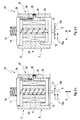
- a first embodiment of a valve actuator 1 is shown in a schematic cross section.
- the valve actuator 1 is designed with a rotationally symmetric shape.
- different designs are equally possible.
- the valve actuator 1 comprises a driving section 2 for directly driving a valve stem 5, which can connect to a fluid influencing part 6 (see Figs. 4 and 6 ), e.g. for moving a poppet head 7 of a poppet valve 8.
- a fluid influencing part 6 see Figs. 4 and 6
- an actuated valve 21 can be realized.
- both the driving section 2, as well as the loading section 3 of the valve actuator 1 are electrically driven. More detailed the respective electric current for actuating the driving section 2 and the loading section 3 is fed into an appropriate electrical coil 9, 10 (driving electrical coil 9 and loading electrical coil 10) of the driving section 2 and the loading section 3, respectively. Within the electrical coil 9, 10, a magnetic field is generated, which is acting on an axially movable disc 11, 12 (driving disc 11 and loading disc 12) of the driving section 2 and the loading section 3, respectively. If an electric current is applied to one or both of the electrical coils 9, 10, the respective axially, movable disc 11, 12 experiences an attractive force towards the electrical coil 9, 10, due to the magnetic field generated by the electrical coil 9, 10.
- the axially movable disc 11 of the driving section 2 is fixedly attached to the valve stem 5. Therefore, the valve stem 5 and the driving disc 11 of the driving section 2 always move together. Contrary to this, the axially movable loading disc 12 of the loading section 3 is slidingly movably connected to the valve stem 5. In other words, a hole 13 is provided in the loading disc 12 so that the valve stem 5 and the loading disc 12 can move freely against each other in an actual direction A.
- the energy storage spring 4 is designed as a coil spring, made of flexible steel material.
- a reopening spring 14 is provided, which is connected to the driving disc 11.
- the reopening spring 14 generates a biasing force, pushing the driving disc 11, and hence the valve stem 5, in the direction of a lower position. If the valve actuator 1 is connected to a poppet valve 8 as seen in Fig. 4 , this corresponds to an open position of the poppet valve 8. Depending on the actual use of the valve actuator 1, it is also possible that the reopening spring 14 can be omitted.
- Fig. 1 the position of the valve stem 5 can be particularly seen from the arrows 15, drawn at the lower end of the valve stem 5.
- the left arrows 15a on the left side of the valve stem 5 indicate the upper and the lower position of the valve stem 5, while the right arrow 15b on the right side indicates the actual position of the valve stem 5. If the valve actuator 1 is connected to a poppet valve 8, similar to the situation shown in Fig. 4 , this would correspond to an open position of the poppet valve 8.
- the valve actuator 1 is in its first position, in which the driving section 2 and the valve stem 5 are in their lower position.
- the driving section 2 is in the lower position, although its electrical coil 9 (driving electrical coil 9) is switched off (no electric current going through driving electrical coil 9). This is because of the biasing force of the reopening spring 14 and presumably due to fluid forces, generated by the fluid flowing through a valve 8, which is connected to the valve actuator 1.
- the loading electrical coil 10 of the loading section 3 is switched off as well (no electric current going through loading electrical coil 10). Therefore, the loading disc 12 of the loading section 3 will be pushed into its lower position under the influence of the energy storage spring 4.
- the movement of the loading disc 12 is limited by an appropriate means, for example by a limiting projection (not shown), which can be provided on the valve stem 5 and/or on the body of the valve actuator 1.
- Fig. 1b the loading phase of the valve actuator 1 is shown.
- the valve stem 5 of the valve actuator 1 will remain in its lower position, so that a poppet head 7 of a poppet valve 8 (see Figs. 4 and 6 ) will remain in its open position.
- the variation of the volume of the pumping chamber 18 is performed by a piston 19, which is moved back and forth by interaction with a crankshaft 20.
- the actuated valve 21 may remain in its open position even during an upward stroke of the piston 19, i.e. during a contraction phase of the pumping chamber 18. If the actuated valve 21 will remain open for the entire cycle, an idle mode of the synthetically commutated hydraulic machine 16 is achieved, in which hydraulic fluid is simply moved back and forth out of the and into the low pressure fluid reservoir 17. If the actuated valve 21 is closed during a middle position of the contracting cycle of the pumping chamber 18, a part stroke mode is achieved, so that the synthetically commutated hydraulic machine 16 runs only at a fraction of its full pumping capability.
- the energy storage spring 4 By the upward movement of the loading disc 12 (wherein the driving disc 11 will remain in its lower position), the energy storage spring 4 will be compressed, thus storing mechanical energy therein.
- an electric current is also applied to the driving electrical coil 9 of the driving section 2. This way the driving disc 11 will be held in place. Due to the nature of the attractive force of the magnetic fields, generated by the driving electrical coil 9 and the loading electrical coil 10, a relatively small electric current is needed for holding the-respective disc 11, 12 in a latched position, whereas a relatively large electric current is needed for accelerating the respective disc 11, 12 out of its distant position towards its latched position. This is indicated by the different size of the electrical flashes, drawn in Fig. 1b . A reduced electric current can be realized by pulse width modulation, which is indicated by the letters PWM in Fig. 1b (as well as in Figs. 1c and d ).
- Fig. 1c the valve actuator 1 is shown in a state, in which both the driving disc 11 and the loading disc 12 are in their latched position, i.e. the driving disc 11 is in its lower position while the loading disc 12 is in its upper position. Since both disc 11,12 are in their latched positions, the electric current through both electrical coils 9,10 can be reduced to a "latching level", in which the attractive force is just enough to hold the respective disc 11,12 in its latched position. This way electrical energy can be saved which is clearly of advantage. It has to be noted that the valve actuator 1 will usually stay in the position, shown in Fig. 1c for an elongated time. Therefore, the savings in electrical energy can be substantial. The reduction in electrical current can be done by pulse width modulation, as already mentioned.
- the driving electrical coil 9 can be simply switched off (see Fig. 1d ).
- the electric current through the loading coil 10, however, will remain at its "latched level". This way, the mechanical energy, stored in the energy storage spring 4 will force the driving disc 11, and therefore the valve stem 5, into its upper position.
- Fig. 1d the result of this upward movement of the driving disk 11 is shown.
- the poppet valve 8 will be closed, if the valve actuator 1 is connected to a fluid influencing part 6, as shown in Fig. 4 or Fig. 6 .
- the loading disc 12 will return to its lower position. This way, the tension of the energy storage spring 4 will be lowered to an extent, that the biasing force of the reopening spring 14 will overweigh the remaining force of the energy storage spring 4. Therefore, the driving disc 11, and hence the valve stem 5 will return to its lower position. This way the valve actuator will return to its position, as seen in Fig. 1a , thus completing the actuation cycle.
- a modified valve actuator 22 is shown in a schematic cross section. Similar to Fig. 1 , the valve actuator 22 is shown in different positions of its working cycle (see Figs. 2a to 2d ).
- the valve actuator 22 is designed with a single electrical coil 23. This simplifies the design of the valve actuator 22 in certain aspects. In particular, only' a single electrical driving unit for the valve actuator 22 is needed (as compared to the valve actuator 1, shown in Fig. 1 ). Since electronics, capable of controlling large currents is still quite expensive, this can be of a particular advantage. Apart from this, the valve actuator 22 and the valve actuator 1 of Fig. 1 show several similarities. Therefore, identical reference numbers have been used for similar parts.
- the axially movable driving disc 11 is in its lower position (influenced by the reopening spring 14). Also, the axially movable loading disc 12 of the loading section 3 is in its lower position (as influenced by the energy storage spring 4).
- the single electrical coil 23 will be energized (i.e. an electric voltage is supplied to the single electrical coil 23), thus moving the loading disc 12 from its lower position to its upper, latched position.
- the volume of the cavity 24, which is defined by a projection 25 of the loading disc 12 will decrease in size. Hydraulic oil, which is entrapped in this cavity 24, will therefore be pushed out through latch check valve 26, provided within the valve actuator 22.
- the hydraulic oil can be returned to a low pressure fluid reservoir 17, for example.
- the loading disc 12 will remain in its latched position, despite the missing magnetic field. This is due to the cavity 24 and the latch check valve 26: A downward movement of the loading disc 12 would require an influx of hydraulic oil into the cavity 24, which is not (yet) possible.
- the driving disc 11 will be pushed upwards under the influence of the force, generated by the energy storage spring 4. This movement is not hindered by the cavity 24. Furthermore, the driving disc 11 is connected to a pin-like extension, forming a release spool 28 of a release spool valve 27. The release spool valve 27 will establish a fluid connection between a fluid port 29 on the outside of the valve actuator 22, and the cavity 24 within the valve actuator 22. This situation is shown in Fig. 2c , where the driving disc 11 has reached its upper position, while the loading disc 12 is still in its latched position.
- fluid can flow through the fluid port 29 into the cavity 24.
- the fluid port 29 can be connected to a low pressure fluid reservoir 17, for example. Therefore, the loading disc 12 is now free to leave its latched position and return to its lower position, which is shown in Fig. 2d .
- valve actuator 22 will return to its original position, shown in Fig. 2a , thus finishing the actuation cycle.
- FIG. 3 another valve actuator 30 is shown.
- the valve actuator 30 is primarily a modification of the valve actuator 22, shown in Fig. 2 . Therefore, similar parts have been indicated with identical reference numbers.
- Most parts of the valve actuator 30, as well as its working cycle ( Fig. 3a through Fig. 3d ) are similar to the valve actuator 22 of Fig. 2 .
- the latching device 31 for the loading disc 12 is designed in a different way.
- the latching is preformed by a pair of toggles 32 (of course, a different number of toggles 32 can be used as well).
- the toggles 32 are pushed into an inwardly directed, latching position (see Fig. 3b ) under the influence of biasing springs 33.
- the opening movement of the toggles 32 is performed by an unlatching disc 34, which is fixedly arranged on the valve stem 5 of the valve actuator 30.
- the unlatching effect of the unlatching disc 34 can be seen in Fig. 3c .
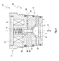
- valve actuator 35 In Fig. 4 , another design of a valve actuator 35 is shown in a schematic illustration.
- valve actuator 35 particularly the loading section 36 is designed differently from the loading sections 3 of the Valve actuators 1, 22, 30 shown in Figs. 1 , 2-and 3 .
- the driving section 2 comprising the driving electrical coil 9 and the axially movable driving disc 11, fixedly connected to the valve stem 5, is similar to the driving section 2 of the valve actuator 1, shown in Fig. 1 .
- similar parts are indicated by identical reference numbers.
- valve actuator 35 shown in Fig. 4 , is connected to a fluid influencing part 6, comprising a poppet valve 8 with a poppet head 7 that can be moved in an axial direction A in a way that the poppet head 7 can either contact valve seat 37 (thus closing the poppet valve 8), or that it can be placed distant from the valve seat 37, thus opening the poppet valve 8.
- fluid influencing part 6 can be connected to any of the described valve actuators 1, 22, 29, 35 and/or that the presently shown valve actuator 35 (or any of the described valve actuators 1, 22, 29, 35) can be connected to a fluid working machine 16, as shown in Fig. 6 .
- the loading disc 38 which is contacting the energy storage spring 4 (which itself contacts the driving disc 11 of the driving section 2) is driven by hydraulic fluid forces. Therefore, the driving section 36 further comprises a fluid cavity 39, which is fluidly connected to a control fluid port 40 via fluid channel 41. By either feeding hydraulic fluid into the fluid cavity 39 or by releasing hydraulic fluid out of the fluid cavity 39, the position of the loading disc 38 can be changed, thus loading and unloading the energy storage spring 4.
- the control of the hydraulic fluid, entering the fluid cavity 39 via control fluid port 40 and fluid channel 41, can be performed by a commutator disc 42, as schematically drawn in Fig. 5 .
- the commutator disc 42 can be mechanically connected to the crankshaft 20 of a synthetically commutated hydraulic machine 16 (see Fig. 6 ) in a way that it is moving off-axis of a turning axis 43 together with the camshaft 20.
- the commutator disc 42 is drawn in the top dead center position of the piston 19 of the synthetically commutated hydraulic machine 16.
- the commutator disc 42 is provided with two internal chambers 44 and 45, namely a charging chamber 44 and a releasing chamber 45.
- the control fluid port 40 is either connected to the charging chamber 44 or the releasing chamber 45 of the commutator disc 42.
- the charging chamber 44 of the commutator disc 42 has an extension (in particular a radial extension), so that a pilot fluid port 46, connected to a increased pressure reservoir, is also fluidly connected to the charging chamber 44. Therefore, an elevated fluid pressure will be transmitted from the pilot fluid port 46 to the fluid cavity 39 via charging chamber 44, control fluid port 40 and fluid channel 41.
- pilot valves are used to apply hydraulic preload pressure to the control port of the valve during the time interval the control unit might want to fire (close) the valve.
- mechanically preloading with e.g. a cam mechanism is possible as yet another possibility.
- the dimensions of the releasing chamber 45 (in particular its radial dimension) is chosen in a way that control fluid port 40 will be connected to the open “outside” via the outside opening 47, if the commutator disc 42 is in an angular position in which the control fluid port fluidly connects to the releasing chamber 45.
- the crankshaft case 48 of the crankshaft 20 of the synthetically commutated hydraulic machine 16 is meant.
- Such a crankshaft case 48 is usually connected to a low pressure fluid reservoir 17 since the crankshaft case 48 collects leakage oil from the pistons 19, for example.
- the outside opening 47 is designed in a way that essentially no wall is provided between the release chamber 45 and the crankshaft case 48.
- valve actuator 1 within a schematically drawn synthetically commutated hydraulic machine 16 is depicted. It has to be understood, however, that for the synthetically commutated hydraulic machine, all of the presented valve actuators 1, 22, 29, 35 can be used. Of course, even more valve actuators, in particular valve actuators, which are modifications from the presently presented valve actuators 1, 22, 29, 35 can be used for this purpose.
Landscapes
- Engineering & Computer Science (AREA)
- General Engineering & Computer Science (AREA)
- Mechanical Engineering (AREA)
- Physics & Mathematics (AREA)
- Electromagnetism (AREA)
- Magnetically Actuated Valves (AREA)
- Valve Device For Special Equipments (AREA)
Priority Applications (2)
| Application Number | Priority Date | Filing Date | Title |
|---|---|---|---|
| EP09000075.3A EP2206940B1 (de) | 2009-01-07 | 2009-01-07 | Ventilaktor |
| EP09002322.7A EP2211078B1 (de) | 2009-01-07 | 2009-02-19 | Ventilaktor |
Applications Claiming Priority (1)
| Application Number | Priority Date | Filing Date | Title |
|---|---|---|---|
| EP09000075.3A EP2206940B1 (de) | 2009-01-07 | 2009-01-07 | Ventilaktor |
Publications (2)
| Publication Number | Publication Date |
|---|---|
| EP2206940A1 true EP2206940A1 (de) | 2010-07-14 |
| EP2206940B1 EP2206940B1 (de) | 2017-06-21 |
Family
ID=40732247
Family Applications (1)
| Application Number | Title | Priority Date | Filing Date |
|---|---|---|---|
| EP09000075.3A Active EP2206940B1 (de) | 2009-01-07 | 2009-01-07 | Ventilaktor |
Country Status (1)
| Country | Link |
|---|---|
| EP (1) | EP2206940B1 (de) |
Cited By (2)
| Publication number | Priority date | Publication date | Assignee | Title |
|---|---|---|---|---|
| EP3211395A1 (de) | 2016-02-26 | 2017-08-30 | Mitsubishi Heavy Industries, Ltd. | Verfahren und system zur diagnose einer hydraulischen maschine, hydraulische maschine und leistungserzeugungsvorrichtung für erneuerbare energie |
| WO2018146601A1 (en) * | 2017-02-08 | 2018-08-16 | Bishoff Mark Eugene | A shut-off valve for a fluid circuit and method for operating the same |
Families Citing this family (1)
| Publication number | Priority date | Publication date | Assignee | Title |
|---|---|---|---|---|
| US10808858B2 (en) | 2017-10-17 | 2020-10-20 | Automotive Technologies International, Inc. | High speed valve |
Citations (4)
| Publication number | Priority date | Publication date | Assignee | Title |
|---|---|---|---|---|
| US6315265B1 (en) | 1999-04-14 | 2001-11-13 | Wisconsin Alumni Research Foundation | Variable valve timing actuator |
| US20050067596A1 (en) | 2001-12-17 | 2005-03-31 | Rampen William H S | Annular valve |
| US7300260B1 (en) | 2003-10-31 | 2007-11-27 | Sauer-Danfoss Inc. | Special fluids for use in a hydrostatic transmission |
| US20070272890A1 (en) * | 2006-05-26 | 2007-11-29 | Herbert Kopecek | Electromagnetic actuators |
Family Cites Families (1)
| Publication number | Priority date | Publication date | Assignee | Title |
|---|---|---|---|---|
| EP1199501B1 (de) * | 2000-10-20 | 2006-02-15 | Siemens Aktiengesellschaft | Stellantrieb für ein Ventil, insbesondere ein Turbinenventil |
-
2009
- 2009-01-07 EP EP09000075.3A patent/EP2206940B1/de active Active
Patent Citations (4)
| Publication number | Priority date | Publication date | Assignee | Title |
|---|---|---|---|---|
| US6315265B1 (en) | 1999-04-14 | 2001-11-13 | Wisconsin Alumni Research Foundation | Variable valve timing actuator |
| US20050067596A1 (en) | 2001-12-17 | 2005-03-31 | Rampen William H S | Annular valve |
| US7300260B1 (en) | 2003-10-31 | 2007-11-27 | Sauer-Danfoss Inc. | Special fluids for use in a hydrostatic transmission |
| US20070272890A1 (en) * | 2006-05-26 | 2007-11-29 | Herbert Kopecek | Electromagnetic actuators |
Cited By (3)
| Publication number | Priority date | Publication date | Assignee | Title |
|---|---|---|---|---|
| EP3211395A1 (de) | 2016-02-26 | 2017-08-30 | Mitsubishi Heavy Industries, Ltd. | Verfahren und system zur diagnose einer hydraulischen maschine, hydraulische maschine und leistungserzeugungsvorrichtung für erneuerbare energie |
| WO2018146601A1 (en) * | 2017-02-08 | 2018-08-16 | Bishoff Mark Eugene | A shut-off valve for a fluid circuit and method for operating the same |
| US10724652B2 (en) | 2017-02-08 | 2020-07-28 | Mark Eugene BISHOFF | Shut-off valve for a fluid circuit and method for operating the same |
Also Published As
| Publication number | Publication date |
|---|---|
| EP2206940B1 (de) | 2017-06-21 |
Similar Documents
| Publication | Publication Date | Title |
|---|---|---|
| KR101236593B1 (ko) | 유체 작동 기계 | |
| JP5487451B2 (ja) | 内燃エンジンバルブトレイン切替え装置 | |
| EP2182531B1 (de) | Ventilaktuator | |
| KR101215986B1 (ko) | 공압 부스터를 갖는 가변형 밸브 엑츄에이터 | |
| US9201427B2 (en) | Method and device for controlling a valve | |
| EP1893849A2 (de) | Verstellbare betätigungsvorrichtung für ein ventil | |
| US9382885B2 (en) | Fuel injection valve for an internal combustion engine | |
| JPH04232319A (ja) | 非対称双安定液圧作動アクチュエータ機構 | |
| EP2206940B1 (de) | Ventilaktor | |
| EP2206941B1 (de) | Betätigtes Ventil | |
| EP3283737B1 (de) | Pneumatischer aktuator für ein motorventil | |
| US6205964B1 (en) | Damping device for movable masses, preferably for electromagnetic systems | |
| US6857618B2 (en) | Device for controlling a gas exchange valve | |
| EP0548294B1 (de) | Verfahren zur betätigung einer hubventilvorrichtung mit rückgewinnung | |
| US20040149944A1 (en) | Electromechanical valve actuator | |
| KR20210045481A (ko) | 밸브 | |
| EP3283798B1 (de) | Mehrwegeventil sowie aktuator mit solch einem mehrwegeventil | |
| US6675751B1 (en) | Two-mass bi-directional hydraulic damper | |
| WO1999054626A1 (en) | Piezoceramic actuators and actuating system incorporating piezoceramic elements | |
| US6997433B2 (en) | Electronic valve actuator having vibration cancellation | |
| EP2211078B1 (de) | Ventilaktor | |
| EP3901426B1 (de) | Ventiltrieb und motor | |
| CN107288699B (zh) | 一种压电驱动的无凸轮轴气门驱动机构 | |
| EP1843013A2 (de) | Elektrohydraulisches system und Vorrichtung zur variablen Betätigung der Ventile einer Brennkraftmaschine | |
| EP3009656A1 (de) | Flüssigkeitseinspritzventil für einen Verbrennungsmotor und Verfahren zum Betrieb davon |
Legal Events
| Date | Code | Title | Description |
|---|---|---|---|
| PUAI | Public reference made under article 153(3) epc to a published international application that has entered the european phase |
Free format text: ORIGINAL CODE: 0009012 |
|
| AK | Designated contracting states |
Kind code of ref document: A1 Designated state(s): AT BE BG CH CY CZ DE DK EE ES FI FR GB GR HR HU IE IS IT LI LT LU LV MC MK MT NL NO PL PT RO SE SI SK TR |
|
| AX | Request for extension of the european patent |
Extension state: AL BA RS |
|
| 17P | Request for examination filed |
Effective date: 20101229 |
|
| 17Q | First examination report despatched |
Effective date: 20110204 |
|
| AKX | Designation fees paid |
Designated state(s): AT BE BG CH CY CZ DE DK EE ES FI FR GB GR HR HU IE IS IT LI LT LU LV MC MK MT NL NO PL PT RO SE SI SK TR |
|
| RAP1 | Party data changed (applicant data changed or rights of an application transferred) |
Owner name: DANFOSS POWER SOLUTIONS APS |
|
| RIC1 | Information provided on ipc code assigned before grant |
Ipc: F16K 31/06 20060101AFI20160727BHEP Ipc: F01L 9/04 20060101ALN20160727BHEP Ipc: F04B 53/10 20060101ALI20160727BHEP |
|
| RIC1 | Information provided on ipc code assigned before grant |
Ipc: F01L 9/04 20060101ALN20160815BHEP Ipc: F04B 53/10 20060101ALI20160815BHEP Ipc: F16K 31/06 20060101AFI20160815BHEP |
|
| RIC1 | Information provided on ipc code assigned before grant |
Ipc: F16K 31/06 20060101AFI20170224BHEP Ipc: F01L 9/04 20060101ALN20170224BHEP Ipc: F04B 53/10 20060101ALI20170224BHEP |
|
| GRAP | Despatch of communication of intention to grant a patent |
Free format text: ORIGINAL CODE: EPIDOSNIGR1 |
|
| RIC1 | Information provided on ipc code assigned before grant |
Ipc: F04B 53/10 20060101ALI20170330BHEP Ipc: F16K 31/06 20060101AFI20170330BHEP Ipc: F01L 9/04 20060101ALN20170330BHEP |
|
| INTG | Intention to grant announced |
Effective date: 20170410 |
|
| GRAS | Grant fee paid |
Free format text: ORIGINAL CODE: EPIDOSNIGR3 |
|
| GRAA | (expected) grant |
Free format text: ORIGINAL CODE: 0009210 |
|
| AK | Designated contracting states |
Kind code of ref document: B1 Designated state(s): AT BE BG CH CY CZ DE DK EE ES FI FR GB GR HR HU IE IS IT LI LT LU LV MC MK MT NL NO PL PT RO SE SI SK TR |
|
| REG | Reference to a national code |
Ref country code: GB Ref legal event code: FG4D |
|
| REG | Reference to a national code |
Ref country code: CH Ref legal event code: EP |
|
| REG | Reference to a national code |
Ref country code: IE Ref legal event code: FG4D |
|
| REG | Reference to a national code |
Ref country code: AT Ref legal event code: REF Ref document number: 903269 Country of ref document: AT Kind code of ref document: T Effective date: 20170715 |
|
| REG | Reference to a national code |
Ref country code: DE Ref legal event code: R096 Ref document number: 602009046683 Country of ref document: DE |
|
| REG | Reference to a national code |
Ref country code: NL Ref legal event code: MP Effective date: 20170621 |
|
| PG25 | Lapsed in a contracting state [announced via postgrant information from national office to epo] |
Ref country code: LT Free format text: LAPSE BECAUSE OF FAILURE TO SUBMIT A TRANSLATION OF THE DESCRIPTION OR TO PAY THE FEE WITHIN THE PRESCRIBED TIME-LIMIT Effective date: 20170621 Ref country code: HR Free format text: LAPSE BECAUSE OF FAILURE TO SUBMIT A TRANSLATION OF THE DESCRIPTION OR TO PAY THE FEE WITHIN THE PRESCRIBED TIME-LIMIT Effective date: 20170621 Ref country code: GR Free format text: LAPSE BECAUSE OF FAILURE TO SUBMIT A TRANSLATION OF THE DESCRIPTION OR TO PAY THE FEE WITHIN THE PRESCRIBED TIME-LIMIT Effective date: 20170922 Ref country code: FI Free format text: LAPSE BECAUSE OF FAILURE TO SUBMIT A TRANSLATION OF THE DESCRIPTION OR TO PAY THE FEE WITHIN THE PRESCRIBED TIME-LIMIT Effective date: 20170621 Ref country code: NO Free format text: LAPSE BECAUSE OF FAILURE TO SUBMIT A TRANSLATION OF THE DESCRIPTION OR TO PAY THE FEE WITHIN THE PRESCRIBED TIME-LIMIT Effective date: 20170921 |
|
| REG | Reference to a national code |
Ref country code: LT Ref legal event code: MG4D |
|
| REG | Reference to a national code |
Ref country code: AT Ref legal event code: MK05 Ref document number: 903269 Country of ref document: AT Kind code of ref document: T Effective date: 20170621 |
|
| PG25 | Lapsed in a contracting state [announced via postgrant information from national office to epo] |
Ref country code: BG Free format text: LAPSE BECAUSE OF FAILURE TO SUBMIT A TRANSLATION OF THE DESCRIPTION OR TO PAY THE FEE WITHIN THE PRESCRIBED TIME-LIMIT Effective date: 20170921 Ref country code: SE Free format text: LAPSE BECAUSE OF FAILURE TO SUBMIT A TRANSLATION OF THE DESCRIPTION OR TO PAY THE FEE WITHIN THE PRESCRIBED TIME-LIMIT Effective date: 20170621 Ref country code: NL Free format text: LAPSE BECAUSE OF FAILURE TO SUBMIT A TRANSLATION OF THE DESCRIPTION OR TO PAY THE FEE WITHIN THE PRESCRIBED TIME-LIMIT Effective date: 20170621 Ref country code: LV Free format text: LAPSE BECAUSE OF FAILURE TO SUBMIT A TRANSLATION OF THE DESCRIPTION OR TO PAY THE FEE WITHIN THE PRESCRIBED TIME-LIMIT Effective date: 20170621 |
|
| REG | Reference to a national code |
Ref country code: FR Ref legal event code: PLFP Year of fee payment: 10 |
|
| PG25 | Lapsed in a contracting state [announced via postgrant information from national office to epo] |
Ref country code: RO Free format text: LAPSE BECAUSE OF FAILURE TO SUBMIT A TRANSLATION OF THE DESCRIPTION OR TO PAY THE FEE WITHIN THE PRESCRIBED TIME-LIMIT Effective date: 20170621 Ref country code: SK Free format text: LAPSE BECAUSE OF FAILURE TO SUBMIT A TRANSLATION OF THE DESCRIPTION OR TO PAY THE FEE WITHIN THE PRESCRIBED TIME-LIMIT Effective date: 20170621 Ref country code: CZ Free format text: LAPSE BECAUSE OF FAILURE TO SUBMIT A TRANSLATION OF THE DESCRIPTION OR TO PAY THE FEE WITHIN THE PRESCRIBED TIME-LIMIT Effective date: 20170621 Ref country code: EE Free format text: LAPSE BECAUSE OF FAILURE TO SUBMIT A TRANSLATION OF THE DESCRIPTION OR TO PAY THE FEE WITHIN THE PRESCRIBED TIME-LIMIT Effective date: 20170621 Ref country code: AT Free format text: LAPSE BECAUSE OF FAILURE TO SUBMIT A TRANSLATION OF THE DESCRIPTION OR TO PAY THE FEE WITHIN THE PRESCRIBED TIME-LIMIT Effective date: 20170621 |
|
| PG25 | Lapsed in a contracting state [announced via postgrant information from national office to epo] |
Ref country code: IT Free format text: LAPSE BECAUSE OF FAILURE TO SUBMIT A TRANSLATION OF THE DESCRIPTION OR TO PAY THE FEE WITHIN THE PRESCRIBED TIME-LIMIT Effective date: 20170621 Ref country code: PL Free format text: LAPSE BECAUSE OF FAILURE TO SUBMIT A TRANSLATION OF THE DESCRIPTION OR TO PAY THE FEE WITHIN THE PRESCRIBED TIME-LIMIT Effective date: 20170621 Ref country code: ES Free format text: LAPSE BECAUSE OF FAILURE TO SUBMIT A TRANSLATION OF THE DESCRIPTION OR TO PAY THE FEE WITHIN THE PRESCRIBED TIME-LIMIT Effective date: 20170621 Ref country code: IS Free format text: LAPSE BECAUSE OF FAILURE TO SUBMIT A TRANSLATION OF THE DESCRIPTION OR TO PAY THE FEE WITHIN THE PRESCRIBED TIME-LIMIT Effective date: 20171021 |
|
| REG | Reference to a national code |
Ref country code: DE Ref legal event code: R097 Ref document number: 602009046683 Country of ref document: DE |
|
| PLBE | No opposition filed within time limit |
Free format text: ORIGINAL CODE: 0009261 |
|
| STAA | Information on the status of an ep patent application or granted ep patent |
Free format text: STATUS: NO OPPOSITION FILED WITHIN TIME LIMIT |
|
| PG25 | Lapsed in a contracting state [announced via postgrant information from national office to epo] |
Ref country code: DK Free format text: LAPSE BECAUSE OF FAILURE TO SUBMIT A TRANSLATION OF THE DESCRIPTION OR TO PAY THE FEE WITHIN THE PRESCRIBED TIME-LIMIT Effective date: 20170621 |
|
| 26N | No opposition filed |
Effective date: 20180322 |
|
| PG25 | Lapsed in a contracting state [announced via postgrant information from national office to epo] |
Ref country code: SI Free format text: LAPSE BECAUSE OF FAILURE TO SUBMIT A TRANSLATION OF THE DESCRIPTION OR TO PAY THE FEE WITHIN THE PRESCRIBED TIME-LIMIT Effective date: 20170621 |
|
| REG | Reference to a national code |
Ref country code: CH Ref legal event code: PL |
|
| PG25 | Lapsed in a contracting state [announced via postgrant information from national office to epo] |
Ref country code: LU Free format text: LAPSE BECAUSE OF NON-PAYMENT OF DUE FEES Effective date: 20180107 |
|
| REG | Reference to a national code |
Ref country code: IE Ref legal event code: MM4A |
|
| REG | Reference to a national code |
Ref country code: BE Ref legal event code: MM Effective date: 20180131 |
|
| PG25 | Lapsed in a contracting state [announced via postgrant information from national office to epo] |
Ref country code: LI Free format text: LAPSE BECAUSE OF NON-PAYMENT OF DUE FEES Effective date: 20180131 Ref country code: CH Free format text: LAPSE BECAUSE OF NON-PAYMENT OF DUE FEES Effective date: 20180131 Ref country code: BE Free format text: LAPSE BECAUSE OF NON-PAYMENT OF DUE FEES Effective date: 20180131 |
|
| PG25 | Lapsed in a contracting state [announced via postgrant information from national office to epo] |
Ref country code: IE Free format text: LAPSE BECAUSE OF NON-PAYMENT OF DUE FEES Effective date: 20180107 |
|
| PG25 | Lapsed in a contracting state [announced via postgrant information from national office to epo] |
Ref country code: MC Free format text: LAPSE BECAUSE OF FAILURE TO SUBMIT A TRANSLATION OF THE DESCRIPTION OR TO PAY THE FEE WITHIN THE PRESCRIBED TIME-LIMIT Effective date: 20170621 |
|
| PG25 | Lapsed in a contracting state [announced via postgrant information from national office to epo] |
Ref country code: MT Free format text: LAPSE BECAUSE OF NON-PAYMENT OF DUE FEES Effective date: 20180107 |
|
| PG25 | Lapsed in a contracting state [announced via postgrant information from national office to epo] |
Ref country code: TR Free format text: LAPSE BECAUSE OF FAILURE TO SUBMIT A TRANSLATION OF THE DESCRIPTION OR TO PAY THE FEE WITHIN THE PRESCRIBED TIME-LIMIT Effective date: 20170621 |
|
| PG25 | Lapsed in a contracting state [announced via postgrant information from national office to epo] |
Ref country code: PT Free format text: LAPSE BECAUSE OF FAILURE TO SUBMIT A TRANSLATION OF THE DESCRIPTION OR TO PAY THE FEE WITHIN THE PRESCRIBED TIME-LIMIT Effective date: 20170621 Ref country code: HU Free format text: LAPSE BECAUSE OF FAILURE TO SUBMIT A TRANSLATION OF THE DESCRIPTION OR TO PAY THE FEE WITHIN THE PRESCRIBED TIME-LIMIT; INVALID AB INITIO Effective date: 20090107 |
|
| PG25 | Lapsed in a contracting state [announced via postgrant information from national office to epo] |
Ref country code: CY Free format text: LAPSE BECAUSE OF FAILURE TO SUBMIT A TRANSLATION OF THE DESCRIPTION OR TO PAY THE FEE WITHIN THE PRESCRIBED TIME-LIMIT Effective date: 20170621 Ref country code: MK Free format text: LAPSE BECAUSE OF NON-PAYMENT OF DUE FEES Effective date: 20170621 |
|
| PGFP | Annual fee paid to national office [announced via postgrant information from national office to epo] |
Ref country code: FR Payment date: 20211224 Year of fee payment: 14 |
|
| PGFP | Annual fee paid to national office [announced via postgrant information from national office to epo] |
Ref country code: DE Payment date: 20211207 Year of fee payment: 14 |
|
| PGFP | Annual fee paid to national office [announced via postgrant information from national office to epo] |
Ref country code: GB Payment date: 20221201 Year of fee payment: 15 |
|
| P01 | Opt-out of the competence of the unified patent court (upc) registered |
Effective date: 20230617 |
|
| REG | Reference to a national code |
Ref country code: DE Ref legal event code: R119 Ref document number: 602009046683 Country of ref document: DE |
|
| PG25 | Lapsed in a contracting state [announced via postgrant information from national office to epo] |
Ref country code: DE Free format text: LAPSE BECAUSE OF NON-PAYMENT OF DUE FEES Effective date: 20230801 |
|
| PG25 | Lapsed in a contracting state [announced via postgrant information from national office to epo] |
Ref country code: FR Free format text: LAPSE BECAUSE OF NON-PAYMENT OF DUE FEES Effective date: 20230131 |