EP2206936A1 - Gear set and nutation gear set - Google Patents
Gear set and nutation gear set Download PDFInfo
- Publication number
- EP2206936A1 EP2206936A1 EP10150538A EP10150538A EP2206936A1 EP 2206936 A1 EP2206936 A1 EP 2206936A1 EP 10150538 A EP10150538 A EP 10150538A EP 10150538 A EP10150538 A EP 10150538A EP 2206936 A1 EP2206936 A1 EP 2206936A1
- Authority
- EP
- European Patent Office
- Prior art keywords
- pin
- gears
- retention
- pair
- axis
- Prior art date
- Legal status (The legal status is an assumption and is not a legal conclusion. Google has not performed a legal analysis and makes no representation as to the accuracy of the status listed.)
- Granted
Links
Images




Classifications
-
- B—PERFORMING OPERATIONS; TRANSPORTING
- B62—LAND VEHICLES FOR TRAVELLING OTHERWISE THAN ON RAILS
- B62D—MOTOR VEHICLES; TRAILERS
- B62D5/00—Power-assisted or power-driven steering
- B62D5/008—Changing the transfer ratio between the steering wheel and the steering gear by variable supply of energy, e.g. by using a superposition gear
-
- F—MECHANICAL ENGINEERING; LIGHTING; HEATING; WEAPONS; BLASTING
- F16—ENGINEERING ELEMENTS AND UNITS; GENERAL MEASURES FOR PRODUCING AND MAINTAINING EFFECTIVE FUNCTIONING OF MACHINES OR INSTALLATIONS; THERMAL INSULATION IN GENERAL
- F16H—GEARING
- F16H1/00—Toothed gearings for conveying rotary motion
- F16H1/28—Toothed gearings for conveying rotary motion with gears having orbital motion
- F16H1/32—Toothed gearings for conveying rotary motion with gears having orbital motion in which the central axis of the gearing lies inside the periphery of an orbital gear
- F16H1/321—Toothed gearings for conveying rotary motion with gears having orbital motion in which the central axis of the gearing lies inside the periphery of an orbital gear the orbital gear being nutating
-
- F—MECHANICAL ENGINEERING; LIGHTING; HEATING; WEAPONS; BLASTING
- F16—ENGINEERING ELEMENTS AND UNITS; GENERAL MEASURES FOR PRODUCING AND MAINTAINING EFFECTIVE FUNCTIONING OF MACHINES OR INSTALLATIONS; THERMAL INSULATION IN GENERAL
- F16H—GEARING
- F16H55/00—Elements with teeth or friction surfaces for conveying motion; Worms, pulleys or sheaves for gearing mechanisms
- F16H55/02—Toothed members; Worms
- F16H55/10—Constructively simple tooth shapes, e.g. shaped as pins, as balls
-
- F—MECHANICAL ENGINEERING; LIGHTING; HEATING; WEAPONS; BLASTING
- F16—ENGINEERING ELEMENTS AND UNITS; GENERAL MEASURES FOR PRODUCING AND MAINTAINING EFFECTIVE FUNCTIONING OF MACHINES OR INSTALLATIONS; THERMAL INSULATION IN GENERAL
- F16H—GEARING
- F16H35/00—Gearings or mechanisms with other special functional features
- F16H35/008—Gearings or mechanisms with other special functional features for variation of rotational phase relationship, e.g. angular relationship between input and output shaft
-
- Y—GENERAL TAGGING OF NEW TECHNOLOGICAL DEVELOPMENTS; GENERAL TAGGING OF CROSS-SECTIONAL TECHNOLOGIES SPANNING OVER SEVERAL SECTIONS OF THE IPC; TECHNICAL SUBJECTS COVERED BY FORMER USPC CROSS-REFERENCE ART COLLECTIONS [XRACs] AND DIGESTS
- Y10—TECHNICAL SUBJECTS COVERED BY FORMER USPC
- Y10T—TECHNICAL SUBJECTS COVERED BY FORMER US CLASSIFICATION
- Y10T74/00—Machine element or mechanism
- Y10T74/19—Gearing
- Y10T74/19642—Directly cooperating gears
- Y10T74/1966—Intersecting axes
Definitions
- the invention relates to a gear set and a nutation gear set.
- gear sets include two bevel gears in mesh with each other (for example, see Japanese Patent Application Publication No. 11-315908 ( JP-A-11-315908 )).
- the first and second gears are in mesh with each other, and the second gear is inclined with respect to the first gear.
- the first gear has a plurality of grooves, and rollers are arranged in the grooves so as to protrude from the grooves. The rollers form semi-cylindrical convex teeth.
- the second gear has a plurality of grooves, and has semi-cylindrical concave teeth. Then, as the first gear rotates, part of the convex teeth of the first gear are in mesh with part of the concave teeth of the second gear. Thus, the first gear rotates the second gear.
- JP-A-11-315908 is not intended to actively press the rollers against the grooves of the first gear, so it is insufficient to prevent the rollers from lifting from the grooves of the first gear or slipping off from the grooves.
- the invention provides a gear set and nutation gear set that are able to prevent lifting or slipping of members that constitute teeth.
- An aspect of the invention provides a gear set that includes: a first gear that is rotatable around a first axis; and a second gear that is rotatable around a second axis inclined with respect to the first axis, and that is in mesh with the first gear so that torque is transmittable.
- One of the first and second gears includes a plurality of retention grooves that are arranged so as to radiate around an axis of the one of the first and second gears and a plurality of pins that are retained in the respective retention grooves and that respectively constitute teeth of the one of the first and second gears.
- the other one of the first and second gears includes a plurality of tooth grooves that are arranged so as to radiate around an axis of the other one of the first and second gears and that are engageable with the pins. A resultant force of forces applied to each pin from the retention groove and the tooth groove urges the pin toward the retention groove.
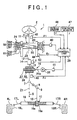
- FIG. 1 is a view that shows the schematic configuration, of a vehicle steering system 1 equipped with a transmission ratio variable mechanism according to a first embodiment of the invention.
- the vehicle steering system 1 applies steering torque, given to a steering member 2 such as a steering wheel, to respective right and left steered wheels 4R and 4L via a steering shaft 3, or the like.
- the vehicle steering system 1 has a variable gear ratio (VGR) function.
- VGR function is able to change a transmission ratio ⁇ 2/ ⁇ 1 that is the ratio of a steered angle ⁇ 2 of each steered wheel to a steering angle ⁇ 1 1 of the steering member 2.
- the vehicle steering system 1 includes the steering member 2 and the steering shaft 3 coupled to the steering member 2.
- the steering shaft 3 includes first to third shafts 11 to 13 that are arranged along the same axis.
- the respective central axes of the first to third shafts 11 to 13 are also the rotation axes of the first to third shafts 11 to 13.
- the steering member 2 is coupled to one end of the first shaft 11 so as to be integrally rotatable.
- the other end of the first shaft 11 is coupled to one end of the second shaft 12 via the transmission ratio variable mechanism 5 so as to be differentially rotatable.
- the second shaft 12 and the third shaft 13 are coupled with each other via a torsion bar 14 so that the second shaft 12 and the third shaft 13 are elastically rotatable relative to each other within a predetermined range and torque transmission is allowed therebetween.
- the third shaft 13 is coupled to the steered wheels 4R and 4L via a universal joint 7, an intermediate shaft 8, a universal joint 9, a steered mechanism 10, and the like.
- the steered mechanism 10 includes a pinion shaft 15 and a rack shaft 16.
- the pinion shaft 15 is coupled to the universal joint 9.
- the rack shaft 16 has a rack 16a that is in mesh with a pinion 15a formed at the distal end of the pinion shaft 15.
- the rack shaft 16 serves as a steered shaft extending in a transverse direction of a vehicle.
- Knuckle arms 18R and 18L are coupled to a pair of respective ends of the rack shaft 16 via tie rods 17R and 17L.
- the transmission ratio variable mechanism 5 is used to change the rotational transmission ratio (transmission ratio ⁇ 2/ ⁇ 1) between the first and second shafts 11 and 12 of the steering shaft 3, and is formed as a nutation gear mechanism.
- the transmission ratio variable mechanism 5 includes an input member 20, an output member 22 and a raceway ring unit 39.
- the input member 20 is provided at the other end of the first shaft 11.
- the output member 22 is provided at one end of the second shaft 12.
- the raceway ring unit 39 serves as an intermediate member interposed between the input member 20 and the output member 22.
- the input member 20 is coupled to the steering member 2 and the first shaft 11 so that torque is transmittable.
- the output member 22 is coupled to the second shaft 12 so that torque is transmittable.
- a first axis Z1 is the central axis and rotation axis of each of the input member 20 and the output member 22.
- the output member 22 is coupled to the steered wheels 4R and 4L via the second shaft 12, the steered mechanism 10, and the like.
- the raceway ring unit 39 includes an inner ring 391, an outer ring 392 and rolling elements 393
- the inner ring 391 serves as a first raceway ring.
- the outer ring 392 serves as a second raceway ring.
- the rolling elements 393 are balls, or the like, interposed between the inner ring 391 and the outer ring 392, and constitute ball bearings.
- the rolling elements 393 may be cylindrical rollers, needle rollers and tapered rollers, other than balls.
- the rolling elements 393 may be arranged in a single row or in a double row. When the rolling elements 393 are arranged in a double row, it is desirable to prevent inclination of the inner ring 391 with respect to the outer ring 392.
- a double row angular bearing may be exemplified as a double row bearing.
- the inner ring 391 couples the input member 20 to the output member 22 so as to be differentially rotatable.
- the inner ring 391 and the outer ring 392 each have a second axis Z2 as a central axis that is inclined with respect to the first axis Z1.
- the second axis Z2 is inclined at a predetermined inclination angle with respect to the first axis Z1.
- the inner ring 391 is rotatably supported by the outer ring 392 via the rolling elements 393, so the inner ring 391 is rotatable around the second axis Z2.
- the inner ring 391 is also rotatable around the first axis Z1 as a transmission ratio variable mechanism motor 23 is driven.
- the transmission ratio variable mechanism motor 23 is an electric motor that serves as an actuator for driving the outer ring 392.
- the inner ring 391 and the outer ring 392 are able to perform Coriolis motion (oscillating motion) around the first axis Z1.
- the transmission ratio variable mechanism motor 23 is arranged radially outward of the raceway ring unit 39, and has the first axis Z1 as a central axis.
- the transmission ratio variable mechanism motor 23 changes the transmission ratio ⁇ 2/ ⁇ 1 by varying the rotational speed of the outer ring 392 around the first axis Z1.
- the transmission ratio variable mechanism motor 23 is, for example, formed of a brushless motor.
- the transmission ratio variable mechanism motor 23 includes a rotor 231 and a stator 232.
- the rotor 231 retains the outer ring 392 of the raceway ring unit 39.
- the stator 232 surrounds the rotor 231 and is fixed to a housing 24 that serves as a steering column.
- the rotor 231 rotates around the first axis Z1.
- the vehicle steering system 1 includes a steering assist force application mechanism 19 for applying steering assist force to the steering shaft 3.
- the steering assist force application mechanism 19 includes the second shaft 12, the third shaft 13, a torque sensor 44, a steering assist motor 25 and a decelerating mechanism 26.
- the second shaft 12 serves as an input shaft coupled to the output member 22 of the transmission ratio variable mechanism 5.
- the third shaft 13 serves as an output shaft coupled to the steered mechanism 10.
- the torque sensor 44 detects torque transmitted between the second shaft 12 and the third shaft 13 and will be described later.
- the steering assist motor 25 serves as a steering assist actuator.
- the decelerating mechanism 26 is interposed between the steering assist motor 25 and the third shaft 13.
- the steering assist motor 25 is formed of an electric motor, such as a brushless motor.
- the output of the steering assist motor 25 is transmitted to the third shaft 13 via the decelerating mechanism 26.
- the decelerating mechanism 26 is, for example, formed of a worm mechanism.
- the decelerating mechanism 26 includes a worm shaft 27 and a worm gear 28.
- the worm shaft 27 serves as a drive gear that is coupled to the output shaft 25a of the steering assist motor 25.
- the worm gear 28 serves as a driven gear that is in mesh with the worm shaft 27 and that is integrally rotatably coupled to the third shaft 13.
- the decelerating mechanism 26 is not limited to the worm gear mechanism; the decelerating mechanism 26 may be another gear mechanism, such as a parallel shaft gear mechanism using a spur gear or a helical gear.
- the transmission ratio variable mechanism 5 and the steering assist force application mechanism 19 are provided for the housing 24.
- the housing 24 is arranged inside a cabin of the vehicle. Note that the housing 24 may be arranged so as to surround the intermediate shaft 8 or may be arranged inside an engine room of the vehicle.
- the transmission ratio variable mechanism motor 23 and the steering assist motor 25 each are controlled to be driven by a control unit 29 that includes a CPU, a RAM and a ROM.
- the control unit 29 is connected to the transmission ratio variable mechanism motor 23 via a drive circuit 40, and is connected to the steering assist motor 25 via a drive circuit 41.
- a steering angle sensor 42, a motor resolver 43, the torque sensor 44, a steered angle sensor 45, a vehicle speed sensor 46 and a yaw rate sensor 47 are connected to the control unit 29.
- the motor resolver 43 serves as a rotation angle detector means for detecting the rotation angle of the transmission ratio variable mechanism motor 23.
- the torque sensor 44 serves as a torque detector.
- a signal indicating the rotation angle of the first shaft 11 is input from the steering angle sensor 42 to the control unit 29 as a value corresponding to a steering angle ⁇ 1 that is an operation amount from the straight-ahead position of the steering member 2.
- a signal indicating the rotation angle ⁇ r of the rotor 231 of the transmission ratio variable mechanism motor 23 is input from the motor resolver 43 to the control unit 29.
- a signal indicating torque applied between the second shaft 12 and the third shaft 13 is input from the torque sensor 44 to the control unit 29 as a value corresponding to a steering torque T applied to the steering member 2.
- a signal indicating the rotation angle of the third shaft 13 is input from the steered angle sensor 45 to the control unit 29 as a value corresponding to a steered angle ⁇ 2.
- a signal indicating the vehicle speed V is input from the vehicle speed sensor 46 to the control unit 29.
- a signal indicating the yaw rate ⁇ of the vehicle is input from the yaw rate sensor 47 to the control unit 29.
- the control unit 29 controls the transmission ratio variable mechanism motor 23 and the steering assist motor 25 for driving on the basis of signals from the sensors 42 to 47, or the like.
- the output of the transmission ratio variable mechanism 5 is transmitted to the steered mechanism 10 via the steering assist force application mechanism 19. More specifically, the steering torque input to the steering member 2 is input to the input member 20 of the transmission ratio variable mechanism 5 via the first shaft 11, and is transmitted from the output member 22 to the second shaft 12 of the steering assist force application mechanism 19. The steering torque transmitted to the second shaft 12 is transmitted to the torsion bar 14 and the third shaft 13, and is transmitted to the steered mechanism 10 together with the output from the steering assist motor 25 via the intermediate shaft 8, or the like.
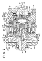
- FIG. 2 is a cross-sectional view that shows the specific configuration of a relevant portion of FIG. 1 .
- the housing 24 is, for example, made by forming metal, such as aluminum alloy, into a cylindrical shape.
- the housing 24 includes first to third housings 51 to 53.
- First to seventh bearings 31 to 37 are accommodated in the housing 24.
- the first to fifth bearings 31 to 35 and the seventh bearing 37 each are a rolling bearing, such as an angular ball bearing.
- the sixth bearing 36 is a rolling bearing, such as a needle roller bearing.
- the first housing 51 has a cylindrical shape.
- the first housing 51 constitutes a differential mechanism housing that accommodates the transmission ratio variable mechanism 5 serving as a differential mechanism.
- the first housing 51 also constitutes a motor housing that accommodates the transmission ratio variable mechanism motor 23.
- One end of the first housing 51 is covered with an end wall member 54.
- One end of the first housing 51 and the end wall member 54 are fixed to each other using a fastening member 55, such as a bolt.
- An annular protrusion 57 of one end of the second housing 52 is fitted to an inner peripheral surface 56 of the other end of the first housing 51.
- These first and second housings 51 and 52 are fixed to each other using a fastening member (not shown), such as a bolt.
- the second housing 52 has a cylindrical shape.
- the second housing 52 constitutes a sensor housing and a resolver housing.
- the sensor housing accommodates the torque sensor 44.
- the resolver housing accommodates the motor resolver 43.
- An inner peripheral surface 60 of one end of the third housing 53 is fitted to an outer peripheral surface 59 of the other end of the second housing 52.
- the third housing 53 has a cylindrical shape.
- the third housing 53 constitutes a decelerating mechanism housing that accommodates the decelerating mechanism 26.
- An end wall portion 61 is provided at the other end of the third housing 53.
- the end wall portion 61 has an annular shape, and covers the other end of the third housing 53.
- FIG. 3 is an enlarged view of the transmission ratio variable mechanism 5 of FIG. 2 and its surroundings.
- the input member 20 and output member 22 of the transmission ratio variable mechanism 5 and the inner ring 391 of the raceway ring unit 39 each have an annular shape.
- the input member 20 is formed as a first gear.
- the input member 20 includes an input member body 201, a cylindrical body 202, a plurality of pins 77, an inner retainer 75 and an outer retainer 76.
- the cylindrical member 202 is arranged radially inward of the input member body 201 and is integrally rotatable with the input member body 201.
- the plurality of pins 77 are retained by the input member body 201.
- the inner retainer 75 and the outer retainer 76 retain the plurality of pins 77 by the input member body 201.
- the input member body 201 and the cylindrical member 202 are integrally formed using a single material.
- the other end of the first shaft 11 is inserted through an insertion hole 202a of the cylindrical member 202.
- the other end of the first shaft 11 that serves as the input shaft of the transmission ratio variable mechanism 5 is coupled to the cylindrical member 202 by, for example, serration engagement so that torque is transmittable.
- the output member 22 is formed as a first gear.
- the output member 22 includes an output member body 221, a cylindrical member 222, a plurality of pins 87, an inner retainer 85 and an outer retainer 86.
- the cylindrical member 222 is arranged radially inward of the output member body 221 and is integrally rotatable with the output member body 221.
- the plurality of pins 87 are retained by the output member body 221.
- the inner retainer 85 and the outer retainer 86 retain the plurality of pins 87 by the output member body 221.
- the output member body 221 and the cylindrical member 222 are integrally formed using a single material.
- One end of the second shaft 12 is inserted through an insertion hole 222a of the cylindrical member 222 of the output member 22.
- An intermediate portion of the second shaft 12 that serves as the output shaft of the transmission ratio variable mechanism 5 is coupled to the output member 22 by, for example, serration engagement so that torque is transmittable.
- the inner ring 391 of the raceway ring unit 39 is all integrally formed using a single member, and is arranged between the input member 20 and the output member 22.
- the inner ring 391 is formed as a second gear that is paired with the input member 20 serving as the first gear, and is formed as a second gear that is paired with the output member 22 serving as the first gear.
- a first end 391a of the inner ring 391 is formed as a gear element of the second gear
- a second end 391b of the inner ring 391 is formed as a gear element of the second gear.
- the first and second ends 391a and 391b have the common axis, and are integrally rotatable around the second axis Z2 serving as the common axis.
- the first gear set 78 is a bevel gear set.
- the second gear set 88 is a bevel gear set.
- the first gear set 78 and the second gear set 88 form a nutation gear set 84.
- the input member 20 and output member 22 of the nutation gear set have the common first axis Z1, and are arranged on opposite sides of the first end 391a and second end 391b of the inner ring 391.
- the outer ring 392 is fixedly press-fitted into an inclined hole 63 that is formed on the inner periphery of the rotor 23 of the transmission ratio variable mechanism motor 23.
- the outer ring 392 integrally rotates with the rotor 231 around the first axis Z1.
- the raceway ring unit 39 performs Coriolis motion.
- the outer ring 392 may couple the input member 20 to the output member 22 so as to be differentially rotatable, and the inner ring 391 may be integrally rotatably coupled to the rotor 231 of the transmission ratio variable mechanism motor 23.
- the raceway ring unit 39 is of an inner ring support type.
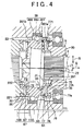
- FIG. 4 is an enlarged view of a relevant portion of the transmission ratio variable mechanism 5 of FIG 3 .
- an end surface facing the input member 20 is defined as a first end surface 71.
- an end surface facing the output member 22 is defined as a second end surface 72.
- the input member 20 and the first end 391a of the inner ring 391 have first concave convex engaging portions 64. This allows torque transmission between the input member 20 and the first end 391a.
- the second end 391b of the inner ring 391 and the output member 22 have second concave convex engaging portions 67. This allows torque transmission between the second end 391b and the output member 22.
- FIG. 5 is a perspective view of a relevant portion of the first concave convex engaging portions 64.
- a torque transmitting surface 70 that serves as one end surface of the input member body 201 and the first end surface 71 of the first end 391a face each other in an axial direction S of the steering shaft 3 (hereinafter, simply referred to as axial direction S).
- the first concave convex engaging portions 64 engage the torque transmitting surface 70 with the first end surface 71 so that torque is transmittable.
- the first concave convex engaging portions 64 include a plurality of retention grooves 79, the plurality of pins 77 and a plurality of tooth grooves 80.
- the plurality of retention grooves 79 are formed on the torque transmitting surface 70.
- the plurality of pins 77 are retained in the respective retention grooves 79.
- the plurality of tooth grooves 80 are formed on the first end surface 71 of the first end 391a of the inner ring 391 and engage with the pins 77.
- the input member 20 constitutes one of the first and second gears, and has the retention grooves 79 and the pins 77.
- the inner ring 391 constitutes the other one of the first and second gears, and has the tooth grooves 80.
- the input member 20 has the retention grooves 79 and the pins 77, and the first end 391a of the inner ring 391 has the tooth grooves 80; however, the configuration is not limited to this embodiment. Instead, it is also applicable that the first end 391a of the inner ring 391 has the retention grooves 79 and the pins 77 and the input member body 201 has the tooth grooves 80.
- the input member 20 is the other one of the first and second gears, and the inner ring 391 is one of the first and second gears.
- the retention grooves 79, the pins 77 and the tooth grooves 80 are arranged at equiangular intervals over the respective entire regions of the corresponding torque transmitting surface 70 and first end surface 71 in the circumferential direction.
- the pins 77 are used for forming teeth 81 of the input member 20, and are needle rollers each having, for example, a cylindrical shape. These pins 77 are arranged so as to radiate around the first axis Z1. Half of each pin 77 protrudes from a corresponding one of the retention grooves 79 to have a semi-spherical shape in cross section. The protruded half serves as the tooth 81 of the input member 20. Outer ends 77a of the pins 77 in the radial direction R1 of the input member 20 are collectively retained by the annular outer retainer 76. Inner ends 77b of the pins 77 in the radial direction R1 of the input member 20 are collectively retained by the annular inner retainer 75.
- the pins 77 are mounted on the input member body 201 by these outer retainer 76 and inner retainer 75.
- the outer retainer 76 and the inner retainer 75 each are made of an elastic member, such as synthetic resin.
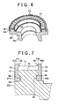
- FIG. 6 is a perspective cross-sectional view that shows part of the input member 20.
- FIG. 7 is an enlarged cross-sectional view of a relevant portion of FIG 6 .
- the outer retainer 76 has an annular body 91.
- One end 91a of the body 91 in the axial direction has an annular protrusion 92 that protrudes radially inward of the body 91.
- the other end 91b of the body 91 in the axial direction has an annular engaging protrusion 93 that protrudes radially inward of the body 91.
- the outer ends 77a of the pins 77 are held and retained by the annular protrusion 92 and the retention grooves 79 of the input member body 201.
- the engaging protrusion 93 is engaged with an engaging portion 94 that is an annular recess formed on an outer periphery of the input member body 201.
- the inner retainer 75 has an annular body 95.
- One end 95a of the body 95 in the axial direction has an annular protrusion 96 that protrudes radially outward of the body 95.
- the other end 95b of the body 95 in the axial direction has an annular engaging protrusion 97 that protrudes radially outward of the body 95.
- the inner ends 77b of the pins 77 are held and retained by the annular protrusion 96 and the retention grooves 79 of the input member body 201.
- the engaging protrusion 97 is engaged with an engaging portion 98 that is an annular recess formed on an inner periphery of the input member body 201.
- the retention grooves 79 are formed in a long slender shape so as to radiate around the first axis Z1.
- the retention grooves 79 extend over the entire region of the torque transmitting surface 70 in the radial direction of the input member 20, and are arranged at equiangular intervals in the circumferential direction of the input member body 201.
- the number of the retention grooves 79 is equal to the number of the pins 77.
- the pins 77 are retained in the retention grooves 79. Note that FIG. 5 does not show the inner retainer 75 or the outer retainer 76.
- the tooth grooves 80 are formed in a long slender shape so as to radiate around the second axis Z2.
- the tooth grooves 80 extend over the entire region of the first end 391a in the radial direction of the inner ring 391, and are arranged at equiangular intervals in the circumferential direction of the first end 391a.
- the number of the tooth grooves 80 is equal to the number of the pins 77 or is different from the number of the pins 77. Depending on a difference between the number of the pins 77 and the number of the tooth grooves 80, it is possible to change the speed between the input member body 201 and the inner ring 391.
- the second axis Z2 of the inner ring 391 is inclined by a predetermined angle ⁇ with respect to the first axis Z1 of the input member 20.
- part of the teeth 81 and part of the tooth grooves 80 are in mesh with each other.
- FIG. 8 is a cross-sectional view of a relevant portion, taken along the line VIII-VIII in FIG. 4 .
- FIG. 8 shows a cross section perpendicular to the longitudinal direction of the pin 77 (pin 771) that is in mesh with the tooth groove 80.
- the cross section perpendicular to the pin 771 is used as a reference.
- one of the features of the present embodiment is that a resultant force F1 + F2 of a force F1 applied to the pin 77 from the retention groove 79 and a force F2 applied to the pin 77 from the tooth groove 80 urges the pin 77 toward a bottom 79a of the retention groove 79 between the bottom 79a of the retention groove 79 and a bottom 80a of the tooth groove 80.
- the cross section of an inner surface 79b of the retention groove 79 of the input member body 201 has a so-called Gothic arch shape, so the bottom 79a has a sharp shape.
- the shape of the cross section of the inner surface 79b is the same over the entire region of the retention groove 79 in the longitudinal direction.
- the inner surface 79b has a pair of first portions 79c and 79d that are located on opposite sides of the bottom 79a of the retention groove 79 and that are arranged in the circumferential direction G of the input member 20.
- the first portion 79c is a circular arc surface having a relatively smaller predetermined curvature radius U1.
- the first portion 79d and the first portion 79c have symmetrical shapes.
- the first portion 79d is a circular arc surface having the same curvature radius U1 as that of the first portion 79c.
- the center of curvature 79e of the first portion 79c and the center of curvature 79f of the first portion 79d are offset from each other in the circumferential direction G
- the cross section of an inner surface 80b of the tooth groove 80 formed on the first end 391a of the inner ring 391 has a so-called Gothic arch shape, so the bottom 80a has a sharp shape.
- the shape of the cross section of the inner surface 80b is the same over the entire region of the tooth groove 80 in the longitudinal direction.
- the inner surface 80b has a pair of second portions 80c and 80d that are located on opposite sides of the bottom 80a of the tooth groove 80 and that are arranged in the circumferential direction of the inner ring 391.
- the second portion 80c is a circular arc surface having a relatively large predetermined curvature radius U2.
- the second portion 80d and the second portion 80c have symmetrical shapes.
- the second portion 80d is a circular arc surface having the same curvature radius U2 as that of the second portion 80c.
- the center of curvature 80e of the second portion 80c and the center of curvature 80f of the second portion 80d are offset from each other in the circumferential direction of the inner ring 391.
- the outer peripheral surface 77c of the pin 77 and the pair of first portions 79c and 79d of the retention groove 79 are in contact with each other at corresponding first contact points 99c and 99d (contact lines).
- the outer peripheral surface 77c of the pin 77 and the pair of second portions 80c and 80d of the tooth groove 80 are in contact with each other at corresponding second contact points 100c and 100d (contact lines). That is, the pin 77 is in contact with the retention groove 79 and the tooth groove 80 at four contact points.
- the first portion 79c of the retention groove 79 and the second portion 80c of the tooth groove 80 face each other via the central axis J1 of the pin 77.
- the first portion 79c of the retention groove 79 makes a first contact angle ⁇ with the pin 77 at the first contact point 99c.
- the first contact angle ⁇ is an angle made between a reference plane 101 and the line of action of the first force F1.
- the reference plane 101 includes the central axis J1 of the pin 77 and the first axis Z1.
- the first force F1 serves as a force applied from the first portion 79c of the retention groove 79 to the first contact point 99c of the pin 77.
- the second portion 80c of the tooth groove 80 makes a second contact angle ⁇ with the pin 77 at the second contact point 100c.
- the second contact angle ⁇ is an angle made between the reference plane 101 and the line of action of the second force F2.
- the second force F2 serves as a force applied from the second portion 80c of the tooth groove 80 to the second contact point 100c of the pin 77.
- the curvature radius U1 of the first portion 79c of the retention groove 79 is relatively small, and the curvature radius U2 of the second portion 80c of the tooth groove 80 is relatively large, so the second contact angle ⁇ is relatively small and the first contact angle ⁇ is relatively large ( ⁇ ⁇ ⁇ ).
- a component F1y of the first force F1 in a direction Y parallel to the reference plane 101 and in a direction Y1 from the retention groove 79 toward the tooth groove 80 is relatively small.
- a component F2y of the second force F2 in the direction Y parallel to the reference plane 101 and in a direction Y2 from the tooth groove 80 toward the retention groove 79 is relatively large.
- the sum F1y + F2y of the component F1y of the first force F1 and the component F2y of the second force F2, parallel to the reference plane 101 is directed in the direction Y2 from the tooth groove 80 toward the retention groove 79 in the direction Y parallel to the reference plane 101, and acts to urge the pin 77 toward the bottom 79 of the retention groove 79.
- first portion 79d of the retention groove 79 and the first portion 79c have symmetrical shapes
- second portion 80d of the tooth groove 80 and the second portion 80c have symmetrical shapes.
- FIG 9 is a cross-sectional view taken along the same line as FIG 8 , illustrating the moment applied to the pin 77.
- another feature of the present embodiment is that, in order to further reliably prevent the pin 77 from slipping off from the retention groove 79, between a first moment M1 and a second moment M2 around the first contact point 99c, the first moment M1 is larger than the second moment M2.
- the first moment M1 is a moment that the second force F2 applied to the pin 77 from the second portion 80c of the inner surface 80b of the tooth groove 80 rotates the pin 77 in one direction H1 around the first contact point 99c.
- the second moment M2 is a moment that a frictional force F3 of the pin 77 against the first portion 80c of the inner surface 80b of the tooth groove 80 rotates the pin 77 in the other direction H2 around the first contact point 99c.
- the pin 77 is urged toward the bottom 79a of the retention groove 79, and it is possible to further reliably prevent the pin 77 from slipping off from the retention groove 79.
- the line segment that connects the first contact point 99c to the second contact point 100c is a line segment AB
- the line segment that connects the first contact point 99c to the central axis J1 of the pin 77 is a line segment AO
- the line segment that connects the second contact point 100c to the central axis J1 of the pin 77 is a line segment BO
- a triangle OAB is an isosceles triangle such that the length of the line segment AO and the length of the line segment BO each are equal to the radius of the pin 77.
- an angle OAB and an angle OBA each are a predetermined angle ⁇ .
- an inclination angle made between the tangent B1 and the straight line B2 is the predetermined angle ⁇ .
- an angle made between the line segment BO and a portion of the straight line B2 extending from the point B toward the retention groove 79 is (90- ⁇ )°.
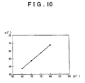
- the first contact angle ⁇ and the second contact angle ⁇ may be, for example, set so as to satisfy the relationship shown in the graph of FIG. 10 .
- the first contact angle ⁇ is larger the more desirable.
- the first contact angle ⁇ is, for example, set at about 81° ⁇ 2°.
- the second contact angle ⁇ is, for example, set at about 66.5° ⁇ 2° in terms of prevention of slipping of the pin 77.
- the above ⁇ 2° is a dimensional tolerance.
- first portion 79d of the retention groove 79 and the first portion 79c have symmetrical shapes
- second portion 80d of the tooth groove 80 and the second portion 80c have symmetrical shapes.
- the torque transmitting surface 73 that serves as one end surface of the output member body 221 and the second end surface 72 of the inner ring 391 face each other in the axial direction S, and the second concave convex engaging portions 67 engage the torque transmitting surface 73 with the second end surface 72 so that torque is transmittable.
- the second concave convex engaging portions 67 include a plurality of retention grooves 109, a plurality of pins 87 and a plurality of tooth grooves 110.
- the plurality of retention grooves 109 are formed on the torque transmitting surface 73.
- the plurality of pins 87 are retained in the respective retention grooves 109.
- the plurality of tooth grooves 110 are formed on the second end surface 72 of the second end 391b of the inner ring 391 and engage with the pins 87.
- the output member 22 constitutes one of the first and second gears, and has the retention grooves 109 and the pins 87.
- the inner ring 391 constitutes the other one of the first and second gears, and has the tooth grooves 110.
- the output member 22 has the retention grooves 109 and the pins 87, and the second end 391b of the inner ring 391 has the tooth grooves 110; however, the configuration is not limited to this embodiment. Instead, it is also applicable that the second end 391b of the inner ring 391 has the retention grooves 109 and the pins 87 and the output member body 221 has the tooth grooves 110.
- the output member 22 is the other one of the first and second gears, and the inner ring 391 is one of the first and second gears.
- the retention grooves 109 and pins 87 of the second concave convex engaging portions 67 have similar configuration to the retention grooves 79 and pins 77 of the first concave convex engaging portions 64.
- the tooth grooves 110 of the second concave convex engaging portions 67 have similar configuration to the tooth grooves 80 of the first concave convex engaging portions 64. Therefore, the detailed description of the second concave convex engaging portions 67 is omitted.
- the inner retainer 85 and the outer retainer 86 for retaining the pins 87 of the second concave convex engaging portions 67 are provided. These retainers 85 and 86 have similar configurations to the corresponding inner retainer 75 and outer retainer 76, so the detailed description thereof is omitted.
- the rotor 231 of the transmission ratio variable mechanism motor 23 includes a cylindrical rotor core 112 and a permanent magnet 113.
- the rotor core 112 extends in the axial direction S.
- the permanent magnet 113 is fixed to an outer peripheral surface of the rotor core 112.
- the rotor core 112 that supports the outer ring 392 of the raceway ring unit 39 rotatably supports the cylindrical member 202 of the input member 20 via a first bearing 31, and rotatably supports the cylindrical member 222 of the output member 22 via a third bearing 33.
- the rotor core 112 is supported at both ends by second and fourth bearings 32 and 34 that are located on opposite sides of the first and third bearings 31 and 33 in the axial direction S.
- the second bearing 32 is held in an annular protrusion 114 that is formed on an inner peripheral portion of one end of the first housing 51.
- the fourth bearing 34 is held on an annular extending portion 115 formed on an inner peripheral portion of the other end of the second housing 52.
- the annular extending portion 115 has a cylindrical shape that extends from a partition wall portion 116 provided at the other end of the second housing 52 toward the one direction S1 in the axial direction S, and is inserted in the rotor core 112.
- the stator 232 of the transmission ratio variable mechanism motor 23 is fixed to the inner peripheral surface of the first housing 51 by shrinkage fitting, or the like, and surrounds the permanent magnet 113 of the rotor 231.
- the motor resolver 43 includes a resolver rotor 117 and a resolver stator 118.
- the resolver rotor 117 is fixed to the outer peripheral surface of the other end of the rotor core 112.
- the resolver stator 118 is fixed to the inner peripheral surface of the second housing 52.
- the torque sensor 44 is arranged radially inward of the rotor core 112 of the transmission ratio variable mechanism motor 23.
- a fifth bearing 35 is arranged on the other side S2 of the torque sensor 44 in the axial direction S.
- the fifth bearing 35 is held at the partition wall portion 116 of the second housing 52, and rotatably supports one end of the third shaft 13.
- the second shaft 12 and the third shaft 13 are rotatably supported relative to each other via a sixth bearing 36.
- a seventh bearing 37 is interposed between an intermediate portion of the third shaft 13 and the end wall portion 61 of the third housing 53.
- the end wall portion 61 rotatably supports the third shaft 13 via the seventh bearing 37.
- the resultant force F1 + F2 of forces applied to each pin 77 from the retention groove 79 and the tooth groove 80 is configured to urge the pin 77 toward the bottom 79a of the retention groove 79.
- the first contact angle ⁇ at which the pin 77 contacts with the retention groove 79 is larger than the second contact angle ⁇ at which the pin contacts with the tooth groove 80.
- the sum F1y + F2y of the two components F1y and F2y is directed in the direction Y2 from the tooth groove 80 toward the retention groove 79, so it is possible to reliably urge the pin 77 toward the retention groove 79 of the input member body 201.
- the first moment M1 is larger than the second moment M2 associated with the pin 77.
- the first moment M1 is a moment that urges the pin 77 toward the bottom 79a of the retention groove 79.
- the second moment M2 is a moment that acts to cause the pin 77 to slip off from the retention groove 79.
- the first moment M1 is larger than the second moment M2, so the sum M1 + M2 of the first and second moments M1 and M2 becomes a moment that urges the pin 77 toward the bottom 79a of the retention groove 79.
- first gear set 78 force applied to the inner retainer 75 and the outer retainer 76 from the pins 77 may be small, so the strength necessary for these inner retainer 75 and outer retainer 76 may be small.
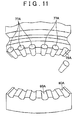
- truncated cone-shaped pins 77A and retention grooves 79A and tooth grooves 80A that coincide with the shapes of the pins 77A may be used.
- Each pin 77A has a diameter that reduces as it goes radially inward of the input member body 201.
- the first contact angle ⁇ is larger than the second contact angle ⁇ .
- the above embodiments are applied to a column electric power steering system in which the steering assist motor 25 is arranged in the steering column; however, the aspect of the invention is not limited to this configuration.
- the aspect of the invention may be applied to a rack assist electric power steering system in which the steering assist motor 25 is provided for a steering rack housing.
- the aspect of the invention may be applied to a pinion assist power steering system in which the steering assist motor 25 is arranged in the pinion shaft 15.
- the transmission ratio variable mechanism 5 is arranged in the steering shaft 3.
- the transmission ratio variable mechanism 5 may be arranged in the intermediate shaft 8 or the pinion shaft 15.
- the transmission ratio variable mechanism according to the aspect of the invention may be applied to another system other than a vehicle steering system.
- the transmission ratio variable mechanism according to the aspect of the invention may be, for example, used for a toe angle variable mechanism that is able to change the toe angle of a wheel of a vehicle, a camber angle variable mechanism that is able to change the camber angle of a wheel of a vehicle, or a damping force variable mechanism that is able to change the damping force of a shock absorber of a vehicle.
- the aspect of the invention may be applied to another gear set that includes first and second gears serving as a pair of gears or may be applied to a gear set provided for another general system other than a vehicle steering system.
- a first gear set includes an input member that serves as a first gear and an inner ring that serves as a second gear.
- a first end of the inner ring is inclined with respect to the input member and is in mesh with the input member.
- the input member has a plurality of retention grooves that are formed in an input member body and a plurality of pins that are retained in the respective retention grooves and that respectively constitute teeth of the input member.
- the first end has a plurality of tooth grooves that are engageable with the pins. A resultant force of forces applied to each pin from the retention groove and the tooth groove urges the pin toward the retention groove.
Landscapes
- Engineering & Computer Science (AREA)
- General Engineering & Computer Science (AREA)
- Mechanical Engineering (AREA)
- Chemical & Material Sciences (AREA)
- Combustion & Propulsion (AREA)
- Transportation (AREA)
- Retarders (AREA)
- Power Steering Mechanism (AREA)
- Gears, Cams (AREA)
Abstract
Description
- The disclosures of Japanese Patent Application No.
2009-004859 filed on January 13, 2009 - The invention relates to a gear set and a nutation gear set.
- Some of gear sets include two bevel gears in mesh with each other (for example, see Japanese Patent Application Publication No.
11-315908 JP-A-11-315908 - A situation that the rollers that constitute the convex teeth lift from the grooves of the first gear or slip off from the grooves (tooth jumping) leads to a torque loss or occurrence of noise, so it is undesirable.
JP-A-11-315908 - The invention provides a gear set and nutation gear set that are able to prevent lifting or slipping of members that constitute teeth.
- An aspect of the invention provides a gear set that includes: a first gear that is rotatable around a first axis; and a second gear that is rotatable around a second axis inclined with respect to the first axis, and that is in mesh with the first gear so that torque is transmittable. One of the first and second gears includes a plurality of retention grooves that are arranged so as to radiate around an axis of the one of the first and second gears and a plurality of pins that are retained in the respective retention grooves and that respectively constitute teeth of the one of the first and second gears. The other one of the first and second gears includes a plurality of tooth grooves that are arranged so as to radiate around an axis of the other one of the first and second gears and that are engageable with the pins. A resultant force of forces applied to each pin from the retention groove and the tooth groove urges the pin toward the retention groove.
- The foregoing and further objects, features and advantages of the invention will become apparent from the following description of example embodiments with reference to the accompanying drawings, wherein like numerals are used to represent like elements and wherein:
-
FIG 1 is a view that shows the schematic configuration of a vehicle steering system equipped with a transmission ratio variable mechanism according to a first embodiment of the invention; -
FIG 2 is a cross-sectional view that shows the further specific configuration of a relevant portion ofFIG 1 ; -
FIG. 3 is an enlarged view of the transmission ratio variable mechanism ofFIG 2 and its surroundings; -
FIG. 4 is an enlarged view of a relevant portion of the transmission ratio variable mechanism ofFIG 3 ; -
FIG. 5 is a perspective view of a relevant portion of first concave convex engaging portions; -
FIG 6 is a perspective cross-sectional view that shows part of an input member; -
FIG 7 is an enlarged cross-sectional view of a relevant portion ofFIG. 6 ; -
FIG. 8 is a cross-sectional view of a relevant portion, taken along the line VIII-VIII inFIG 4 ; -
FIG. 9 is a cross-sectional view taken along the same line asFIG. 8 , illustrating the moment applied to a pin; -
FIG 10 is a graph that shows the relationship between a first contact angle and a second contact angle; and -
FIG. 11 is a perspective view of a relevant portion according to a second embodiment of the invention. - Embodiments of the invention will be described with reference to the accompanying drawings.
-
FIG. 1 is a view that shows the schematic configuration, of avehicle steering system 1 equipped with a transmission ratio variable mechanism according to a first embodiment of the invention. Referring toFIG. 1 , thevehicle steering system 1 applies steering torque, given to asteering member 2 such as a steering wheel, to respective right and left steeredwheels steering shaft 3, or the like. Thevehicle steering system 1 has a variable gear ratio (VGR) function. The VGR function is able to change a transmission ratio θ2/θ1 that is the ratio of a steered angle θ2 of each steered wheel to asteering angle θ1 1 of thesteering member 2. - The
vehicle steering system 1 includes thesteering member 2 and thesteering shaft 3 coupled to thesteering member 2. Thesteering shaft 3 includes first tothird shafts 11 to 13 that are arranged along the same axis. The respective central axes of the first tothird shafts 11 to 13 are also the rotation axes of the first tothird shafts 11 to 13. - The
steering member 2 is coupled to one end of thefirst shaft 11 so as to be integrally rotatable. The other end of thefirst shaft 11 is coupled to one end of thesecond shaft 12 via the transmissionratio variable mechanism 5 so as to be differentially rotatable. Thesecond shaft 12 and thethird shaft 13 are coupled with each other via atorsion bar 14 so that thesecond shaft 12 and thethird shaft 13 are elastically rotatable relative to each other within a predetermined range and torque transmission is allowed therebetween. - The
third shaft 13 is coupled to the steeredwheels universal joint 7, anintermediate shaft 8, a universal joint 9, a steeredmechanism 10, and the like. - The steered
mechanism 10 includes apinion shaft 15 and arack shaft 16. Thepinion shaft 15 is coupled to the universal joint 9. Therack shaft 16 has arack 16a that is in mesh with apinion 15a formed at the distal end of thepinion shaft 15. Therack shaft 16 serves as a steered shaft extending in a transverse direction of a vehicle.Knuckle arms rack shaft 16 viatie rods - With the above configuration, rotation of the
steering member 2 is transmitted to the steeredmechanism 10 via thesteering shaft 3, and the like. In the steeredmechanism 10, rotation of thepinion 15a is converted into axial movement of therack shaft 16. The axial movement of therack shaft 16 is transmitted via thetie rods corresponding knuckle arms knuckle arms wheels respective knuckle arms - The transmission
ratio variable mechanism 5 is used to change the rotational transmission ratio (transmission ratio θ2/θ1) between the first andsecond shafts steering shaft 3, and is formed as a nutation gear mechanism. The transmissionratio variable mechanism 5 includes aninput member 20, anoutput member 22 and araceway ring unit 39. Theinput member 20 is provided at the other end of thefirst shaft 11. Theoutput member 22 is provided at one end of thesecond shaft 12. Theraceway ring unit 39 serves as an intermediate member interposed between theinput member 20 and theoutput member 22. - The
input member 20 is coupled to thesteering member 2 and thefirst shaft 11 so that torque is transmittable. Theoutput member 22 is coupled to thesecond shaft 12 so that torque is transmittable. A first axis Z1 is the central axis and rotation axis of each of theinput member 20 and theoutput member 22. - The
output member 22 is coupled to the steeredwheels second shaft 12, the steeredmechanism 10, and the like. - The
raceway ring unit 39 includes aninner ring 391, anouter ring 392 and rollingelements 393 Theinner ring 391 serves as a first raceway ring. Theouter ring 392 serves as a second raceway ring. The rollingelements 393 are balls, or the like, interposed between theinner ring 391 and theouter ring 392, and constitute ball bearings. - The rolling
elements 393 may be cylindrical rollers, needle rollers and tapered rollers, other than balls. In addition, the rollingelements 393 may be arranged in a single row or in a double row. When the rollingelements 393 are arranged in a double row, it is desirable to prevent inclination of theinner ring 391 with respect to theouter ring 392. A double row angular bearing may be exemplified as a double row bearing. - The
inner ring 391 couples theinput member 20 to theoutput member 22 so as to be differentially rotatable. Theinner ring 391 and theouter ring 392 each have a second axis Z2 as a central axis that is inclined with respect to the first axis Z1. The second axis Z2 is inclined at a predetermined inclination angle with respect to the first axis Z1. Theinner ring 391 is rotatably supported by theouter ring 392 via the rollingelements 393, so theinner ring 391 is rotatable around the second axis Z2. Theinner ring 391 is also rotatable around the first axis Z1 as a transmission ratiovariable mechanism motor 23 is driven. The transmission ratiovariable mechanism motor 23 is an electric motor that serves as an actuator for driving theouter ring 392. Theinner ring 391 and theouter ring 392 are able to perform Coriolis motion (oscillating motion) around the first axis Z1. - The transmission ratio
variable mechanism motor 23 is arranged radially outward of theraceway ring unit 39, and has the first axis Z1 as a central axis. The transmission ratiovariable mechanism motor 23 changes the transmission ratio θ2/θ1 by varying the rotational speed of theouter ring 392 around the first axis Z1. - The transmission ratio
variable mechanism motor 23 is, for example, formed of a brushless motor. The transmission ratiovariable mechanism motor 23 includes arotor 231 and astator 232. Therotor 231 retains theouter ring 392 of theraceway ring unit 39. Thestator 232 surrounds therotor 231 and is fixed to ahousing 24 that serves as a steering column. Therotor 231 rotates around the first axis Z1. - The
vehicle steering system 1 includes a steering assistforce application mechanism 19 for applying steering assist force to thesteering shaft 3. The steering assistforce application mechanism 19 includes thesecond shaft 12, thethird shaft 13, atorque sensor 44, asteering assist motor 25 and adecelerating mechanism 26. Thesecond shaft 12 serves as an input shaft coupled to theoutput member 22 of the transmissionratio variable mechanism 5. Thethird shaft 13 serves as an output shaft coupled to the steeredmechanism 10. Thetorque sensor 44 detects torque transmitted between thesecond shaft 12 and thethird shaft 13 and will be described later. Thesteering assist motor 25 serves as a steering assist actuator. Thedecelerating mechanism 26 is interposed between the steering assistmotor 25 and thethird shaft 13. - The
steering assist motor 25 is formed of an electric motor, such as a brushless motor. The output of the steering assistmotor 25 is transmitted to thethird shaft 13 via thedecelerating mechanism 26. - The
decelerating mechanism 26 is, for example, formed of a worm mechanism. Thedecelerating mechanism 26 includes aworm shaft 27 and aworm gear 28. Theworm shaft 27 serves as a drive gear that is coupled to theoutput shaft 25a of the steering assistmotor 25. Theworm gear 28 serves as a driven gear that is in mesh with theworm shaft 27 and that is integrally rotatably coupled to thethird shaft 13. Note that thedecelerating mechanism 26 is not limited to the worm gear mechanism; thedecelerating mechanism 26 may be another gear mechanism, such as a parallel shaft gear mechanism using a spur gear or a helical gear. - The transmission
ratio variable mechanism 5 and the steering assistforce application mechanism 19 are provided for thehousing 24. Thehousing 24 is arranged inside a cabin of the vehicle. Note that thehousing 24 may be arranged so as to surround theintermediate shaft 8 or may be arranged inside an engine room of the vehicle. - The transmission ratio
variable mechanism motor 23 and the steering assistmotor 25 each are controlled to be driven by acontrol unit 29 that includes a CPU, a RAM and a ROM. Thecontrol unit 29 is connected to the transmission ratiovariable mechanism motor 23 via adrive circuit 40, and is connected to the steering assistmotor 25 via adrive circuit 41. - A
steering angle sensor 42, amotor resolver 43, thetorque sensor 44, a steered angle sensor 45, avehicle speed sensor 46 and ayaw rate sensor 47 are connected to thecontrol unit 29. Themotor resolver 43 serves as a rotation angle detector means for detecting the rotation angle of the transmission ratiovariable mechanism motor 23. Thetorque sensor 44 serves as a torque detector. - A signal indicating the rotation angle of the
first shaft 11 is input from thesteering angle sensor 42 to thecontrol unit 29 as a value corresponding to a steering angle θ1 that is an operation amount from the straight-ahead position of the steeringmember 2. A signal indicating the rotation angle θr of therotor 231 of the transmission ratiovariable mechanism motor 23 is input from themotor resolver 43 to thecontrol unit 29. A signal indicating torque applied between thesecond shaft 12 and thethird shaft 13 is input from thetorque sensor 44 to thecontrol unit 29 as a value corresponding to a steering torque T applied to the steeringmember 2. A signal indicating the rotation angle of thethird shaft 13 is input from the steered angle sensor 45 to thecontrol unit 29 as a value corresponding to a steered angle θ2. A signal indicating the vehicle speed V is input from thevehicle speed sensor 46 to thecontrol unit 29. A signal indicating the yaw rate γ of the vehicle is input from theyaw rate sensor 47 to thecontrol unit 29. - The
control unit 29 controls the transmission ratiovariable mechanism motor 23 and the steering assistmotor 25 for driving on the basis of signals from thesensors 42 to 47, or the like. - With the above configuration, the output of the transmission
ratio variable mechanism 5 is transmitted to the steeredmechanism 10 via the steering assistforce application mechanism 19. More specifically, the steering torque input to the steeringmember 2 is input to theinput member 20 of the transmissionratio variable mechanism 5 via thefirst shaft 11, and is transmitted from theoutput member 22 to thesecond shaft 12 of the steering assistforce application mechanism 19. The steering torque transmitted to thesecond shaft 12 is transmitted to thetorsion bar 14 and thethird shaft 13, and is transmitted to the steeredmechanism 10 together with the output from the steering assistmotor 25 via theintermediate shaft 8, or the like. -
FIG. 2 is a cross-sectional view that shows the specific configuration of a relevant portion ofFIG. 1 . Referring toFIG. 2 , thehousing 24 is, for example, made by forming metal, such as aluminum alloy, into a cylindrical shape. Thehousing 24 includes first tothird housings 51 to 53. First toseventh bearings 31 to 37 are accommodated in thehousing 24. The first tofifth bearings 31 to 35 and theseventh bearing 37 each are a rolling bearing, such as an angular ball bearing. Thesixth bearing 36 is a rolling bearing, such as a needle roller bearing. - The
first housing 51 has a cylindrical shape. Thefirst housing 51 constitutes a differential mechanism housing that accommodates the transmissionratio variable mechanism 5 serving as a differential mechanism. Thefirst housing 51 also constitutes a motor housing that accommodates the transmission ratiovariable mechanism motor 23. One end of thefirst housing 51 is covered with anend wall member 54. One end of thefirst housing 51 and theend wall member 54 are fixed to each other using afastening member 55, such as a bolt. Anannular protrusion 57 of one end of thesecond housing 52 is fitted to an innerperipheral surface 56 of the other end of thefirst housing 51. These first andsecond housings - The
second housing 52 has a cylindrical shape. Thesecond housing 52 constitutes a sensor housing and a resolver housing. The sensor housing accommodates thetorque sensor 44. The resolver housing accommodates themotor resolver 43. An innerperipheral surface 60 of one end of thethird housing 53 is fitted to an outerperipheral surface 59 of the other end of thesecond housing 52. - The
third housing 53 has a cylindrical shape. Thethird housing 53 constitutes a decelerating mechanism housing that accommodates thedecelerating mechanism 26. Anend wall portion 61 is provided at the other end of thethird housing 53. Theend wall portion 61 has an annular shape, and covers the other end of thethird housing 53. -
FIG. 3 is an enlarged view of the transmissionratio variable mechanism 5 ofFIG. 2 and its surroundings. Referring toFIG 3 , theinput member 20 andoutput member 22 of the transmissionratio variable mechanism 5 and theinner ring 391 of theraceway ring unit 39 each have an annular shape. - The
input member 20 is formed as a first gear. Theinput member 20 includes aninput member body 201, acylindrical body 202, a plurality ofpins 77, aninner retainer 75 and anouter retainer 76. Thecylindrical member 202 is arranged radially inward of theinput member body 201 and is integrally rotatable with theinput member body 201. The plurality ofpins 77 are retained by theinput member body 201. Theinner retainer 75 and theouter retainer 76 retain the plurality ofpins 77 by theinput member body 201. Theinput member body 201 and thecylindrical member 202 are integrally formed using a single material. - The other end of the
first shaft 11 is inserted through aninsertion hole 202a of thecylindrical member 202. The other end of thefirst shaft 11 that serves as the input shaft of the transmissionratio variable mechanism 5 is coupled to thecylindrical member 202 by, for example, serration engagement so that torque is transmittable. - The
output member 22 is formed as a first gear. Theoutput member 22 includes anoutput member body 221, acylindrical member 222, a plurality ofpins 87, aninner retainer 85 and anouter retainer 86. Thecylindrical member 222 is arranged radially inward of theoutput member body 221 and is integrally rotatable with theoutput member body 221. The plurality ofpins 87 are retained by theoutput member body 221. Theinner retainer 85 and theouter retainer 86 retain the plurality ofpins 87 by theoutput member body 221. Theoutput member body 221 and thecylindrical member 222 are integrally formed using a single material. - One end of the
second shaft 12 is inserted through aninsertion hole 222a of thecylindrical member 222 of theoutput member 22. An intermediate portion of thesecond shaft 12 that serves as the output shaft of the transmissionratio variable mechanism 5 is coupled to theoutput member 22 by, for example, serration engagement so that torque is transmittable. - The
inner ring 391 of theraceway ring unit 39 is all integrally formed using a single member, and is arranged between theinput member 20 and theoutput member 22. Theinner ring 391 is formed as a second gear that is paired with theinput member 20 serving as the first gear, and is formed as a second gear that is paired with theoutput member 22 serving as the first gear. With respect to the axial direction of theinner ring 391, afirst end 391a of theinner ring 391 is formed as a gear element of the second gear, and asecond end 391b of theinner ring 391 is formed as a gear element of the second gear. The first andsecond ends - The
input member 20 and theinner ring 391 that is in mesh with theinput member 20 so that torque is transmittable form a first gear set 78. The first gear set 78 is a bevel gear set. In addition, theoutput member 22 and theinner ring 391 that is in mesh with theoutput member 22 so that torque is transmittable form a second gear set 88. The second gear set 88 is a bevel gear set. In addition, the first gear set 78 and the second gear set 88 form a nutation gear set 84. Theinput member 20 andoutput member 22 of the nutation gear set have the common first axis Z1, and are arranged on opposite sides of thefirst end 391a andsecond end 391b of theinner ring 391. Theouter ring 392 is fixedly press-fitted into aninclined hole 63 that is formed on the inner periphery of therotor 23 of the transmission ratiovariable mechanism motor 23. Theouter ring 392 integrally rotates with therotor 231 around the first axis Z1. As therotor 231 rotates around the first axis Z1, theraceway ring unit 39 performs Coriolis motion. Note that theouter ring 392 may couple theinput member 20 to theoutput member 22 so as to be differentially rotatable, and theinner ring 391 may be integrally rotatably coupled to therotor 231 of the transmission ratiovariable mechanism motor 23. In this case, theraceway ring unit 39 is of an inner ring support type. -
FIG. 4 is an enlarged view of a relevant portion of the transmissionratio variable mechanism 5 ofFIG 3 . Referring toFIG. 4 , within thefirst end 391a of theinner ring 391, an end surface facing theinput member 20 is defined as afirst end surface 71. Within thesecond end 391b of theinner ring 391, an end surface facing theoutput member 22 is defined as asecond end surface 72. Theinput member 20 and thefirst end 391a of theinner ring 391 have first concave convexengaging portions 64. This allows torque transmission between theinput member 20 and thefirst end 391a. In addition, thesecond end 391b of theinner ring 391 and theoutput member 22 have second concave convexengaging portions 67. This allows torque transmission between thesecond end 391b and theoutput member 22. -
FIG. 5 is a perspective view of a relevant portion of the first concave convexengaging portions 64. Referring toFIG 4 andFIG 5 , atorque transmitting surface 70 that serves as one end surface of theinput member body 201 and thefirst end surface 71 of thefirst end 391a face each other in an axial direction S of the steering shaft 3 (hereinafter, simply referred to as axial direction S). The first concave convexengaging portions 64 engage thetorque transmitting surface 70 with thefirst end surface 71 so that torque is transmittable. The first concave convexengaging portions 64 include a plurality ofretention grooves 79, the plurality ofpins 77 and a plurality oftooth grooves 80. The plurality ofretention grooves 79 are formed on thetorque transmitting surface 70. The plurality ofpins 77 are retained in therespective retention grooves 79. The plurality oftooth grooves 80 are formed on thefirst end surface 71 of thefirst end 391a of theinner ring 391 and engage with thepins 77. Theinput member 20 constitutes one of the first and second gears, and has theretention grooves 79 and thepins 77. Theinner ring 391 constitutes the other one of the first and second gears, and has thetooth grooves 80. - Note that, in the present embodiment, the
input member 20 has theretention grooves 79 and thepins 77, and thefirst end 391a of theinner ring 391 has thetooth grooves 80; however, the configuration is not limited to this embodiment. Instead, it is also applicable that thefirst end 391a of theinner ring 391 has theretention grooves 79 and thepins 77 and theinput member body 201 has thetooth grooves 80. In this case, theinput member 20 is the other one of the first and second gears, and theinner ring 391 is one of the first and second gears. - The
retention grooves 79, thepins 77 and thetooth grooves 80 are arranged at equiangular intervals over the respective entire regions of the correspondingtorque transmitting surface 70 andfirst end surface 71 in the circumferential direction. - The
pins 77 are used for formingteeth 81 of theinput member 20, and are needle rollers each having, for example, a cylindrical shape. Thesepins 77 are arranged so as to radiate around the first axis Z1. Half of eachpin 77 protrudes from a corresponding one of theretention grooves 79 to have a semi-spherical shape in cross section. The protruded half serves as thetooth 81 of theinput member 20. Outer ends 77a of thepins 77 in the radial direction R1 of theinput member 20 are collectively retained by the annularouter retainer 76. Inner ends 77b of thepins 77 in the radial direction R1 of theinput member 20 are collectively retained by the annularinner retainer 75. - The
pins 77 are mounted on theinput member body 201 by theseouter retainer 76 andinner retainer 75. Theouter retainer 76 and theinner retainer 75 each are made of an elastic member, such as synthetic resin. -
FIG. 6 is a perspective cross-sectional view that shows part of theinput member 20.FIG. 7 is an enlarged cross-sectional view of a relevant portion ofFIG 6 . Referring toFIG 6 and FIG 7 , theouter retainer 76 has anannular body 91. Oneend 91a of thebody 91 in the axial direction has anannular protrusion 92 that protrudes radially inward of thebody 91. Theother end 91b of thebody 91 in the axial direction has an annular engagingprotrusion 93 that protrudes radially inward of thebody 91. - The outer ends 77a of the
pins 77 are held and retained by theannular protrusion 92 and theretention grooves 79 of theinput member body 201. The engagingprotrusion 93 is engaged with an engagingportion 94 that is an annular recess formed on an outer periphery of theinput member body 201. By so doing, theouter retainer 76 is mounted on theinput member body 201. - The
inner retainer 75 has anannular body 95. Oneend 95a of thebody 95 in the axial direction has anannular protrusion 96 that protrudes radially outward of thebody 95. Theother end 95b of thebody 95 in the axial direction has an annular engagingprotrusion 97 that protrudes radially outward of thebody 95. The inner ends 77b of thepins 77 are held and retained by theannular protrusion 96 and theretention grooves 79 of theinput member body 201. The engagingprotrusion 97 is engaged with an engagingportion 98 that is an annular recess formed on an inner periphery of theinput member body 201. By so doing, theinner retainer 75 is mounted on theinput member body 201. - Referring to
FIG. 5 , theretention grooves 79 are formed in a long slender shape so as to radiate around the first axis Z1. Theretention grooves 79 extend over the entire region of thetorque transmitting surface 70 in the radial direction of theinput member 20, and are arranged at equiangular intervals in the circumferential direction of theinput member body 201. The number of theretention grooves 79 is equal to the number of thepins 77. Thepins 77 are retained in theretention grooves 79. Note thatFIG. 5 does not show theinner retainer 75 or theouter retainer 76. - The
tooth grooves 80 are formed in a long slender shape so as to radiate around the second axis Z2. Thetooth grooves 80 extend over the entire region of thefirst end 391a in the radial direction of theinner ring 391, and are arranged at equiangular intervals in the circumferential direction of thefirst end 391a. The number of thetooth grooves 80 is equal to the number of thepins 77 or is different from the number of thepins 77. Depending on a difference between the number of thepins 77 and the number of thetooth grooves 80, it is possible to change the speed between theinput member body 201 and theinner ring 391. - Referring back to
FIG 4 , the second axis Z2 of theinner ring 391 is inclined by a predetermined angle σ with respect to the first axis Z1 of theinput member 20. Thus, part of theteeth 81 and part of thetooth grooves 80 are in mesh with each other. -
FIG. 8 is a cross-sectional view of a relevant portion, taken along the line VIII-VIII inFIG. 4 .FIG. 8 shows a cross section perpendicular to the longitudinal direction of the pin 77 (pin 771) that is in mesh with thetooth groove 80. When described with reference toFIG. 8 , the cross section perpendicular to thepin 771 is used as a reference. - Referring to
FIG 8 , one of the features of the present embodiment is that a resultant force F1 + F2 of a force F1 applied to thepin 77 from theretention groove 79 and a force F2 applied to thepin 77 from thetooth groove 80 urges thepin 77 toward a bottom 79a of theretention groove 79 between the bottom 79a of theretention groove 79 and a bottom 80a of thetooth groove 80. - Specifically, the cross section of an
inner surface 79b of theretention groove 79 of theinput member body 201 has a so-called Gothic arch shape, so the bottom 79a has a sharp shape. The shape of the cross section of theinner surface 79b is the same over the entire region of theretention groove 79 in the longitudinal direction. Theinner surface 79b has a pair offirst portions retention groove 79 and that are arranged in the circumferential direction G of theinput member 20. Thefirst portion 79c is a circular arc surface having a relatively smaller predetermined curvature radius U1. Thefirst portion 79d and thefirst portion 79c have symmetrical shapes. Thefirst portion 79d is a circular arc surface having the same curvature radius U1 as that of thefirst portion 79c. The center ofcurvature 79e of thefirst portion 79c and the center of curvature 79f of thefirst portion 79d are offset from each other in the circumferential direction G - In addition, the cross section of an inner surface 80b of the
tooth groove 80 formed on thefirst end 391a of theinner ring 391 has a so-called Gothic arch shape, so the bottom 80a has a sharp shape. The shape of the cross section of the inner surface 80b is the same over the entire region of thetooth groove 80 in the longitudinal direction. The inner surface 80b has a pair ofsecond portions tooth groove 80 and that are arranged in the circumferential direction of theinner ring 391. Thesecond portion 80c is a circular arc surface having a relatively large predetermined curvature radius U2. Thesecond portion 80d and thesecond portion 80c have symmetrical shapes. Thesecond portion 80d is a circular arc surface having the same curvature radius U2 as that of thesecond portion 80c. The center ofcurvature 80e of thesecond portion 80c and the center ofcurvature 80f of thesecond portion 80d are offset from each other in the circumferential direction of theinner ring 391. - The outer
peripheral surface 77c of thepin 77 and the pair offirst portions retention groove 79 are in contact with each other at correspondingfirst contact points peripheral surface 77c of thepin 77 and the pair ofsecond portions tooth groove 80 are in contact with each other at corresponding second contact points 100c and 100d (contact lines). That is, thepin 77 is in contact with theretention groove 79 and thetooth groove 80 at four contact points. - The
first portion 79c of theretention groove 79 and thesecond portion 80c of thetooth groove 80 face each other via the central axis J1 of thepin 77. Thefirst portion 79c of theretention groove 79 makes a first contact angle β with thepin 77 at thefirst contact point 99c. The first contact angle β is an angle made between areference plane 101 and the line of action of the first force F1. Thereference plane 101 includes the central axis J1 of thepin 77 and the first axis Z1. The first force F1 serves as a force applied from thefirst portion 79c of theretention groove 79 to thefirst contact point 99c of thepin 77. In addition, thesecond portion 80c of thetooth groove 80 makes a second contact angle α with thepin 77 at thesecond contact point 100c. The second contact angle α is an angle made between thereference plane 101 and the line of action of the second force F2. The second force F2 serves as a force applied from thesecond portion 80c of thetooth groove 80 to thesecond contact point 100c of thepin 77. As described above, the curvature radius U1 of thefirst portion 79c of theretention groove 79 is relatively small, and the curvature radius U2 of thesecond portion 80c of thetooth groove 80 is relatively large, so the second contact angle α is relatively small and the first contact angle β is relatively large (α < β). - With the above configuration, when the
input member 20 rotates in one direction G1 in the circumferential direction G, a component F1y of the first force F1 in a direction Y parallel to thereference plane 101 and in a direction Y1 from theretention groove 79 toward thetooth groove 80 is relatively small. In addition, a component F2y of the second force F2 in the direction Y parallel to thereference plane 101 and in a direction Y2 from thetooth groove 80 toward theretention groove 79 is relatively large. Thus, the sum F1y + F2y of the component F1y of the first force F1 and the component F2y of the second force F2, parallel to thereference plane 101, is directed in the direction Y2 from thetooth groove 80 toward theretention groove 79 in the direction Y parallel to thereference plane 101, and acts to urge thepin 77 toward the bottom 79 of theretention groove 79. - In addition, the
first portion 79d of theretention groove 79 and thefirst portion 79c have symmetrical shapes, and thesecond portion 80d of thetooth groove 80 and thesecond portion 80c have symmetrical shapes. By so doing, when theinput member 20 rotates in the other direction G2 in the circumferential direction G as well, as in the case where theinput member 20 rotates in the one direction G1, force that urges theretention groove 79 toward the bottom 79a of theretention groove 79 is applied to thepin 77. -
FIG 9 is a cross-sectional view taken along the same line asFIG 8 , illustrating the moment applied to thepin 77. Referring toFIG. 9 , another feature of the present embodiment is that, in order to further reliably prevent thepin 77 from slipping off from theretention groove 79, between a first moment M1 and a second moment M2 around thefirst contact point 99c, the first moment M1 is larger than the second moment M2. - The first moment M1 is a moment that the second force F2 applied to the
pin 77 from thesecond portion 80c of the inner surface 80b of thetooth groove 80 rotates thepin 77 in one direction H1 around thefirst contact point 99c. The second moment M2 is a moment that a frictional force F3 of thepin 77 against thefirst portion 80c of the inner surface 80b of thetooth groove 80 rotates thepin 77 in the other direction H2 around thefirst contact point 99c. - By increasing the second moment M2 as compared with the first moment M1, the sum M1 + M2 of these moments M1 and M2 is applied in the one direction H1 around the
first contact point 99c. Thus, thepin 77 is urged toward the bottom 79a of theretention groove 79, and it is possible to further reliably prevent thepin 77 from slipping off from theretention groove 79. - In order to increase the first moment M1 as compared with the second moment M2, the coefficient of friction between the
pin 77 and thesecond portion 80c of thetooth groove 80 is defined as µ, the following inequality (1) holds.
- First, in
FIG 9 , where the line segment that connects thefirst contact point 99c to thesecond contact point 100c is a line segment AB, the line segment that connects thefirst contact point 99c to the central axis J1 of thepin 77 is a line segment AO and the line segment that connects thesecond contact point 100c to the central axis J1 of thepin 77 is a line segment BO, a triangle OAB is an isosceles triangle such that the length of the line segment AO and the length of the line segment BO each are equal to the radius of thepin 77. Thus, an angle OAB and an angle OBA each are a predetermined angle θ. In addition, where the tangent of the outerperipheral surface 77c of thepin 77 at point B (second contact point 100c) is a tangent B1 and the straight line that passes through the point B and that intersects at a right angle with the line segment AB is a straight line B2, an inclination angle made between the tangent B1 and the straight line B2 is the predetermined angle θ. In addition, an angle made between the line segment BO and a portion of the straight line B2 extending from the point B toward theretention groove 79 is (90-θ)°. - Here, when the
input member 20 rotates in the one direction G1 in the circumferential direction, the above described second force F2 is applied from thetooth groove 80 to thesecond contact point 100c, and the frictional force F3 caused by frictional contact between thepin 77 and thetooth groove 80 is also applied to thesecond contact point 100c. - The frictional force F3 is obtained by the equation F3 = µ×F2. From
FIG. 9 , a component F3' of the frictional force F3 in the straight line B2 direction is obtained by the equation F3' = F3×cosθ = F2×µ×cosθ. Thus, where the length of the line segment AB is defined as L, the second moment M2 that the frictional force F3 rotates thepin 77 in the other direction H2 around thefirst contact point 99c is expressed by the following mathematical expression (2).
- In addition, from
FIG. 9 , a component of the second force F2 in the straight line B2 direction is expressed by F2' = F2×cos(90-θ) = F2×sinθ. Thus, the first moment M1 that the second force F2 rotates thepin 77 in one direction H1 around thefirst contact point 99c is expressed by the following mathematical expression (3).
- Accordingly, when the first moment M1 is larger than the second moment M2, that is, when the mathematical expression (2) < the mathematical expression (3), a moment M1 + M2 that rotates the
pin 77 in one direction H2 around thefirst contact point 99c is applied to thepin 77, and thepin 77 is urged toward the bottom 79a of theretention groove 79 by the moment M1 + M2. - The relationship the mathematical expression (2) < the mathematical expression (3) is equivalent to F2×µ×cosθ×L < F2×sinθ×L. When the above inequality is divided by F2 and L, µcosθ < sinθ is obtained, and it may be transformed into µ < sinθ/cosθ. Therefore, the following inequality is obtained.

- Here, when the isosceles triangle OBA is used, because the sum of the interior angles of the triangle OBA is 180°, so it holds that 180 = θ + θ + {α + 90 + (90 - β)} = 2×θ + 180 + α - β. Thus, 2×θ = β-α, so θ = (β - α)/2.
- When the above θ is substituted into the inequality (4), µ < tan{(β - α)/2} is obtained. Thus, tan-1(µ) < (β - α)/2 is obtained. When the above inequality is transformed, (β - α) > 2×tan-1(µ), that is, the inequality (1), is obtained.
- Thus, to urge the
pin 77 toward the bottom 79a of theretention groove 79 by the moment around thefirst contact point 99c, it is only necessary that a difference in angle (β - α) between the first contact angle β and the second contact angle α is larger than 2×tan-1(µ). - For example, when the coefficient of friction µ is 0.1, it is only necessary that the difference in angle (β - α) is larger than 2×tan-1(0.1) ≈ 11.42°. Therefore, the first contact angle β and the second contact angle α may be, for example, set so as to satisfy the relationship shown in the graph of
FIG. 10 . The first contact angle β is larger the more desirable. However, because of restrictions on machining of theretention groove 79, the first contact angle β is, for example, set at about 81° ± 2°. In addition, the second contact angle α is, for example, set at about 66.5° ± 2° in terms of prevention of slipping of thepin 77. The above ±2° is a dimensional tolerance. - In addition, the
first portion 79d of theretention groove 79 and thefirst portion 79c have symmetrical shapes, and thesecond portion 80d of thetooth groove 80 and thesecond portion 80c have symmetrical shapes. By so doing, when theinput member 20 rotates in the other direction G2 in the circumferential direction G as well, as in the case where theinput member 20 rotates in the one direction G1, moment that urges thepin 77 toward the bottom 79a of theretention groove 79 is applied to thepin 77. - Referring to
FIG. 4 , thetorque transmitting surface 73 that serves as one end surface of theoutput member body 221 and thesecond end surface 72 of theinner ring 391 face each other in the axial direction S, and the second concave convexengaging portions 67 engage thetorque transmitting surface 73 with thesecond end surface 72 so that torque is transmittable. The second concave convexengaging portions 67 include a plurality of retention grooves 109, a plurality ofpins 87 and a plurality of tooth grooves 110. The plurality of retention grooves 109 are formed on thetorque transmitting surface 73. The plurality ofpins 87 are retained in the respective retention grooves 109. The plurality of tooth grooves 110 are formed on thesecond end surface 72 of thesecond end 391b of theinner ring 391 and engage with thepins 87. Theoutput member 22 constitutes one of the first and second gears, and has the retention grooves 109 and thepins 87. Theinner ring 391 constitutes the other one of the first and second gears, and has the tooth grooves 110. - Note that, in the present embodiment, the
output member 22 has the retention grooves 109 and thepins 87, and thesecond end 391b of theinner ring 391 has the tooth grooves 110; however, the configuration is not limited to this embodiment. Instead, it is also applicable that thesecond end 391b of theinner ring 391 has the retention grooves 109 and thepins 87 and theoutput member body 221 has the tooth grooves 110. In this case, theoutput member 22 is the other one of the first and second gears, and theinner ring 391 is one of the first and second gears. - The retention grooves 109 and pins 87 of the second concave convex
engaging portions 67 have similar configuration to theretention grooves 79 and pins 77 of the first concave convexengaging portions 64. The tooth grooves 110 of the second concave convexengaging portions 67 have similar configuration to thetooth grooves 80 of the first concave convexengaging portions 64. Therefore, the detailed description of the second concave convexengaging portions 67 is omitted. In addition, theinner retainer 85 and theouter retainer 86 for retaining thepins 87 of the second concave convexengaging portions 67 are provided. Theseretainers inner retainer 75 andouter retainer 76, so the detailed description thereof is omitted. - Referring to
FIG. 3 , therotor 231 of the transmission ratiovariable mechanism motor 23 includes acylindrical rotor core 112 and apermanent magnet 113. Therotor core 112 extends in the axial direction S. Thepermanent magnet 113 is fixed to an outer peripheral surface of therotor core 112. In the present embodiment, therotor core 112 that supports theouter ring 392 of theraceway ring unit 39 rotatably supports thecylindrical member 202 of theinput member 20 via afirst bearing 31, and rotatably supports thecylindrical member 222 of theoutput member 22 via athird bearing 33. In addition, therotor core 112 is supported at both ends by second andfourth bearings third bearings second bearing 32 is held in anannular protrusion 114 that is formed on an inner peripheral portion of one end of thefirst housing 51. Thefourth bearing 34 is held on an annular extendingportion 115 formed on an inner peripheral portion of the other end of thesecond housing 52. The annular extendingportion 115 has a cylindrical shape that extends from apartition wall portion 116 provided at the other end of thesecond housing 52 toward the one direction S1 in the axial direction S, and is inserted in therotor core 112. - The
stator 232 of the transmission ratiovariable mechanism motor 23 is fixed to the inner peripheral surface of thefirst housing 51 by shrinkage fitting, or the like, and surrounds thepermanent magnet 113 of therotor 231. - The
motor resolver 43 includes aresolver rotor 117 and aresolver stator 118. Theresolver rotor 117 is fixed to the outer peripheral surface of the other end of therotor core 112. Theresolver stator 118 is fixed to the inner peripheral surface of thesecond housing 52. - The
torque sensor 44 is arranged radially inward of therotor core 112 of the transmission ratiovariable mechanism motor 23. - Referring to
FIG. 2 , afifth bearing 35 is arranged on the other side S2 of thetorque sensor 44 in the axial direction S. Thefifth bearing 35 is held at thepartition wall portion 116 of thesecond housing 52, and rotatably supports one end of thethird shaft 13. Thesecond shaft 12 and thethird shaft 13 are rotatably supported relative to each other via asixth bearing 36. Aseventh bearing 37 is interposed between an intermediate portion of thethird shaft 13 and theend wall portion 61 of thethird housing 53. Theend wall portion 61 rotatably supports thethird shaft 13 via theseventh bearing 37. - As described above, according to the present embodiment, in the first gear set 78, the resultant force F1 + F2 of forces applied to each
pin 77 from theretention groove 79 and thetooth groove 80 is configured to urge thepin 77 toward the bottom 79a of theretention groove 79. By so doing, it is possible to urge thepin 77 so as not to slip off from theretention groove 79. Thus, it is possible to prevent lifting or slipping of thepins 77 that constitute theteeth 81. As a result, it is possible to suppress a torque loss or occurrence of noise in the first gear set 78. - In the second gear set 88 as well, because of a function similar to the function of the first gear set 78, it is possible to further reliably prevent lifting or slipping of the
pins 87 that constitute theteeth 111 from theoutput member body 221. As a result, it is possible to suppress a torque loss or occurrence of noise in the second gear set 88. - In addition, in the first gear set 78, the first contact angle β at which the
pin 77 contacts with theretention groove 79 is larger than the second contact angle α at which the pin contacts with thetooth groove 80. By so doing, the component F1y of the force F1 applied from theretention groove 79 to thepin 77 in the direction Y1 from theretention groove 79 toward thetooth groove 80 may be relatively reduced, and the component F2y of the force F2 applied from thetooth groove 80 to thepin 77 in the direction Y2 from thetooth groove 80 toward theretention groove 79 may be relatively increased. By so doing, the sum F1y + F2y of the two components F1y and F2y is directed in the direction Y2 from thetooth groove 80 toward theretention groove 79, so it is possible to reliably urge thepin 77 toward theretention groove 79 of theinput member body 201. - In the second gear set 88 as well, because of a function similar to the function of the first gear set 78, it is possible to reliably urge the
pin 87 toward the retention groove 109 of theoutput member body 221. - Furthermore, in the first gear set 78, the first moment M1 is larger than the second moment M2 associated with the
pin 77. The first moment M1 is a moment that urges thepin 77 toward the bottom 79a of theretention groove 79. The second moment M2 is a moment that acts to cause thepin 77 to slip off from theretention groove 79. The first moment M1 is larger than the second moment M2, so the sum M1 + M2 of the first and second moments M1 and M2 becomes a moment that urges thepin 77 toward the bottom 79a of theretention groove 79. Thus, it is possible to further reliably prevent thepin 77 from slipping off from theretention groove 79 of theinput member body 201. - In the second gear set 88 as well, because of a function similar to the function of the first gear set 78, it is possible to further reliably prevent the
pin 87 from slipping off from the retention groove 109 of theoutput member body 221. - In addition, in the first gear set 78, force applied to the
inner retainer 75 and theouter retainer 76 from thepins 77 may be small, so the strength necessary for theseinner retainer 75 andouter retainer 76 may be small. Thus, it is possible to reduce the size of the first gear set 78 by reducing the size of theinner retainer 75 and the size of theouter retainer 76. - In the second gear set 88 as well, because of similar advantageous effects to those of the first gear set 78, it is possible to reduce the size of the second gear set 88 by reducing the size of the
inner retainer 85 and the size of theouter retainer 86. - The aspect of the invention is not limited to the embodiment described above; it may be modified in various forms within the scope of the appended claims.
- For example, as in the case of a second embodiment shown in
FIG. 11 , truncated cone-shapedpins 77A andretention grooves 79A andtooth grooves 80A that coincide with the shapes of thepins 77A may be used. Eachpin 77A has a diameter that reduces as it goes radially inward of theinput member body 201. - In addition, it is also applicable that, in only one of the first and second gear sets 78 and 88, the first contact angle β is larger than the second contact angle α.
- Furthermore, the above embodiments are applied to a column electric power steering system in which the steering assist
motor 25 is arranged in the steering column; however, the aspect of the invention is not limited to this configuration. For example, the aspect of the invention may be applied to a rack assist electric power steering system in which the steering assistmotor 25 is provided for a steering rack housing. In addition, the aspect of the invention may be applied to a pinion assist power steering system in which the steering assistmotor 25 is arranged in thepinion shaft 15. - Furthermore, in the above embodiments, the transmission
ratio variable mechanism 5 is arranged in thesteering shaft 3. Instead, the transmissionratio variable mechanism 5 may be arranged in theintermediate shaft 8 or thepinion shaft 15. - In addition, the transmission ratio variable mechanism according to the aspect of the invention may be applied to another system other than a vehicle steering system. For example, the transmission ratio variable mechanism according to the aspect of the invention may be, for example, used for a toe angle variable mechanism that is able to change the toe angle of a wheel of a vehicle, a camber angle variable mechanism that is able to change the camber angle of a wheel of a vehicle, or a damping force variable mechanism that is able to change the damping force of a shock absorber of a vehicle.
- Furthermore, the aspect of the invention may be applied to another gear set that includes first and second gears serving as a pair of gears or may be applied to a gear set provided for another general system other than a vehicle steering system.
- A first gear set includes an input member that serves as a first gear and an inner ring that serves as a second gear. A first end of the inner ring is inclined with respect to the input member and is in mesh with the input member. The input member has a plurality of retention grooves that are formed in an input member body and a plurality of pins that are retained in the respective retention grooves and that respectively constitute teeth of the input member. The first end has a plurality of tooth grooves that are engageable with the pins. A resultant force of forces applied to each pin from the retention groove and the tooth groove urges the pin toward the retention groove.
Claims (9)
- A gear set comprising:a first gear that is rotatable around a first axis; anda second gear that is rotatable around a second axis inclined with respect to the first axis, and that is in mesh with the first gear so that torque is transmittable, whereinone of the first and second gears includes a plurality of retention grooves that are arranged so as to radiate around an axis of the one of the first and second gears and a plurality of pins that are retained in the respective retention grooves and that respectively constitute teeth of the one of the first and second gears, whereinthe other one of the first and second gears includes a plurality of tooth grooves that are arranged so as to radiate around an axis of the other one of the first and second gears and that are engageable with the pins, and whereina resultant force of forces applied to each pin from the retention groove and the tooth groove urges the pin toward the retention groove.
- The gear set according to claim 1, wherein a first contact angle at which each pin contacts with an inner surface of the retention groove is larger than a second contact angle at which the pin contacts with an inner surface of the tooth groove.
- The gear set according to claim 1 or 2, wherein a first moment that force applied to each pin from the tooth groove rotates the pin around a contact point between the retention groove and the pin is larger than a second moment that frictional force of the pin against the inner surface of the tooth groove rotates the pin around the contact point.
- A nutation gear set comprising:a pair of first gears that are arranged to face each other so as to be rotatable around a first axis; anda pair of second gears that are formed on both surfaces of an intermediate member interposed between the pair of first gears, that are rotatable around a second axis inclined with respect to the first axis, and that are respectively in mesh with the first gears so that torque is transmittable, whereinone of the pair of first gears and the pair of second gears include a plurality of retention grooves that are arranged so as to radiate around an axis of the one of the pair of first gears and the pair of second gears and a plurality of pins that are retained in the respective retention grooves and that constitute teeth of the one of the pair of first gears and the pair of second gears, whereinthe other one of the pair of first gears and the pair of second gears include a plurality of tooth grooves that are arranged so as to radiate around an axis of the other one of the pair of first gears and the pair of second gears and that are engageable with the pins, and whereina resultant force of forces applied to each pin from the retention groove and the tooth groove urges the pin toward the retention groove.
- The nutation gear set according to claim 4, wherein a first contact angle at which each pin contacts with an inner surface of the retention groove is larger than a second contact angle at which the pin contacts with an inner surface of the tooth groove.
- The nutation gear set according to claim 4 or 5, wherein a first moment that force applied to each pin from the tooth groove rotates the pin around a contact point between the retention groove and the pin is larger than a second moment that frictional force of the pin against the inner surface of the tooth groove rotates the pin around the contact point.
- A nutation gear set comprising:a pair of first gears that are arranged to face each other so as to be rotatable around a first axis; anda pair of second gears that are formed on both surfaces of an intermediate member interposed between the pair of first gears, that are rotatable around a second axis inclined with respect to the first axis, and that are respectively in mesh with the first gears so that torque is transmittable, whereinthe pair of first gears include a plurality of retention grooves that are arranged so as to radiate around the first axis and a plurality of pins that are retained in the respective retention grooves by a pair of retainers and that constitute teeth of the pair of first gears, whereinthe pair of second gears include a plurality of tooth grooves that are arranged so as to radiate around the second axis and that are engageable with the pins, and whereina resultant force of forces applied to each pin from the retention groove and the tooth groove urges the pin toward the retention groove.
- The nutation gear set according to claim 7, wherein a first contact angle at which each pin contacts with an inner surface of the retention groove is larger than a second contact angle at which the pin contacts with an inner surface of the tooth groove.
- The nutation gear set according to claim 7 or 8, wherein a first moment that force applied to each pin from the tooth groove rotates the pin around a contact point between the retention groove and the pin is larger than a second moment that frictional force of the pin against the inner surface of the tooth groove rotates the pin around the contact point.
Applications Claiming Priority (1)
| Application Number | Priority Date | Filing Date | Title |
|---|---|---|---|
| JP2009004859A JP5433238B2 (en) | 2009-01-13 | 2009-01-13 | Gear device and swing gear device |
Publications (2)
| Publication Number | Publication Date |
|---|---|
| EP2206936A1 true EP2206936A1 (en) | 2010-07-14 |
| EP2206936B1 EP2206936B1 (en) | 2011-09-28 |
Family
ID=41719310
Family Applications (1)
| Application Number | Title | Priority Date | Filing Date |
|---|---|---|---|
| EP10150538A Not-in-force EP2206936B1 (en) | 2009-01-13 | 2010-01-12 | Gear set and nutation gear set |
Country Status (5)
| Country | Link |
|---|---|
| US (1) | US8216104B2 (en) |
| EP (1) | EP2206936B1 (en) |
| JP (1) | JP5433238B2 (en) |
| CN (1) | CN101776130B (en) |
| AT (1) | ATE526524T1 (en) |
Cited By (1)
| Publication number | Priority date | Publication date | Assignee | Title |
|---|---|---|---|---|
| FR3163701A1 (en) | 2024-06-24 | 2025-12-26 | Compagnie Engrenages Et Reducteurs - Messian - Durand | Assembly for spring coupling, spring coupling and corresponding method |
Families Citing this family (11)
| Publication number | Priority date | Publication date | Assignee | Title |
|---|---|---|---|---|
| JP5282938B2 (en) * | 2008-07-07 | 2013-09-04 | 株式会社ジェイテクト | Transmission ratio variable mechanism and vehicle steering apparatus including the same |
| US20110017005A1 (en) * | 2009-07-22 | 2011-01-27 | International Truck Intellectual Property Company, Llc | Reduced friction ring and pinion gear set |
| JP5423461B2 (en) * | 2010-02-12 | 2014-02-19 | 株式会社ジェイテクト | Machining method of oscillating gear |
| JP2014035016A (en) * | 2012-08-08 | 2014-02-24 | Jtekt Corp | Transmission ratio variable device |
| JP2014098469A (en) * | 2012-11-16 | 2014-05-29 | Jtekt Corp | Transmission ratio variable device |
| JP6305076B2 (en) * | 2014-01-29 | 2018-04-04 | キヤノン株式会社 | Gear mechanism, transmission, and articulated robot arm |
| TWI720967B (en) * | 2015-03-02 | 2021-03-11 | 日商Thk股份有限公司 | Decelerating or accelerating device |
| JP6954817B2 (en) * | 2017-11-30 | 2021-10-27 | ナブテスコ株式会社 | Auxiliary device |
| US11105397B2 (en) | 2018-05-15 | 2021-08-31 | Robotis Co., Ltd. | Gear module comprising two-point contact internal gear |
| CN108533708B (en) * | 2018-06-15 | 2022-08-09 | 王踊 | Thrust hobbing gear and transmission device using same |
| CN111237400B (en) * | 2020-03-20 | 2023-01-17 | 苏州大学 | Double spherical cycloidal roller nutation drive |
Citations (4)
| Publication number | Priority date | Publication date | Assignee | Title |
|---|---|---|---|---|
| DE19757671A1 (en) * | 1996-12-28 | 1998-10-15 | Namu Co | Machining device with rotary table |
| US5945610A (en) | 1995-12-21 | 1999-08-31 | Galasso; Piero | Apparatus for detecting and displaying pressures of the foot-sole at a standstill and during movement |
| US5954610A (en) * | 1997-03-04 | 1999-09-21 | Namu Co., Ltd. | Speed change gear assembly |
| JP2008138765A (en) * | 2006-12-01 | 2008-06-19 | Ogino Kogyo Kk | Oscillating gear unit |
Family Cites Families (6)
| Publication number | Priority date | Publication date | Assignee | Title |
|---|---|---|---|---|
| IS988B6 (en) * | 1975-04-15 | 1978-03-08 | Balcke-Dürr AG. | Gear system |
| CN1018567B (en) * | 1988-06-30 | 1992-10-07 | 湖南省机械研究所 | Mixed few-differential spider reducer and speed variator |
| EP0412767A3 (en) * | 1989-08-08 | 1992-11-19 | Tai-Her Yang | A rigid harmonic speed reduction or angle cutting driving method and structure |
| JPH0544794A (en) * | 1991-08-08 | 1993-02-23 | Hitachi Ltd | Reduction gear with rocking rotary plate |
| JPH11315908A (en) * | 1998-05-06 | 1999-11-16 | Namu:Kk | Gear pair and Coriolis motion gear device |
| US6348021B1 (en) * | 1999-12-15 | 2002-02-19 | Alphonse J. Lemanski | Variable speed power transmission |
-
2009
- 2009-01-13 JP JP2009004859A patent/JP5433238B2/en active Active
- 2009-12-14 CN CN200910254282.7A patent/CN101776130B/en active Active
-
2010
- 2010-01-06 US US12/652,880 patent/US8216104B2/en not_active Expired - Fee Related
- 2010-01-12 EP EP10150538A patent/EP2206936B1/en not_active Not-in-force
- 2010-01-12 AT AT10150538T patent/ATE526524T1/en not_active IP Right Cessation
Patent Citations (4)
| Publication number | Priority date | Publication date | Assignee | Title |
|---|---|---|---|---|
| US5945610A (en) | 1995-12-21 | 1999-08-31 | Galasso; Piero | Apparatus for detecting and displaying pressures of the foot-sole at a standstill and during movement |
| DE19757671A1 (en) * | 1996-12-28 | 1998-10-15 | Namu Co | Machining device with rotary table |
| US5954610A (en) * | 1997-03-04 | 1999-09-21 | Namu Co., Ltd. | Speed change gear assembly |
| JP2008138765A (en) * | 2006-12-01 | 2008-06-19 | Ogino Kogyo Kk | Oscillating gear unit |
Cited By (1)
| Publication number | Priority date | Publication date | Assignee | Title |
|---|---|---|---|---|
| FR3163701A1 (en) | 2024-06-24 | 2025-12-26 | Compagnie Engrenages Et Reducteurs - Messian - Durand | Assembly for spring coupling, spring coupling and corresponding method |
Also Published As
| Publication number | Publication date |
|---|---|
| JP5433238B2 (en) | 2014-03-05 |
| ATE526524T1 (en) | 2011-10-15 |
| EP2206936B1 (en) | 2011-09-28 |
| CN101776130B (en) | 2014-09-03 |
| US8216104B2 (en) | 2012-07-10 |
| US20100179012A1 (en) | 2010-07-15 |
| CN101776130A (en) | 2010-07-14 |
| JP2010164088A (en) | 2010-07-29 |
Similar Documents
| Publication | Publication Date | Title |
|---|---|---|
| EP2206936B1 (en) | Gear set and nutation gear set | |
| EP2230154B1 (en) | Oscillating gear device, transmission ratio variable mechanism, and motor vehicle steering system | |
| EP2918862B1 (en) | Torque transmission joint and electric power steering device | |
| JP5234314B2 (en) | Vehicle steering system | |
| EP2615329B1 (en) | Speed reduction mechanism, and motor torque transmission device including the same | |
| US9033840B2 (en) | Speed reduction mechanism and motor torque transmission apparatus including the same | |
| EP2202131B1 (en) | Transmission ratio variable mechanism and steering device for vehicle equipped with it | |
| EP2298624B1 (en) | Transmission ratio variable mechanism and vehicle steering apparatus including the same | |
| EP2298623A1 (en) | Transmission ratio changing mechanism and vehicle steering device | |
| EP2090495A1 (en) | Vehicle steering device | |
| JP5234313B2 (en) | Vehicle steering system | |
| JP5257682B2 (en) | Oscillating gear device, transmission ratio variable mechanism, and vehicle steering device | |
| JP4761125B2 (en) | Universal joint bearing | |
| JP5472686B2 (en) | Vehicle steering system | |
| JP7777690B2 (en) | Rotation limiting device and steering device | |
| JP5110362B2 (en) | Transmission ratio variable mechanism and vehicle steering apparatus including the same | |
| JP5110361B2 (en) | Transmission ratio variable mechanism and vehicle steering apparatus including the same | |
| JP2009156402A (en) | Sliding constant velocity universal joint |
Legal Events
| Date | Code | Title | Description |
|---|---|---|---|
| PUAI | Public reference made under article 153(3) epc to a published international application that has entered the european phase |
Free format text: ORIGINAL CODE: 0009012 |
|
| AK | Designated contracting states |
Kind code of ref document: A1 Designated state(s): AT BE BG CH CY CZ DE DK EE ES FI FR GB GR HR HU IE IS IT LI LT LU LV MC MK MT NL NO PL PT RO SE SI SK SM TR |
|
| AX | Request for extension of the european patent |
Extension state: AL BA RS |
|
| 17P | Request for examination filed |
Effective date: 20100825 |
|
| RAP1 | Party data changed (applicant data changed or rights of an application transferred) |
Owner name: OGINO KOGYO CO., LTD. Owner name: JTEKT CORPORATION |
|
| RIN1 | Information on inventor provided before grant (corrected) |
Inventor name: MOTOYAMA, SATOSHIC/O JTEKT CORPORATION Inventor name: KUROUMARU, YOSHIKAZUC/O JTEKT CORPORATION Inventor name: NITANO, MASAHIDEC/O JTEKT CORPORATION Inventor name: YAMASAWA, MAKOTOC/O OGINO KOGYO CO., LTD. |
|
| GRAP | Despatch of communication of intention to grant a patent |
Free format text: ORIGINAL CODE: EPIDOSNIGR1 |
|
| GRAS | Grant fee paid |
Free format text: ORIGINAL CODE: EPIDOSNIGR3 |
|
| GRAA | (expected) grant |
Free format text: ORIGINAL CODE: 0009210 |
|
| RIN1 | Information on inventor provided before grant (corrected) |
Inventor name: YAMASAWA, MAKOTOC/O OGINO KOGYO CO., LTD. Inventor name: MOTOYAMA, SATOSHIC/O JTEKT CORPORATION Inventor name: KUROUMARU, YOSHIKAZUC/O JTEKT CORPORATION Inventor name: NITANO, MASAHIDEC/O JTEKT CORPORATION |
|
| AK | Designated contracting states |
Kind code of ref document: B1 Designated state(s): AT BE BG CH CY CZ DE DK EE ES FI FR GB GR HR HU IE IS IT LI LT LU LV MC MK MT NL NO PL PT RO SE SI SK SM TR |
|
| REG | Reference to a national code |
Ref country code: GB Ref legal event code: FG4D |
|
| REG | Reference to a national code |
Ref country code: CH Ref legal event code: EP |
|
| REG | Reference to a national code |
Ref country code: IE Ref legal event code: FG4D |
|
| REG | Reference to a national code |
Ref country code: DE Ref legal event code: R096 Ref document number: 602010000218 Country of ref document: DE Effective date: 20111222 |
|
| REG | Reference to a national code |
Ref country code: NL Ref legal event code: VDEP Effective date: 20110928 |
|
| PG25 | Lapsed in a contracting state [announced via postgrant information from national office to epo] |
Ref country code: HR Free format text: LAPSE BECAUSE OF FAILURE TO SUBMIT A TRANSLATION OF THE DESCRIPTION OR TO PAY THE FEE WITHIN THE PRESCRIBED TIME-LIMIT Effective date: 20110928 Ref country code: SE Free format text: LAPSE BECAUSE OF FAILURE TO SUBMIT A TRANSLATION OF THE DESCRIPTION OR TO PAY THE FEE WITHIN THE PRESCRIBED TIME-LIMIT Effective date: 20110928 Ref country code: LT Free format text: LAPSE BECAUSE OF FAILURE TO SUBMIT A TRANSLATION OF THE DESCRIPTION OR TO PAY THE FEE WITHIN THE PRESCRIBED TIME-LIMIT Effective date: 20110928 Ref country code: FI Free format text: LAPSE BECAUSE OF FAILURE TO SUBMIT A TRANSLATION OF THE DESCRIPTION OR TO PAY THE FEE WITHIN THE PRESCRIBED TIME-LIMIT Effective date: 20110928 Ref country code: NO Free format text: LAPSE BECAUSE OF FAILURE TO SUBMIT A TRANSLATION OF THE DESCRIPTION OR TO PAY THE FEE WITHIN THE PRESCRIBED TIME-LIMIT Effective date: 20111228 |
|
| LTIE | Lt: invalidation of european patent or patent extension |
Effective date: 20110928 |
|
| PG25 | Lapsed in a contracting state [announced via postgrant information from national office to epo] |
Ref country code: GR Free format text: LAPSE BECAUSE OF FAILURE TO SUBMIT A TRANSLATION OF THE DESCRIPTION OR TO PAY THE FEE WITHIN THE PRESCRIBED TIME-LIMIT Effective date: 20111229 Ref country code: CY Free format text: LAPSE BECAUSE OF FAILURE TO SUBMIT A TRANSLATION OF THE DESCRIPTION OR TO PAY THE FEE WITHIN THE PRESCRIBED TIME-LIMIT Effective date: 20110928 Ref country code: AT Free format text: LAPSE BECAUSE OF FAILURE TO SUBMIT A TRANSLATION OF THE DESCRIPTION OR TO PAY THE FEE WITHIN THE PRESCRIBED TIME-LIMIT Effective date: 20110928 Ref country code: LV Free format text: LAPSE BECAUSE OF FAILURE TO SUBMIT A TRANSLATION OF THE DESCRIPTION OR TO PAY THE FEE WITHIN THE PRESCRIBED TIME-LIMIT Effective date: 20110928 Ref country code: SI Free format text: LAPSE BECAUSE OF FAILURE TO SUBMIT A TRANSLATION OF THE DESCRIPTION OR TO PAY THE FEE WITHIN THE PRESCRIBED TIME-LIMIT Effective date: 20110928 |
|
| REG | Reference to a national code |
Ref country code: AT Ref legal event code: MK05 Ref document number: 526524 Country of ref document: AT Kind code of ref document: T Effective date: 20110928 |
|
| PG25 | Lapsed in a contracting state [announced via postgrant information from national office to epo] |
Ref country code: BE Free format text: LAPSE BECAUSE OF FAILURE TO SUBMIT A TRANSLATION OF THE DESCRIPTION OR TO PAY THE FEE WITHIN THE PRESCRIBED TIME-LIMIT Effective date: 20110928 |
|
| PG25 | Lapsed in a contracting state [announced via postgrant information from national office to epo] |
Ref country code: SK Free format text: LAPSE BECAUSE OF FAILURE TO SUBMIT A TRANSLATION OF THE DESCRIPTION OR TO PAY THE FEE WITHIN THE PRESCRIBED TIME-LIMIT Effective date: 20110928 Ref country code: IS Free format text: LAPSE BECAUSE OF FAILURE TO SUBMIT A TRANSLATION OF THE DESCRIPTION OR TO PAY THE FEE WITHIN THE PRESCRIBED TIME-LIMIT Effective date: 20120128 Ref country code: CZ Free format text: LAPSE BECAUSE OF FAILURE TO SUBMIT A TRANSLATION OF THE DESCRIPTION OR TO PAY THE FEE WITHIN THE PRESCRIBED TIME-LIMIT Effective date: 20110928 |
|
| PG25 | Lapsed in a contracting state [announced via postgrant information from national office to epo] |
Ref country code: EE Free format text: LAPSE BECAUSE OF FAILURE TO SUBMIT A TRANSLATION OF THE DESCRIPTION OR TO PAY THE FEE WITHIN THE PRESCRIBED TIME-LIMIT Effective date: 20110928 Ref country code: NL Free format text: LAPSE BECAUSE OF FAILURE TO SUBMIT A TRANSLATION OF THE DESCRIPTION OR TO PAY THE FEE WITHIN THE PRESCRIBED TIME-LIMIT Effective date: 20110928 Ref country code: PT Free format text: LAPSE BECAUSE OF FAILURE TO SUBMIT A TRANSLATION OF THE DESCRIPTION OR TO PAY THE FEE WITHIN THE PRESCRIBED TIME-LIMIT Effective date: 20120130 Ref country code: IT Free format text: LAPSE BECAUSE OF FAILURE TO SUBMIT A TRANSLATION OF THE DESCRIPTION OR TO PAY THE FEE WITHIN THE PRESCRIBED TIME-LIMIT Effective date: 20110928 Ref country code: RO Free format text: LAPSE BECAUSE OF FAILURE TO SUBMIT A TRANSLATION OF THE DESCRIPTION OR TO PAY THE FEE WITHIN THE PRESCRIBED TIME-LIMIT Effective date: 20110928 |
|
| PG25 | Lapsed in a contracting state [announced via postgrant information from national office to epo] |
Ref country code: DK Free format text: LAPSE BECAUSE OF FAILURE TO SUBMIT A TRANSLATION OF THE DESCRIPTION OR TO PAY THE FEE WITHIN THE PRESCRIBED TIME-LIMIT Effective date: 20110928 |
|
| PLBE | No opposition filed within time limit |
Free format text: ORIGINAL CODE: 0009261 |
|
| STAA | Information on the status of an ep patent application or granted ep patent |
Free format text: STATUS: NO OPPOSITION FILED WITHIN TIME LIMIT |
|
| PG25 | Lapsed in a contracting state [announced via postgrant information from national office to epo] |
Ref country code: MC Free format text: LAPSE BECAUSE OF NON-PAYMENT OF DUE FEES Effective date: 20120131 Ref country code: PL Free format text: LAPSE BECAUSE OF FAILURE TO SUBMIT A TRANSLATION OF THE DESCRIPTION OR TO PAY THE FEE WITHIN THE PRESCRIBED TIME-LIMIT Effective date: 20110928 |
|
| 26N | No opposition filed |
Effective date: 20120629 |
|
| REG | Reference to a national code |
Ref country code: IE Ref legal event code: MM4A |
|
| REG | Reference to a national code |
Ref country code: DE Ref legal event code: R097 Ref document number: 602010000218 Country of ref document: DE Effective date: 20120629 |
|
| PG25 | Lapsed in a contracting state [announced via postgrant information from national office to epo] |
Ref country code: IE Free format text: LAPSE BECAUSE OF NON-PAYMENT OF DUE FEES Effective date: 20120112 |
|
| PG25 | Lapsed in a contracting state [announced via postgrant information from national office to epo] |
Ref country code: MK Free format text: LAPSE BECAUSE OF FAILURE TO SUBMIT A TRANSLATION OF THE DESCRIPTION OR TO PAY THE FEE WITHIN THE PRESCRIBED TIME-LIMIT Effective date: 20110928 |
|
| PG25 | Lapsed in a contracting state [announced via postgrant information from national office to epo] |
Ref country code: ES Free format text: LAPSE BECAUSE OF FAILURE TO SUBMIT A TRANSLATION OF THE DESCRIPTION OR TO PAY THE FEE WITHIN THE PRESCRIBED TIME-LIMIT Effective date: 20120108 |
|
| PG25 | Lapsed in a contracting state [announced via postgrant information from national office to epo] |
Ref country code: BG Free format text: LAPSE BECAUSE OF FAILURE TO SUBMIT A TRANSLATION OF THE DESCRIPTION OR TO PAY THE FEE WITHIN THE PRESCRIBED TIME-LIMIT Effective date: 20111228 |
|
| PG25 | Lapsed in a contracting state [announced via postgrant information from national office to epo] |
Ref country code: MT Free format text: LAPSE BECAUSE OF FAILURE TO SUBMIT A TRANSLATION OF THE DESCRIPTION OR TO PAY THE FEE WITHIN THE PRESCRIBED TIME-LIMIT Effective date: 20110928 |
|
| PG25 | Lapsed in a contracting state [announced via postgrant information from national office to epo] |
Ref country code: TR Free format text: LAPSE BECAUSE OF FAILURE TO SUBMIT A TRANSLATION OF THE DESCRIPTION OR TO PAY THE FEE WITHIN THE PRESCRIBED TIME-LIMIT Effective date: 20110928 |
|
| PG25 | Lapsed in a contracting state [announced via postgrant information from national office to epo] |
Ref country code: LU Free format text: LAPSE BECAUSE OF NON-PAYMENT OF DUE FEES Effective date: 20120112 Ref country code: SM Free format text: LAPSE BECAUSE OF FAILURE TO SUBMIT A TRANSLATION OF THE DESCRIPTION OR TO PAY THE FEE WITHIN THE PRESCRIBED TIME-LIMIT Effective date: 20110928 |
|
| PG25 | Lapsed in a contracting state [announced via postgrant information from national office to epo] |
Ref country code: HU Free format text: LAPSE BECAUSE OF FAILURE TO SUBMIT A TRANSLATION OF THE DESCRIPTION OR TO PAY THE FEE WITHIN THE PRESCRIBED TIME-LIMIT Effective date: 20100112 |
|
| REG | Reference to a national code |
Ref country code: CH Ref legal event code: PL |
|
| GBPC | Gb: european patent ceased through non-payment of renewal fee |
Effective date: 20140112 |
|
| PG25 | Lapsed in a contracting state [announced via postgrant information from national office to epo] |
Ref country code: LI Free format text: LAPSE BECAUSE OF NON-PAYMENT OF DUE FEES Effective date: 20140131 Ref country code: CH Free format text: LAPSE BECAUSE OF NON-PAYMENT OF DUE FEES Effective date: 20140131 |
|
| PG25 | Lapsed in a contracting state [announced via postgrant information from national office to epo] |
Ref country code: GB Free format text: LAPSE BECAUSE OF NON-PAYMENT OF DUE FEES Effective date: 20140112 |
|
| REG | Reference to a national code |
Ref country code: FR Ref legal event code: PLFP Year of fee payment: 7 |
|
| REG | Reference to a national code |
Ref country code: FR Ref legal event code: PLFP Year of fee payment: 8 |
|
| REG | Reference to a national code |
Ref country code: FR Ref legal event code: PLFP Year of fee payment: 9 |
|
| PGFP | Annual fee paid to national office [announced via postgrant information from national office to epo] |
Ref country code: FR Payment date: 20231212 Year of fee payment: 15 |
|
| PGFP | Annual fee paid to national office [announced via postgrant information from national office to epo] |
Ref country code: DE Payment date: 20231128 Year of fee payment: 15 |
|
| REG | Reference to a national code |
Ref country code: DE Ref legal event code: R119 Ref document number: 602010000218 Country of ref document: DE |
|
| PG25 | Lapsed in a contracting state [announced via postgrant information from national office to epo] |
Ref country code: DE Free format text: LAPSE BECAUSE OF NON-PAYMENT OF DUE FEES Effective date: 20250801 |
|
| PG25 | Lapsed in a contracting state [announced via postgrant information from national office to epo] |
Ref country code: FR Free format text: LAPSE BECAUSE OF NON-PAYMENT OF DUE FEES Effective date: 20250131 |