EP2206675B1 - Apparatus for elevating and positioning a work platform - Google Patents
Apparatus for elevating and positioning a work platform Download PDFInfo
- Publication number
- EP2206675B1 EP2206675B1 EP09178135.1A EP09178135A EP2206675B1 EP 2206675 B1 EP2206675 B1 EP 2206675B1 EP 09178135 A EP09178135 A EP 09178135A EP 2206675 B1 EP2206675 B1 EP 2206675B1
- Authority
- EP
- European Patent Office
- Prior art keywords
- platform
- boom
- carriage
- support beam
- powered means
- Prior art date
- Legal status (The legal status is an assumption and is not a legal conclusion. Google has not performed a legal analysis and makes no representation as to the accuracy of the status listed.)
- Active
Links
- 230000003028 elevating effect Effects 0.000 title claims description 5
- 230000005540 biological transmission Effects 0.000 description 4
- 239000012530 fluid Substances 0.000 description 1
- 238000012986 modification Methods 0.000 description 1
- 230000004048 modification Effects 0.000 description 1
- 238000003466 welding Methods 0.000 description 1
Images


Classifications
-
- B—PERFORMING OPERATIONS; TRANSPORTING
- B66—HOISTING; LIFTING; HAULING
- B66F—HOISTING, LIFTING, HAULING OR PUSHING, NOT OTHERWISE PROVIDED FOR, e.g. DEVICES WHICH APPLY A LIFTING OR PUSHING FORCE DIRECTLY TO THE SURFACE OF A LOAD
- B66F11/00—Lifting devices specially adapted for particular uses not otherwise provided for
- B66F11/04—Lifting devices specially adapted for particular uses not otherwise provided for for movable platforms or cabins, e.g. on vehicles, permitting workmen to place themselves in any desired position for carrying out required operations
- B66F11/044—Working platforms suspended from booms
- B66F11/046—Working platforms suspended from booms of the telescoping type
Definitions
- This disclosure pertains to aerial deck and work platforms which are mounted on single or multi-section telescopic or articulated booms to position the platform at a selected elevation and position relative to a chassis or other support structure. More specifically, the disclosure pertains to apparatus which is more efficiently able to position large sized work platforms with telescopic booms although articulated booms can also be used instead.
- Boom mounted work platforms are typically of rectangular configuration and, frequently, it is desirable to position the long side of the rectangular platform in close proximity to a vertical wall or to the vertical edge of a horizontal deck. Ideally, this should be easily accomplished without having to reposition an entire mobile vehicle on which the boom and work platform is supported.
- Manitou 150 TP which has a relatively short platform supported slide out deck which overlaps the main deck of the platform when the slide out deck is retracted.
- a second example of known prior art is the Nagano NUZ090D device in which a rectangular work platform of about 7 feet by 10.5 feet is mounted at the upper end of a telescopic boom for rotation about a vertical axis relative to the boom. Although the platform can be rotated, it cannot be laterally translated relative to the boom. The long sides of the work platform in this device are ordinarily aligned parallel to the longitudinal axis of the mobile support on which the boom is mounted.
- EP 1 491 489 A2 discloses an apparatus according to the preamble of claim 1. Rotation of a large work platform relative to the boom creates very large torsional forces on the supporting boom which require substantial additional structural strength.
- the prior art platforms have therefore been limited in size by either using a rotatable platform while ensuring that the vertical axis of rotation of the platform is not located too far from a centered position over a mobile support structure or by merely precluding rotation of the platform relative to the boom and using a small slidable deck instead.
- a more efficient arrangement is desired which is capable of longitudinal and rotational positioning for large workloads and in which the work platform and supporting boom may be closely positioned and stowed over the support structure, usually a mobile wheeled vehicle, during movement to different work locations.
- the present invention provides apparatus for elevating and positioning a work platform comprising a support structure which can comprise a mobile vehicle or chassis and a boom which may be telescopic connected to said support structure.
- the boom has a platform support end and a platform support beam pivotally connected to the platform support end of the boom.
- a first powered means is connected to the platform support beam and boom for maintaining the platform support beam in a substantially horizontal position during elevation and lowering of said boom.
- a carriage is mounted for sliding movement along the support beam and a platform is mounted on the carriage in a manner permitting rotation of the platform about a substantially vertical axis.
- Second powered means are provided for longitudinally moving the carriage and platform to different positions along the support beam and third powered means are provided for rotating the platform about a substantially vertical axis.
- Said platform is mounted on said carriage using a bearing arrangement positioned at a location at the geometric center of the platform for rotation of the platform relative to the carriage.
- the apparatus includes a support structure 10.
- the support structure 10 is a mobile vehicle which, as shown, may be a wheeled vehicle or a tracked vehicle. Such a vehicle may be motor driven or otherwise moveable to a desired position at a work location.
- a boom 20, preferably telescopic and having one or more extendable boom sections 22, 24, is mounted on the support structure 10 by a pivotal connection 30 ( Fig. 4 ) which permits angular movement of the boom relative to the support structure about a substantially horizontal axis.
- a rectangular work platform 40 which may be elevated and laterally positioned relative to the boom 20 is shown above a platform support beam 50.
- the platform support beam 50 may take any structurally suitable configuration such as an I-beam, box beam, channel or other shape.
- the boom 20 may include a boom top bracket 26 suitably configured for pivotal connection of the platform support beam 50 to the boom top bracket 26 by a pivotal connection shown at 52.
- a first powered means 54 is connected to the platform support beam 50 and to the boom 20 at the end bracket 26 for maintaining the platform support beam 50 in a substantially horizontal position during elevation and lowering of the boom 20.
- the first powered means 54 is depicted as a piston/cylinder unit having a pivotal connection 56 to the boom bracket 26 and a second pivotal connection 58 to the slider beam 50 as shown.
- the first powered means 54 shown in the drawings comprises a piston/cylinder unit which may be hydraulic or pneumatic
- the first powered means can of course take other forms such as a motor and transmission connected between the boom 20 and the support beam 50 operably functioning to maintain the support beam 50 in a generally level horizontal orientation as workers and/or equipment are being elevated and lowered on the platform 40 by elevation and lowering of the boom which by either or a combination of the angular adjustment of the boom about the pivot 30 and extension or retraction of one or more of the boom sections 22, 24.
- a carriage 60 is mounted on the support beam 50 in a manner permitting longitudinal movement of the carriage 60 between limits of travel along the length of the support beam 50.
- the carriage 60 may be supported on the beam 50 in any suitable fashion such as by rollers (not shown) which ride along a suitable surface or surfaces of the support beam 50 which have a horizontal extent such as a top surface or lower of the support beam 50 or upper faces of horizontally extending flanges on the support beam 50.
- a work platform 40 is rotatably connected to the carriage 60 using a bearing arrangement postioned at a location at the geometric center of the platform in a manner to permit rotation of the platform 40 about a substantially vertical axis.
- the bearing may be connected to the platform 40 and carriage 60 by any suitable means such as threaded connectors or welding.
- a second powered means is mounted on the carriage 60 for longitudinally moving the carriage to different positions along the support beam 50.
- the second powered means includes a hydraulic motor or motors 72 for driving a pinion gear or gears suitable for engaging a rack gear or rack gears mounted on the support beam 50 to move the carriage 60 longitudinally along the support beam as desired.
- suitable control of the second powered means accessible by personnel on the work platform 40 will be provided. The details of the carriage positioning control are not shown and may be easily provided by those with reasonable skill in the art.
- a third powered means for rotating the platform 40 about a substantially vertical axis when desired.
- the third powered means 90 may comprise a motor and transmission of any suitable type, preferably hydraulic.
- the transmission includes a drive gear (not shown) engageable with a driven gear shown at 92.
- the third powered means 90 for rotating the platform relative to the carriage should also be controllable by personnel on the work platform 40 whereby personnel on the work platform 40 can both rotate the platform about a substantially vertical axis relative to the platform support beam 50 and laterally position the platform 40 at selected working locations relative to the platform support beam 50.
- the boom 20 is angularly elevated and lowered relative to the support structure 10 by a fourth powered means 100 which, as shown, is in the form of a hydraulic piston/cylinder arrangement.
- a fourth powered means 100 is depicted as a hydraulic piston/cylinder unit, it should be apparent that the fourth powered means 100 can take any other suitable form for achieving the intended purpose, such as a pneumatic piston/cylinder unit, and electric or fluid driven motor/transmission units and others.
- a fifth powered means (not shown) will be provided for extending and retracting the extensible sections 22, 24 of the telescopic boom 20.
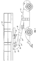
- a long side 44 of the rectangular platform 40 is generally aligned with the longitudinal axis of the boom 20 and support 10, the boom and platform being substantially lowered toward and near a full lowered position in which the platform will be centered above the boom which is aligned with and above the support structure for transport or storage.
- Fig. 2 is similar to Fig. 1 but shows the extensible sections 22, 24 of the boom 20 slightly extended and with the platform 40 positioned on the support beam 50 near the far left end limit of its travel along the support beam 50.
- Fig. 4 is similar to Fig.
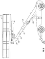
- Fig. 1 shows the boom 20 in an angularly elevated position with a short side 42 of the platform positioned parallel to the longitudinal axis of the support structure and with the support platform 40 near the right end limit of its travel along the support beam 50.
- Fig. 5 is similar to Fig. 4 but shows a long side 44 of the platform 40 extending parallel to the longitudinal axis of the support structure 10.
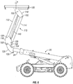
- Figs. 6 and 7 depict an apparatus for elevating and rotationally and longitudinally positioning a work platform, which does not form part of the claimed invention.
- a four bar linkage 110 replaces the platform support beam 50 and carriage 60 arrangement for longitudinally repositioning the platform 40 relative to the boom 20.
- the four bar linkage is comprised of spaced long bars 112 and 114 pivotally connected at their ends to spaced short bars 116 and 118, the pivotal connections of the four bars to each other being shown at 120.
- Short bar 116 of the four bar linkage is pivotally connected at 152 to end bracket 126 of the boom.
- a rotatable platform bearing 130 preferably located at or near the geometric center of the platform 40 is affixed to the platform 40 and to or near the upper end of the second support bar 118 to permit rotation of the platform 40 about a vertical axis to alternatively present a short or a long side of the rectangular work platform to a work area when desired.
- a powered means (not shown) preferably is provided for powered rotation of the platform as desired.
- a second powered means 140 shown in the form of a piston/cylinder unit having opposite ends pivotally connected near and to opposite ends of the long bars 112, 114 of the four bar linkage is provided for laterally translating the platform 40 relative to the boom.
- a suitable control arrangement may be provided so that the platform 40 can be longitudinally and rotationally positioned by personnel on the platform by controlling the rotary connection 130 and the translating piston/cylinder unit 140.
Description
- This disclosure pertains to aerial deck and work platforms which are mounted on single or multi-section telescopic or articulated booms to position the platform at a selected elevation and position relative to a chassis or other support structure. More specifically, the disclosure pertains to apparatus which is more efficiently able to position large sized work platforms with telescopic booms although articulated booms can also be used instead.
- Boom mounted work platforms are typically of rectangular configuration and, frequently, it is desirable to position the long side of the rectangular platform in close proximity to a vertical wall or to the vertical edge of a horizontal deck. Ideally, this should be easily accomplished without having to reposition an entire mobile vehicle on which the boom and work platform is supported.
- One prior art example of a telescopic boom having a large work platform non-rotatably supported thereon is the Manitou 150 TP which has a relatively short platform supported slide out deck which overlaps the main deck of the platform when the slide out deck is retracted.
- A second example of known prior art is the Nagano NUZ090D device in which a rectangular work platform of about 7 feet by 10.5 feet is mounted at the upper end of a telescopic boom for rotation about a vertical axis relative to the boom. Although the platform can be rotated, it cannot be laterally translated relative to the boom. The long sides of the work platform in this device are ordinarily aligned parallel to the longitudinal axis of the mobile support on which the boom is mounted.
-
EP 1 491 489 A2 discloses an apparatus according to the preamble of claim 1. Rotation of a large work platform relative to the boom creates very large torsional forces on the supporting boom which require substantial additional structural strength. The prior art platforms have therefore been limited in size by either using a rotatable platform while ensuring that the vertical axis of rotation of the platform is not located too far from a centered position over a mobile support structure or by merely precluding rotation of the platform relative to the boom and using a small slidable deck instead. - A more efficient arrangement is desired which is capable of longitudinal and rotational positioning for large workloads and in which the work platform and supporting boom may be closely positioned and stowed over the support structure, usually a mobile wheeled vehicle, during movement to different work locations.
- The present invention provides apparatus for elevating and positioning a work platform comprising a support structure which can comprise a mobile vehicle or chassis and a boom which may be telescopic connected to said support structure. The boom has a platform support end and a platform support beam pivotally connected to the platform support end of the boom. A first powered means is connected to the platform support beam and boom for maintaining the platform support beam in a substantially horizontal position during elevation and lowering of said boom. A carriage is mounted for sliding movement along the support beam and a platform is mounted on the carriage in a manner permitting rotation of the platform about a substantially vertical axis. Second powered means are provided for longitudinally moving the carriage and platform to different positions along the support beam and third powered means are provided for rotating the platform about a substantially vertical axis.
- Said platform is mounted on said carriage using a bearing arrangement positioned at a location at the geometric center of the platform for rotation of the platform relative to the carriage.
-
-
Figure 1 is a schematic side elevation view of a first embodiment of an apparatus for elevating and positioning a work platform and a large work platform; -
Figure 2 is a view similar toFig. 1 but showing the platform elevated to a working location; -
Figure 3 is a perspective view of the underside of the platform in an elevated position showing a platform support carriage positioned on a platform support beam; -
Figure 4 is a perspective view showing the platform in elevated position in-line with the chassis; -
Figure 5 is a side elevation view showing the platform in elevated position with the platform rotated to present the long side of the platform in the front direction; -
Figure 6 is a side elevation view of an example which does not form part of the invention, employing a four bar linkage for translating the platform beyond the end of the boom; and -
Figure 7 is a perspective view of the underside of the platform ofFig. 6 . - As seen in
Fig. 1 , the apparatus includes asupport structure 10. Preferably, thesupport structure 10 is a mobile vehicle which, as shown, may be a wheeled vehicle or a tracked vehicle. Such a vehicle may be motor driven or otherwise moveable to a desired position at a work location. Aboom 20, preferably telescopic and having one or moreextendable boom sections support structure 10 by a pivotal connection 30 (Fig. 4 ) which permits angular movement of the boom relative to the support structure about a substantially horizontal axis. As shown in the drawings, arectangular work platform 40 which may be elevated and laterally positioned relative to theboom 20 is shown above aplatform support beam 50. As will be appreciated by those skilled in the art, theplatform support beam 50 may take any structurally suitable configuration such as an I-beam, box beam, channel or other shape. - As shown, the
boom 20 may include a boomtop bracket 26 suitably configured for pivotal connection of theplatform support beam 50 to the boomtop bracket 26 by a pivotal connection shown at 52. A first poweredmeans 54 is connected to theplatform support beam 50 and to theboom 20 at theend bracket 26 for maintaining theplatform support beam 50 in a substantially horizontal position during elevation and lowering of theboom 20. In the embodiment shown inFig. 1 , the first poweredmeans 54 is depicted as a piston/cylinder unit having apivotal connection 56 to theboom bracket 26 and a secondpivotal connection 58 to theslider beam 50 as shown. Although the first poweredmeans 54 shown in the drawings comprises a piston/cylinder unit which may be hydraulic or pneumatic, the first powered means can of course take other forms such as a motor and transmission connected between theboom 20 and thesupport beam 50 operably functioning to maintain thesupport beam 50 in a generally level horizontal orientation as workers and/or equipment are being elevated and lowered on theplatform 40 by elevation and lowering of the boom which by either or a combination of the angular adjustment of the boom about thepivot 30 and extension or retraction of one or more of theboom sections - A
carriage 60 is mounted on thesupport beam 50 in a manner permitting longitudinal movement of thecarriage 60 between limits of travel along the length of thesupport beam 50. Thecarriage 60 may be supported on thebeam 50 in any suitable fashion such as by rollers (not shown) which ride along a suitable surface or surfaces of thesupport beam 50 which have a horizontal extent such as a top surface or lower of thesupport beam 50 or upper faces of horizontally extending flanges on thesupport beam 50. - A
work platform 40 is rotatably connected to thecarriage 60 using a bearing arrangement postioned at a location at the geometric center of the platform in a manner to permit rotation of theplatform 40 about a substantially vertical axis. The bearing may be connected to theplatform 40 andcarriage 60 by any suitable means such as threaded connectors or welding. - In
Fig. 3 , a second powered means is mounted on thecarriage 60 for longitudinally moving the carriage to different positions along thesupport beam 50. As shown, the second powered means includes a hydraulic motor ormotors 72 for driving a pinion gear or gears suitable for engaging a rack gear or rack gears mounted on thesupport beam 50 to move thecarriage 60 longitudinally along the support beam as desired. As will be appreciated by those skilled in the art, suitable control of the second powered means, accessible by personnel on thework platform 40 will be provided. The details of the carriage positioning control are not shown and may be easily provided by those with reasonable skill in the art. - Also shown in
Fig. 3 is a third powered means, generally indicated at 90, for rotating theplatform 40 about a substantially vertical axis when desired. The third powered means 90 may comprise a motor and transmission of any suitable type, preferably hydraulic. In the presently preferred arrangement shown inFig. 4 , the transmission includes a drive gear (not shown) engageable with a driven gear shown at 92. The third powered means 90 for rotating the platform relative to the carriage should also be controllable by personnel on thework platform 40 whereby personnel on thework platform 40 can both rotate the platform about a substantially vertical axis relative to theplatform support beam 50 and laterally position theplatform 40 at selected working locations relative to theplatform support beam 50. This enables workers to rotate and translate the platform as desired such that the long side of the platform may be positioned outwardly well beyond the footprint of thesupport structure 10 underneath. In many job sites, it is impossible or highly difficult to position a work platform close enough to a vertical wall other than by placing the longitudinal axis of the vehicle parallel and close to the wall. This is particularly true if the boom is telescopic and is mounted on the support vehicle for rotation only around a horizontal axis transverse to the vehicle length. The structure disclosed herein can easily accommodate a very large platform of approximately 7.5 feet by 22 feet which can rotate relative to the telescopic boom on which it is supported to present a long side to the work area when desired and hence allow the support vehicle to approach the work at any angle. Significantly larger loads (typically twice the capacity of existing machines) can be supported on a large platform that can be rotated, without imparting substantial torsional loads into the telescopic boom structure. - As is conventional, the
boom 20 is angularly elevated and lowered relative to thesupport structure 10 by a fourth poweredmeans 100 which, as shown, is in the form of a hydraulic piston/cylinder arrangement. As will be appreciated by those skilled in the art, although the fourth poweredmeans 100 is depicted as a hydraulic piston/cylinder unit, it should be apparent that the fourth poweredmeans 100 can take any other suitable form for achieving the intended purpose, such as a pneumatic piston/cylinder unit, and electric or fluid driven motor/transmission units and others. Also, as will be appreciated by those skilled in the art, a fifth powered means (not shown) will be provided for extending and retracting theextensible sections telescopic boom 20. - In
Fig. 1 , along side 44 of therectangular platform 40 is generally aligned with the longitudinal axis of theboom 20 and support 10, the boom and platform being substantially lowered toward and near a full lowered position in which the platform will be centered above the boom which is aligned with and above the support structure for transport or storage.Fig. 2 is similar toFig. 1 but shows theextensible sections boom 20 slightly extended and with theplatform 40 positioned on thesupport beam 50 near the far left end limit of its travel along thesupport beam 50.Fig. 4 is similar toFig. 1 but shows theboom 20 in an angularly elevated position with ashort side 42 of the platform positioned parallel to the longitudinal axis of the support structure and with thesupport platform 40 near the right end limit of its travel along thesupport beam 50.Fig. 5 is similar toFig. 4 but shows along side 44 of theplatform 40 extending parallel to the longitudinal axis of thesupport structure 10. -
Figs. 6 and7 depict an apparatus for elevating and rotationally and longitudinally positioning a work platform, which does not form part of the claimed invention. In the embodiment ofFigs. 6 and7 , a fourbar linkage 110 replaces theplatform support beam 50 andcarriage 60 arrangement for longitudinally repositioning theplatform 40 relative to theboom 20. The four bar linkage is comprised of spacedlong bars short bars Short bar 116 of the four bar linkage is pivotally connected at 152 to endbracket 126 of the boom. A rotatable platform bearing 130 preferably located at or near the geometric center of theplatform 40 is affixed to theplatform 40 and to or near the upper end of thesecond support bar 118 to permit rotation of theplatform 40 about a vertical axis to alternatively present a short or a long side of the rectangular work platform to a work area when desired. As described with reference to the first embodiment, a powered means (not shown) preferably is provided for powered rotation of the platform as desired. - A first powered means 154 similar to the first powered means 54 of the first embodiment, shown in the form of a piston/cylinder unit, is pivotally connected at 156 to the
boom end bracket 126 and to the four bar linkage at 158 to maintain theplatform 40 in a substantially horizontal orientation at all relevant times. A second powered means 140, shown in the form of a piston/cylinder unit having opposite ends pivotally connected near and to opposite ends of thelong bars platform 40 relative to the boom. As in the first embodiment, a suitable control arrangement may be provided so that theplatform 40 can be longitudinally and rotationally positioned by personnel on the platform by controlling therotary connection 130 and the translating piston/cylinder unit 140. - Various modifications of the embodiments of the invention shown and described above may be made without departing from the scope of the invention which is defined by the claims which follow.
Claims (4)
- Apparatus for elevating and positioning a work platform comprising:a) a support structure (10);b) a boom (20) connected to said support structure, said boom having a platform support end;c) a platform support beam pivotally connected to said platform support end of said boom;d) first powered means connected to said platform support beam and said boom for maintaining said platform support beam in a substantially horizontal position during elevation and lowering of said boom;e) a carriage (60) mounted for sliding movement along said support beam;f) a platform (40) mounted on said carriage (60) for rotation of said platform about a substantially vertical axis relative to said carriage (60);g) second powered means (72) for moving said carriage and platform to different positions along said support beam; andh) third powered means (90) for rotating said platform about said substantially vertical axis, characterized in thatsaid platform (40) is mounted on said carriage (60) using a bearing arrangement positioned at a location at the geometric center of the platform for rotation of the platform (40) relative to the carriage (60).
- The apparatus of claim 1, wherein said support structure is a mobile chassis having a longitudinal axis and said boom is connected to said chassis by a pivotal connection for rotation of said boom about a substantially horizontal axis transverse to said longitudinal axis.
- The apparatus of claim 2, further comprising fourth powered means for moving said boom about said horizontal axis, wherein said mobile support structure is a wheeled vehicle.
- The apparatus of claim 1 characterized in that said support structure is a wheeled vehicle and said boom is a telescopic boom connected to said support structure by a pivotal connection for rotation of said boom about a substantially horizontal axis and further comprising fourth powered means for rotating said boom about said horizontal axis.
Applications Claiming Priority (1)
| Application Number | Priority Date | Filing Date | Title |
|---|---|---|---|
| US20458509P | 2009-01-08 | 2009-01-08 |
Publications (3)
| Publication Number | Publication Date |
|---|---|
| EP2206675A2 EP2206675A2 (en) | 2010-07-14 |
| EP2206675A3 EP2206675A3 (en) | 2010-09-22 |
| EP2206675B1 true EP2206675B1 (en) | 2018-09-26 |
Family
ID=42109812
Family Applications (1)
| Application Number | Title | Priority Date | Filing Date |
|---|---|---|---|
| EP09178135.1A Active EP2206675B1 (en) | 2009-01-08 | 2009-12-07 | Apparatus for elevating and positioning a work platform |
Country Status (4)
| Country | Link |
|---|---|
| US (1) | US8631902B2 (en) |
| EP (1) | EP2206675B1 (en) |
| JP (1) | JP2010159624A (en) |
| CA (1) | CA2686985C (en) |
Families Citing this family (18)
| Publication number | Priority date | Publication date | Assignee | Title |
|---|---|---|---|---|
| US8899901B2 (en) * | 2012-06-14 | 2014-12-02 | Warrior Energy Services Corporation | Pipe handling apparatus and method |
| CN103058104B (en) * | 2012-12-06 | 2016-03-30 | 长沙中联消防机械有限公司 | Aerial platform and working bucket leveling mechanism thereof |
| CN105452099A (en) * | 2013-06-07 | 2016-03-30 | 弗朗西斯科·奥泰利 | Apparatus for transferring people and/or goods to or from a vessel |
| CN103495267B (en) * | 2013-10-11 | 2015-12-16 | 徐州重型机械有限公司 | Telescopic arm arm head jockey, for the telescopic arm of fire fighting truck and fire fighting truck |
| USD773146S1 (en) * | 2014-02-28 | 2016-11-29 | Haulotte Group | Boom lift |
| US10399834B2 (en) * | 2014-08-04 | 2019-09-03 | Almac S.R.L. | Levelling group for aerial work platforms |
| CN104528607B (en) * | 2014-12-28 | 2016-12-14 | 浙江鼎力机械股份有限公司 | A kind of platform assembly of bridge-type job platform |
| CN104528609B (en) * | 2014-12-28 | 2017-02-22 | 浙江鼎力机械股份有限公司 | Bridge type operation platform |
| WO2016176782A1 (en) * | 2015-05-07 | 2016-11-10 | Linepro Equipment Ltd. | Self-levelling attachment carriage for a boom assembly |
| US20180132477A1 (en) * | 2016-11-16 | 2018-05-17 | ADC Custom Products, LLC | Transportable Observation Station |
| US10991279B1 (en) | 2017-04-06 | 2021-04-27 | Kooima Ag, Inc. | Mobile elevating apparatus |
| US10467932B1 (en) | 2017-04-06 | 2019-11-05 | Kooima Company | Mobile elevating apparatus |
| CN108714885B (en) * | 2018-06-22 | 2024-03-29 | 徐州海伦哲专用车辆股份有限公司 | High-altitude electrified operation robot and operation method |
| USD981075S1 (en) * | 2020-05-22 | 2023-03-14 | Jiangsu Xcmg Construction Machinery Research Institute Ltd. | Aerial platform truck |
| US20210372201A1 (en) * | 2020-06-01 | 2021-12-02 | Utilicor Technologies Inc. | Excavation apparatus with supporting linkage |
| CN113073833B (en) * | 2021-04-09 | 2024-03-08 | 河南润禾建筑工程有限公司 | Support for civil engineering |
| CN113565303A (en) * | 2021-08-09 | 2021-10-29 | 山东滕建建设集团有限公司 | Adjustable that construction was used bears frame structure |
| CN115215251A (en) * | 2022-07-14 | 2022-10-21 | 浙江新发电机股份有限公司 | Transportation positioning tool for large motor production |
Family Cites Families (27)
| Publication number | Priority date | Publication date | Assignee | Title |
|---|---|---|---|---|
| US3190391A (en) * | 1963-12-02 | 1965-06-22 | Utility Body Company | Safety device for a basket |
| US3709322A (en) * | 1971-02-01 | 1973-01-09 | M Mitchell | Overhead service apparatus with swivel platform |
| US3834488A (en) * | 1972-11-06 | 1974-09-10 | J Grove | Aerial platform with articulating jib |
| US3893540A (en) * | 1973-12-07 | 1975-07-08 | Robert A Beucher | Lifting mechanism |
| FR2266656A1 (en) | 1974-04-03 | 1975-10-31 | Gacquerelle Gerard | Mobile overhead working platform - has boom with parallelogram linkage supporting slewing and sliding platform |
| US4019604A (en) * | 1975-06-16 | 1977-04-26 | Fabtek, Inc. | Elevating platform apparatus |
| US4271926A (en) * | 1980-02-04 | 1981-06-09 | Mark Industries | Rotatable work platform |
| US4456093A (en) * | 1981-06-16 | 1984-06-26 | Interstate Electronics Corp. | Control system for aerial work platform machine and method of controlling an aerial work platform machine |
| US4511015A (en) * | 1983-06-15 | 1985-04-16 | Purdy Paul J | Manlift |
| US4690247A (en) * | 1985-03-14 | 1987-09-01 | Nippon Light Metal Co., Ltd. | Inspection car for bridge construction of a high level road |
| US4757875A (en) * | 1987-09-25 | 1988-07-19 | Kidde, Inc. | Vehicular low profile self propelled aerial work platform |
| US4775029A (en) * | 1987-10-08 | 1988-10-04 | Jlg Industries, Inc. | Collapsible tower boom lift |
| FR2626865B1 (en) | 1988-02-04 | 1990-04-20 | Couturier Sa Fils Marcel | PLATFORM FOR TELESCOPIC BOOM OF LIFTING MACHINE |
| US5082085A (en) * | 1990-08-30 | 1992-01-21 | Up-Right, Inc. | Platform leveling apparatus |
| DE4120584A1 (en) | 1991-06-21 | 1992-12-24 | Josef Albrecht | Platform attachment for mobile digger jib arm - has height and tilt adjustment with tilt adjustment facilitated by means of double acting hydraulic cylinder |
| DE4123398A1 (en) | 1991-07-15 | 1993-01-21 | Spezialfahrzeugaufbau Und Kabe | MOBILE WORKSTAGE WITH FLEXIBLE WORKING POSITION |
| US5159989A (en) * | 1991-10-09 | 1992-11-03 | Up-Right International Manufacturing, Ltd. | Automatic hydraulic leveling system |
| US5427197A (en) * | 1992-12-07 | 1995-06-27 | Waters; David | Pruning system |
| FR2701940B1 (en) | 1993-02-26 | 1995-05-19 | Eurl Garage Landes | Mobile work platform. |
| US5269393A (en) * | 1993-04-22 | 1993-12-14 | T.G. Industries Inc. | Brake mechanism for a boom supported occupant bucket |
| US5913379A (en) * | 1996-01-26 | 1999-06-22 | Figgie International, Inc. | Articulated aerial work platform system |
| CA2177508C (en) * | 1996-05-28 | 2001-03-20 | George Leslie Lawson | Mobile lift assembly |
| US6119882A (en) * | 1998-12-04 | 2000-09-19 | Upright, Inc. | Self-propelled boom with extendible axles |
| US6488161B1 (en) * | 2000-05-02 | 2002-12-03 | Jlg Industries, Inc. | Boom mechanism |
| ITVR20030081A1 (en) | 2003-06-23 | 2004-12-24 | Silvano Leoni | AERIAL PLATFORM APPLICABLE ON LIFTING AND / OR EQUIPMENT |
| US7246684B2 (en) * | 2004-02-26 | 2007-07-24 | Jlg Industries, Inc. | Boom lift vehicle and method of controlling boom angles |
| US7448470B2 (en) * | 2005-09-06 | 2008-11-11 | Aluminum Ladder Company | Maintenance stand |
-
2009
- 2009-11-11 US US12/616,350 patent/US8631902B2/en active Active
- 2009-12-03 CA CA2686985A patent/CA2686985C/en active Active
- 2009-12-07 EP EP09178135.1A patent/EP2206675B1/en active Active
- 2009-12-15 JP JP2009284368A patent/JP2010159624A/en active Pending
Non-Patent Citations (1)
| Title |
|---|
| None * |
Also Published As
| Publication number | Publication date |
|---|---|
| EP2206675A2 (en) | 2010-07-14 |
| CA2686985A1 (en) | 2010-07-08 |
| JP2010159624A (en) | 2010-07-22 |
| EP2206675A3 (en) | 2010-09-22 |
| CA2686985C (en) | 2017-03-07 |
| US8631902B2 (en) | 2014-01-21 |
| US20100170747A1 (en) | 2010-07-08 |
Similar Documents
| Publication | Publication Date | Title |
|---|---|---|
| EP2206675B1 (en) | Apparatus for elevating and positioning a work platform | |
| CN107226438B (en) | Tunnel inspection operation device | |
| CA2440788C (en) | Motorized scaffold with displaceable worker support platform | |
| US4019604A (en) | Elevating platform apparatus | |
| EP1084987B1 (en) | Retractable counterweight for straight-boom aerial work platform | |
| US9969558B1 (en) | Portable multi-sectioned boom concrete conveyor assembly | |
| US20190316367A1 (en) | Mason's adjustable chimney-platform arrangement | |
| CN104528609A (en) | Bridge type operation platform | |
| US8327950B2 (en) | Excavation apparatus | |
| US9657524B2 (en) | Drilling apparatus | |
| KR101008221B1 (en) | High-place worktable for agriculture | |
| US6378652B1 (en) | Lateral jib for vertical mast mobile elevating work platform | |
| CN104512843A (en) | Working platform of bridge type working platform | |
| CA1075225A (en) | Downcrowding boom assembly | |
| GB2536664A (en) | Two-sided fork lift apparatus | |
| US7862285B1 (en) | Compressor trolley | |
| US11597435B2 (en) | Drilling rig | |
| RU2312965C2 (en) | Construction machine | |
| US4348008A (en) | Lifting apparatus | |
| EP4303170A1 (en) | Mobility mule | |
| CN217680643U (en) | Elevating gear is used in heating engineering construction | |
| US11745952B1 (en) | Multi-sectioned boom conveyor assembly having hinged telescoping boom section | |
| CN212024705U (en) | Height-adjustable double-operation platform | |
| CN211688107U (en) | Emergency disposal device for dangerous road section of steep slope | |
| CN113898388A (en) | Self-moving tail is with removing anchor protection device and anchor protection system |
Legal Events
| Date | Code | Title | Description |
|---|---|---|---|
| PUAI | Public reference made under article 153(3) epc to a published international application that has entered the european phase |
Free format text: ORIGINAL CODE: 0009012 |
|
| AK | Designated contracting states |
Kind code of ref document: A2 Designated state(s): AT BE BG CH CY CZ DE DK EE ES FI FR GB GR HR HU IE IS IT LI LT LU LV MC MK MT NL NO PL PT RO SE SI SK SM TR |
|
| PUAL | Search report despatched |
Free format text: ORIGINAL CODE: 0009013 |
|
| AK | Designated contracting states |
Kind code of ref document: A3 Designated state(s): AT BE BG CH CY CZ DE DK EE ES FI FR GB GR HR HU IE IS IT LI LT LU LV MC MK MT NL NO PL PT RO SE SI SK SM TR |
|
| 17P | Request for examination filed |
Effective date: 20110316 |
|
| 17Q | First examination report despatched |
Effective date: 20130730 |
|
| GRAP | Despatch of communication of intention to grant a patent |
Free format text: ORIGINAL CODE: EPIDOSNIGR1 |
|
| INTG | Intention to grant announced |
Effective date: 20180613 |
|
| GRAS | Grant fee paid |
Free format text: ORIGINAL CODE: EPIDOSNIGR3 |
|
| GRAA | (expected) grant |
Free format text: ORIGINAL CODE: 0009210 |
|
| AK | Designated contracting states |
Kind code of ref document: B1 Designated state(s): AT BE BG CH CY CZ DE DK EE ES FI FR GB GR HR HU IE IS IT LI LT LU LV MC MK MT NL NO PL PT RO SE SI SK SM TR |
|
| REG | Reference to a national code |
Ref country code: GB Ref legal event code: FG4D |
|
| REG | Reference to a national code |
Ref country code: CH Ref legal event code: EP |
|
| REG | Reference to a national code |
Ref country code: AT Ref legal event code: REF Ref document number: 1045766 Country of ref document: AT Kind code of ref document: T Effective date: 20181015 |
|
| REG | Reference to a national code |
Ref country code: IE Ref legal event code: FG4D |
|
| REG | Reference to a national code |
Ref country code: DE Ref legal event code: R096 Ref document number: 602009054718 Country of ref document: DE |
|
| REG | Reference to a national code |
Ref country code: NL Ref legal event code: FP |
|
| REG | Reference to a national code |
Ref country code: SE Ref legal event code: TRGR |
|
| PG25 | Lapsed in a contracting state [announced via postgrant information from national office to epo] |
Ref country code: GR Free format text: LAPSE BECAUSE OF FAILURE TO SUBMIT A TRANSLATION OF THE DESCRIPTION OR TO PAY THE FEE WITHIN THE PRESCRIBED TIME-LIMIT Effective date: 20181227 Ref country code: FI Free format text: LAPSE BECAUSE OF FAILURE TO SUBMIT A TRANSLATION OF THE DESCRIPTION OR TO PAY THE FEE WITHIN THE PRESCRIBED TIME-LIMIT Effective date: 20180926 Ref country code: NO Free format text: LAPSE BECAUSE OF FAILURE TO SUBMIT A TRANSLATION OF THE DESCRIPTION OR TO PAY THE FEE WITHIN THE PRESCRIBED TIME-LIMIT Effective date: 20181226 Ref country code: LT Free format text: LAPSE BECAUSE OF FAILURE TO SUBMIT A TRANSLATION OF THE DESCRIPTION OR TO PAY THE FEE WITHIN THE PRESCRIBED TIME-LIMIT Effective date: 20180926 Ref country code: BG Free format text: LAPSE BECAUSE OF FAILURE TO SUBMIT A TRANSLATION OF THE DESCRIPTION OR TO PAY THE FEE WITHIN THE PRESCRIBED TIME-LIMIT Effective date: 20181226 |
|
| REG | Reference to a national code |
Ref country code: LT Ref legal event code: MG4D |
|
| PG25 | Lapsed in a contracting state [announced via postgrant information from national office to epo] |
Ref country code: HR Free format text: LAPSE BECAUSE OF FAILURE TO SUBMIT A TRANSLATION OF THE DESCRIPTION OR TO PAY THE FEE WITHIN THE PRESCRIBED TIME-LIMIT Effective date: 20180926 Ref country code: LV Free format text: LAPSE BECAUSE OF FAILURE TO SUBMIT A TRANSLATION OF THE DESCRIPTION OR TO PAY THE FEE WITHIN THE PRESCRIBED TIME-LIMIT Effective date: 20180926 |
|
| REG | Reference to a national code |
Ref country code: AT Ref legal event code: MK05 Ref document number: 1045766 Country of ref document: AT Kind code of ref document: T Effective date: 20180926 |
|
| PG25 | Lapsed in a contracting state [announced via postgrant information from national office to epo] |
Ref country code: IS Free format text: LAPSE BECAUSE OF FAILURE TO SUBMIT A TRANSLATION OF THE DESCRIPTION OR TO PAY THE FEE WITHIN THE PRESCRIBED TIME-LIMIT Effective date: 20190126 Ref country code: AT Free format text: LAPSE BECAUSE OF FAILURE TO SUBMIT A TRANSLATION OF THE DESCRIPTION OR TO PAY THE FEE WITHIN THE PRESCRIBED TIME-LIMIT Effective date: 20180926 Ref country code: PL Free format text: LAPSE BECAUSE OF FAILURE TO SUBMIT A TRANSLATION OF THE DESCRIPTION OR TO PAY THE FEE WITHIN THE PRESCRIBED TIME-LIMIT Effective date: 20180926 Ref country code: CZ Free format text: LAPSE BECAUSE OF FAILURE TO SUBMIT A TRANSLATION OF THE DESCRIPTION OR TO PAY THE FEE WITHIN THE PRESCRIBED TIME-LIMIT Effective date: 20180926 Ref country code: ES Free format text: LAPSE BECAUSE OF FAILURE TO SUBMIT A TRANSLATION OF THE DESCRIPTION OR TO PAY THE FEE WITHIN THE PRESCRIBED TIME-LIMIT Effective date: 20180926 Ref country code: RO Free format text: LAPSE BECAUSE OF FAILURE TO SUBMIT A TRANSLATION OF THE DESCRIPTION OR TO PAY THE FEE WITHIN THE PRESCRIBED TIME-LIMIT Effective date: 20180926 Ref country code: IT Free format text: LAPSE BECAUSE OF FAILURE TO SUBMIT A TRANSLATION OF THE DESCRIPTION OR TO PAY THE FEE WITHIN THE PRESCRIBED TIME-LIMIT Effective date: 20180926 Ref country code: EE Free format text: LAPSE BECAUSE OF FAILURE TO SUBMIT A TRANSLATION OF THE DESCRIPTION OR TO PAY THE FEE WITHIN THE PRESCRIBED TIME-LIMIT Effective date: 20180926 |
|
| PG25 | Lapsed in a contracting state [announced via postgrant information from national office to epo] |
Ref country code: SM Free format text: LAPSE BECAUSE OF FAILURE TO SUBMIT A TRANSLATION OF THE DESCRIPTION OR TO PAY THE FEE WITHIN THE PRESCRIBED TIME-LIMIT Effective date: 20180926 Ref country code: PT Free format text: LAPSE BECAUSE OF FAILURE TO SUBMIT A TRANSLATION OF THE DESCRIPTION OR TO PAY THE FEE WITHIN THE PRESCRIBED TIME-LIMIT Effective date: 20190126 Ref country code: SK Free format text: LAPSE BECAUSE OF FAILURE TO SUBMIT A TRANSLATION OF THE DESCRIPTION OR TO PAY THE FEE WITHIN THE PRESCRIBED TIME-LIMIT Effective date: 20180926 |
|
| REG | Reference to a national code |
Ref country code: DE Ref legal event code: R097 Ref document number: 602009054718 Country of ref document: DE |
|
| PG25 | Lapsed in a contracting state [announced via postgrant information from national office to epo] |
Ref country code: DK Free format text: LAPSE BECAUSE OF FAILURE TO SUBMIT A TRANSLATION OF THE DESCRIPTION OR TO PAY THE FEE WITHIN THE PRESCRIBED TIME-LIMIT Effective date: 20180926 |
|
| REG | Reference to a national code |
Ref country code: CH Ref legal event code: PL |
|
| PLBE | No opposition filed within time limit |
Free format text: ORIGINAL CODE: 0009261 |
|
| STAA | Information on the status of an ep patent application or granted ep patent |
Free format text: STATUS: NO OPPOSITION FILED WITHIN TIME LIMIT |
|
| PG25 | Lapsed in a contracting state [announced via postgrant information from national office to epo] |
Ref country code: LU Free format text: LAPSE BECAUSE OF NON-PAYMENT OF DUE FEES Effective date: 20181207 Ref country code: MC Free format text: LAPSE BECAUSE OF FAILURE TO SUBMIT A TRANSLATION OF THE DESCRIPTION OR TO PAY THE FEE WITHIN THE PRESCRIBED TIME-LIMIT Effective date: 20180926 |
|
| 26N | No opposition filed |
Effective date: 20190627 |
|
| REG | Reference to a national code |
Ref country code: IE Ref legal event code: MM4A |
|
| REG | Reference to a national code |
Ref country code: BE Ref legal event code: MM Effective date: 20181231 |
|
| PG25 | Lapsed in a contracting state [announced via postgrant information from national office to epo] |
Ref country code: SI Free format text: LAPSE BECAUSE OF FAILURE TO SUBMIT A TRANSLATION OF THE DESCRIPTION OR TO PAY THE FEE WITHIN THE PRESCRIBED TIME-LIMIT Effective date: 20180926 Ref country code: IE Free format text: LAPSE BECAUSE OF NON-PAYMENT OF DUE FEES Effective date: 20181207 |
|
| PG25 | Lapsed in a contracting state [announced via postgrant information from national office to epo] |
Ref country code: BE Free format text: LAPSE BECAUSE OF NON-PAYMENT OF DUE FEES Effective date: 20181231 |
|
| PG25 | Lapsed in a contracting state [announced via postgrant information from national office to epo] |
Ref country code: CH Free format text: LAPSE BECAUSE OF NON-PAYMENT OF DUE FEES Effective date: 20181231 Ref country code: LI Free format text: LAPSE BECAUSE OF NON-PAYMENT OF DUE FEES Effective date: 20181231 |
|
| PG25 | Lapsed in a contracting state [announced via postgrant information from national office to epo] |
Ref country code: MT Free format text: LAPSE BECAUSE OF NON-PAYMENT OF DUE FEES Effective date: 20181207 |
|
| PG25 | Lapsed in a contracting state [announced via postgrant information from national office to epo] |
Ref country code: TR Free format text: LAPSE BECAUSE OF FAILURE TO SUBMIT A TRANSLATION OF THE DESCRIPTION OR TO PAY THE FEE WITHIN THE PRESCRIBED TIME-LIMIT Effective date: 20180926 |
|
| PG25 | Lapsed in a contracting state [announced via postgrant information from national office to epo] |
Ref country code: CY Free format text: LAPSE BECAUSE OF FAILURE TO SUBMIT A TRANSLATION OF THE DESCRIPTION OR TO PAY THE FEE WITHIN THE PRESCRIBED TIME-LIMIT Effective date: 20180926 Ref country code: HU Free format text: LAPSE BECAUSE OF FAILURE TO SUBMIT A TRANSLATION OF THE DESCRIPTION OR TO PAY THE FEE WITHIN THE PRESCRIBED TIME-LIMIT; INVALID AB INITIO Effective date: 20091207 Ref country code: MK Free format text: LAPSE BECAUSE OF NON-PAYMENT OF DUE FEES Effective date: 20180926 |
|
| REG | Reference to a national code |
Ref country code: DE Ref legal event code: R082 Ref document number: 602009054718 Country of ref document: DE Representative=s name: MEISSNER BOLTE PATENTANWAELTE RECHTSANWAELTE P, DE |
|
| PGFP | Annual fee paid to national office [announced via postgrant information from national office to epo] |
Ref country code: GB Payment date: 20231208 Year of fee payment: 15 |
|
| PGFP | Annual fee paid to national office [announced via postgrant information from national office to epo] |
Ref country code: SE Payment date: 20231218 Year of fee payment: 15 Ref country code: NL Payment date: 20231221 Year of fee payment: 15 Ref country code: FR Payment date: 20231109 Year of fee payment: 15 Ref country code: DE Payment date: 20231211 Year of fee payment: 15 |