EP2206614A1 - Valve device, vehicle tyre pressure measuring unit and vehicle tyre pressure system - Google Patents
Valve device, vehicle tyre pressure measuring unit and vehicle tyre pressure system Download PDFInfo
- Publication number
- EP2206614A1 EP2206614A1 EP09010677A EP09010677A EP2206614A1 EP 2206614 A1 EP2206614 A1 EP 2206614A1 EP 09010677 A EP09010677 A EP 09010677A EP 09010677 A EP09010677 A EP 09010677A EP 2206614 A1 EP2206614 A1 EP 2206614A1
- Authority
- EP
- European Patent Office
- Prior art keywords
- valve
- tire pressure
- pressure measuring
- antenna
- main body
- Prior art date
- Legal status (The legal status is an assumption and is not a legal conclusion. Google has not performed a legal analysis and makes no representation as to the accuracy of the status listed.)
- Withdrawn
Links
Images
Classifications
-
- B—PERFORMING OPERATIONS; TRANSPORTING
- B60—VEHICLES IN GENERAL
- B60C—VEHICLE TYRES; TYRE INFLATION; TYRE CHANGING; CONNECTING VALVES TO INFLATABLE ELASTIC BODIES IN GENERAL; DEVICES OR ARRANGEMENTS RELATED TO TYRES
- B60C23/00—Devices for measuring, signalling, controlling, or distributing tyre pressure or temperature, specially adapted for mounting on vehicles; Arrangement of tyre inflating devices on vehicles, e.g. of pumps or of tanks; Tyre cooling arrangements
- B60C23/02—Signalling devices actuated by tyre pressure
- B60C23/04—Signalling devices actuated by tyre pressure mounted on the wheel or tyre
- B60C23/0408—Signalling devices actuated by tyre pressure mounted on the wheel or tyre transmitting the signals by non-mechanical means from the wheel or tyre to a vehicle body mounted receiver
-
- B—PERFORMING OPERATIONS; TRANSPORTING
- B60—VEHICLES IN GENERAL
- B60C—VEHICLE TYRES; TYRE INFLATION; TYRE CHANGING; CONNECTING VALVES TO INFLATABLE ELASTIC BODIES IN GENERAL; DEVICES OR ARRANGEMENTS RELATED TO TYRES
- B60C23/00—Devices for measuring, signalling, controlling, or distributing tyre pressure or temperature, specially adapted for mounting on vehicles; Arrangement of tyre inflating devices on vehicles, e.g. of pumps or of tanks; Tyre cooling arrangements
- B60C23/02—Signalling devices actuated by tyre pressure
- B60C23/04—Signalling devices actuated by tyre pressure mounted on the wheel or tyre
- B60C23/0491—Constructional details of means for attaching the control device
- B60C23/0494—Valve stem attachments positioned inside the tyre chamber
Definitions
- the present invention relates generally to valves, and more particularly to a valve device and a tire pressure measurement module.
- the tire pressure measuring unit can, for example, transmit the pressure detected in the vehicle tire wirelessly to a central vehicle control system.
- the US patent US 6,799,455 B1 a tire pressure measuring unit in which a transmitter is connected to an antenna located inside the tire.
- the vehicle tire attenuates the radio signals outgoing from the antenna. Consequently, the transmission power of the tire pressure measuring unit must be correspondingly high so that, for example, the central vehicle controller can reliably receive the radio signals through the tire.
- this can lead to an increased energy consumption of the tire pressure measuring unit.
- the object of the present invention is to provide a valve device and a tire pressure measurement module that enables reliable, wireless transmission.
- the present invention provides a valve apparatus comprising: a valve main body made at least partially of an electrically conductive material, a tire pressure measuring device, and an antenna device, the tire pressure measuring device including an electromagnetic coupling element that electrically or electromagnetically communicates the tire pressure measuring device the antenna device couples.
- the present invention provides a tire pressure measurement module for a valve device according to the first aspect of the invention, comprising: a tire pressure measurement device, an antenna device, and a module housing; wherein the tire pressure measuring device has a coupling element which electrically or electromagnetically couples the tire pressure measuring device with the antenna device.
- Fig. 1 a first embodiment of a valve device in accordance with the present invention is illustrated. Before a detailed description first follows general explanations to the embodiments and their advantages.
- the pressure determined by a tire pressure measuring device is transmitted wirelessly, for example, to a central vehicle control system.
- a valve device typically includes a valve main body that receives a valve and may additionally receive, for example, a tire pressure gauge.
- the tire pressure measuring device measures the air pressure in the vehicle tire and transmits the measured air pressure wirelessly to a receiver, such as a central vehicle control.
- the antenna main body is formed of, for example, an electrically conductive material such as metal (e.g., aluminum) so that the valve main body can serve as a kind of Hertzian dipole or cavity radiator.
- valve body or parts of the valve body serve as an antenna
- the electromagnetic wave radiated from it can reach the receiver directly and do not have to penetrate the vehicle tire, as is the case, for example, for the initially mentioned prior art (US Pat. US 6,799,455 B1 ) suggests.
- the valve main body can serve as an antenna
- the radio signals from the tire pressure measuring device in the valve main body must be electrically or electromagnetically coupled.
- an electrical coupling element for example, the transmitting device of the tire pressure measuring device directly electrically with, for example.
- the bottom of the valve foot of the valve main body connects.
- the valve main body may also serve as an antenna.
- the coupling element does not directly (only) electrically couple the transmitting device of the tire pressure measuring device to the valve main body, but it couples the tire pressure measuring device with an antenna device which then emits electromagnetic waves, for example, which in turn couple into the valve main body.
- This coupling can be used as a direct electrical connection between the tire pressure measuring device, the transmitting device or an antenna output of the tire pressure measuring device, or for example be formed contactless as electromagnetic coupling to the antenna device.
- this in turn can serve as an antenna by radiating electromagnetic waves, for example, in the manner of a Hertzian dipole or cavity radiator, representing, for example, the measured tire pressure and then, for example. From a central Vehicle control can be received.
- the antenna device is disc-shaped in some embodiments and may, for example, have an opening.
- the antenna device forms a glass antenna which is suitable for emitting electromagnetic waves.
- the electromagnetic waves radiated by the antenna device at least partially couple into the valve main body, which not only receives the electromagnetic waves, but in turn radiates them.
- the glass antenna is, for example, arranged in the valve device such that the opening points in the direction of the valve main body.
- the antenna device is disc-shaped, in some embodiments a circular current is produced in the disk-shaped antenna device when the coupling element couples in a corresponding alternating current. If the antenna device has, for example, an opening, the antenna device can function similarly to a hollow radiator which is suitable for emitting electromagnetic radiation at an opening end, for example in the direction of the valve main body.
- the antenna device has a different shape that is suitable as an antenna, such as, for example, a meander-like shape, which then radiates dipole-like, for example, electromagnetic waves.
- the antenna device also serves as an electromagnetic coupling element that converts the alternating currents injected from the coupling element disposed between the transmitting device and the antenna device into electromagnetic waves and radiates them such that they can be received by the valve main body and in turn radiated by itself.
- the antenna device as an electromagnetic coupling element in some embodiments, for example, it is possible to arrange the tire pressure measuring device in a receiving area of the valve main body such that it lies at least partially between the valve main body and the antenna device. This simplifies the structure of the entire valve device, since the tire pressure measuring device having, for example, a circuit board, not with the coupling element and electronic components, which are provided for tire pressure detection, must be mounted in the direction of the valve main body, but, for example, in the opposite direction, away from the valve main body, oriented.
- the valve main body has two areas: a valve receiving area, which is, for example, configured as a tube, and serves to receive the actual valve and a second area, which adjoins the first and forms the valve foot.
- the valve foot may, for example, be cylindrical and have a diameter which is greater than that of the tubular valve receiving area.
- the valve foot is formed in some embodiments, a hollow cylinder and is, for example, suitable to at least partially receive the tire pressure measuring device. In this case, the transition between the tubular receiving portion for the valve and the cylindrical receiving portion for the tire pressure measuring device, for example, a bottom portion.
- the arrangement of the tire pressure measuring device is then, for example, between the bottom portion of the valve main body and, e.g. disc-shaped, antenna device arranged.
- the coupling element is thus arranged on the side of the tire pressure measuring device, which is averted from the valve main body.
- the tire pressure measuring device couples, via the transmitting device, the radio data corresponding to the measured tire pressure via the coupling element into the antenna device, which in turn couples electromagnetically to the valve main body so that the valve main body can continue to transmit the radio data as an antenna.
- the radio signals reach the inside of the tire without being weakened, for example, by the tire casing.
- the valve device comprises an electrical Energy storage, which is arranged between the valve main body and the tire pressure measuring device.
- an electrical energy storage is, for example, a battery or an accumulator used.
- Some embodiments further include a conductive portion disposed between the valve main body and its bottom and the energy storage.
- the conductive portion may be formed as a corrugated disk having, for example, an opening.
- the conductive portion is integrally connected to the valve main body in some embodiments.
- the negative electrical pole of the energy store is connected to the electrically conductive portion so that contact is made with the valve main body, which in turn electrically contacts the tire pressure measuring device for supplying energy.
- the valve device further comprises a receptacle or a tire pressure measurement module with a receiving region in which at least the tire pressure measuring device and in some embodiments also the antenna device and / or the electrical energy store is / are arranged.
- the receptacle is formed, for example, from an injection-moldable material such as plastic and dimensioned so that the (cylindrical) portion of the valve foot can at least partially accommodate them.
- the receiving portion of the valve foot of the valve main body and the receptacle for the tire pressure measuring device together form an at least partially closed space when the two parts are connected together.
- at least one of the following parts is arranged in this space: electrically conductive section, energy store, tire pressure measuring device and / or antenna device.
- the antenna device forms a part of the bottom of the receptacle, in particular if, for example, the disc-shaped design.
- the receptacle is cup-shaped in some embodiments and is arranged, for example, on / in the valve foot, that the open side of the cup shape is in the direction of the valve foot, while the bottom of the cup shape is arranged opposite the valve foot.
- the order of the valve foot is in that order and receiving space away from the valve foot looking away, ie in the direction of the tire interior, arranged parts as follows: electrically conductive section, energy storage, tire pressure measuring device, antenna device and - depending on embodiments - bottom plate or partial bottom portion of the recording.
- the antenna device is designed as an independent component, for example as a metal disk. In other embodiments, this is, for example, by vapor deposition, for example, formed on the bottom portion of the receptacle.
- both the antenna device and the bottom of the cup-shaped or other shaped receptacle have an opening through which fluid, such as air or tire gas, may enter the valve device from within the tire.
- fluid such as air or tire gas
- the fluid pressure that forms in the interior of the tire is also applied to the pressure-sensitive measuring device of the tire pressure measuring device.
- the receptacle is formed from a material that is poorly or not conductively conductive, and in this receptacle, for example, the antenna device, the tire pressure measuring device and the energy accumulator are arranged, at least the antenna device is electrically insulated from the valve main body when the receptacle is inside the receptacle Valve base is arranged, since then, for example, a wall of the receptacle between the antenna device and the (electrically conductive) wall of the valve foot is. As described above, the antenna device then electromagnetically couples with the valve main body.
- the receptacle is modularly connected to the valve main body, eg. With its valve foot, connectable.
- the receptacle, the tire pressure measuring device and antenna device arranged in it form a common tire pressure measuring module that can be connected to the valve main body.
- the receptacle has an undercut and the valve foot of the valve main body has an elastically deformable portion which can engage by deformation, such as. Flanging, in the undercut and thus firmly connects the receptacle with the valve main body.
- deformation such as. Flanging
- the receptacle has the inclusion, for example. (In addition) an external thread and the valve foot on an internal thread, so that the receptacle can be screwed into the valve foot. It can also (additionally) glued or clipped the receptacle in the valve foot.
- the receptacle can have a corresponding recess in which, for example, adhesive can be introduced or into which a corresponding projection of the valve foot engages.
- the electrically conductive valve footing terminates in front of the antenna device.
- the receptacle or the module housing are formed, for example, from electrically nonconductive material, so that in the region of the antenna device no electrically conductive material is present and electromagnetic waves in this area can be emitted from the valve device.
- the tire pressure measurement module includes, for example, a tire pressure measuring device, an antenna device and a module housing, which, for example, substantially corresponds to the above-mentioned receptacle.
- the tire pressure measuring device has a coupling element which electromagnetically and / or electrically couples a transmitting device of the tire pressure measuring device with the antenna device.
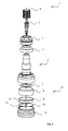
- FIG. 1 This illustrates a first embodiment of a valve device 1 in a schematic view.
- like elements will be described in FIGS FIGS. 1 to 5 with the same reference numerals and similar elements with the same reference numerals with “dash" provided.
- the valve device 1 is in the in the Fig. 1 to 5 11, embodiments illustrated in FIG. 2 essentially comprise two main sections, namely a valve main body 2 and a tire pressure measurement module 27.
- the valve main body 2 is made of, for example, an electrically conductive material such as aluminum and substantially comprises the parts required for a tire valve function: a tire valve 5 with valve cap 6 and a nut 4 with a gasket 3, which serves to attach the valve device to a rim.
- the valve device is pushed from the inside through a valve hole of the rim and the nut 4 with the seal 3 screwed from the outside to the valve device 1.
- the seal 3 can assume a further support function for the valve device 1.
- the valve main body 2 has, for example, a fluid guide, which consists of a central central bore 17 (FIG. Fig. 2 to 5 ) and corresponding side holes 14 is formed.
- a fluid can be filled from the outside into the tire interior or this can be drained from the tire interior.
- the fluorine guide is in fluid communication with the tire valve 5.
- the tire pressure measuring module 27 essentially comprises the electronics required for tire pressure measurement and the electronic components required for wireless transmission, such as, for example, printed circuit board (s), chip (s), control device (s), transmitting and / or receiving components, (printed
- the tire pressure measurement module 27 comprises a receptacle (or module housing) 11 with a cavity 13 in which the antenna disc 10 , the tire pressure measuring device 9 and the battery 8 are arranged.
- the receptacle 11 is designed, for example, cup-shaped and the cavity 13 is dimensioned according to the battery 8 and the tire pressure measuring device 9, so that the receptacle 11 can accommodate these components substantially completely.
- the receptacle 11 has a cylindrical outer wall and has a flat bottom. In other embodiments, the receptacle 11 has a different shape and may, for example, be rectangular, square, oval, polygonal or have any other cross-section.
- the tire pressure measurement module 27 is attached to a valve foot portion 15 of the valve main body 2 in some embodiments (see FIG. Fig. 2 to 5 ).
- a valve foot portion 15 of the valve main body 2 in some embodiments (see FIG. Fig. 2 to 5 ).
- at least one region of the valve foot and a region of the receptacle are adapted to one another, so that they can at least partially intermesh.
- the valve foot area extends so far in the direction of the receptacle 11, that, for example, the Vent Stahlende ends at the height of the upper edge of the battery 8, ie at the transition point between the battery 8 and tire pressure measuring device 9.
- the receptacle 11 which is formed, for example, from an electrically non-conductive material, so that the radiated from the antenna disc 10 electromagnetic waves do not couple into the receptacle 11 and not in the valve base 15 in the area in which the antenna disc 10 is arranged.
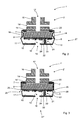
- the valve root portion 15 of the valve main body 2 comprises a cup-shaped portion having cylindrical side walls (see FIG. Fig.2 ).
- the tire pressure measurement module 27 can be inserted with the receptacle 11.
- a corrugated plate 7, which has an opening 20 serves as an electrical contact means between the negative terminal of the battery 8 and a flat area of the valve foot 15, so that an electrical contact between the negative pole and the tire pressure measuring device can be established via the valve foot 15.
- the tire pressure measuring device 9 is configured to measure the fluid pressure, for example air or tire gas pressure, in the tire interior and to transmit measurement data corresponding to the measured tire pressure wirelessly, for example to a central vehicle control.
- the tire pressure measuring device 9 converts, for example, the determined tire pressure data into radio data and transmits the wireless data wirelessly via a transmitting device, for example to a central control of a motor vehicle.
- the electronic components required for this purpose are, for example, on a corresponding motherboard of the tire pressure measuring device 9, as well as in the Fig. 2 to 5 is shown schematically.
- the tire pressure measuring device 9 further has a coupling element 21, which, for example, the transmitting device or its antenna output of the tire pressure measuring device 9 electrically or electromagnetically coupled directly to the antenna disk 10.
- the coupling element 22 has a sleeve 24, in which a spring 23 is arranged.
- the sleeve 24 and the spring 23 support an electrically conductive ball 22 elastically, so that the ball 22 presses against the antenna disk 10 due to the elastic deformation of the spring 23.
- the antenna disk 10 has an opening 12 and is formed from an electrically conductive material.
- the opening 12 points in the direction of the valve main body 2 and is, for example, aligned with its central bore 17.
- the antenna disk 10 is consequently configured such that it can emit electromagnetic waves, which in turn at least partially couple into the valve main body 2.
- the antenna device 10 thus establishes wireless electromagnetic coupling between the tire pressure measuring device 9 and the valve main body 2.
- the valve main body then radiates the received radio waves as a Hertz dipole or cavity radiator, so that it can be received by the central control of the motor vehicle.
- the tire pressure measuring module 27 has, in the first embodiment, a recess 18 which extends annularly around the outer wall of the receptacle 11.
- a recess 18 adhesive which establishes a firm adhesive connection between the inner wall of the cup-like portion of the valve foot 15 and the receptacle 11, so that the tire pressure measuring module 27 is captively connected to the valve foot 15 of the valve main body 2.
- an opening 19 is provided in the middle, which establishes a communicating Fuldthetic to the opening 12 in the antenna disk 10.
- a fluid present in the interior of a tire can penetrate through the openings 19 and 12 in the interior 13 of the tire pressure measurement module 27, so that the tire pressure measuring device 9, the corresponding fluid pressure of the tire is applied and can be measured by her.
- the dimension of the antenna disk 10 is selected so that its diameter is equal to or smaller than the bottom diameter of the receptacle 11, so that the antenna disk 10 rests flush on the bottom portion of the receptacle 11. Consequently, the antenna disk 10 is, for example, clamped between the coupling element 21 and the bottom region of the receptacle 11.
- the antenna disk or other shape eg meander shape, which is also suitable as an antenna, vapor-deposited directly on the bottom portion of the receptacle 11.
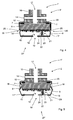
- the in the Fig. 3 and 4 illustrated second embodiment differs substantially from the first embodiment by the manner of attachment of the tire pressure measurement module 27 'to the valve foot 15' of the valve main body 2 '.
- the receptacle 11 'of the tire pressure measurement module 27' has an undercut 26 in the region of the upper edge or the transition region of the battery 8 and the tire pressure measuring device 9, which extends in an annular manner around the cup-shaped receptacle 11 'and projects into the cavity 13' ,
- the cup-shaped portion of the valve foot 15 an elastically deformable portion 25 which can be flanged so that it engages in the undercut 26 of the receptacle 11 '(s. Fig. 4 ).
- the tire pressure measurement module 27 ' can be connected captively to the valve foot 15'.
- the antenna disc 10 substantially forms the bottom of the receptacle 11 '. Accordingly, the opening 19 'in the bottom region of the receptacle 11' forms significantly larger than in the first embodiment.
- the receptacle 11 ' here has a small projection 28 in its bottom area, so that the antenna disk 10 can be held by this projection 28.
Abstract
Description
Die vorliegende Erfindung bezieht sich allgemein auf Ventile und insbesondere auf eine Ventilvorrichtung und ein Reifendruckmessmodul.The present invention relates generally to valves, and more particularly to a valve device and a tire pressure measurement module.
Es ist allgemein bekannt, an ein Ventil eine Reifendruckmesseinheit anzubringen, um den Reifendruck innerhalb eines Fahrzeugreifens zu erfassen. Die Reifendruckmesseinheit kann dabei bspw. den im Fahrzeugreifen erfassten Druck drahtlos an eine zentrale Fahrzeugsteuerung übermitteln.It is well known to attach a tire pressure measuring unit to a valve to detect the tire pressure within a vehicle tire. The tire pressure measuring unit can, for example, transmit the pressure detected in the vehicle tire wirelessly to a central vehicle control system.
So offenbart bspw. das US-Patent
Aufgabe der vorliegenden Erfindung ist es, eine Ventilvorrichtung und ein Reifendruckmessmodul bereitzustellen, das eine zuverlässige, drahtlose Übertragung ermöglicht.The object of the present invention is to provide a valve device and a tire pressure measurement module that enables reliable, wireless transmission.
Nach einem ersten Aspekt stellt die vorliegende Erfindung eine Ventilvorrichtung bereit, mit: einem Ventilhauptkörper, der wenigstens teilweise aus einem elektrisch leitfähigen Material hergestellt ist, einer Reifendruckmesseinrichtung, und einer Antenneneinrichtung, wobei die Reifendruckmesseinrichtung ein elektromagnetisches Koppelelement aufweist, das die Reifendruckmesseinrichtung elektrisch oder elektromagnetisch mit der Antenneneinrichtung koppelt.According to a first aspect, the present invention provides a valve apparatus comprising: a valve main body made at least partially of an electrically conductive material, a tire pressure measuring device, and an antenna device, the tire pressure measuring device including an electromagnetic coupling element that electrically or electromagnetically communicates the tire pressure measuring device the antenna device couples.
Nach einem zweiten Aspekt stellt die vorliegende Erfindung ein Reifendruckmessmodul für eine Ventilvorrichtung nach dem ersten Aspekt der Erfindung bereit, mit: einer Reifendruckmesseinrichtung, einer Antenneneinrichtung, und einem Modulgehäuse, wobei die Reifendruckmesseinrichtung ein Koppelelement aufweist, das die Reifendruckmesseinrichtung mit der Antenneneinrichtung elektrisch oder elektromagnetisch koppelt.In a second aspect, the present invention provides a tire pressure measurement module for a valve device according to the first aspect of the invention, comprising: a tire pressure measurement device, an antenna device, and a module housing; wherein the tire pressure measuring device has a coupling element which electrically or electromagnetically couples the tire pressure measuring device with the antenna device.
Weitere Aspekte und Merkmale der vorliegenden Erfindung ergeben sich aus den abhängigen Ansprüchen, der beigefügten Zeichnung und der nachfolgenden Beschreibung bevorzugter Ausführungsformen.Further aspects and features of the present invention will become apparent from the dependent claims, the accompanying drawings and the following description of preferred embodiments.
Ausführungsformen der Erfindung werden nun beispielhaft und unter Bezugnahme auf die beigefügte Zeichnung beschreiben, in der:
-
Fig. 1 eine erste Ausführungsform einer Ventilvorrichtung in Übereinstimmung mit der vorliegenden Erfindung in einer Explosionsdarstellung veranschaulicht; -
Fig. 2 die Ventilvorrichtung der ersten Ausführungsform in einer Teilquerschnittsansicht zeigt; -
Fig. 3 eine zweite Ausführungsform einer Ventilvorrichtung in Übereinstimmung mit der vorliegenden Erfindung in einer Teilquerschnittsansicht zeigt; -
Fig. 4 die Ventilvorrichtung vonFig. 3 mit gebördeltem Ventilfußrand zur Befestigung einer Reifendruckmesseinrichtung veranschaulicht; und -
Fig. 5 eine dritte Ausführungsform einer Ventilvorrichtung in Übereinstimmung mit der vorliegenden Erfindung in einer Teilquerschnittsansicht zeigt.
-
Fig. 1 illustrates an exploded view of a first embodiment of a valve device in accordance with the present invention; -
Fig. 2 the valve device of the first embodiment in a partial cross-sectional view shows; -
Fig. 3 a second embodiment of a valve device in accordance with the present invention in a partial cross-sectional view shows; -
Fig. 4 the valve device ofFig. 3 illustrated with crimped Ventußußrand for mounting a tire pressure measuring device; and -
Fig. 5 shows a third embodiment of a valve device in accordance with the present invention in a partial cross-sectional view.
In
Wie bereits eingangs ausgeführt, ist es bekannt, dass der von einer Reifendruckmesseinrichtung ermittelte Druck drahtlos bspw. an eine zentrale Fahrzeugsteuerung übermittelt wird.As already explained, it is known that the pressure determined by a tire pressure measuring device is transmitted wirelessly, for example, to a central vehicle control system.
In den Ausführungsformen umfasst eine Ventilvorrichtung typischerweise einen Ventilhauptkörper, der ein Ventil aufnimmt und zusätzlich bspw. eine Reifendruckmesseinrichtung aufnehmen kann. Die Reifendruckmesseinrichtung misst den Luftdruck in dem Fahrzeugreifen und übermittelt den gemessenen Luftdruck drahtlos an einen Empfänger, wie zum Bsp. eine zentrale Fahrzeugsteuerung.In the embodiments, a valve device typically includes a valve main body that receives a valve and may additionally receive, for example, a tire pressure gauge. The tire pressure measuring device measures the air pressure in the vehicle tire and transmits the measured air pressure wirelessly to a receiver, such as a central vehicle control.
Wie auch in der parallelen EP-Anmeldung mit der Anmeldenr. 09000154.6 dieses Anmelders offenbart, deren Beschreibung durch Bezugnahme Bestandteil dieser Patentanmeldung wird, kann bspw. ein Ventilkörper einer Ventilvorrichtung als Antenne dienen. Dazu ist der Antennenhauptkörper bspw. aus einem elektrisch leitfähigen Material wie Metall (z.B. Aluminium) gebildet, sodass der Ventilhauptkörper als eine Art Hertzscher Dipol oder Hohlraumstrahler dienen kann.As in the parallel EP application with the Anmeldungr. No. 09000154.6, the description of which is incorporated herein by way of example, may serve as an antenna for a valve body of a valve device. For this purpose, the antenna main body is formed of, for example, an electrically conductive material such as metal (e.g., aluminum) so that the valve main body can serve as a kind of Hertzian dipole or cavity radiator.
Wenn der Ventilkörper oder Teile des Ventilkörper als Antenne dienen, können die von ihm abgestrahlten elektromagnetischen Welle auf direktem Wege zu dem Empfänger gelangen und müssen nicht den Fahrzeugreifen durchdringen, wie es bspw. der eingangs erwähnte Stand der Technik (
Damit bspw. der Ventilhauptkörper als Antenne dienen kann, müssen die Funksignale von der Reifendruckmesseinrichtung in den Ventilhauptkörper elektrisch oder elektromagnetisch eingekoppelt werden. In der parallelen
Bei den Ausführungsformen der vorliegenden Anmeldung kann der Ventilhauptkörper ebenfalls als Antenne dienen. Allerdings koppelt das Koppelelement die Sendeeinrichtung der Reifendruckmesseinrichtung nicht (nur) direkt elektrisch an den Ventilhauptkörper, sondern es koppelt die Reifendruckmesseinrichtung mit einer Antenneneinrichtung, die dann bspw. elektromagnetische Wellen aussendet, die wiederum in den Ventilhauptkörper einkoppeln. Diese Kopplung kann dabei als direkte elektrische Verbindung zwischen der Reifendruckmesseinrichtung, der Sendeeinrichtung bzw. einem Antennenausgang der Reifendruckmesseinrichtung, oder zum Beispiel auch kontaktlos als elektromagnetische Kopplung zur Antenneneinrichtung ausgebildet sein. Durch die Einkopplung der elektromagnetischen Wellen von der Antenneeinrichtung in den Ventilhauptkörper kann dieser wiederum als Antenne dienen, indem er bspw. in der Art eines Hertzschen Dipols oder Hohlraumstrahlers elektromagnetische Wellen abstrahlt, die bspw. den gemessenen Reifendruck repräsentieren und die dann bspw. von einer zentralen Fahrzeugsteuerung empfangen werden können.In the embodiments of the present application, the valve main body may also serve as an antenna. However, the coupling element does not directly (only) electrically couple the transmitting device of the tire pressure measuring device to the valve main body, but it couples the tire pressure measuring device with an antenna device which then emits electromagnetic waves, for example, which in turn couple into the valve main body. This coupling can be used as a direct electrical connection between the tire pressure measuring device, the transmitting device or an antenna output of the tire pressure measuring device, or for example be formed contactless as electromagnetic coupling to the antenna device. By coupling the electromagnetic waves from the antenna device in the valve main body, this in turn can serve as an antenna by radiating electromagnetic waves, for example, in the manner of a Hertzian dipole or cavity radiator, representing, for example, the measured tire pressure and then, for example. From a central Vehicle control can be received.
Die Antenneneinrichtung ist bei manchen Ausführungsformen scheibenförmig ausgebildet und kann bspw. eine Öffnung aufweisen. Dabei bildet die Antenneneinrichtung bei manchen Ausführungsformen eine Scheibenantenne, die geeignet ist, elektromagnetische Wellen abzustrahlen. Die von der Antenneneinrichtung abgestrahlten elektromagnetischen Wellen koppeln, wie erwähnt, wenigstens teilweise in den Ventilhauptkörper ein, der nicht nur die elektromagnetischen Wellen empfängt, sondern diese selbst wiederum abstrahlt. Die Scheibenantenne ist dabei bspw. derart in der Ventilvorrichtung angeordnet, dass die Öffnung in Richtung des Ventilhauptkörpers zeigt.The antenna device is disc-shaped in some embodiments and may, for example, have an opening. In this case, in some embodiments, the antenna device forms a glass antenna which is suitable for emitting electromagnetic waves. As mentioned, the electromagnetic waves radiated by the antenna device at least partially couple into the valve main body, which not only receives the electromagnetic waves, but in turn radiates them. In this case, the glass antenna is, for example, arranged in the valve device such that the opening points in the direction of the valve main body.
Ist die Antenneneinrichtung bspw. scheibenförmig ausgestaltet, so entsteht bei manchen Ausführungsformen ein Kreisstrom in der scheibenförmigen Antenneneinrichtung, wenn das Koppelelement einen entsprechenden Wechselstrom einkoppelt. Weist die Antenneneinrichtung bspw. eine Öffnung auf, so kann die Antenneneinrichtung ähnlich einem Hohlstrahler fungieren, der geeignet ist, elektromagnetische Strahlung an einem Öffnungsende gerichtet, bspw. in Richtung des Ventilhauptkörpers, abzustrahlen.If, for example, the antenna device is disc-shaped, in some embodiments a circular current is produced in the disk-shaped antenna device when the coupling element couples in a corresponding alternating current. If the antenna device has, for example, an opening, the antenna device can function similarly to a hollow radiator which is suitable for emitting electromagnetic radiation at an opening end, for example in the direction of the valve main body.
Die Antenneneinrichtung hat bei anderen Ausführungsformen eine andere Form, die als Antenne geeignet ist, wie bspw. eine mäanderartige Form, die dann bspw. elektromagnetische Wellen dipolartig abstrahlt.In other embodiments, the antenna device has a different shape that is suitable as an antenna, such as, for example, a meander-like shape, which then radiates dipole-like, for example, electromagnetic waves.
Folglich dient die Antenneneinrichtung bei manchen Ausführungsformen ebenfalls als elektromagnetisches Koppelelement, das die von dem Koppelelement, das zwischen der Sendeeinrichtung und der Antenneneinrichtung angeordnet ist, eingekoppelten Wechselströme in elektromagnetische Wellen umwandelt und diese derart abstrahlt, dass sie der Ventilhauptkörper empfangen und wiederum selbst abstrahlen kann.Thus, in some embodiments, the antenna device also serves as an electromagnetic coupling element that converts the alternating currents injected from the coupling element disposed between the transmitting device and the antenna device into electromagnetic waves and radiates them such that they can be received by the valve main body and in turn radiated by itself.
Dadurch, dass die Antenneneinrichtung als elektromagnetisches Koppelelement bei manchen Ausführungsformen dienen kann, ist es bspw. möglich die Reifendruckmesseinrichtung derart in einem Aufnahmebereich des Ventilhauptkörpers anzuordnen, dass sie wenigstens teilweise zwischen dem Ventilhauptkörper und der Antenneneinrichtung liegt. Dies vereinfacht den Aufbau der gesamten Ventilvorrichtung, da die Reifendruckmesseinrichtung, die bspw. eine Platine aufweist, nicht mit dem Koppelelement und elektronischen Bauteilen, die zur Reifendruckerfassung vorgesehen sind, in Richtung des Ventilhauptkörpers angebracht werden müssen, sondern bspw. auch in die entgegengesetzte Richtung, vom Ventilhauptkörper weg, orientiert angeordnet werden können.Characterized in that the antenna device as an electromagnetic coupling element in In some embodiments, for example, it is possible to arrange the tire pressure measuring device in a receiving area of the valve main body such that it lies at least partially between the valve main body and the antenna device. This simplifies the structure of the entire valve device, since the tire pressure measuring device having, for example, a circuit board, not with the coupling element and electronic components, which are provided for tire pressure detection, must be mounted in the direction of the valve main body, but, for example, in the opposite direction, away from the valve main body, oriented.
Der Ventilhauptkörper weist bei manchen Ausführungsformen bspw. zwei Bereiche auf: Einen Ventilaufnahmebereich, der bspw. rohartig ausgestaltet ist, und dazu dient, das eigentliche Ventil aufzunehmen und einen zweiten Bereich, der sich an den ersten anschließt und den Ventilfuß bildet. Der Ventilfuß kann bspw. zylinderförmig ausgebildet sein und einen Durchmesser aufweisen, der größer als der des rohrförmigen Ventilaufnahmebereiches ist. Der Ventilfuß ist bei manchen Ausführungsbeispielen hohlzylindrisch gebildet und ist bspw. geeignet, die Reifendruckmesseinrichtung wenigstens teilweise aufzunehmen. Dabei weist der Übergang zwischen dem rohrförmigen Aufnahmeabschnitt für das Ventil und dem zylinderförmigen Aufnahmeabschnitt für die Reifendruckmesseinrichtung bspw. einen Bodenbereich auf.For example, in some embodiments, the valve main body has two areas: a valve receiving area, which is, for example, configured as a tube, and serves to receive the actual valve and a second area, which adjoins the first and forms the valve foot. The valve foot may, for example, be cylindrical and have a diameter which is greater than that of the tubular valve receiving area. The valve foot is formed in some embodiments, a hollow cylinder and is, for example, suitable to at least partially receive the tire pressure measuring device. In this case, the transition between the tubular receiving portion for the valve and the cylindrical receiving portion for the tire pressure measuring device, for example, a bottom portion.
Die Anordnung der Reifendruckmesseinrichtung ist dann bspw. zwischen dem Bodenbereich des Ventilhauptkörpers und der, z.B. scheibenförmigen, Antenneneinrichtung angeordnet. Das Koppelelement ist demnach auf der Seite der Reifendruckmesseinrichtung angeordnet, die von dem Ventilhauptkörper abgewendet ist.The arrangement of the tire pressure measuring device is then, for example, between the bottom portion of the valve main body and, e.g. disc-shaped, antenna device arranged. The coupling element is thus arranged on the side of the tire pressure measuring device, which is averted from the valve main body.
Damit ist bei manchen Ausführungsformen keine (direkte) elektrisch leitende Verbindung zwischen dem Ventilkörper und der Antenneneinrichtung vorhanden. Folglich koppelt die Reifendruckmesseinrichtung über die Sendeeinrichtung die Funkdaten, die dem gemessenen Reifendruck entsprechen, über das Koppelelement in die Antenneneinrichtung, die dann wiederum elektromagnetisch an den Ventilhauptkörper koppelt, sodass der Ventilhauptkörper als Antenne dienend die Funkdaten weiter übertragen kann. Auf diese Weise gelangen die Funksignale aus dem Reifeninneren, ohne dass sie bspw. von dem Reifenmantel abgeschwächt werden.Thus, in some embodiments, there is no (direct) electrically conductive connection between the valve body and the antenna device. Consequently, the tire pressure measuring device couples, via the transmitting device, the radio data corresponding to the measured tire pressure via the coupling element into the antenna device, which in turn couples electromagnetically to the valve main body so that the valve main body can continue to transmit the radio data as an antenna. In this way, the radio signals reach the inside of the tire without being weakened, for example, by the tire casing.
Bei manchen Ausführungsformen umfasst die Ventilvorrichtung einen elektrischen Energiespeicher, der zwischen dem Ventilhauptkörper und der Reifendruckmesseinrichtung angeordnet ist. Als elektrische Energiespeicher kommt bspw. eine Batterie oder ein Akkumulator zum Einsatz.In some embodiments, the valve device comprises an electrical Energy storage, which is arranged between the valve main body and the tire pressure measuring device. As an electrical energy storage is, for example, a battery or an accumulator used.
Manche Ausführungsformen umfassen weiter einen leitenden Abschnitt, der zwischen dem Ventilhauptkörper bzw. dessen Boden und dem Energiespeicher angeordnet ist. Der leitende Abschnitt kann dabei als Wellscheibe ausgebildet sein, die bspw. eine Öffnung aufweist. Der leitende Abschnitt ist bei manchen Ausführungsformen integral mit dem Ventilhauptkörper verbunden. Bei manchen Ausführungsformen ist der elektrische Minuspol des Energiespeichers mit dem elektrisch leitenden Abschnitt verbunden ist, sodass darüber ein Kontakt mit Ventilhauptkörper hergestellt wird, der wiederum zur Energieversorgung die Reifendruckmesseinrichtung elektrisch kontaktiert.Some embodiments further include a conductive portion disposed between the valve main body and its bottom and the energy storage. The conductive portion may be formed as a corrugated disk having, for example, an opening. The conductive portion is integrally connected to the valve main body in some embodiments. In some embodiments, the negative electrical pole of the energy store is connected to the electrically conductive portion so that contact is made with the valve main body, which in turn electrically contacts the tire pressure measuring device for supplying energy.
Bei manchen Ausführungsformen umfasst die Ventilvorrichtung weiter eine Aufnahme oder ein Reifendruckmessmodul mit einem Aufnahmebereich, in dem zumindest die Reifendruckmesseinrichtung und bei manchen Ausführungsformen weiter auch die Antenneneinrichtung und/oder der elektrische Energiespeicher angeordnet ist/sind.In some embodiments, the valve device further comprises a receptacle or a tire pressure measurement module with a receiving region in which at least the tire pressure measuring device and in some embodiments also the antenna device and / or the electrical energy store is / are arranged.
Die Aufnahme ist zum Beispiel aus einem spritzgussfähigen Material wie Kunststoff gebildet und so dimensioniert, dass der (zylinderförmige) Abschnitt des Ventilfußes sie wenigstens teilweise aufnehmen kann. Damit bilden bei manchen Ausführungsformen der Aufnahmeabschnitt des Ventilfußes des Ventilhauptkörpers und die Aufnahme für die Reifendruckmesseinrichtung zusammen einen wenigstens teilweise geschlossenen Raum, wenn die beiden Teile miteinander verbunden sind. In diesem Raum ist bei manchen Ausführungsformen wenigstens eines der folgenden Teile angeordnet: elektrisch leitender Abschnitt, Energiespeicher, Reifendruckmesseinrichtung und/oder Antenneneinrichtung.The receptacle is formed, for example, from an injection-moldable material such as plastic and dimensioned so that the (cylindrical) portion of the valve foot can at least partially accommodate them. Thus, in some embodiments, the receiving portion of the valve foot of the valve main body and the receptacle for the tire pressure measuring device together form an at least partially closed space when the two parts are connected together. In some embodiments, at least one of the following parts is arranged in this space: electrically conductive section, energy store, tire pressure measuring device and / or antenna device.
Bei manchen Ausführungsformen bildet die Antenneneinrichtung einen Teil des Bodens der Aufnahme, insbesondere wenn die bspw. scheibenförmig ausgebildet ist. Die Aufnahme ist bei manchen Ausführungsformen becherartig ausgebildet und wird bspw. so an/in dem Ventilfuß angeordnet, dass die offene Seite der Becherform in Richtung des Ventilfußes liegt, während der Boden der Becherform gegenüber des Ventilfußes angeordnet ist.In some embodiments, the antenna device forms a part of the bottom of the receptacle, in particular if, for example, the disc-shaped design. The receptacle is cup-shaped in some embodiments and is arranged, for example, on / in the valve foot, that the open side of the cup shape is in the direction of the valve foot, while the bottom of the cup shape is arranged opposite the valve foot.
Folglich ist bei manchen Ausführungsformen die Reihenfolge der in dem aus Ventilfuß und Aufnahme gebildeten Raum von Ventilfuß wegblickend, d.h. in Richtung des Reifeninneren, angeordneten Teile wie folgt: elektrisch leitender Abschnitt, Energiespeicher, Reifendruckmesseinrichtung, Antenneneinrichtung und - je nach Ausführungsformen - Bodenplatte oder Teilbodenabschnitt der Aufnahme.Thus, in some embodiments, the order of the valve foot is in that order and receiving space away from the valve foot looking away, ie in the direction of the tire interior, arranged parts as follows: electrically conductive section, energy storage, tire pressure measuring device, antenna device and - depending on embodiments - bottom plate or partial bottom portion of the recording.
Die Antenneneinrichtung ist bei manchen Ausführungsformen als selbstständiges Bauelement, bspw. als Metallscheibe ausgebildet. Bei anderen Ausführungsformen wird diese bspw. durch Aufdampfen bspw. auf den Bodenabschnitt der Aufnahme ausgebildet.In some embodiments, the antenna device is designed as an independent component, for example as a metal disk. In other embodiments, this is, for example, by vapor deposition, for example, formed on the bottom portion of the receptacle.
Bei manchen Ausführungsformen weist sowohl die Antenneneinrichtung als auch der Boden der becherförmigen oder anders geformten Aufnahme, eine Öffnung auf, durch die Fluid, wie bspw. Luft oder Reifengas, aus dem Reifeninneren in die Ventilvorrichtung eindringen kann. Dadurch liegt der Fluiddruck, der sich im inneren des Reifens ausbildet ebenfalls an der druckempfindlichen Messeinrichtung der Reifendruckmesseinrichtung an. Damit ist es bei manchen Ausführungsformen nicht erforderlich, zusätzliche Öffnungen bspw. in einer Seitenwand der Aufnahme vorzusehen.In some embodiments, both the antenna device and the bottom of the cup-shaped or other shaped receptacle have an opening through which fluid, such as air or tire gas, may enter the valve device from within the tire. As a result, the fluid pressure that forms in the interior of the tire is also applied to the pressure-sensitive measuring device of the tire pressure measuring device. Thus, in some embodiments, it is not necessary to provide additional openings, for example, in a side wall of the receptacle.
Dadurch, dass bei manchen Ausführungsformen die Aufnahme aus einem nicht oder nur schlecht leitenden Material gebildet ist und in dieser Aufnahme bspw. die Antenneneinrichtung, die Reifendruckmesseinrichtung und der Energiespeicher angeordnet sind, ist zumindest die Antenneneinrichtung von dem Ventilhauptkörper elektrisch isoliert, wenn die Aufnahme innerhalb des Ventilfußes angeordnet ist, da sich dann bspw. eine Wand der Aufnahme zwischen der Antenneneinrichtung und der (elektrisch leitenden) Wand des Ventilfußes befindet. Wie oben beschrieben, koppelt die Antenneneinrichtung dann elektromagnetisch mit dem Ventilhauptkörper.Due to the fact that, in some embodiments, the receptacle is formed from a material that is poorly or not conductively conductive, and in this receptacle, for example, the antenna device, the tire pressure measuring device and the energy accumulator are arranged, at least the antenna device is electrically insulated from the valve main body when the receptacle is inside the receptacle Valve base is arranged, since then, for example, a wall of the receptacle between the antenna device and the (electrically conductive) wall of the valve foot is. As described above, the antenna device then electromagnetically couples with the valve main body.
Bei manchen Ausführungsformen ist die Aufnahme modulartig mit dem Ventilhauptkörper, bspw. mit seinem Ventilfuß, verbindbar. Dabei bildet bspw. die Aufnahme, die in ihr angeordnete Reifendruckmesseinrichtung und Antenneneinrichtung ein gemeinsames Reifendruckmessmodul, das mit dem Ventilhauptkörper verbindbar ist.In some embodiments, the receptacle is modularly connected to the valve main body, eg. With its valve foot, connectable. In this case, for example, the receptacle, the tire pressure measuring device and antenna device arranged in it form a common tire pressure measuring module that can be connected to the valve main body.
Bei manchen Ausführungsformen weist die Aufnahme eine Hinterschneidung auf und der Ventilfuß des Ventilhauptkörpers weist einen elastisch verformbaren Bereich auf, der durch Verformung, wie bspw. Umbördeln, in die Hinterschneidung eingreifen kann und somit die Aufnahme fest mit dem Ventilhauptkörper verbindet. Bei anderen Ausführungsformen weist die Aufnahme bspw. (zusätzlich) ein Außengewinde und der Ventilfuß ein Innengewinde auf, sodass die Aufnahme in den Ventilfuß geschraubt werden kann. Es kann auch (zusätzlich) die Aufnahme in den Ventilfuß geklebt oder eingeclipst werden. Dafür kann die Aufnahme eine entsprechend Aussparung aufweisen, in der bspw. Klebstoff eingebracht werden kann bzw. in die ein entsprechender Vorsprung des Ventilfußes einrastet.In some embodiments, the receptacle has an undercut and the valve foot of the valve main body has an elastically deformable portion which can engage by deformation, such as. Flanging, in the undercut and thus firmly connects the receptacle with the valve main body. In other embodiments has the inclusion, for example. (In addition) an external thread and the valve foot on an internal thread, so that the receptacle can be screwed into the valve foot. It can also (additionally) glued or clipped the receptacle in the valve foot. For this, the receptacle can have a corresponding recess in which, for example, adhesive can be introduced or into which a corresponding projection of the valve foot engages.
Bei manchen Ausführungsformen endet der elektrisch leitende Ventilfußbereich vor der Antenneneinrichtung. Die Aufnahme bzw. das Modulgehäuse sind bspw. aus elektrisch nicht leitfähigem Material gebildet, sodass in dem Bereich der Antenneneinrichtung kein elektrisch leitendes Material vorhanden ist und elektromagnetische Wellen in diesem Bereich aus der Ventilvorrichtung ausgestrahlt werden können.In some embodiments, the electrically conductive valve footing terminates in front of the antenna device. The receptacle or the module housing are formed, for example, from electrically nonconductive material, so that in the region of the antenna device no electrically conductive material is present and electromagnetic waves in this area can be emitted from the valve device.
Manche Ausführungsformen betreffen ein Reifendruckmessmodul für eine Ventilvorrichtung. Das Reifendruckmessmodul umfasst bspw. eine Reifendruckmesseinrichtung, eine Antenneneinrichtung und ein Modulgehäuse, das bspw. im Wesentlichen der oben erwähnten Aufnahme entspricht. Die Reifendruckmesseinrichtung weist ein Koppelelement auf, das eine Sendeeinrichtung der Reifendruckmesseinrichtung mit der Antenneneinrichtung elektromagnetisch und/oder elektrisch koppelt. Die obigen Ausführungen zu den einzelnen Bestandteilen Aufnahme, Antenneneinrichtung, Reifendruckmesseinrichtung und elektrisch leitender Abschnitt gelten dementsprechend auch für die Ausführungsformen, die das Reifendruckmessmodul betreffen.Some embodiments relate to a tire pressure measurement module for a valve device. The tire pressure measurement module includes, for example, a tire pressure measuring device, an antenna device and a module housing, which, for example, substantially corresponds to the above-mentioned receptacle. The tire pressure measuring device has a coupling element which electromagnetically and / or electrically couples a transmitting device of the tire pressure measuring device with the antenna device. The above statements on the individual components receiving, antenna device, tire pressure measuring device and electrically conductive section also apply accordingly to the embodiments relating to the tire pressure measurement module.
Zurückkommend zu
Die Ventilvorrichtung 1 setzt sich bei den in den
Der Ventilhauptkörper 2 ist bspw. aus einem elektrisch leitfähigen Material wie Aluminium hergestellt und umfasst im Wesentlichen die für eine Reifenventilfunktion benötigten Teile: ein Reifenventil 5 mit Ventilkappe 6 und eine Mutter 4 mit einer Dichtung 3, die zur Befestigung der Ventilvorrichtung an einer Felge dient. Dabei wird die Ventilvorrichtung von innen durch ein Ventilloch der Felge geschoben und die Mutter 4 mit der Dichtung 3 von außen an der Ventilvorrichtung 1 festgeschraubt. Dadurch ist die Ventilvorrichtung sicher in der Felge gehalten und die Dichtung 3 sorgt für eine gute Abdichtung, sodass das Fluid, wie Luft oder Reifengas, im Inneren des Reifens verbleibt. Zusätzlich kann die Dichtung 3 bei manchen Ausführungsformen eine weitere Stützfunktion für die Ventilvorrichtung 1 übernehmen.The valve
Der Ventilhauptkörper 2 weist bspw. eine Fluidführung auf, die aus einer zentralen Mittenbohrung 17 (
Das Reifendruckmessmodul 27 umfasst im Wesentlichen die für die Reifendruckmessung benötigte Elektronik und die für die drahtlose Übertragung erforderlichen elektronischen Bauteile, wie bspw. Leiterplatte(n), Chip(s), Steuereinrichtung(en), Sende- und/oder Empfangskomponenten, (Druck-)-Sensor(en) usw. Dazu umfasst das Reifendruckmessmodul 27 eine Reifendruckmesseinrichtung 9, einen als Batterie ausgestalteten Energiespeicher 8 und eine Antennenscheibe 10. Außerdem umfasst das Reifendruckmessmodul 27 eine Aufnahme (oder Modulgehäuse) 11 mit einem Hohlraum 13, in der die Antennenscheibe 10, die Reifendruckmesseinrichtung 9 und die Batterie 8 angeordnet sind.The tire
Die Aufnahme 11 ist bspw. becherförmig ausgestaltet und der Hohlraum 13 ist entsprechend der Batterie 8 und der Reifendruckmesseinrichtung 9 dimensioniert, sodass die Aufnahme 11 diese Bauteile im Wesentlichen vollständig aufnehmen kann. Die Aufnahme 11 hat eine zylindrische Außenwand und weist einen planen Boden auf. Bei anderen Ausführungsformen weist die Aufnahme 11 eine andere Form auf und kann bspw. rechteckig, quadratisch, oval, mehreckig sein oder einen beliebigen anderen Querschnitt aufweisen.The
Das Reifendruckmessmodul 27 wird bei manchen Ausführungsformen an einen Ventilfußbereich 15 des Ventilhauptkörpers 2 angebracht (s.
So umfasst bei der ersten Ausführungsform der Ventilfußbereich 15 des Ventilhauptkörpers 2 einen becherförmigen Bereich mit zylindrischen Seitenwänden (s.
Die Reifendruckmesseinrichtung 9 ist ausgestaltet, den Fluiddruck, bspw. Luft- oder Reifengasdruck, im Reifeninneren zu messen und dem gemessenen Reifendruck entsprechende Messdaten drahtlos, bspw. an eine zentrale Fahrzeugsteuerung, zu übermitteln. Dazu wandelt die Reifendruckmesseinrichtung 9 bspw. die ermittelten Reifendruckdaten in Funkdaten um und übermittelt die Funkdaten drahtlos über eine Sendeeinrichtung bspw. an eine zentrale Steuerung eines Kraftfahrzeugs. Die dafür benötigten elektronischen Komponenten befinden sich bspw. auf einer entsprechenden Hauptplatine der Reifendruckmesseinrichtung 9, wie auch in den
Die Reifendruckmesseinrichtung 9 weist weiter ein Koppelelement 21 auf, das bspw. die Sendeeinrichtung bzw. deren Antennenausgang der Reifendruckmesseinrichtung 9 elektrisch bzw. elektromagnetisch direkt mit der Antennenscheibe 10 koppelt. Das Koppelement 22 weist eine Hülse 24 auf, in der eine Feder 23 angeordnet ist. Die Hülse 24 und die Feder 23 lagern eine elektrisch leitende Kugel 22 elastisch, sodass die Kugel 22 aufgrund der elastischen Verformung der Feder 23 gegen die Antennenscheibe 10 drückt. Bei alternativen Ausführungsformen weist das Koppelelement 21 bspw. einen Stift anstelle der Kugel 22 oder bspw. eine Feder mit einer Kontaktfläche auf, um den elektrischen Kontakt zur Antennenscheibe 10 herzustellen.The tire
Folglich gelangen die von der Reifendruckmesseinrichtung 9 über die Sendeeinrichtung bzw. einen Antennenausgang übermittelten Funkdaten in die Antennenscheibe 10. Die Antennenscheibe 10 weist eine Öffnung 12 auf und ist aus einem elektrisch leitenden Material gebildet. Die Öffnung 12 zeigt dabei in Richtung des Ventilhauptkörpers 2 und ist bspw. mit seiner Mittenbohrung 17 ausgerichtet. Die Antennenscheibe 10 ist folglich derart ausgestaltet, dass sie elektromagnetische Wellen aussenden kann, die wiederum wenigstens teilweise in den Ventilhauptkörper 2 einkoppeln. Folglich stellt die Antenneneinrichtung 10 auf diese Weise eine drahtlose elektromagnetische Kopplung zwischen der Reifendruckmesseinrichtung 9 und dem Ventilhauptkörper 2 her. Der Ventilhauptkörper strahlt dann die empfangenen Funkwellen als Hertzscher Dipol oder Hohlraumstrahler ab, sodass sei von der zentralen Steuerung des Kraftfahrzeugs empfangen werden können.Consequently, the radio data transmitted by the tire
Das Reifendruckmessmodul 27 weist bei der ersten Ausführungsform eine Vertiefung 18 auf, die sich ringförmig um die Außenwand der Aufnahme 11 erstreckt. Beim Zusammenbau der Ventilvorrichtung kann in diese Vertiefung 18 Klebstoff eingebracht werden, der eine feste Klebeverbindung zwischen der Innenwand des becherartigen Abschnitts des Ventilfußes 15 und der Aufnahme 11 herstellt, sodass das Reifendruckmessmodul 27 unverlierbar mit dem Ventilfuß 15 des Ventilhauptkörpers 2 verbunden ist.The tire
In einem Bodenbereich der Aufnahme 11 ist in der Mitte eine Öffnung 19 vorgesehen, die eine kommunizierende Fuldverbindung zu der Öffnung 12 in der Antennenscheibe 10 herstellt. Folglich kann ein Fluid, das im Inneren eines Reifens vorhanden ist, durch die Öffnungen 19 und 12 in den Innenraum 13 des Reifendruckmessmoduls 27 eindringen, sodass an der Reifendruckmesseinrichtung 9 der entsprechende Fluiddruck des Reifens anliegt und von ihr gemessen werden kann.In a bottom region of the
Bei der ersten Ausführungsform ist die Dimension der Antennenscheibe 10 so gewählt, dass ihr Durchmesser gleich oder kleiner dem Bodendurchmesser der Aufnahme 11 ist, sodass die Antennenscheibe 10 bündig auf dem Bodenbereich der Aufnahme 11 aufliegt. Folglich ist die Antennenscheibe 10 bspw. zwischen dem Koppelelement 21 und dem Bodenbereich der Aufnahme 11 eingeklemmt. Bei alternativen Ausführungsformen ist die Antennenscheibe oder eine andere Form, z.B. Mäanderform, die ebenfalls als Antenne geeignet ist, direkt auf dem Bodenbereich der Aufnahme 11 aufgedampft.In the first embodiment, the dimension of the
Die in den
Die in
Auch bei dieser Ausführungsform sind keine weiteren Halterungen vorgesehen, die die Reifendruckeinrichtung, die Batterie und/oder die Antennenscheibe gesondert halten. Folglich ist es bei den Ausführungsformen möglich, das Reifendruckmessmodul einfach herzustellen, indem die einzelnen Komponenten, wie Antennenscheibe, Reifendruckmesseinrichtung und Batterie in dem entsprechend vorgesehenen Hohlraum des Reifendruckmessmoduls angeordnet werden. Dieses so gebildete Reifendruckmessmodul muss dann nur noch mit einem entsprechenden Aufnahmebereich des Ventilhauptkörpers verbunden werden, um die Ventilvorrichtung herzustellen.Also in this embodiment, no further brackets are provided which hold the tire pressure device, the battery and / or the antenna disc separately. Thus, in the embodiments, it is possible to easily manufacture the tire pressure measurement module by disposing the individual components, such as the antenna disk, the tire pressure measurement device and the battery, in the correspondingly provided cavity of the tire pressure measurement module. This tire pressure measuring module thus formed must then only be connected to a corresponding receiving area of the valve main body in order to produce the valve device.
Claims (15)
Priority Applications (2)
| Application Number | Priority Date | Filing Date | Title |
|---|---|---|---|
| EP09010677A EP2206614A1 (en) | 2009-01-08 | 2009-08-19 | Valve device, vehicle tyre pressure measuring unit and vehicle tyre pressure system |
| PCT/EP2009/009332 WO2010078955A1 (en) | 2009-01-08 | 2009-12-30 | Valve device and tyre pressure measuring module |
Applications Claiming Priority (2)
| Application Number | Priority Date | Filing Date | Title |
|---|---|---|---|
| EP09000154.6A EP2208623B1 (en) | 2009-01-08 | 2009-01-08 | Valve device, vehicle tyre pressure measuring unit and vehicle tyre pressure system |
| EP09010677A EP2206614A1 (en) | 2009-01-08 | 2009-08-19 | Valve device, vehicle tyre pressure measuring unit and vehicle tyre pressure system |
Publications (1)
| Publication Number | Publication Date |
|---|---|
| EP2206614A1 true EP2206614A1 (en) | 2010-07-14 |
Family
ID=40551514
Family Applications (2)
| Application Number | Title | Priority Date | Filing Date |
|---|---|---|---|
| EP09000154.6A Not-in-force EP2208623B1 (en) | 2009-01-08 | 2009-01-08 | Valve device, vehicle tyre pressure measuring unit and vehicle tyre pressure system |
| EP09010677A Withdrawn EP2206614A1 (en) | 2009-01-08 | 2009-08-19 | Valve device, vehicle tyre pressure measuring unit and vehicle tyre pressure system |
Family Applications Before (1)
| Application Number | Title | Priority Date | Filing Date |
|---|---|---|---|
| EP09000154.6A Not-in-force EP2208623B1 (en) | 2009-01-08 | 2009-01-08 | Valve device, vehicle tyre pressure measuring unit and vehicle tyre pressure system |
Country Status (2)
| Country | Link |
|---|---|
| EP (2) | EP2208623B1 (en) |
| WO (2) | WO2010078956A1 (en) |
Cited By (3)
| Publication number | Priority date | Publication date | Assignee | Title |
|---|---|---|---|---|
| WO2020160997A1 (en) * | 2019-02-08 | 2020-08-13 | Kemlair | System for measuring at least one physical characteristic for a tyre assembly |
| DE102019214498A1 (en) * | 2019-09-23 | 2021-03-25 | Continental Automotive Gmbh | Wheel valve |
| DE102020209769A1 (en) | 2020-08-04 | 2022-02-10 | Robert Bosch Gesellschaft mit beschränkter Haftung | Sensor and method of making a sensor |
Families Citing this family (1)
| Publication number | Priority date | Publication date | Assignee | Title |
|---|---|---|---|---|
| US8773068B2 (en) | 2011-01-20 | 2014-07-08 | Valence Technology, Inc. | Rechargeable battery systems and rechargeable battery system operational methods |
Citations (4)
| Publication number | Priority date | Publication date | Assignee | Title |
|---|---|---|---|---|
| US4734674A (en) | 1985-04-08 | 1988-03-29 | Jack Taylor | Tire pressure warning system |
| US6799455B1 (en) | 2001-08-09 | 2004-10-05 | Edward F. Neefeldt | Vehicle tire air monitor |
| WO2008031552A1 (en) | 2006-09-11 | 2008-03-20 | Global Dynamix Ag | Motor vehicle tire pressure measuring device |
| US20080121031A1 (en) | 2006-11-28 | 2008-05-29 | Mobiletron Electronics Co., Ltd. | Pressure sensing apparatus for tire |
Family Cites Families (11)
| Publication number | Priority date | Publication date | Assignee | Title |
|---|---|---|---|---|
| US4254312A (en) | 1978-12-29 | 1981-03-03 | Eaton Corporation | Temperature compensated fill valve/pressure switch |
| DE2923258A1 (en) | 1979-06-08 | 1980-12-18 | Moto Meter Ag | ELECTRICAL CONTACT DEVICE FOR MONITORING PRESSURE IN THE TIRE OF A MOTOR VEHICLE WHEEL |
| DE3841995C1 (en) | 1988-12-14 | 1990-06-13 | Moto Meter Ag, 7250 Leonberg, De | Pressure switch for monitoring the pressure in the tyre of a motor vehicle wheel |
| DE4303591C2 (en) * | 1993-02-08 | 1996-02-22 | Alpha Beta Electronics Ag | Valve cap with a device for generating a pressure indication signal for a vehicle tire equipped with a valve |
| US5731516A (en) | 1995-06-07 | 1998-03-24 | Handfield; Michael | System and method for monitoring a pneumatic tire |
| GB9608771D0 (en) | 1996-04-27 | 1996-07-03 | Agrevo Uk Ltd | Pyrimethanil salts |
| TWI257903B (en) | 2005-08-31 | 2006-07-11 | Teng-Wen Huang | Tire pressure detector |
| US7336162B2 (en) * | 2005-12-21 | 2008-02-26 | Lear Corporation | Double mold shot pull to seat universal TPMS sensor |
| FR2909589B1 (en) * | 2006-12-06 | 2011-04-29 | Mobiletron Electronics Co Ltd | PRESSURE DETECTION DEVICE FOR TIRES |
| US7669466B2 (en) * | 2007-05-09 | 2010-03-02 | Lv Sensors, Inc. | Monitoring device attachment to rubber valve stems |
| DE202008009412U1 (en) * | 2008-07-12 | 2008-09-18 | Atrium Enterprises Gmbh | Device for screwing onto a valve, in particular a tire valve or the like. |
-
2009
- 2009-01-08 EP EP09000154.6A patent/EP2208623B1/en not_active Not-in-force
- 2009-08-19 EP EP09010677A patent/EP2206614A1/en not_active Withdrawn
- 2009-12-30 WO PCT/EP2009/009333 patent/WO2010078956A1/en active Application Filing
- 2009-12-30 WO PCT/EP2009/009332 patent/WO2010078955A1/en active Application Filing
Patent Citations (4)
| Publication number | Priority date | Publication date | Assignee | Title |
|---|---|---|---|---|
| US4734674A (en) | 1985-04-08 | 1988-03-29 | Jack Taylor | Tire pressure warning system |
| US6799455B1 (en) | 2001-08-09 | 2004-10-05 | Edward F. Neefeldt | Vehicle tire air monitor |
| WO2008031552A1 (en) | 2006-09-11 | 2008-03-20 | Global Dynamix Ag | Motor vehicle tire pressure measuring device |
| US20080121031A1 (en) | 2006-11-28 | 2008-05-29 | Mobiletron Electronics Co., Ltd. | Pressure sensing apparatus for tire |
Cited By (5)
| Publication number | Priority date | Publication date | Assignee | Title |
|---|---|---|---|---|
| WO2020160997A1 (en) * | 2019-02-08 | 2020-08-13 | Kemlair | System for measuring at least one physical characteristic for a tyre assembly |
| FR3092521A1 (en) * | 2019-02-08 | 2020-08-14 | Kemlair | System for measuring at least one physical characteristic for a pneumatic assembly |
| US11305594B2 (en) | 2019-02-08 | 2022-04-19 | Kemlair | System for measuring at least one physical characteristic for a tyre assembly |
| DE102019214498A1 (en) * | 2019-09-23 | 2021-03-25 | Continental Automotive Gmbh | Wheel valve |
| DE102020209769A1 (en) | 2020-08-04 | 2022-02-10 | Robert Bosch Gesellschaft mit beschränkter Haftung | Sensor and method of making a sensor |
Also Published As
| Publication number | Publication date |
|---|---|
| EP2208623B1 (en) | 2014-11-19 |
| WO2010078956A1 (en) | 2010-07-15 |
| EP2208623A1 (en) | 2010-07-21 |
| WO2010078955A1 (en) | 2010-07-15 |
Similar Documents
| Publication | Publication Date | Title |
|---|---|---|
| EP0417712B1 (en) | Valve for vehicle tyres provided with signalisation means | |
| DE10148876B4 (en) | Device for measuring a tire pressure | |
| EP2206614A1 (en) | Valve device, vehicle tyre pressure measuring unit and vehicle tyre pressure system | |
| DE4411709A1 (en) | Tyre pressure indicator device | |
| EP0924792B1 (en) | Antenna device for a radar level gauge | |
| DE102011013667A1 (en) | On-board information system with antenna for receiving satellite-based geoposition data | |
| WO2008122457A1 (en) | Connector unit for a pressure sensor | |
| EP2466552B1 (en) | On-board information system with mobile radio antenna | |
| EP3276745B1 (en) | Broadband omnidirectional antenna, especially for railway vehicles, and such a rail vehicle | |
| DE102013220091A1 (en) | pressure sensor | |
| DE102006042565A1 (en) | Vehicle tire pressure measurement unit | |
| DE60223015T2 (en) | TIRE PRESSURE MONITORING DEVICES | |
| EP2134578A1 (en) | Connector unit for a pressure measurement cell | |
| DE3605661A1 (en) | ALARM DEVICE | |
| DE102007007939A1 (en) | Antenna arrangement for use on glass roof of vehicle, has antenna fastened to metallic frame of glass floor by recess in glass surface in such manner that metallic frame forms antenna mass, where frame is provided below glass surface | |
| EP1925924B1 (en) | Low cost heat cost allocator | |
| DE102006037695A1 (en) | Hydroaggreagat a vehicle brake system with a sealing element | |
| EP3150035B1 (en) | Electric device with a modular design | |
| DE112018006838B4 (en) | MULTIFUNCTIONAL ENVIRONMENTAL SENSOR DEVICE | |
| DE102009014242A1 (en) | Portable electronic device i.e. personal navigation device, for e.g. car driver, has antenna to transmit and/or receive high-frequency signals that are supplied to and converted in impedance converter, and transmitted to downstream device | |
| DE102013022049A1 (en) | ultrasonic sensor | |
| EP3026005B1 (en) | System of a transponder reader module for fork shoe and fork shoe | |
| DE102012006360A1 (en) | Antenna module for passenger car, has base plate and cover made of dielectric material, and metallic support arranged between board and plate, where circuit components of emitters for broadcast frequencies are arranged on board if necessary | |
| DE202008009016U1 (en) | Device for fixing an RFID chip to rotating metal parts with mehrkeuliger alignment | |
| DE10127862B4 (en) | Coaxial 7/16 coupler with square flange |
Legal Events
| Date | Code | Title | Description |
|---|---|---|---|
| PUAI | Public reference made under article 153(3) epc to a published international application that has entered the european phase |
Free format text: ORIGINAL CODE: 0009012 |
|
| AK | Designated contracting states |
Kind code of ref document: A1 Designated state(s): AT BE BG CH CY CZ DE DK EE ES FI FR GB GR HR HU IE IS IT LI LT LU LV MC MK MT NL NO PL PT RO SE SI SK SM TR |
|
| AX | Request for extension of the european patent |
Extension state: AL BA RS |
|
| 17P | Request for examination filed |
Effective date: 20110113 |
|
| 17Q | First examination report despatched |
Effective date: 20110208 |
|
| GRAP | Despatch of communication of intention to grant a patent |
Free format text: ORIGINAL CODE: EPIDOSNIGR1 |
|
| INTG | Intention to grant announced |
Effective date: 20150206 |
|
| STAA | Information on the status of an ep patent application or granted ep patent |
Free format text: STATUS: THE APPLICATION IS DEEMED TO BE WITHDRAWN |
|
| 18D | Application deemed to be withdrawn |
Effective date: 20150617 |