EP2206456A2 - Shower base assembly - Google Patents
Shower base assembly Download PDFInfo
- Publication number
- EP2206456A2 EP2206456A2 EP10150233A EP10150233A EP2206456A2 EP 2206456 A2 EP2206456 A2 EP 2206456A2 EP 10150233 A EP10150233 A EP 10150233A EP 10150233 A EP10150233 A EP 10150233A EP 2206456 A2 EP2206456 A2 EP 2206456A2
- Authority
- EP
- European Patent Office
- Prior art keywords
- drain
- shower
- honeycomb structure
- base assembly
- shower base
- Prior art date
- Legal status (The legal status is an assumption and is not a legal conclusion. Google has not performed a legal analysis and makes no representation as to the accuracy of the status listed.)
- Withdrawn
Links
- 239000012528 membrane Substances 0.000 claims abstract description 53
- 229920001169 thermoplastic Polymers 0.000 claims abstract description 23
- 239000004416 thermosoftening plastic Substances 0.000 claims abstract description 23
- 239000004744 fabric Substances 0.000 claims abstract description 11
- 239000004575 stone Substances 0.000 claims description 11
- 239000000463 material Substances 0.000 claims description 10
- 238000010276 construction Methods 0.000 claims description 9
- 239000011440 grout Substances 0.000 claims description 9
- 238000000034 method Methods 0.000 claims description 6
- 229920002994 synthetic fiber Polymers 0.000 claims description 5
- XLYOFNOQVPJJNP-UHFFFAOYSA-N water Substances O XLYOFNOQVPJJNP-UHFFFAOYSA-N 0.000 claims description 5
- 238000002347 injection Methods 0.000 claims description 3
- 239000007924 injection Substances 0.000 claims description 3
- 230000013011 mating Effects 0.000 claims description 3
- 239000007787 solid Substances 0.000 claims description 2
- 239000004033 plastic Substances 0.000 claims 1
- 238000009434 installation Methods 0.000 abstract description 23
- 229920000728 polyester Polymers 0.000 abstract description 5
- 238000004078 waterproofing Methods 0.000 description 4
- 229920000122 acrylonitrile butadiene styrene Polymers 0.000 description 3
- 230000008901 benefit Effects 0.000 description 3
- 230000005540 biological transmission Effects 0.000 description 3
- 239000004570 mortar (masonry) Substances 0.000 description 3
- RYGMFSIKBFXOCR-UHFFFAOYSA-N Copper Chemical compound [Cu] RYGMFSIKBFXOCR-UHFFFAOYSA-N 0.000 description 2
- 238000009435 building construction Methods 0.000 description 2
- 239000000919 ceramic Substances 0.000 description 2
- 229910052802 copper Inorganic materials 0.000 description 2
- 239000010949 copper Substances 0.000 description 2
- 239000002184 metal Substances 0.000 description 2
- 229910052751 metal Inorganic materials 0.000 description 2
- 239000000203 mixture Substances 0.000 description 2
- 239000004576 sand Substances 0.000 description 2
- 229910001018 Cast iron Inorganic materials 0.000 description 1
- 239000011398 Portland cement Substances 0.000 description 1
- 239000000853 adhesive Substances 0.000 description 1
- 230000001070 adhesive effect Effects 0.000 description 1
- 229910045601 alloy Inorganic materials 0.000 description 1
- 239000000956 alloy Substances 0.000 description 1
- 230000004888 barrier function Effects 0.000 description 1
- 239000007767 bonding agent Substances 0.000 description 1
- 239000000969 carrier Substances 0.000 description 1
- 230000006835 compression Effects 0.000 description 1
- 238000007906 compression Methods 0.000 description 1
- 238000005336 cracking Methods 0.000 description 1
- 230000000994 depressogenic effect Effects 0.000 description 1
- 230000000694 effects Effects 0.000 description 1
- 239000000945 filler Substances 0.000 description 1
- 238000009408 flooring Methods 0.000 description 1
- 239000006260 foam Substances 0.000 description 1
- 238000007654 immersion Methods 0.000 description 1
- 239000007788 liquid Substances 0.000 description 1
- 238000012986 modification Methods 0.000 description 1
- 230000004048 modification Effects 0.000 description 1
- 238000009428 plumbing Methods 0.000 description 1
- 229920006327 polystyrene foam Polymers 0.000 description 1
- 238000002360 preparation method Methods 0.000 description 1
- 238000007655 standard test method Methods 0.000 description 1
- 238000012360 testing method Methods 0.000 description 1
Images


Classifications
-
- A—HUMAN NECESSITIES
- A47—FURNITURE; DOMESTIC ARTICLES OR APPLIANCES; COFFEE MILLS; SPICE MILLS; SUCTION CLEANERS IN GENERAL
- A47K—SANITARY EQUIPMENT NOT OTHERWISE PROVIDED FOR; TOILET ACCESSORIES
- A47K3/00—Baths; Douches; Appurtenances therefor
- A47K3/28—Showers or bathing douches
- A47K3/40—Pans or trays
- A47K3/405—Pans or trays flush with the surrounding floor, e.g. for easy access
-
- Y—GENERAL TAGGING OF NEW TECHNOLOGICAL DEVELOPMENTS; GENERAL TAGGING OF CROSS-SECTIONAL TECHNOLOGIES SPANNING OVER SEVERAL SECTIONS OF THE IPC; TECHNICAL SUBJECTS COVERED BY FORMER USPC CROSS-REFERENCE ART COLLECTIONS [XRACs] AND DIGESTS
- Y10—TECHNICAL SUBJECTS COVERED BY FORMER USPC
- Y10T—TECHNICAL SUBJECTS COVERED BY FORMER US CLASSIFICATION
- Y10T29/00—Metal working
- Y10T29/49—Method of mechanical manufacture
- Y10T29/4998—Combined manufacture including applying or shaping of fluent material
Definitions
- the present invention relates to a prefabricated shower base assembly for tile and stone applications in showers.
- Tile and stone covered showers have been used for many years; however, construction methods for constructing showers and wet areas have changed dramatically such that construction of a sub-base is necessary to provide support for tile or stone floor surfaces. For example, waterproofing beneath the tile or stone is particularly necessary in multi-story constructions with living space beneath the shower area. This led to the creation/use of waterproof envelopes/barriers under the tile or stone, known as "shower pans.”
- Early shower pans were constructed of copper, sheet metal or sheet lead, and were clamped to the drain typically with a clamping flange. These pans were then filled with a Portland cement and sand mixture, so that, when cured, they provided a base that was acceptable for bonding tile and stone.
- these types of shower pans were/are difficult and time-consuming to construct, and they were/are prone to leaking.
- the most common drain that is used in shower and wet area installations is the "clamping ring drain.” They are typically manufactured in cast iron, PVC and ABS materials and are available from a vast number of distributors and outlets. Depending on local building codes, installation of the drain most often falls under the plumbing code. However, the responsibility for the waterproof integrity and flood testing of the installation most often lies on the plumber. This requires coordination of skilled trades, which can lead to inefficiencies and hence higher costs during installation.
- pre-manufactured shower bases and trays often still require repeated trips back to the installation site by skilled trades, thus still resulting in greater installation costs than desired.
- grout and tile are relatively brittle and very sensitive to any deflection, which leads to cracking when the floor flexes or is stressed, which in turn leads to water leak problems.
- rigidity and stability is very important in the supporting structure.
- some pre-manufactured shower bases ideally provide only marginal rigidity and stability.
- a manufactured shower base assembly includes a thermoplastic honeycomb structure with a spun bond polyester fabric bonded to its base surface.
- the upper surface of the honeycomb structure is contoured to a desired slope and drain opening configuration, and includes a thermoplastic pre-formed thermoplastic waterproof membrane integrally bonded to its top surface, the membrane being contoured to conform to a shape of the honeycomb structure.
- a structural ring is utilized to provide added structure around the drain opening. The configuration allows for adjustment when placing/installing the shower base in relation to walls of the shower enclosure and to a floor drain in the shower enclosure, and further allows for attachment to any common clamping ring style drain, yet provides for efficient and quick installation with minimization of skilled labor time.
- a shower base assembly in one aspect of the present invention, includes a honeycomb structure with a synthetic material bonded to its lower surface and having a contoured upper surface defining a drain opening.
- a formed thermoplastic waterproof membrane is supported on the honeycomb surface and has a shape matching the contoured upper surface.
- the waterproof membrane has an exposed surface constructed to allow tile and stone to be directly bonded to the exposed surface.
- a manufactured shower base in another aspect of the present invention, includes a thermoplastic honeycomb structure with a fabric bonded to its base surface and an upper surface contoured to a desired slope and drain opening configuration.
- a structural ring engages the upper surface and supports portions of the honeycomb structure adjacent the drain opening.
- a pre-formed thermoplastic membrane is supported on the upper surface, the membrane being contoured to conform to a shape of the honeycomb structure and to drain moisture toward the drain opening. In a narrower form, the membrane forms a waterproof layer.
- a method of installing a shower base comprises steps of providing a manufactured shower base assembly including a thermoplastic honeycomb structure with a fabric bonded to its base surface and an upper surface contoured to a desired slope and drain opening configuration, a structural ring engaging the upper surface and supporting portions of the honeycomb structure adjacent the drain opening, and a pre-formed thermoplastic waterproof membrane supported on the upper surface, the membrane being contoured to conform to a shape of the honeycomb structure and to drain moisture toward the drain opening.
- the method further includes adjusting a horizontal location of the shower base assembly when placing and installing the shower base assembly in relation to walls of a shower enclosure and to a floor drain in the shower enclosure, and clamping a ring style drain to panel portions of the waterproof membrane that extend horizontally adjacent the drain opening.
- the method further includes installing tile and grout on the waterproof membrane to form a shower floor with drain.
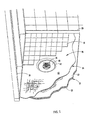
- Fig. 1 a top perspective view of a shower base installation, with a portion of the tile and grout removed to better show the shower base, including connection of the shower base to the floor drain.
- Fig. 2 is a cross-sectional view of the installation of the shower base of Fig. 1 .
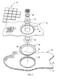
- Fig. 3 is an exploded view of Fig. 1 .
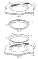
- Fig. 4 is a cross-sectional view of a honeycomb blank machined/routed to a desired shape.
- Figs. 5-6 are perspective and cross-sectional views of the injection molded ABS plastic insert for matably setting in the ring depression in the routed honeycomb component of Fig. 4 .
- Fig. 7 is a cross-sectional view of a subassembly of the routed honeycomb component and insert from Figs. 4-6 .
- Fig. 8 is a side cross-sectional view of the subassembly of Fig. 7 including a thermoformed waterproof member with scrim attached to same.
- a manufactured shower base assembly 20 ( Fig. 1 ) includes a thermoplastic honeycomb structure 21 with a spun bond polyester fabric 22 bonded to its base (bottom) surface.
- the illustrated polyester fabric has a typical tensile strength of 175 psi.
- the upper surface 23 of the honeycomb structure is contoured to a desired slope and drain opening configuration, and includes a thermoplastic pre-formed thermoplastic waterproof membrane 24 supported on and potentially integrally bonded to its upper surface 23.
- the waterproof membrane 24 is contoured to conform to a shape of the upper surface 23 of the honeycomb structure 21.
- a molded polymeric structural ring 25 includes a perimeter flange 26 that fits into a mating recess in the upper surface 23 of the honeycomb structure 21 and further includes a downwardly extending sleeve 27 that extends toward the drain opening 28.
- the structural ring 25 is utilized to provide added structure to the honeycomb structure 21 around the drain opening 28.
- the configuration allows for adjustment when placing/installing the shower base assembly 20 in relation to walls 31 of the shower enclosure 30 and to a floor drain 35 in the shower enclosure 30, and further allows for attachment to any common clamping ring style drain (with upper and lower clamping members 33-34 around floor drain 35), and provides for efficient and quick installation with minimization of skilled labor time.
- An edge seal 29 is bonded around a perimeter of the base assembly 20 and extends up under the shower's wall board to create a natural gravitational flow for water from the shower walls 31 onto the waterproof membrane 24 and toward the drain 35.
- the membrane 24 includes a center depressed area defined by a recessed flat panel portion 40, and a cascading portion 41 that extends from the lightly-sloped top main portion 42 toward the panel portion 40, the cascading portion 41 generally engaging and being supported by the inner surface of the ring 25.
- a sand mortar mix 43 is used to fill in around the floor drain 35 so that a generally continuous surface is formed from the main portion 42 all the way to a location immediately adjacent the exposed drain hole of the floor drain. (See Fig. 1 .)
- the illustrated waterproof membrane 24 is thermoplastic sheet product about 40 mil thick and extruded of CPE/PVC alloy.
- the membrane 24 includes a polyester scrim material having a weight of at least 50 grams per square meter on its upper surface to facilitate bonding of tile and grout.
- a suitable waterproof membrane is made by Noble Company as Noble DeckTM.
- the waterproof membrane has a permience rating of less than .0.040 perm per ASTM standard test method E96 Method E.
- the illustrated waterproof membrane 24 is made of a CPE/PVC material, and is commercially available such as from the Noble Company. It includes the following physical characteristics: Hardness ASTM D 2240 - 83 Shore A, Tensile Strength ASTM D 412 Die C 1450 psi, Elongation ASTM D 412 Die C 59%, Shear Strength Water Immersion 100 days ANSI 118.10 - 1999 PASS, Tear Strength ASTM D 624 Die C 375 psi.
- the illustrated base assembly 20 has a thickness dimension at its perimeter of about 4 inches, and a slope of about 1/4" per foot toward the recess for ring 25.
- the ring 25 (and mating recess) has an outer diameter of about 12 inches, and a depth of about 1 1/4".
- the drain opening in the honeycomb structure 21 is about 12 9/32".
- Tile and grout 37 are installed onto the waterproof membrane 24 using a latex-modified thin set bonding material to provide a durable aesthetic covering.
- the tile and grout 37 are very very sensitive to any deflection.
- rigidity and stability is very important in the supporting structure, which the present shower base assembly 20 provides.
- Installation of the assembly 20 is also very cost-effective and efficient, thus providing advantages of pre-construction of components/assembly at a factory and much easier (and faster) install at the job site.
- the present assembly 20 is light weight and can be trimmed at a j ob site if it is slightly oversized, which is another advantage.
- the present shower honeycomb structure 21 has its upper surface routed to include a drain opening 28 and routed to include a ring-shaped recess around the drain opening 28 for receiving the structural ring 25, and further routed to include a contoured top surface sloping toward the drain opening 28.
- An injection molded solid ring 25 of ABS material (see Figs. 5-8 ) is set into the drain opening 28.
- a thermoformed waterproof membrane (see Figs. 1 and 8 ) is placed on and bonded to the honeycomb structure 21. All this is preferably done at the factory where various dimensional changes can easily be made.
- the pre-fabricated base assembly 20 is placed in a shower stall/enclosure 30 having a drain 35 and stud walls 31. After installation, the wall board is placed, and a seal 29 is placed at a lower edge of the wall board and bonded to the membrane 24 so that water naturally flows away from the walls 31 (down an incline) toward the drain 35.
- the drain opening 28 can be cut into the base assembly at the factory, and that edges of the base assembly 20 can be trimmed if necessary to facilitate tight fit of the base assembly 20 into the shower stall. However, it is contemplated that the drain opening 28 can be cut at the installation site if desired. Further, it is contemplated that the fabric 22, honeycomb structure 21, and waterproof membrane 24 will be bonded at the factory. However, it is contemplated that one or more of these components could be bonded on site using adhesives and bonding agents. The area around the drain, inside the recess in the waterproof membrane is filled with appropriate filler material as necessary to support the tile adjacent the drain cover 35.
- the present assembly allows quick installation (i.e., new constructions, or retrofits/upgrades). It is particularly well suited for hotels that are being upgraded to eliminate old tubs, and to put into place showers and etc.
- the upgrade construction includes a first preparation of the floor, and then waiting for a day (or more) before coming back (once or more) to finish the job.
- a method of installing the shower base includes steps of providing a manufactured shower base assembly 20 including a thermoplastic honeycomb structure with a fabric bonded to its base surface and an upper surface contoured to a desired slope and drain opening configuration.
- a structural ring engages the upper surface and supports portions of the honeycomb structure adjacent the drain opening and a pre-formed thermoplastic waterproof membrane is supported on the upper surface.
- the membrane is contoured to conform to a shape of the honeycomb structure and to drain moisture toward the drain opening.
- a horizontal location of the shower base assembly is adjusted when placing and installing the shower base assembly in relation to walls of a shower enclosure and to a floor drain in the shower enclosure.
- a ring style drain is clamped to panel portions of the waterproof membrane that extend horizontally adjacent the drain opening and tile and grout is installed on the waterproof membrane to form a shower floor with drain.
- the present pre-fabricated assembly 20 brings profit content back from installation sites to a factory, yet produces a lower cost assembly due to simplified and improved installation, including less total time required by skilled labor.
- the present honeycomb structure provides a very good vertical stability (i.e., less compression) than installations that utilize polystyrene foam and other foams, such that the tiles and grout have much less tendency to crack in the present base assembly 20.
- an alternate waterproof membrane with impact sound reduction characteristics may be used in place of membrane 24.
- One such sound insulating membrane is Gaffigan 6,077,613.
- the shower base apparatus When used as the waterproof membrane 24, the shower base apparatus will provide a minimum ASTM 2179 sound reduction value of 12 in addition to providing adequate permience rating.
Abstract
Description
- This application claims benefit under 35 U.S.C. § 119(e) of provisional application serial no.
61/142,947, filed January 7, 2009 - The present invention relates to a prefabricated shower base assembly for tile and stone applications in showers.
- Tile and stone covered showers have been used for many years; however, construction methods for constructing showers and wet areas have changed dramatically such that construction of a sub-base is necessary to provide support for tile or stone floor surfaces. For example, waterproofing beneath the tile or stone is particularly necessary in multi-story constructions with living space beneath the shower area. This led to the creation/use of waterproof envelopes/barriers under the tile or stone, known as "shower pans." Early shower pans were constructed of copper, sheet metal or sheet lead, and were clamped to the drain typically with a clamping flange. These pans were then filled with a Portland cement and sand mixture, so that, when cured, they provided a base that was acceptable for bonding tile and stone. However, these types of shower pans were/are difficult and time-consuming to construct, and they were/are prone to leaking.
- As new materials came into existence, better waterproofing systems evolved such as liquid and thermoplastic membranes that provided superior waterproofing characteristics and that made installation easier over traditional lead and copper pans. Although this improved the integrity of the waterproofing, it still requires skilled labor to install the mortar bed on the pan. It also requires curing of the mortar bed prior to installation of the tile or stone, which takes time and potentially leads to inefficient use of skilled manpower due to the necessity of more than one visit by the skilled workers to the installations.
- As land and infrastructure costs have increased, residential homes and condominiums of multi-floor design have also increased. However, this increased density has created problems in the area of sound transmission between floors and ceilings of units above and below. The sound created by normal activity is transmitted through floors and is typically referred to as "Impact Sound." Bathrooms tend to be difficult areas to reduce the level of impact sound transmission to the unit below since a majority of bathroom areas are covered with ceramic tile or natural stone where transmission of sound through the floor becomes an issue. Since virtually all sound reduction materials are installed under the finish flooring, the area under a shower floor is not able to be isolated. Also, many bathroom "furniture" and structural articles, such as ceramic and/or metal toilets, tubs, sinks, countertops and pipes, can be sound generators and/or sound carriers, making it difficult to achieve a satisfactorily "quiet" bathroom area.
- In the United States and Canada, the most common drain that is used in shower and wet area installations is the "clamping ring drain." They are typically manufactured in cast iron, PVC and ABS materials and are available from a vast number of distributors and outlets. Depending on local building codes, installation of the drain most often falls under the plumbing code. However, the responsibility for the waterproof integrity and flood testing of the installation most often lies on the plumber. This requires coordination of skilled trades, which can lead to inefficiencies and hence higher costs during installation.
- Some companies have attempted to provide pre-manufactured shower bases and trays, attempting to reduce the amount of skilled labor time required for installations. However, the existing known pre-manufactured shower bases and trays do not permit adjustment in a baclc-to-front direction, nor in a side-to-side direction, nor diagonally, in order to match drain (and wall) locations. Floor drains also cannot be adjusted once rough-in piping is set during early stages of construction. Thus, in known systems, the floor drain must be precisely located in the shower floor relative to shower walls during building construction, and the location of the drain opening in pre-manufactured shower bases must be accurately cut to match, which is very difficult to do on a consistent basis in "real world" building constructions. Further, pre-manufactured shower bases and trays often still require repeated trips back to the installation site by skilled trades, thus still resulting in greater installation costs than desired. Still further, grout and tile are relatively brittle and very sensitive to any deflection, which leads to cracking when the floor flexes or is stressed, which in turn leads to water leak problems. Thus, rigidity and stability is very important in the supporting structure. Yet some pre-manufactured shower bases arguably provide only marginal rigidity and stability.
- A manufactured shower base assembly includes a thermoplastic honeycomb structure with a spun bond polyester fabric bonded to its base surface. The upper surface of the honeycomb structure is contoured to a desired slope and drain opening configuration, and includes a thermoplastic pre-formed thermoplastic waterproof membrane integrally bonded to its top surface, the membrane being contoured to conform to a shape of the honeycomb structure. A structural ring is utilized to provide added structure around the drain opening. The configuration allows for adjustment when placing/installing the shower base in relation to walls of the shower enclosure and to a floor drain in the shower enclosure, and further allows for attachment to any common clamping ring style drain, yet provides for efficient and quick installation with minimization of skilled labor time.
- In one aspect of the present invention, a shower base assembly includes a honeycomb structure with a synthetic material bonded to its lower surface and having a contoured upper surface defining a drain opening. A formed thermoplastic waterproof membrane is supported on the honeycomb surface and has a shape matching the contoured upper surface. The waterproof membrane has an exposed surface constructed to allow tile and stone to be directly bonded to the exposed surface.
- In another aspect of the present invention, a manufactured shower base includes a thermoplastic honeycomb structure with a fabric bonded to its base surface and an upper surface contoured to a desired slope and drain opening configuration. A structural ring engages the upper surface and supports portions of the honeycomb structure adjacent the drain opening. A pre-formed thermoplastic membrane is supported on the upper surface, the membrane being contoured to conform to a shape of the honeycomb structure and to drain moisture toward the drain opening. In a narrower form, the membrane forms a waterproof layer.
- In another aspect of the present invention, a method of installing a shower base comprises steps of providing a manufactured shower base assembly including a thermoplastic honeycomb structure with a fabric bonded to its base surface and an upper surface contoured to a desired slope and drain opening configuration, a structural ring engaging the upper surface and supporting portions of the honeycomb structure adjacent the drain opening, and a pre-formed thermoplastic waterproof membrane supported on the upper surface, the membrane being contoured to conform to a shape of the honeycomb structure and to drain moisture toward the drain opening. The method further includes adjusting a horizontal location of the shower base assembly when placing and installing the shower base assembly in relation to walls of a shower enclosure and to a floor drain in the shower enclosure, and clamping a ring style drain to panel portions of the waterproof membrane that extend horizontally adjacent the drain opening. The method further includes installing tile and grout on the waterproof membrane to form a shower floor with drain.
- These and other aspects, objects, and features of the present invention will be understood and appreciated by those skilled in the art upon studying the following specification, claims, and appended drawings.
- Preferred embodiments of the present invention will now be described by way of example only with reference to the accompanying drawings, in which:
-
Fig. 1 a top perspective view of a shower base installation, with a portion of the tile and grout removed to better show the shower base, including connection of the shower base to the floor drain. -
Fig. 2 is a cross-sectional view of the installation of the shower base ofFig. 1 . -
Fig. 3 is an exploded view ofFig. 1 . -
Fig. 4 is a cross-sectional view of a honeycomb blank machined/routed to a desired shape. -
Figs. 5-6 are perspective and cross-sectional views of the injection molded ABS plastic insert for matably setting in the ring depression in the routed honeycomb component ofFig. 4 . -
Fig. 7 is a cross-sectional view of a subassembly of the routed honeycomb component and insert fromFigs. 4-6 . -
Fig. 8 is a side cross-sectional view of the subassembly ofFig. 7 including a thermoformed waterproof member with scrim attached to same. - A manufactured shower base assembly 20 (
Fig. 1 ) includes athermoplastic honeycomb structure 21 with a spunbond polyester fabric 22 bonded to its base (bottom) surface. The illustrated polyester fabric has a typical tensile strength of 175 psi. Theupper surface 23 of the honeycomb structure is contoured to a desired slope and drain opening configuration, and includes a thermoplastic pre-formed thermoplasticwaterproof membrane 24 supported on and potentially integrally bonded to itsupper surface 23. Thewaterproof membrane 24 is contoured to conform to a shape of theupper surface 23 of thehoneycomb structure 21. A molded polymericstructural ring 25 includes aperimeter flange 26 that fits into a mating recess in theupper surface 23 of thehoneycomb structure 21 and further includes a downwardly extendingsleeve 27 that extends toward thedrain opening 28. Thestructural ring 25 is utilized to provide added structure to thehoneycomb structure 21 around thedrain opening 28. - The configuration allows for adjustment when placing/installing the
shower base assembly 20 in relation towalls 31 of theshower enclosure 30 and to afloor drain 35 in theshower enclosure 30, and further allows for attachment to any common clamping ring style drain (with upper and lower clamping members 33-34 around floor drain 35), and provides for efficient and quick installation with minimization of skilled labor time. Anedge seal 29 is bonded around a perimeter of thebase assembly 20 and extends up under the shower's wall board to create a natural gravitational flow for water from theshower walls 31 onto thewaterproof membrane 24 and toward thedrain 35. Themembrane 24 includes a center depressed area defined by a recessedflat panel portion 40, and a cascadingportion 41 that extends from the lightly-sloped topmain portion 42 toward thepanel portion 40, the cascadingportion 41 generally engaging and being supported by the inner surface of thering 25. Asand mortar mix 43 is used to fill in around thefloor drain 35 so that a generally continuous surface is formed from themain portion 42 all the way to a location immediately adjacent the exposed drain hole of the floor drain. (SeeFig. 1 .) - The illustrated
waterproof membrane 24 is thermoplastic sheet product about 40 mil thick and extruded of CPE/PVC alloy. Themembrane 24 includes a polyester scrim material having a weight of at least 50 grams per square meter on its upper surface to facilitate bonding of tile and grout. For example, a suitable waterproof membrane is made by Noble Company as Noble Deck™. The waterproof membrane has a permience rating of less than .0.040 perm per ASTM standard test method E96 Method E. - The illustrated
waterproof membrane 24 is made of a CPE/PVC material, and is commercially available such as from the Noble Company. It includes the following physical characteristics: Hardness ASTM D 2240 - 83 Shore A, Tensile Strength ASTM D 412 Die C 1450 psi, Elongation ASTM D 412 Die C 59%, Shear Strength Water Immersion 100 days ANSI 118.10 - 1999 PASS, Tear Strength ASTM D 624 Die C 375 psi. - The illustrated
base assembly 20 has a thickness dimension at its perimeter of about 4 inches, and a slope of about 1/4" per foot toward the recess forring 25. The ring 25 (and mating recess) has an outer diameter of about 12 inches, and a depth of about 1 1/4". The drain opening in thehoneycomb structure 21 is about 12 9/32". The honeycomb structure and waterproof membrane combine to have a compressive strength of at least about 200 psi (and preferably of 235 psi) with less than about L/720 deflection where L= a length of the shower base. Bonding of thefabric 22 andwaterproof membrane 24 to the honeycomb structure provides a beam-like strength to the assembly. - Tile and
grout 37 are installed onto thewaterproof membrane 24 using a latex-modified thin set bonding material to provide a durable aesthetic covering. Notably, the tile andgrout 37 are very very sensitive to any deflection. Thus, rigidity and stability is very important in the supporting structure, which the presentshower base assembly 20 provides. Installation of theassembly 20 is also very cost-effective and efficient, thus providing advantages of pre-construction of components/assembly at a factory and much easier (and faster) install at the job site. Further, thepresent assembly 20 is light weight and can be trimmed at a j ob site if it is slightly oversized, which is another advantage. - The present shower honeycomb structure 21 (see
Fig. 4 ) has its upper surface routed to include adrain opening 28 and routed to include a ring-shaped recess around thedrain opening 28 for receiving thestructural ring 25, and further routed to include a contoured top surface sloping toward thedrain opening 28. An injection moldedsolid ring 25 of ABS material (seeFigs. 5-8 ) is set into thedrain opening 28. A thermoformed waterproof membrane (seeFigs. 1 and8 ) is placed on and bonded to thehoneycomb structure 21. All this is preferably done at the factory where various dimensional changes can easily be made. At the installation, thepre-fabricated base assembly 20 is placed in a shower stall/enclosure 30 having adrain 35 andstud walls 31. After installation, the wall board is placed, and aseal 29 is placed at a lower edge of the wall board and bonded to themembrane 24 so that water naturally flows away from the walls 31 (down an incline) toward thedrain 35. - It is contemplated that the
drain opening 28 can be cut into the base assembly at the factory, and that edges of thebase assembly 20 can be trimmed if necessary to facilitate tight fit of thebase assembly 20 into the shower stall. However, it is contemplated that thedrain opening 28 can be cut at the installation site if desired. Further, it is contemplated that thefabric 22,honeycomb structure 21, andwaterproof membrane 24 will be bonded at the factory. However, it is contemplated that one or more of these components could be bonded on site using adhesives and bonding agents. The area around the drain, inside the recess in the waterproof membrane is filled with appropriate filler material as necessary to support the tile adjacent thedrain cover 35. - The present assembly allows quick installation (i.e., new constructions, or retrofits/upgrades). It is particularly well suited for hotels that are being upgraded to eliminate old tubs, and to put into place showers and etc. In prior art, the upgrade construction includes a first preparation of the floor, and then waiting for a day (or more) before coming back (once or more) to finish the job.
- A method of installing the shower base includes steps of providing a manufactured
shower base assembly 20 including a thermoplastic honeycomb structure with a fabric bonded to its base surface and an upper surface contoured to a desired slope and drain opening configuration. A structural ring engages the upper surface and supports portions of the honeycomb structure adjacent the drain opening and a pre-formed thermoplastic waterproof membrane is supported on the upper surface. The membrane is contoured to conform to a shape of the honeycomb structure and to drain moisture toward the drain opening. A horizontal location of the shower base assembly is adjusted when placing and installing the shower base assembly in relation to walls of a shower enclosure and to a floor drain in the shower enclosure. A ring style drain is clamped to panel portions of the waterproof membrane that extend horizontally adjacent the drain opening and tile and grout is installed on the waterproof membrane to form a shower floor with drain. - Notably, the present
pre-fabricated assembly 20 brings profit content back from installation sites to a factory, yet produces a lower cost assembly due to simplified and improved installation, including less total time required by skilled labor. The present honeycomb structure provides a very good vertical stability (i.e., less compression) than installations that utilize polystyrene foam and other foams, such that the tiles and grout have much less tendency to crack in thepresent base assembly 20. - Where construction criteria calls for reduced impact sound, an alternate waterproof membrane with impact sound reduction characteristics may be used in place of
membrane 24. One such sound insulating membrane is Gaffigan 6,077,613. When used as thewaterproof membrane 24, the shower base apparatus will provide a minimum ASTM 2179 sound reduction value of 12 in addition to providing adequate permience rating. - It is to be understood that variations and modifications can be made on the aforementioned structure without departing from the concepts of the present invention, and further it is to be understood that such concepts are intended to be covered by the following claims unless these claims by their language expressly state otherwise.
Claims (15)
- A shower base assembly comprising:a honeycomb structure with a synthetic material bonded to its lower surface and having a contoured upper surface defining a drain opening; anda formed thermoplastic waterproof membrane supported on the honeycomb surface and having a shape matching the contoured upper surface, the waterproof membrane having an exposed surface constructed to allow tile and stone to be directly bonded to the exposed surface.
- The shower base assembly defined in claim 1, wherein the contoured upper surface is sloped toward the drain opening such that the waterproof membrane allows any water that penetrates the tile or stone to flow horizontally through capillary action into weep holes of a clamping ring drain.
- The shower based assembly defined in claim 1 or claim 2, wherein the waterproof membrane and the synthetic material are mechanically bonded.
- The shower base assembly defined in any one of the preceding claims, including a molded insert ring bonded to the honeycomb structure to provide added support around the drain opening for the formed waterproof membrane.
- The shower base assembly defined in any one of the preceding claims, wherein the waterproof membrane includes a panel portion extending across the drain opening and is adapted for mechanical attachment to conventional clamping ring drains.
- The shower base assembly defined in claim 5, wherein the panel portion extends generally parallel the lower surface at a location where the honeycomb structure is completely cut away, the panel portion including a hole cut to match a location of a drain floor and having a perimeter portion adapted to be clampingly engaged by a conventional clamping ring drain.
- The shower base assembly defined in any one of the preceding claims, including a synthetic material on a lower surface of the honeycomb structure that allows for bonding said lower surface to a subfloor in a shower construction.
- The shower base assembly defined in any one of the preceding claims, including an injection molded structural ring of solid plastic material positioned in a recess in the honeycomb structure around the drain opening.
- The shower base assembly defined in claim 8, wherein the molded structural ring includes a perimeter ring portion that fits into a mating recess in the contoured upper surface of the honeycomb structure and further includes a sleeve ring portion that extends downwardly toward the drain opening.
- The shower base assembly defined in any one of the preceding claims, wherein the synthetic material on the honeycomb structure is a scrim material.
- The shower base assembly defined in any one of the preceding claims, wherein the honeycomb structure including a plurality of walls that extend vertically between the lower surface and the contoured upper surface, and further that, when cross-sectioned horizontally, define a plurality of interconnected honeycomb shapes.
- The shower base assembly defined in any one of the preceding claims, including a drain hold formed by the waterproof membrane, and lower clamping components clamped onto the waterproof membrane around the drain hole.
- A manufactured shower base includes a thermoplastic honeycomb structure with a fabric bonded to its base surface and an upper surface contoured to a desired slope and drain opening configuration;
a structural ring engaging the upper surface and supporting portions of the honeycomb structure adjacent the drain opening; and
a pre-formed thermoplastic membrane supported on the upper surface, the membrane being contoured to conform to a shape of the honeycomb structure and to drain moisture toward the drain opening. - The shower base defined in claim 13, wherein the membrane forms a waterproof layer.
- A method of installing a shower base, comprising steps of:providing a manufactured shower base assembly including a thermoplastic honeycomb structure with a fabric bonded to its base surface and an upper surface contoured to a desired slope and drain opening configuration, a structural ring engaging the upper surface and supporting portions of the honeycomb structure adjacent the drain opening, and a pre-formed thermoplastic waterproof membrane supported on the upper surface, the membrane being contoured to conform to a shape of the honeycomb structure and to drain moisture toward the drain opening;adjusting a horizontal location of the shower base assembly when placing and installing the shower base assembly in relation to walls of a shower enclosure and to a floor drain in the shower enclosure;clamping a ring style drain to panel portions of the waterproof membrane that extend horizontally adjacent the drain opening; andinstalling tile and grout on the waterproof membrane to form a shower floor with drain.
Applications Claiming Priority (2)
| Application Number | Priority Date | Filing Date | Title |
|---|---|---|---|
| US14294709P | 2009-01-07 | 2009-01-07 | |
| US12/652,224 US8230535B2 (en) | 2009-01-07 | 2010-01-05 | Shower base apparatus |
Publications (2)
| Publication Number | Publication Date |
|---|---|
| EP2206456A2 true EP2206456A2 (en) | 2010-07-14 |
| EP2206456A3 EP2206456A3 (en) | 2016-12-07 |
Family
ID=42034559
Family Applications (1)
| Application Number | Title | Priority Date | Filing Date |
|---|---|---|---|
| EP10150233.4A Withdrawn EP2206456A3 (en) | 2009-01-07 | 2010-01-07 | Shower base assembly |
Country Status (3)
| Country | Link |
|---|---|
| US (1) | US8230535B2 (en) |
| EP (1) | EP2206456A3 (en) |
| CA (1) | CA2689796C (en) |
Cited By (9)
| Publication number | Priority date | Publication date | Assignee | Title |
|---|---|---|---|---|
| GB2482492A (en) * | 2010-08-03 | 2012-02-08 | Jet Ltd Spa | Reinforced shower tray |
| CN103025971A (en) * | 2010-07-28 | 2013-04-03 | 菲利普·约翰·缪尔黑德 | Improved waste fitting |
| EP2425755A3 (en) * | 2010-09-03 | 2013-07-03 | Harald Schendzielorz | Shower tray |
| WO2014096849A1 (en) * | 2012-12-21 | 2014-06-26 | Riverbed Limited | Shaped floor former |
| WO2014176402A1 (en) * | 2013-04-26 | 2014-10-30 | United States Gypsum Company | Integrated bonding flange support disk for prefabricated shower tray |
| US9731441B2 (en) | 2013-04-26 | 2017-08-15 | MGNT Products Group, LLC | Double fabric faced injection molded fixture |
| WO2018080973A1 (en) * | 2016-10-24 | 2018-05-03 | Noble Company | Damage-resistant shower base and installation method |
| US10920410B2 (en) | 2017-12-04 | 2021-02-16 | Noble Manufacturing, LLC | Trench drain providing variable drain location and installation |
| DE102020100489A1 (en) | 2020-01-10 | 2021-07-15 | Franz Kaldewei Gmbh & Co. Kg | Shower space construction, shower space and method for creating a shower space |
Families Citing this family (28)
| Publication number | Priority date | Publication date | Assignee | Title |
|---|---|---|---|---|
| US8181288B1 (en) * | 2007-06-04 | 2012-05-22 | KBRS Manufacturing, Inc. | Waterproof base and methods of fabrication and installation thereof |
| NL2001410C2 (en) * | 2008-03-27 | 2009-09-03 | Assenti Lux S A | Method, device, material layer and collection of parts for sealing a drain gutter. |
| US20100071125A1 (en) * | 2008-09-19 | 2010-03-25 | Gary Miller | Modular Shower Water-Proofing System and Method of Use |
| DE202010002332U1 (en) * | 2010-02-12 | 2010-09-30 | Wedi Gmbh | Substructure element for underlaying a shower floor element |
| US20120199709A1 (en) * | 2011-02-03 | 2012-08-09 | Rompel Wade D | Tile-ready structural support ledge for ceramic tile shelves |
| DE202011005194U1 (en) * | 2011-04-13 | 2011-08-30 | Wedi Gmbh | Foreign soil element with wedge-shaped reinforcement in the edge area |
| US10243121B2 (en) | 2011-06-24 | 2019-03-26 | Cree, Inc. | High voltage monolithic LED chip with improved reliability |
| CA2795948C (en) | 2011-11-18 | 2020-01-07 | Schluter Systems L.P. | Tileable drain systems and related methods |
| US8875727B2 (en) | 2012-02-09 | 2014-11-04 | Zurn Industries, Llc | Rough-in adapter clip lock for a drain assembly |
| US9179807B2 (en) | 2012-09-14 | 2015-11-10 | Sonoco Development, Inc. | Support for shower pan or tub |
| US9428900B2 (en) | 2012-10-31 | 2016-08-30 | Zurn Industries, Llc | Rough-in adapter |
| US10182684B2 (en) | 2013-02-19 | 2019-01-22 | Davis Intellectual Assets, Llc | Composite shower curb and self-sealing curb cap |
| DE102014113094A1 (en) * | 2014-09-11 | 2016-03-17 | Wedi Gmbh | Shower floor panel module with receiving element for a shower cup screw valve |
| EP2998517B1 (en) * | 2014-09-16 | 2019-03-27 | Ansaldo Energia Switzerland AG | Sealing arrangement at the interface between a combustor and a turbine of a gas turbine and gas turbine with such a sealing arrangement |
| US10658546B2 (en) | 2015-01-21 | 2020-05-19 | Cree, Inc. | High efficiency LEDs and methods of manufacturing |
| DE102015102247B4 (en) | 2015-02-17 | 2018-09-20 | Wedi Gmbh | Shower floor plate module |
| US10676911B2 (en) * | 2016-12-15 | 2020-06-09 | Qd Holdings I Llc | Recessed point drain assembly |
| US10758093B2 (en) * | 2017-03-31 | 2020-09-01 | Estil Guru S.L. | Device for connecting a waterproofing to a built-in shower drain and a waterproofing assembly |
| US10463201B2 (en) * | 2017-07-12 | 2019-11-05 | Roger Acers | Shower related apparatus |
| US10794052B2 (en) * | 2018-02-07 | 2020-10-06 | Christopher Adam McLeod | Cup and saucer thinset surface drain |
| US11168232B2 (en) | 2018-02-23 | 2021-11-09 | Ardex Group Gmbh | Methods of installing tile using a reactivatable tile bonding mat |
| US10856702B2 (en) * | 2018-05-26 | 2020-12-08 | KurbX LLC | Systems and methods for a shower base assembly compatible with residential and commercial construction |
| US11284751B2 (en) | 2018-05-26 | 2022-03-29 | Kurbx, Llc | Shower base assembly compatible with residential and commercial construction |
| US10779688B1 (en) * | 2018-12-10 | 2020-09-22 | Avery S. Herring | One piece tileable shower unit |
| EP4027845A4 (en) | 2019-09-13 | 2024-02-21 | Welch Tile & Marble Co | Shower base system |
| US11712135B2 (en) | 2020-04-30 | 2023-08-01 | Kohler Co. | Field trimmable receptor |
| US20220290419A1 (en) * | 2021-03-09 | 2022-09-15 | Ardex, L.P. | Drain Device and Shower Base System |
| WO2022251301A1 (en) * | 2021-05-27 | 2022-12-01 | As America, Inc. | Bath or shower enclosure walls |
Family Cites Families (29)
| Publication number | Priority date | Publication date | Assignee | Title |
|---|---|---|---|---|
| US2292368A (en) * | 1939-10-19 | 1942-08-11 | Porcelain Metals Corp | Vitreous enamel bath floor |
| US2836830A (en) * | 1957-04-16 | 1958-06-03 | Glenn E Norman | Tile receptor for showers |
| US3139627A (en) * | 1962-08-08 | 1964-07-07 | Rubber And Plastics Compound C | Liner for a shower stall |
| US4198715A (en) * | 1978-10-30 | 1980-04-22 | Novi Plastics Company | Shower cabinet and base |
| US4280613A (en) * | 1979-10-12 | 1981-07-28 | Canron Corp. | Tie plate conveying and orientating system |
| US4557004A (en) * | 1984-06-28 | 1985-12-10 | Piana Angelo J | Waterproof shower module with tile-ready inner surfaces |
| US4571751A (en) * | 1984-12-24 | 1986-02-25 | Barlow J Bruce | Drain assembly with synthetic resin lock nut and coupling elements |
| US4844944A (en) * | 1987-12-18 | 1989-07-04 | American Standard, Inc. | Lightweight, durable plumbing fixture fabricated from a delamination-resistant multilayer polymeric composite |
| US5140789A (en) * | 1989-10-10 | 1992-08-25 | Gooyer Lonnie C De | Underlay for tile floor of shower |
| US6077613A (en) * | 1993-11-12 | 2000-06-20 | The Noble Company | Sound insulating membrane |
| US5643652A (en) * | 1994-09-28 | 1997-07-01 | Centura Solid Surfacing, Inc. | Composite panel for toilet and shower partitions |
| US5845347A (en) * | 1995-03-06 | 1998-12-08 | Young; David A. | Method of manufacturing shower foundation |
| US5816005A (en) * | 1996-09-04 | 1998-10-06 | Han; Eddie Eui In | Pre-fabricated title board |
| US5913777A (en) * | 1997-05-12 | 1999-06-22 | Tile Redi, Ltd. | Pre-fabricated shower module and method of shower construction |
| NZ510443A (en) * | 2001-03-09 | 2003-10-31 | Gregory John Smale | Drainage surface construction formed from self- supporting members having sloping upper surfaces |
| US6447565B1 (en) * | 2001-05-03 | 2002-09-10 | General Motors Corporation | Transmission vent assembly |
| US20030003271A1 (en) * | 2001-07-02 | 2003-01-02 | Bykov Vladimir M. | Concrete and plastic construction panel |
| DE202005018684U1 (en) * | 2004-09-30 | 2006-03-23 | Illbruck Sanitärtechnik GmbH | Base for shower tray, comprising adhesion promoting layer of high density attached to bottom layer |
| USD539394S1 (en) * | 2005-05-20 | 2007-03-27 | Dlp Limited | Trim-to-fit shower base |
| US20070294954A1 (en) * | 2006-06-22 | 2007-12-27 | Barrett Jeffrey L | Prefabricated bathroom assembly and methods of its manufacture and installation |
| GB2444492B (en) * | 2006-07-15 | 2011-07-20 | Dlp Ltd | Height adjustable shower waste |
| CA2553168C (en) * | 2006-07-19 | 2011-01-04 | Madison Daniels | Modular shower pan |
| US8141182B2 (en) * | 2007-03-17 | 2012-03-27 | Cook Joseph R | Method of manufacturing and installation of prefabricated shower bench and associated shower bench |
| US8209795B2 (en) * | 2007-03-17 | 2012-07-03 | Cook Joseph R | Prefabricated shower pan having varying sidewall heights and method of attaching a modular curb |
| US8181286B2 (en) * | 2007-03-17 | 2012-05-22 | Cook Joseph R | Drain wall for a prefabricated shower module |
| US20080222793A1 (en) * | 2007-03-17 | 2008-09-18 | Tile Redi, Llc | Ribbed prefabricated polyurethane shower module |
| US8141183B2 (en) * | 2007-03-17 | 2012-03-27 | Cook Joseph R | Method for manufacturing a prefabricated modular shower curb and associated modular shower curb |
| US8375480B2 (en) * | 2007-03-17 | 2013-02-19 | Tile Redi, Llc | Method for manufacturing a prefabricated shower module |
| US20080276364A1 (en) * | 2007-05-07 | 2008-11-13 | Barro James S | Manufactured Shower Pan |
-
2010
- 2010-01-05 US US12/652,224 patent/US8230535B2/en active Active
- 2010-01-06 CA CA2689796A patent/CA2689796C/en not_active Expired - Fee Related
- 2010-01-07 EP EP10150233.4A patent/EP2206456A3/en not_active Withdrawn
Non-Patent Citations (1)
| Title |
|---|
| None |
Cited By (17)
| Publication number | Priority date | Publication date | Assignee | Title |
|---|---|---|---|---|
| CN103025971A (en) * | 2010-07-28 | 2013-04-03 | 菲利普·约翰·缪尔黑德 | Improved waste fitting |
| US10738447B2 (en) | 2010-07-28 | 2020-08-11 | Kellophie Ip Holdings Pty Ltd | Waste fitting |
| CN103025971B (en) * | 2010-07-28 | 2015-11-25 | 凯洛菲Ip控股私人有限公司 | Improvement waste discharge accessory |
| US9988800B2 (en) | 2010-07-28 | 2018-06-05 | Philip John Muirhead | Waste fitting |
| GB2482492A (en) * | 2010-08-03 | 2012-02-08 | Jet Ltd Spa | Reinforced shower tray |
| EP2425755A3 (en) * | 2010-09-03 | 2013-07-03 | Harald Schendzielorz | Shower tray |
| WO2014096849A1 (en) * | 2012-12-21 | 2014-06-26 | Riverbed Limited | Shaped floor former |
| US20160177561A1 (en) * | 2013-04-26 | 2016-06-23 | Mgnt Products Group Llc | Integrated Bonding Flange Support Disk for Prefabricated Shower Tray |
| US9307869B2 (en) | 2013-04-26 | 2016-04-12 | Mgnt Products Group Llc | Integrated bonding flange support disk for prefabricated shower tray |
| US9731441B2 (en) | 2013-04-26 | 2017-08-15 | MGNT Products Group, LLC | Double fabric faced injection molded fixture |
| US9771713B2 (en) | 2013-04-26 | 2017-09-26 | Mgnt Products Group Llc | Integrated bonding flange support disk for prefabricated shower tray |
| CN105358772B (en) * | 2013-04-26 | 2017-10-31 | 美国石膏公司 | Integrated flange bearing discoid pieces of bonding for prefabricated shower disc |
| CN105358772A (en) * | 2013-04-26 | 2016-02-24 | 美国石膏公司 | Integrated bonding flange support disk for prefabricated shower tray |
| WO2014176402A1 (en) * | 2013-04-26 | 2014-10-30 | United States Gypsum Company | Integrated bonding flange support disk for prefabricated shower tray |
| WO2018080973A1 (en) * | 2016-10-24 | 2018-05-03 | Noble Company | Damage-resistant shower base and installation method |
| US10920410B2 (en) | 2017-12-04 | 2021-02-16 | Noble Manufacturing, LLC | Trench drain providing variable drain location and installation |
| DE102020100489A1 (en) | 2020-01-10 | 2021-07-15 | Franz Kaldewei Gmbh & Co. Kg | Shower space construction, shower space and method for creating a shower space |
Also Published As
| Publication number | Publication date |
|---|---|
| CA2689796A1 (en) | 2010-07-07 |
| CA2689796C (en) | 2016-08-09 |
| US8230535B2 (en) | 2012-07-31 |
| EP2206456A3 (en) | 2016-12-07 |
| US20100170035A1 (en) | 2010-07-08 |
Similar Documents
| Publication | Publication Date | Title |
|---|---|---|
| CA2689796C (en) | Shower base apparatus | |
| CA2849593C (en) | Integrated bonding flange support disk for prefabricated shower tray | |
| US5913777A (en) | Pre-fabricated shower module and method of shower construction | |
| US8474068B2 (en) | Trench shower drain | |
| US5816005A (en) | Pre-fabricated title board | |
| US8918926B1 (en) | One piece shower pan and method of making same | |
| US10794052B2 (en) | Cup and saucer thinset surface drain | |
| DK2359727T3 (en) | Substructure element for laying a shower element | |
| JP2003529005A (en) | Building structure having floor drainage and floor drainage pipe | |
| US20100071125A1 (en) | Modular Shower Water-Proofing System and Method of Use | |
| KR101218810B1 (en) | Structure of prefabricated bathroom | |
| US20190100906A1 (en) | Floor drain with a hidden thread clamp. | |
| EP1857029A2 (en) | Floor element and method for making a floor element | |
| AU2020256635A1 (en) | Panel and panel assembly for modular wet area construction | |
| KR101716876B1 (en) | prefabricated Bathroom Floor Board | |
| KR101564993B1 (en) | Drain Assembled Bathroom Floor Board | |
| KR20160101767A (en) | Floor structure for prefabricated bathroom with weight lightening and the method thereof | |
| JPH0617460A (en) | Precast concrete floor block and water resistant pan | |
| KR101135564B1 (en) | Structure of prefabricated bathroom | |
| JP4672444B2 (en) | Waterproof pan for renovation | |
| KR101290817B1 (en) | Structure of prefabricated bathroom of discharge apparatus for leachate water | |
| CN115897737A (en) | Waterproof and drainage integrated part for toilet and manufacturing and mounting process thereof | |
| NZ746966A (en) | Shower base | |
| AU2018241063A1 (en) | Shower base | |
| KR20050120006A (en) | Wall-hung type water closet room housing method by using polyuretane skin wall panel---t-gps |
Legal Events
| Date | Code | Title | Description |
|---|---|---|---|
| PUAI | Public reference made under article 153(3) epc to a published international application that has entered the european phase |
Free format text: ORIGINAL CODE: 0009012 |
|
| AK | Designated contracting states |
Kind code of ref document: A2 Designated state(s): AT BE BG CH CY CZ DE DK EE ES FI FR GB GR HR HU IE IS IT LI LT LU LV MC MK MT NL NO PL PT RO SE SI SK SM TR |
|
| AX | Request for extension of the european patent |
Extension state: AL BA RS |
|
| PUAL | Search report despatched |
Free format text: ORIGINAL CODE: 0009013 |
|
| AK | Designated contracting states |
Kind code of ref document: A3 Designated state(s): AT BE BG CH CY CZ DE DK EE ES FI FR GB GR HR HU IE IS IT LI LT LU LV MC MK MT NL NO PL PT RO SE SI SK SM TR |
|
| AX | Request for extension of the european patent |
Extension state: AL BA RS |
|
| RIC1 | Information provided on ipc code assigned before grant |
Ipc: A47K 3/40 20060101AFI20161102BHEP |
|
| STAA | Information on the status of an ep patent application or granted ep patent |
Free format text: STATUS: THE APPLICATION HAS BEEN WITHDRAWN |
|
| 18W | Application withdrawn |
Effective date: 20170607 |