EP2206349B1 - Methods and apparatus for inter-layer residue prediction for scalable video - Google Patents
Methods and apparatus for inter-layer residue prediction for scalable video Download PDFInfo
- Publication number
- EP2206349B1 EP2206349B1 EP08839103.2A EP08839103A EP2206349B1 EP 2206349 B1 EP2206349 B1 EP 2206349B1 EP 08839103 A EP08839103 A EP 08839103A EP 2206349 B1 EP2206349 B1 EP 2206349B1
- Authority
- EP
- European Patent Office
- Prior art keywords
- tone mapping
- block
- prediction
- inverse tone
- bit depth
- Prior art date
- Legal status (The legal status is an assumption and is not a legal conclusion. Google has not performed a legal analysis and makes no representation as to the accuracy of the status listed.)
- Active
Links
- 238000000034 method Methods 0.000 title claims description 43
- 239000011229 interlayer Substances 0.000 title claims description 38
- 239000010410 layer Substances 0.000 claims description 65
- 238000013507 mapping Methods 0.000 claims description 60
- 230000008569 process Effects 0.000 claims description 9
- 238000009499 grossing Methods 0.000 claims description 4
- 230000000153 supplemental effect Effects 0.000 claims description 4
- 238000001914 filtration Methods 0.000 claims description 3
- 230000006870 function Effects 0.000 description 60
- 238000004891 communication Methods 0.000 description 32
- 230000008901 benefit Effects 0.000 description 15
- 239000013598 vector Substances 0.000 description 13
- 238000010586 diagram Methods 0.000 description 8
- 208000037170 Delayed Emergence from Anesthesia Diseases 0.000 description 6
- 238000013459 approach Methods 0.000 description 5
- 238000012545 processing Methods 0.000 description 3
- 230000011664 signaling Effects 0.000 description 2
- 102100032814 ATP-dependent zinc metalloprotease YME1L1 Human genes 0.000 description 1
- 101710161876 ATP-dependent zinc metalloprotease YME1L1 Proteins 0.000 description 1
- 230000006978 adaptation Effects 0.000 description 1
- 238000010420 art technique Methods 0.000 description 1
- 238000004422 calculation algorithm Methods 0.000 description 1
- 238000004364 calculation method Methods 0.000 description 1
- 239000003086 colorant Substances 0.000 description 1
- 239000000470 constituent Substances 0.000 description 1
- 238000013500 data storage Methods 0.000 description 1
- 238000003384 imaging method Methods 0.000 description 1
- 230000003993 interaction Effects 0.000 description 1
- 238000004519 manufacturing process Methods 0.000 description 1
- 230000008520 organization Effects 0.000 description 1
- 230000002093 peripheral effect Effects 0.000 description 1
- 238000012805 post-processing Methods 0.000 description 1
- 230000009467 reduction Effects 0.000 description 1
- 238000004088 simulation Methods 0.000 description 1
- 230000007704 transition Effects 0.000 description 1
Images

Classifications
-
- H—ELECTRICITY
- H04—ELECTRIC COMMUNICATION TECHNIQUE
- H04N—PICTORIAL COMMUNICATION, e.g. TELEVISION
- H04N19/00—Methods or arrangements for coding, decoding, compressing or decompressing digital video signals
- H04N19/50—Methods or arrangements for coding, decoding, compressing or decompressing digital video signals using predictive coding
- H04N19/59—Methods or arrangements for coding, decoding, compressing or decompressing digital video signals using predictive coding involving spatial sub-sampling or interpolation, e.g. alteration of picture size or resolution
-
- H—ELECTRICITY
- H04—ELECTRIC COMMUNICATION TECHNIQUE
- H04N—PICTORIAL COMMUNICATION, e.g. TELEVISION
- H04N19/00—Methods or arrangements for coding, decoding, compressing or decompressing digital video signals
- H04N19/10—Methods or arrangements for coding, decoding, compressing or decompressing digital video signals using adaptive coding
- H04N19/102—Methods or arrangements for coding, decoding, compressing or decompressing digital video signals using adaptive coding characterised by the element, parameter or selection affected or controlled by the adaptive coding
- H04N19/103—Selection of coding mode or of prediction mode
- H04N19/105—Selection of the reference unit for prediction within a chosen coding or prediction mode, e.g. adaptive choice of position and number of pixels used for prediction
-
- H—ELECTRICITY
- H04—ELECTRIC COMMUNICATION TECHNIQUE
- H04N—PICTORIAL COMMUNICATION, e.g. TELEVISION
- H04N19/00—Methods or arrangements for coding, decoding, compressing or decompressing digital video signals
- H04N19/10—Methods or arrangements for coding, decoding, compressing or decompressing digital video signals using adaptive coding
- H04N19/169—Methods or arrangements for coding, decoding, compressing or decompressing digital video signals using adaptive coding characterised by the coding unit, i.e. the structural portion or semantic portion of the video signal being the object or the subject of the adaptive coding
- H04N19/184—Methods or arrangements for coding, decoding, compressing or decompressing digital video signals using adaptive coding characterised by the coding unit, i.e. the structural portion or semantic portion of the video signal being the object or the subject of the adaptive coding the unit being bits, e.g. of the compressed video stream
-
- H—ELECTRICITY
- H04—ELECTRIC COMMUNICATION TECHNIQUE
- H04N—PICTORIAL COMMUNICATION, e.g. TELEVISION
- H04N19/00—Methods or arrangements for coding, decoding, compressing or decompressing digital video signals
- H04N19/10—Methods or arrangements for coding, decoding, compressing or decompressing digital video signals using adaptive coding
- H04N19/169—Methods or arrangements for coding, decoding, compressing or decompressing digital video signals using adaptive coding characterised by the coding unit, i.e. the structural portion or semantic portion of the video signal being the object or the subject of the adaptive coding
- H04N19/186—Methods or arrangements for coding, decoding, compressing or decompressing digital video signals using adaptive coding characterised by the coding unit, i.e. the structural portion or semantic portion of the video signal being the object or the subject of the adaptive coding the unit being a colour or a chrominance component
-
- H—ELECTRICITY
- H04—ELECTRIC COMMUNICATION TECHNIQUE
- H04N—PICTORIAL COMMUNICATION, e.g. TELEVISION
- H04N19/00—Methods or arrangements for coding, decoding, compressing or decompressing digital video signals
- H04N19/10—Methods or arrangements for coding, decoding, compressing or decompressing digital video signals using adaptive coding
- H04N19/169—Methods or arrangements for coding, decoding, compressing or decompressing digital video signals using adaptive coding characterised by the coding unit, i.e. the structural portion or semantic portion of the video signal being the object or the subject of the adaptive coding
- H04N19/187—Methods or arrangements for coding, decoding, compressing or decompressing digital video signals using adaptive coding characterised by the coding unit, i.e. the structural portion or semantic portion of the video signal being the object or the subject of the adaptive coding the unit being a scalable video layer
-
- H—ELECTRICITY
- H04—ELECTRIC COMMUNICATION TECHNIQUE
- H04N—PICTORIAL COMMUNICATION, e.g. TELEVISION
- H04N19/00—Methods or arrangements for coding, decoding, compressing or decompressing digital video signals
- H04N19/30—Methods or arrangements for coding, decoding, compressing or decompressing digital video signals using hierarchical techniques, e.g. scalability
-
- H—ELECTRICITY
- H04—ELECTRIC COMMUNICATION TECHNIQUE
- H04N—PICTORIAL COMMUNICATION, e.g. TELEVISION
- H04N19/00—Methods or arrangements for coding, decoding, compressing or decompressing digital video signals
- H04N19/46—Embedding additional information in the video signal during the compression process
-
- H—ELECTRICITY
- H04—ELECTRIC COMMUNICATION TECHNIQUE
- H04N—PICTORIAL COMMUNICATION, e.g. TELEVISION
- H04N19/00—Methods or arrangements for coding, decoding, compressing or decompressing digital video signals
- H04N19/60—Methods or arrangements for coding, decoding, compressing or decompressing digital video signals using transform coding
- H04N19/61—Methods or arrangements for coding, decoding, compressing or decompressing digital video signals using transform coding in combination with predictive coding
-
- H—ELECTRICITY
- H04—ELECTRIC COMMUNICATION TECHNIQUE
- H04N—PICTORIAL COMMUNICATION, e.g. TELEVISION
- H04N19/00—Methods or arrangements for coding, decoding, compressing or decompressing digital video signals
- H04N19/70—Methods or arrangements for coding, decoding, compressing or decompressing digital video signals characterised by syntax aspects related to video coding, e.g. related to compression standards
Definitions
- the present principles relate generally to video encoding and decoding and, more particularly, to methods and apparatus for inter-layer residue prediction for scalable video.
- Bit depth which is also interchangeably known as “color depth” and/or “pixel depth” refers to the number of bits used to hold a pixel. The bit depth determines the maximum number of colors that can be displayed at one time. In recent years, digital images and/or digital videos with a bit depth greater than eight are more desirable in many application fields including, but not limited to, medical image processing, digital cinema workflows in production and postproduction, home theatre related applications, and so forth.
- the first solution is inherently non- compliant with 8-bit profiles of the International Organization for Standardization/International Electrotechnical Commission (ISO/IEC) Moving Picture Experts Group-4 (MPEG-4) Part 10 Advanced Video Coding (AVC) standard/International Telecommunication Union, Telecommunication Sector (ITU-T) H.264 recommendation (hereinafter the "MPEG-4 AVC standard").
- the second solution is compliant to all the current standards but requires more overhead.
- a good tradeoff between bit reduction and backward standard compatibility can be a scalable solution.
- Scalable video coding also known as a scalable extension of the MPEG-4 AVC Standard, considers the support of bit-depth scalability.
- bit-depth scalable coding over post-processing or simulcast.
- a first advantage is that bit-depth scalable coding enables 10-bit video in a backward-compatible manner with the High Profiles of the MEG-4 AVC Standard.
- a second advantage is that bit-depth scalable coding enables adaptation to different network bandwidths or device capabilities.
- a third advantage of the bit-depth scalable coding is that is provides low complexity, high efficiency and high flexibility.
- smooth reference prediction Joint Video Team (JVT) of ISO/IEC MPEG & ITU-T VCEG, "Joint Draft 8 of SVC Amendment", Doc. JVT-U201, China, October 2006
- SRP smooth reference prediction
- a portion of a decoder using smooth reference prediction is indicated generally by the reference numeral 100.
- the decoder portion 100 includes a motion compensator 112 having an output in signal communication with a first non-inverting input of a combiner 132.
- An output of the combiner 132 is connected in signal communication with an input of a switch 142.
- a first output of the switch 142 is connected in signal communication with a first non-inverting input of a combiner 162.
- a second output of the switch 142 is connected in signal communication with an input of a filter 152.
- An output of the filter 152 is connected in signal communication with the first non-inverting input of the combiner 162.
- An output of a reference frame buffer 122 is connected in signal communication with a first input of the motion compensator 112.
- a second input of the motion compensator 112 is available as an input to the decoder portion 100, for receiving enhancement layer motion vectors.
- a third input of the motion compensator 112 is available as an input to the decoder portion 100, for receiving upsampled base layer motion vectors.
- a second non-inverting input of the combiner 132 is available as an input of the decoder portion 100, for receiving an upsampled base layer residual.
- a control input of the switch 142 is available as an input of the decoder portion 100, for receiving a smoothed_reference_flag syntax element.
- a second non-inverting input of the combiner 162 is available as an input of the decoder portion 100, for receiving an enhancement layer residual.
- An output of the combiner 162 is available as an output of the decoder portion 100, for outputting a reconstructed block R.
- US 2005259729 A1 relates to a method for coding a quality scalable video sequence.
- US 2005259729 A1 teaches decoding a base-layer bitstream to generate a reconstructed 8-bit output frame.
- the reconstructed 8-bit output frame is then up-scaled, chroma upsampled, and/or color converted to generate an up-scaled N-bit output frame.
- an enhancement-layer bitstream is decoded to generate N-bit image residual. Based on the up-scaled N-bit output frame and N-bit image residual, an N-bit video output can be generated for the enhancement layer.
- the present principles are directed to methods and apparatus for inter-layer residue prediction for scalable video.
- processor or “controller” should not be construed to refer exclusively to hardware capable of executing software, and may implicitly include, without limitation, digital signal processor (“DSP”) hardware, read-only memory (“ROM”) for storing software, random access memory (“RAM”), and non-volatile storage.
- DSP digital signal processor
- ROM read-only memory
- RAM random access memory
- any switches shown in the figures are conceptual only. Their function may be carried out through the operation of program logic, through dedicated logic, through the interaction of program control and dedicated logic, or even manually, the particular technique being selectable by the implementer as more specifically understood from the context.
- any element expressed as a means for performing a specified function is intended to encompass any way of performing that function including, for example, a) a combination of circuit elements that performs that function or b) software in any form, including, therefore, firmware, microcode or the like, combined with appropriate circuitry for executing that software to perform the function.
- the present principles as defined by such claims reside in the fact that the functionalities provided by the various recited means are combined and brought together in the manner which the claims call for. It is thus regarded that any means that can provide those functionalities are equivalent to those shown herein.
- such phrasing is intended to encompass the selection of the first listed option (A) only, or the selection of the second listed option (B) only, or the selection of the third listed option (C) only, or the selection of the first and the second listed options (A and B) only, or the selection of the first and third listed options (A and C) only, or the selection of the second and third listed options (B and C) only, or the selection of all three options (A and B and C).
- This may be extended, as readily apparent by one of ordinary skill in this and related arts, for as many items listed.
- high level syntax refers to syntax present in the bitstream that resides hierarchically above the macroblock layer.
- high level syntax may refer to, but is not limited to, syntax at the slice header level, Supplemental Enhancement Information (SEI) level, Picture Parameter Set (PPS) level, Sequence Parameter Set (SPS) level and Network Abstraction Layer (NAL) unit header level.
- SEI Supplemental Enhancement Information
- PPS Picture Parameter Set
- SPS Sequence Parameter Set
- NAL Network Abstraction Layer
- the present principles are directed to methods and apparatus for inter-layer residue prediction for scalable video.
- FIG. 2 an exemplary video encoder to which the present principles may be applied is indicated generally by the reference numeral 200.
- the encoder 200 includes a combiner 205 having an output in signal communication with an input of a transformer 210.
- An output of the transformer 210 is connected in signal communication with an input of a quantizer 215.
- An output of the quantizer is connected in signal communication a first input of an entropy coder 220 and an input of an inverse quantizer 225.
- An output of the inverse quantizer 225 is connected in signal communication with an input of an inverse transformer 230.
- An output of the inverse transformer 230 is connected in signal communication with a first non-inverting input of a combiner 235.
- An output of the combiner 235 is connected in signal communication with an input of a loop filter 240.
- An output of the loop filter 240 is connected in signal communication with a first input of a motion estimator and inter-layer prediction determinator 245.
- An output of the motion estimator and inter-layer prediction determinator 245 is connected in signal communication with a second input of the entropy coder 220 and an input of a motion compensator 255.
- An output of the motion compensator 255 is connected in signal communication with an input of a tone mapper 260.
- An output of the tone mapper 260 is connected in signal communication with a first non-inverting input of a combiner 270.
- An output of the combiner 270 is connected in signal communication with an input of a smooth filter 275.
- An output of the smooth filter 275 is connected in signal communication with an input of an inverse tone mapper 280.
- An output of the inverse tone mapper 280 is connected in signal communication with a second non-inverting input of the combiner 235 and an inverting input of the combiner 105.
- An output of an upsampler 250 is connected in signal communication with a second input of the motion estimator and inter-layer prediction determinator 245.
- An output of an upsampler 265 is connected in signal communication with a second non-inverting input of the combiner 270.
- An input of the combiner 205 is available as an input of the encoder 200, for receiving high bit depth pictures.
- An input of the upsampler 250 is available as an input of the encoder 200, for receiving a base layer motion vector.
- An input of the upsampler 265 is available as an input of the encoder 200, for receiving a low bit depth base layer residual.
- An output of the entropy coder 220 is available as an output of the encoder 200, for outputting a bitstream.
- an exemplary decoder to which the present principles may be applied is indicated generally by the reference numeral 300.
- the decoder 300 includes an entropy decoder 305 having a first output in signal communication with an input of an inverse quantizer 310.
- An output of the inverse quantizer 310 is connected in signal communication with an input of an inverse transformer 315.
- An output of the inverse transformer 315 is connected in signal communication with a first non-inverting input of a combiner 320.
- a second output of the entropy decoder 305 is connected in signal communication with a first input of a motion compensator 325.
- An output of the motion compensator 325 is connected in signal communication with an input of a tone mapper 330.
- An output of the tone mapper 330 is connected in signal communication with a first non-inverting input of a combiner 335.
- An output of the combiner 335 is connected in signal communication with a first input of a smooth filter 340.
- An output of the smooth filter 340 is connected in signal communication with an input of an inverse tone mapper 345.
- An output of the inverse tone mapper 345 is connected in signal communication with a second non-inverting input of the combiner 320.
- An output of an upsampler 350 is connected in signal communication with a second non-inverting input of the combiner 335.
- An output of an upsampler 355 is connected in signal communication with a second input of the motion compensator 325.
- An input of the entropy decoder 305 is available as an input to the decoder 300, for receiving an enhancement layer bitstream.
- a third input of the motion compensator 325 is available as an input of the decoder 300, for receiving multiple enhancement layer reference frames.
- a second input of the smooth reference filter 340 is available as an input to the decoder 300, for receiving a smooth reference flag.
- An input of the upsampler 350 is available as an input to the decoder 300, for receiving a low bit depth base layer residual.
- An input of the upsampler 355 is available as an input to the decoder 300, for receiving a base layer motion vector.
- An output of the combiner 320 is available as an output of the decoder 300, for outputting pictures.
- Bit-depth scalability is potentially useful in consideration of the fact that at some point in the future, conventional 8-bit depth and high bit depth digital imaging systems will simultaneously exist in marketplaces.
- bit depth scalability if single loop decoding is used, when motion compensation is performed at the enhancement layer (higher bit depth layer), it is difficult to apply inverse tone mapping for inter-layer residue prediction.
- inverse tone mapping is applied after we add tone mapped motion compensated prediction and upsampled residue from the base layer.
- the spatial upsampling factor is 1.
- an exemplary method for encoding using inter-layer residual prediction for bit depth scalability is indicated generally by the reference numeral 400.
- the method 400 includes a start block 405 that passes control to a decision block 410.
- the decision block 410 determines whether or not to apply inter-layer motion prediction. If so, then control is passed to a function block 415. Otherwise, control is passed to a function block 425.
- the function block 415 use a base layer motion vector, and passes control to a function block 420.
- the function block 420 upsamples the base layer motion vector, and passes control to a function block 430.
- the function block 425 uses an enhancement layer motion vector, and passes control to the function block 430.
- the function block 430 gets the motion compensated block P, and passes control to a function block 435.
- the function block 435 performs tone mapping on P to obtain a low bit depth T(P), and passes control to a function block 440.
- the function block 440 reads the base layer texture residual r b , and passes control to a function block 445.
- the decision block 450 determines whether or not to apply a smooth reference. If so, the control is passed to a function block 455. Otherwise, control is passed to a function block 460.
- the function block 455 applies the smooth filer on P', and passes control to a function block 460.
- the function block 460 performs inverse tone mapping on P' to obtain a high bit depth prediction T -1 (P'), and passes control to a function block 465.
- the function block 465 subtracts an error value, between the tone mapping and the inverse tone mapping operations, from the high bit depth prediction T -1 (P'), and passes control to a function block 470.
- an exemplary method for decoding using inter-layer residual prediction for bit depth scalability is indicated generally by the reference numeral 500.
- the method 500 includes a start block 505 that passes control to a decision block 510.
- the decision block 510 determines whether or not an inter-layer motion prediction flag is set to true. If so, then control is passed to a function block 515. Otherwise, control is passed to a function block 525.
- the function block 515 reads and entropy decodes a base layer motion vector, and passes control to a function block 520.
- the function block 520 upsamples the base layer motion vector, and passes control to a function block 530.
- the function block 525 reads and entropy decodes an enhancement layer motion vector, and passes control to the function block 530.
- the function block 530 gets the motion compensated block P, and passes control to a function block 535.
- the function block 535 performs tone mapping on P to obtain a low bit depth T(P), and passes control to a function block 540.
- the function block 540 reads and entropy decodes the base layer texture residual r b , and passes control to a function block 545.
- the decision block 550 determines whether or not a smooth reference flag is set to true. If so, the control is passed to a function block 555. Otherwise, control is passed to a function block 560.
- the function block 555 applies the smooth filer on P', and passes control to a function block 560.
- the function block 560 performs inverse tone mapping on P' to obtain a high bit depth prediction T -1 (P'), and passes control to a function block 565.
- the function block 565 adds an error value, between the tone mapping and the inverse tone mapping, to the high bit depth prediction T -1 (P'), and passes control to a function block 567.
- the function block 567 reads and entropy decodes the enhancement layer residual r e , and passes control to a function block 570.
- the motion compensated block P can be generated by a motion vector from the enhancement layer if inter-layer motion prediction is not used, or from an upsampled motion vector from the base layer if inter-layer motion prediction is used.
- our techniques can only be combined when inter-layer motion prediction is used. If inter-layer motion prediction is not used, bit shift is applied for residue prediction, as in the above references third and fourth prior art approaches.
- the schemes of the third and fourth prior art approaches can be switched. That is, we can first perform filtering then inverse tone mapping. Alternatively, we can first perform inverse tone mapping, then perform filtering.
- the filter can be linear, or nonlinear, one dimensional, or two dimensional, and so forth. In one example, we can use 3 tap filter [1 2 1], first vertically, then horizontally.
- the filter can also be identical, such that the third prior art procedure is not required.
- tone mapping and inverse tone mapping method we signal both tone mapping and inverse tone mapping method.
- the signaling may be performed using an algorithm calculation, a look up table, and/or so forth.
- one advantage/feature is an apparatus having an encoder for encoding a block of a picture by applying inverse tone mapping to an inter-layer residue prediction process for the block.
- the inverse tone mapping is performed in the pixel domain to support bit depth scalability.
- Another advantage/feature is the apparatus having the encoder as described above, wherein the encoder performs the inter-layer residue prediction process by performing motion compensation in an enhancement layer of the picture to obtain an enhancement layer prediction, performing tone mapping on the enhancement layer prediction into a base layer of the picture to obtain a tone mapped motion compensated low bit depth prediction for the block, adding a spatially upsampled residue from the base layer to the tone mapped motion compensated low bit depth prediction for the block to obtain a sum, and performing the inverse tone mapping on the sum into the enhancement layer to obtain a higher bit depth prediction for the block.
- Yet another advantage/feature is the apparatus having the encoder as described above, wherein the encoder further performs the inter-layer residue prediction process by applying a smoothing filter to the sum prior to performing the inverse tone mapping.
- the inverse tone mapping is performed on the filtered sum.
- Still another advantage/feature is the apparatus having the encoder as described above, wherein at least one of a high level syntax element and a block level syntax element is used to signal any of the tone mapping and the inverse tone mapping.
- the apparatus having the encoder as described above, wherein the high level syntax element is comprised in at least one of a slice header, a sequence parameter set, a picture parameter set, a view parameter set, a network abstraction layer unit header, and a supplemental enhancement information message.
- Another advantage/feature is the apparatus having the encoder as described above, wherein the encoder further performs the inter-layer residue prediction process by subtracting an error value, between the tone mapping and the inverse tone mapping, from the higher bit depth prediction for the block.
- the teachings of the present principles are implemented as a combination of hardware and software.
- the software may be implemented as an application program tangibly embodied on a program storage unit.
- the application program may be uploaded to, and executed by, a machine comprising any suitable architecture.
- the machine is implemented on a computer platform having hardware such as one or more central processing units (“CPU"), a random access memory (“RAM”), and input/output ("I/O") interfaces.
- CPU central processing units
- RAM random access memory
- I/O input/output
- the computer platform may also include an operating system and microinstruction code.
- the various processes and functions described herein may be either part of the microinstruction code or part of the application program, or any combination thereof, which may be executed by a CPU.
- various other peripheral units may be connected to the computer platform such as an additional data storage unit and a printing unit.
Description
- This application claims the benefit of
U.S. Provisional Application Serial No. 60/979,956, filed October 15, 2007 U.S. Provisional Application Serial No. 60/979,956, filed October 15, 2007 - The present principles relate generally to video encoding and decoding and, more particularly, to methods and apparatus for inter-layer residue prediction for scalable video.
- "Bit depth", which is also interchangeably known as "color depth" and/or "pixel depth", refers to the number of bits used to hold a pixel. The bit depth determines the maximum number of colors that can be displayed at one time. In recent years, digital images and/or digital videos with a bit depth greater than eight are more desirable in many application fields including, but not limited to, medical image processing, digital cinema workflows in production and postproduction, home theatre related applications, and so forth.
- There are several ways to handle the coexistence of, for example, an 8-bit video and a 10-bit video. In a first prior art solution (A. Segall, L. Kerofsky and S. Lei, "Tone mapping SEI message", Doc. JVT-T060, Klagenfurt, Austria, July 2006), only a 10-bit coded bit-stream is transmitted and the 8-bit representation for standard 8-bit display devices is obtained by applying tone mapping methods to the 10-bit presentation. Tone mapping is a well-known technique to convert a higher bit depth to a lower bit depth, often to approximate the appearance of high dynamic range images in media with a more limited dynamic range.
- In a second prior art solution (Applications and requirement for color bit depth scalability", Doc. JVT-U049, Hangzhou, China, October 2006), a simulcast bit-stream that includes an 8-bit coded presentation and 10-bit coded presentation is transmitted. It is the preference of the decoder in choosing which bit-depth to decode. For example, a 10-bit capable decoder can decode and output a 10-bit video while a normal decoder supporting only 8-bit video can just output an 8-bit video.
- The first solution is inherently non- compliant with 8-bit profiles of the International Organization for Standardization/International Electrotechnical Commission (ISO/IEC) Moving Picture Experts Group-4 (MPEG-4) Part 10 Advanced Video Coding (AVC) standard/International Telecommunication Union, Telecommunication Sector (ITU-T) H.264 recommendation (hereinafter the "MPEG-4 AVC standard"). The second solution is compliant to all the current standards but requires more overhead. However, a good tradeoff between bit reduction and backward standard compatibility can be a scalable solution. Scalable video coding (SVC), also known as a scalable extension of the MPEG-4 AVC Standard, considers the support of bit-depth scalability.
- There are at least three advantages of bit-depth scalable coding over post-processing or simulcast. A first advantage is that bit-depth scalable coding enables 10-bit video in a backward-compatible manner with the High Profiles of the MEG-4 AVC Standard. A second advantage is that bit-depth scalable coding enables adaptation to different network bandwidths or device capabilities. A third advantage of the bit-depth scalable coding is that is provides low complexity, high efficiency and high flexibility.
- In the current scalable video coding extension of the MPEG-4 AVC Standard, single-loop decoding is supported to reduce the decoding complexity. The complete decoding, including motion-compensated prediction and the deblocking, of the inter-coded macroblocks is only required for the current spatial or coarse grain scalable (CGS) layer. This is realized by constraining the inter-layer intra texture prediction to those parts of the lower layer picture that are coded with intra macroblocks. To extend inter-layer intra texture prediction for bit depth scalability, inverse tone mapping is used. Scalable video coding also supports inter-layer residue prediction. Since in general, tone mapping is used in pixel (spatial) domain, it is very difficult to find the corresponding inverse tone mapping in the residue domain. In a third prior art approach ("Simulation Results for CE2: SVC Bit-depth Scalability", Doc. JVT-X051, Geneva, Switzerland, July 2007") and in a fourth prior art approach ("Study on Inter-layer Prediction in Bit-depth Scalability", Doc. JVT-X052, Geneva, Switzerland, July 2007"), bit shift is used for inter-layer residue prediction.
- In a fifth prior art approach (Joint Video Team (JVT) of ISO/IEC MPEG & ITU-T VCEG, "Joint Draft 8 of SVC Amendment", Doc. JVT-U201, China, October 2006) referred to as smooth reference prediction (SRP), which is a technique to increase interlayer coding efficiency for single loop decoding without bit depth scalability, a one-bit syntax element smoothed_reference_flag is sent when the syntax elements residual_prediction_flag and base_mode_flag are both set. When smoothed_reference_flag is equal to one, the following steps are taken at the decoder to obtain the reconstructed video block:
- 1. The prediction block P is obtained using the enhancement layer reference frames and the upsampled motion vectors from base layer;
- 2. The corresponding base layer residual block rb is upsampled and U(rb ) is added to P to form P+U(rb ) ;
- 3. A smoothing filter with tap [1,2,1] is applied, first in the horizontal direction and then in the vertical direction, to obtain S(P+U(rb )) ; and
- 4. The enhancement layer residual block is added to (3) to obtain the reconstruction block R = S(P + U(rb )) + re .
- Turning to
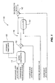
Fig. 1 , a portion of a decoder using smooth reference prediction is indicated generally by thereference numeral 100. - The
decoder portion 100 includes amotion compensator 112 having an output in signal communication with a first non-inverting input of acombiner 132. An output of thecombiner 132 is connected in signal communication with an input of aswitch 142. A first output of theswitch 142 is connected in signal communication with a first non-inverting input of acombiner 162. A second output of theswitch 142 is connected in signal communication with an input of afilter 152. An output of thefilter 152 is connected in signal communication with the first non-inverting input of thecombiner 162. - An output of a
reference frame buffer 122 is connected in signal communication with a first input of themotion compensator 112. - A second input of the
motion compensator 112 is available as an input to thedecoder portion 100, for receiving enhancement layer motion vectors. A third input of themotion compensator 112 is available as an input to thedecoder portion 100, for receiving upsampled base layer motion vectors. A second non-inverting input of thecombiner 132 is available as an input of thedecoder portion 100, for receiving an upsampled base layer residual. A control input of theswitch 142 is available as an input of thedecoder portion 100, for receiving a smoothed_reference_flag syntax element. A second non-inverting input of thecombiner 162 is available as an input of thedecoder portion 100, for receiving an enhancement layer residual. An output of thecombiner 162 is available as an output of thedecoder portion 100, for outputting a reconstructed block R. - However, the preceding prior art techniques disadvantageously cannot be directly used with bit depth scalability.
- The document
US 2005259729 A1 relates to a method for coding a quality scalable video sequence.US 2005259729 A1 teaches decoding a base-layer bitstream to generate a reconstructed 8-bit output frame. The reconstructed 8-bit output frame is then up-scaled, chroma upsampled, and/or color converted to generate an up-scaled N-bit output frame. On the other hand, an enhancement-layer bitstream is decoded to generate N-bit image residual. Based on the up-scaled N-bit output frame and N-bit image residual, an N-bit video output can be generated for the enhancement layer. - The prior art methods disclosed in document
EP-A-1 827 024 , in a scientific article by A. SEGALL and Y. SU ("Inter-layer Prediction for Bit-Depth Scalable Coding" 24RD JVT MEETING, 29 June 2007 (2007-06-29) - 5 August 2007 (2007-08-05)), and SEGALL et al. ("System for bit-depth scalable coding" JOINT VIDEO TEAM (JVT) OF ISO/IEC MPEG & ITU-T VCEG(ISO/IEC JTC1/SC29/WG11 AND ITU-T SG16 Q6), XX, XX, no. JVT-W113, 25 April 2007 (2007-04-25)) and in an article by MARTIN WINKEN ET AL ("Bit-Depth Scalable Video Coding" IMAGE PROCESSING, 2007. ICIP 2007. IEEE INTERNATIONAL CONFERENCE ON, IEEE, PI, 1 September 2007 (2007-09-01), pages 1-5, ISBN: 978-1-4244-1436-9) and in documentUS2005259729 A1 and in an article of Yuwen Wu; Yongying Gao; Ying Chen ("Bit Depth Scalable Coding", International Conference on Multimedia and Expo, 2-5 July 2007 IEEE)) as well as in an article of Gao Y; Segall A; Wiegand T ("Report of AhG on bit depth and chroma format scalability" 23rd JVT meeting; 80th MPEG meeting; 21-04-2007 - 27-04-2007; San Jose CA,US; (Joint Video Team of ISO/IEG JTC1/SC29/WG11 and ITU-T SG.16)) methods are described that all require a reconstructed base layer for decoding the enhancement layer, that is, these references also teach performing motion compensation at the base layer. - These and other drawbacks and disadvantages of the prior art are addressed by the present principles, which are directed to methods and apparatus for inter-layer residue prediction for scalable video according to claims.
- These and other aspects, features and advantages of the present principles will become apparent from the following detailed description of exemplary embodiments, which is to be read in connection with the accompanying drawings.
- The present principles may be better understood in accordance with the following exemplary figures, in which:
-
Fig. 1 is a block diagram for a portion of a decoder using smooth reference prediction, in accordance with the prior art; -
FIG. 2 is a block diagram for an exemplary video encoder to which the present principles may be applied, in accordance with an embodiment of the present principles; -
FIG. 3 is a block diagram for an exemplary decoder to which the present principles may be applied, in accordance with an embodiment of the present principles; -
FIG. 4 is a flow diagram for an exemplary method for encoding using inter-layer residual prediction for bit depth scalability, in accordance with an embodiment of the present principles; and -
FIG. 5 is a flow diagram for an exemplary method for decoding using inter-layer residual prediction for bit depth scalability, in accordance with an embodiment of the present principles. - The present principles are directed to methods and apparatus for inter-layer residue prediction for scalable video.
- The present description illustrates the present principles. It will thus be appreciated that those skilled in the art will be able to devise various arrangements that, although not explicitly described or shown herein, embody the present principles and are included within its spirit and scope.
- All examples and conditional language recited herein are intended for pedagogical purposes to aid the reader in understanding the present principles and the concepts contributed by the inventor(s) to furthering the art, and are to be construed as being without limitation to such specifically recited examples and conditions.
- Moreover, all statements herein reciting principles, aspects, and embodiments of the present principles, as well as specific examples thereof, are intended to encompass both structural and functional equivalents thereof. Additionally, it is intended that such equivalents include both currently known equivalents as well as equivalents developed in the future, i.e., any elements developed that perform the same function, regardless of structure.
- Thus, for example, it will be appreciated by those skilled in the art that the block diagrams presented herein represent conceptual views of illustrative circuitry embodying the present principles. Similarly, it will be appreciated that any flow charts, flow diagrams, state transition diagrams, pseudocode, and the like represent various processes which may be substantially represented in computer readable media and so executed by a computer or processor, whether or not such computer or processor is explicitly shown.
- The functions of the various elements shown in the figures may be provided through the use of dedicated hardware as well as hardware capable of executing software in association with appropriate software. When provided by a processor, the functions may be provided by a single dedicated processor, by a single shared processor, or by a plurality of individual processors, some of which may be shared. Moreover, explicit use of the term "processor" or "controller" should not be construed to refer exclusively to hardware capable of executing software, and may implicitly include, without limitation, digital signal processor ("DSP") hardware, read-only memory ("ROM") for storing software, random access memory ("RAM"), and non-volatile storage.
- Other hardware, conventional and/or custom, may also be included. Similarly, any switches shown in the figures are conceptual only. Their function may be carried out through the operation of program logic, through dedicated logic, through the interaction of program control and dedicated logic, or even manually, the particular technique being selectable by the implementer as more specifically understood from the context.
- In the claims hereof, any element expressed as a means for performing a specified function is intended to encompass any way of performing that function including, for example, a) a combination of circuit elements that performs that function or b) software in any form, including, therefore, firmware, microcode or the like, combined with appropriate circuitry for executing that software to perform the function. The present principles as defined by such claims reside in the fact that the functionalities provided by the various recited means are combined and brought together in the manner which the claims call for. It is thus regarded that any means that can provide those functionalities are equivalent to those shown herein.
- Reference in the specification to "one embodiment" or "an embodiment" of the present principles means that a particular feature, structure, characteristic, and so forth described in connection with the embodiment is included in at least one embodiment of the present principles. Thus, the appearances of the phrase "in one embodiment" or "in an embodiment" appearing in various places throughout the specification are not necessarily all referring to the same embodiment. Moreover, the phrase "in another embodiment" does not exclude the subject matter of the described embodiment from being combined, in whole or in part, with another embodiment.
- It is to be appreciated that the use of the terms "and/or" and "at least one of", for example, in the cases of "A and/or B" and "at least one of A and B", is intended to encompass the selection of the first listed option (A) only, or the selection of the second listed option (B) only, or the selection of both options (A and B). As a further example, in the cases of "A, B, and/or C" and "at least one of A, B, and C", such phrasing is intended to encompass the selection of the first listed option (A) only, or the selection of the second listed option (B) only, or the selection of the third listed option (C) only, or the selection of the first and the second listed options (A and B) only, or the selection of the first and third listed options (A and C) only, or the selection of the second and third listed options (B and C) only, or the selection of all three options (A and B and C). This may be extended, as readily apparent by one of ordinary skill in this and related arts, for as many items listed.
- Moreover, it is to be appreciated that while one or more embodiments of the present principles are described herein with respect to the scalable video coding extension of the MPEG-4 AVC standard, the present principles are not limited to solely this extension and/or this standard and, thus, may be utilized with respect to other video coding standards, recommendations, and extensions thereof, while maintaining the spirit of the present principles.
- Further, it is to be appreciated that while the following description herein uses 10-bit video with respect to one or more examples of high bit video, the present principles are applicable to any number of bits greater than eight including, but not limited to, for example, 12-bit, 14-bit, and so forth.
- As used herein, "high level syntax" refers to syntax present in the bitstream that resides hierarchically above the macroblock layer. For example, high level syntax, as used herein, may refer to, but is not limited to, syntax at the slice header level, Supplemental Enhancement Information (SEI) level, Picture Parameter Set (PPS) level, Sequence Parameter Set (SPS) level and Network Abstraction Layer (NAL) unit header level.
- As noted above, the present principles are directed to methods and apparatus for inter-layer residue prediction for scalable video.
- Turning to
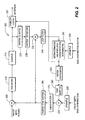
FIG. 2 , an exemplary video encoder to which the present principles may be applied is indicated generally by thereference numeral 200. - The
encoder 200 includes acombiner 205 having an output in signal communication with an input of atransformer 210. An output of thetransformer 210 is connected in signal communication with an input of aquantizer 215. An output of the quantizer is connected in signal communication a first input of anentropy coder 220 and an input of aninverse quantizer 225. An output of theinverse quantizer 225 is connected in signal communication with an input of aninverse transformer 230. An output of theinverse transformer 230 is connected in signal communication with a first non-inverting input of acombiner 235. An output of thecombiner 235 is connected in signal communication with an input of aloop filter 240. An output of theloop filter 240 is connected in signal communication with a first input of a motion estimator andinter-layer prediction determinator 245. An output of the motion estimator andinter-layer prediction determinator 245 is connected in signal communication with a second input of theentropy coder 220 and an input of amotion compensator 255. An output of themotion compensator 255 is connected in signal communication with an input of atone mapper 260. An output of thetone mapper 260 is connected in signal communication with a first non-inverting input of acombiner 270. An output of thecombiner 270 is connected in signal communication with an input of asmooth filter 275. An output of thesmooth filter 275 is connected in signal communication with an input of aninverse tone mapper 280. An output of theinverse tone mapper 280 is connected in signal communication with a second non-inverting input of thecombiner 235 and an inverting input of the combiner 105. An output of anupsampler 250 is connected in signal communication with a second input of the motion estimator andinter-layer prediction determinator 245. An output of anupsampler 265 is connected in signal communication with a second non-inverting input of thecombiner 270. - An input of the
combiner 205 is available as an input of theencoder 200, for receiving high bit depth pictures. An input of theupsampler 250 is available as an input of theencoder 200, for receiving a base layer motion vector. An input of theupsampler 265 is available as an input of theencoder 200, for receiving a low bit depth base layer residual. An output of theentropy coder 220 is available as an output of theencoder 200, for outputting a bitstream. - Turning to
FIG. 3 , an exemplary decoder to which the present principles may be applied is indicated generally by thereference numeral 300. - The
decoder 300 includes anentropy decoder 305 having a first output in signal communication with an input of aninverse quantizer 310. An output of theinverse quantizer 310 is connected in signal communication with an input of aninverse transformer 315. An output of theinverse transformer 315 is connected in signal communication with a first non-inverting input of acombiner 320. - A second output of the
entropy decoder 305 is connected in signal communication with a first input of amotion compensator 325. An output of themotion compensator 325 is connected in signal communication with an input of atone mapper 330. An output of thetone mapper 330 is connected in signal communication with a first non-inverting input of acombiner 335. An output of thecombiner 335 is connected in signal communication with a first input of asmooth filter 340. An output of thesmooth filter 340 is connected in signal communication with an input of aninverse tone mapper 345. An output of theinverse tone mapper 345 is connected in signal communication with a second non-inverting input of thecombiner 320. - An output of an
upsampler 350 is connected in signal communication with a second non-inverting input of thecombiner 335. An output of anupsampler 355 is connected in signal communication with a second input of themotion compensator 325. - An input of the
entropy decoder 305 is available as an input to thedecoder 300, for receiving an enhancement layer bitstream. A third input of themotion compensator 325 is available as an input of thedecoder 300, for receiving multiple enhancement layer reference frames. A second input of thesmooth reference filter 340 is available as an input to thedecoder 300, for receiving a smooth reference flag. An input of theupsampler 350 is available as an input to thedecoder 300, for receiving a low bit depth base layer residual. An input of theupsampler 355 is available as an input to thedecoder 300, for receiving a base layer motion vector. An output of thecombiner 320 is available as an output of thedecoder 300, for outputting pictures. - Bit-depth scalability is potentially useful in consideration of the fact that at some point in the future, conventional 8-bit depth and high bit depth digital imaging systems will simultaneously exist in marketplaces.
- In accordance with one or more embodiments of the present principles, new techniques are proposed for inter-layer residue prediction for bit depth scalability (BDS).
- In bit depth scalability, if single loop decoding is used, when motion compensation is performed at the enhancement layer (higher bit depth layer), it is difficult to apply inverse tone mapping for inter-layer residue prediction. Thus, in accordance with the present principles, we present new inter-layer residue prediction techniques to improve the coding efficiency of bit depth scalability. In accordance with one or more embodiments of the present principles, instead of doing inverse tone mapping for inter-layer residue prediction in the residue domain, we convert the inverse tone mapping problem from the residue domain to the pixel domain (spatial domain) for inter-layer residue prediction.
- For illustrative purposes, one or more examples are provided herein which consider only bit-depth and the use of a single loop decoding architecture. However, it is to be appreciated that, given the teachings of the present principles provided herein, such principles as described with respect to the above reference examples may be readily extended by one of ordinary skill in this and related arts to combined scalability including, but not limited to, for example, bit-depth and spatial scalability, and so forth. In addition, the present principles may be readily applied in multiple loop decoding architecture. Of course, the present principles are not limited to the preceding applications and variations and, thus, other applications and variations, as readily determined by one of ordinary skill in this and related arts may also be employed with respect to the present principles while maintaining the spirit of the present principles.
- Thus, in an embodiment, if inter-layer residue prediction is used, inverse tone mapping is applied after we add tone mapped motion compensated prediction and upsampled residue from the base layer. For bit depth scalability only, the spatial upsampling factor is 1.
- Correspondingly, one example of an encoding method in accordance with an embodiment is as follows:
- 1. The prediction block P is obtained using the enhancement layer reference frames and then P is tone mapping into base layer, we get T(P);
- 2. The corresponding base layer residual block rb is spatially upsampled and U(rb ) is added to P to form T(P)+U(rb );
- 3. A filter is used, to obtain S(T(P) + U(rb ));
- 4. Inverse tone mapping is then applied, to obtain T -1(S(T(P) + U(rb ))) ; and
- 5. The enhancement layer residual block re is generated by subtract (4) from enhancement layer block O, re = O - T -1(S(T(P) + U(rb ))).
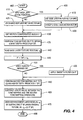
- Turning to
FIG. 4 , an exemplary method for encoding using inter-layer residual prediction for bit depth scalability is indicated generally by thereference numeral 400. - The
method 400 includes astart block 405 that passes control to adecision block 410. Thedecision block 410 determines whether or not to apply inter-layer motion prediction. If so, then control is passed to afunction block 415. Otherwise, control is passed to afunction block 425. - The
function block 415 use a base layer motion vector, and passes control to afunction block 420. Thefunction block 420 upsamples the base layer motion vector, and passes control to afunction block 430. - The
function block 425 uses an enhancement layer motion vector, and passes control to thefunction block 430. - The
function block 430 gets the motion compensated block P, and passes control to afunction block 435. Thefunction block 435 performs tone mapping on P to obtain a low bit depth T(P), and passes control to afunction block 440. Thefunction block 440 reads the base layer texture residual rb, and passes control to afunction block 445. Thefunction block 445 calculates P' = T(P) + rb, and passes control to adecision block 450. Thedecision block 450 determines whether or not to apply a smooth reference. If so, the control is passed to afunction block 455. Otherwise, control is passed to afunction block 460. - The
function block 455 applies the smooth filer on P', and passes control to afunction block 460. - The
function block 460 performs inverse tone mapping on P' to obtain a high bit depth prediction T-1(P'), and passes control to afunction block 465. Thefunction block 465 subtracts an error value, between the tone mapping and the inverse tone mapping operations, from the high bit depth prediction T-1(P'), and passes control to afunction block 470. Thefunction block 470 obtains the enhancement layer residual re by subtracting T-1(P') from the original picture, where re = O - T-1(P'), with O representing the original picture, and passes control to anend block 499. - One example of a decoding method in accordance with an embodiment is as follows:
- 1. The prediction block P is obtained using the enhancement layer reference frames and then P is tone mapping into base layer, we get T(P);
- 2. The corresponding base layer residual block rb is spatially upsampled and U(rb ) is added to P to form T(P) + U(rb );
- 3. A filter is used, to obtain S(T(P) + U(rb ));
- 4. Inverse tone mapping is then applied, to obtain T -1(S(T(P) + U(rb ))); and
- 5. The enhancement layer residual block is added to (4) to obtain the reconstruction block R = T -1(S(T(P) + U(rb ))) + re
- Turning to
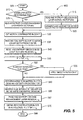
FIG. 5 , an exemplary method for decoding using inter-layer residual prediction for bit depth scalability is indicated generally by thereference numeral 500. - The
method 500 includes astart block 505 that passes control to adecision block 510. Thedecision block 510 determines whether or not an inter-layer motion prediction flag is set to true. If so, then control is passed to afunction block 515. Otherwise, control is passed to afunction block 525. - The
function block 515 reads and entropy decodes a base layer motion vector, and passes control to afunction block 520. Thefunction block 520 upsamples the base layer motion vector, and passes control to afunction block 530. - The
function block 525 reads and entropy decodes an enhancement layer motion vector, and passes control to thefunction block 530. - The
function block 530 gets the motion compensated block P, and passes control to afunction block 535. Thefunction block 535 performs tone mapping on P to obtain a low bit depth T(P), and passes control to afunction block 540. Thefunction block 540 reads and entropy decodes the base layer texture residual rb, and passes control to afunction block 545. Thefunction block 545 calculates P' = T(P) + rb, and passes control to adecision block 550. Thedecision block 550 determines whether or not a smooth reference flag is set to true. If so, the control is passed to afunction block 555. Otherwise, control is passed to afunction block 560. - The
function block 555 applies the smooth filer on P', and passes control to afunction block 560. - The
function block 560 performs inverse tone mapping on P' to obtain a high bit depth prediction T-1(P'), and passes control to afunction block 565. Thefunction block 565 adds an error value, between the tone mapping and the inverse tone mapping, to the high bit depth prediction T-1(P'), and passes control to afunction block 567. Thefunction block 567 reads and entropy decodes the enhancement layer residual re, and passes control to afunction block 570. Thefunction block 570 obtains the reconstruction block R, where R = T-1(P') +re, and passes control to anend block 599. - It has been noted in the prior art that the motion compensated block P can be generated by a motion vector from the enhancement layer if inter-layer motion prediction is not used, or from an upsampled motion vector from the base layer if inter-layer motion prediction is used. In an embodiment of the present principles, we allow our techniques to be used for both cases. In another embodiment, our techniques can only be combined when inter-layer motion prediction is used. If inter-layer motion prediction is not used, bit shift is applied for residue prediction, as in the above references third and fourth prior art approaches.
- Also, the schemes of the third and fourth prior art approaches can be switched. That is, we can first perform filtering then inverse tone mapping. Alternatively, we can first perform inverse tone mapping, then perform filtering. The filter can be linear, or nonlinear, one dimensional, or two dimensional, and so forth. In one example, we can use 3 tap filter [1 2 1], first vertically, then horizontally. The filter can also be identical, such that the third prior art procedure is not required.
- Thus, in accordance with one embodiment of the present principles, we signal both tone mapping and inverse tone mapping method. The signaling may be performed using an algorithm calculation, a look up table, and/or so forth. The signaling may be performed at the sequence, picture, slice, or block level. Since tone mapping and inverse tone mapping are not truly invertible, i.e., T -1(T) ≠ I, we can take the error I - T -1(T) into consideration, where l means identity. In one example, since T -1(T(P)) ≠ P, we can take the error d = P - T -1(T(P)) into consideration. That is, at the encoder, we substract d. At the decoder, we add d.
- A description will now be given of some of the many attendant advantages/features of the present invention, some of which have been mentioned above. For example, one advantage/feature is an apparatus having an encoder for encoding a block of a picture by applying inverse tone mapping to an inter-layer residue prediction process for the block. The inverse tone mapping is performed in the pixel domain to support bit depth scalability.
- Another advantage/feature is the apparatus having the encoder as described above, wherein the encoder performs the inter-layer residue prediction process by performing motion compensation in an enhancement layer of the picture to obtain an enhancement layer prediction, performing tone mapping on the enhancement layer prediction into a base layer of the picture to obtain a tone mapped motion compensated low bit depth prediction for the block, adding a spatially upsampled residue from the base layer to the tone mapped motion compensated low bit depth prediction for the block to obtain a sum, and performing the inverse tone mapping on the sum into the enhancement layer to obtain a higher bit depth prediction for the block.
- Yet another advantage/feature is the apparatus having the encoder as described above, wherein the encoder further performs the inter-layer residue prediction process by applying a smoothing filter to the sum prior to performing the inverse tone mapping. The inverse tone mapping is performed on the filtered sum.
- Still another advantage/feature is the apparatus having the encoder as described above, wherein at least one of a high level syntax element and a block level syntax element is used to signal any of the tone mapping and the inverse tone mapping.
- Moreover, another advantage/feature is the apparatus having the encoder as described above, wherein the high level syntax element is comprised in at least one of a slice header, a sequence parameter set, a picture parameter set, a view parameter set, a network abstraction layer unit header, and a supplemental enhancement information message.
- Further, another advantage/feature is the apparatus having the encoder as described above, wherein the encoder further performs the inter-layer residue prediction process by subtracting an error value, between the tone mapping and the inverse tone mapping, from the higher bit depth prediction for the block.
- These and other features and advantages of the present principles may be readily ascertained by one of ordinary skill in the pertinent art based on the teachings herein. It is to be understood that the teachings of the present principles may be implemented in various forms of hardware, software, firmware, special purpose processors, or combinations thereof.
- Most preferably, the teachings of the present principles are implemented as a combination of hardware and software. Moreover, the software may be implemented as an application program tangibly embodied on a program storage unit. The application program may be uploaded to, and executed by, a machine comprising any suitable architecture. Preferably, the machine is implemented on a computer platform having hardware such as one or more central processing units ("CPU"), a random access memory ("RAM"), and input/output ("I/O") interfaces. The computer platform may also include an operating system and microinstruction code. The various processes and functions described herein may be either part of the microinstruction code or part of the application program, or any combination thereof, which may be executed by a CPU. In addition, various other peripheral units may be connected to the computer platform such as an additional data storage unit and a printing unit.
- It is to be further understood that, because some of the constituent system components and methods depicted in the accompanying drawings are preferably implemented in software, the actual connections between the system components or the process function blocks may differ depending upon the manner in which the present principles are programmed. Given the teachings herein, one of ordinary skill in the pertinent art will be able to contemplate these and similar implementations or configurations of the present principles.
Claims (12)
- An apparatus, comprising:a decoder (300) for decoding a block of a picture by applying inverse tone mapping to an inter layer residue prediction process for the block wherein the inverse tone mapping is performed in the pixel domain,wherein the decoder includes:a motion compensator (325);a tone mapper (330) coupled to said motion compensator;a combiner (335) coupled to said tone mapper;a spatial upsampler (350) coupled to said combiner;an inverse tone mapper (345) coupled to said combiner, andwherein said motion compensator (325) performs motion compensation in an enhancement layer of the picture to obtain a motion compensated prediction for the enhancement layer, said tone mapper (330) performs tone mapping on the motion compensated prediction for the enhancement layer to obtain a tone mapped motion compensated low bit depth prediction for the block, said combiner (335) adds a spatially upsampled residue from the base layer to the tone mapped motion compensated low bit depth prediction for the block to obtain a sum, and said inverse tone mapper (345) performs the inverse tone mapping on the sum to obtain a higher bit depth prediction for the block.
- The apparatus of claim 1, further comprising a smooth filter (340) coupled to said combiner and said inverse tone mapper, said smooth filter applying a smoothing filtering to the sum prior to performing the inverse tone mapping, and wherein the inverse tone mapping is performed on the filtered sum.
- The apparatus of claim 1, wherein at least one of a high level syntax element and a block level syntax element is used to signal any of the tone mapping and the inverse tone mapping.
- The apparatus of claim 3, wherein the high level syntax element is comprised in at least one of a slice header, a sequence parameter set, a picture parameter set, a view parameter set, a network abstraction layer unit header, and a supplemental enhancement information message.
- The apparatus of claim 1, wherein said decoder (300) adds an error value, between signal values obtained from the tone mapping and the inverse tone mapping, to the higher bit depth prediction for the block.
- The apparatus of claim 1 wherein the inverse tone mapping is performed in the pixel domain to support bit depth scalability.
- A method, comprising:decoding a block of a picture by applying inverse tone mapping to an inter layer residue prediction process for the block, wherein the inverse tone mapping is performed in the pixel domain (540, 560) wherein the decoding step comprises:performing motion compensation in an enhancement layer of the picture to obtain a motion compensated prediction for the enhancement layer (530);performing tone mapping on the motion compensated prediction for the enhancement layer to obtain a tone mapped motion compensated low bit depth prediction for the block (535);adding a spatially upsampled residue from the base layer to the tone mapped motion compensated low bit depth prediction for the block to obtain a sum (540, 545); andperforming the inverse tone mapping on the sum to obtain a higher bit depth prediction for the block (560).
- The method of claim 7, wherein the decoding step further comprises applying a smoothing filter to the sum prior to said step of performing the inverse tone mapping, and wherein the inverse tone mapping is performed on the filtered sum (555).
- The method of claim 7, wherein at least one of a high level syntax element and a block level syntax element is used to signal any of the tone mapping and the inverse tone mapping.
- The method of claim 9, wherein the high level syntax element is comprised in at least one of a slice header, a sequence parameter set, a picture parameter set, a view parameter set, a network abstraction layer unit header, and a supplemental enhancement information message.
- The method of claim 7, wherein an error value, between signal values obtained from the tone mapping and the inverse tone mapping, is added to the higher bit depth prediction for the block (565).
- The method of claim 7 wherein the inverse tone mapping is performed in the pixel domain to support bit depth scalability.
Applications Claiming Priority (2)
| Application Number | Priority Date | Filing Date | Title |
|---|---|---|---|
| US97995607P | 2007-10-15 | 2007-10-15 | |
| PCT/US2008/011710 WO2009051692A2 (en) | 2007-10-15 | 2008-10-14 | Methods and apparatus for inter-layer residue prediction for scalable video |
Publications (2)
| Publication Number | Publication Date |
|---|---|
| EP2206349A2 EP2206349A2 (en) | 2010-07-14 |
| EP2206349B1 true EP2206349B1 (en) | 2015-03-11 |
Family
ID=40493616
Family Applications (2)
| Application Number | Title | Priority Date | Filing Date |
|---|---|---|---|
| EP08839103.2A Active EP2206349B1 (en) | 2007-10-15 | 2008-10-14 | Methods and apparatus for inter-layer residue prediction for scalable video |
| EP08839433.3A Active EP2206350B1 (en) | 2007-10-15 | 2008-10-14 | Methods and apparatus for inter-layer residue prediction for scalable video |
Family Applications After (1)
| Application Number | Title | Priority Date | Filing Date |
|---|---|---|---|
| EP08839433.3A Active EP2206350B1 (en) | 2007-10-15 | 2008-10-14 | Methods and apparatus for inter-layer residue prediction for scalable video |
Country Status (8)
| Country | Link |
|---|---|
| US (2) | US8385412B2 (en) |
| EP (2) | EP2206349B1 (en) |
| JP (2) | JP5534521B2 (en) |
| KR (2) | KR101436671B1 (en) |
| CN (2) | CN101822055B (en) |
| BR (2) | BRPI0817769A2 (en) |
| TW (2) | TWI528831B (en) |
| WO (2) | WO2009051694A2 (en) |
Families Citing this family (34)
| Publication number | Priority date | Publication date | Assignee | Title |
|---|---|---|---|---|
| US8184693B2 (en) * | 2008-04-11 | 2012-05-22 | Intel Corporation | Adaptive filtering for bit-depth scalable video codec |
| DK2835976T3 (en) * | 2008-04-16 | 2016-12-05 | Ge Video Compression Llc | Bit depth scalability |
| CN102308579B (en) * | 2009-02-03 | 2017-06-06 | 汤姆森特许公司 | The method and apparatus of the motion compensation of the gradable middle use smooth reference frame of locating depth |
| BRPI1008372A2 (en) | 2009-02-11 | 2018-03-06 | Thomson Licensing | methods and apparatus for bit depth scalable video encoding and decoding using tone mapping and reverse tone mapping |
| KR101346008B1 (en) * | 2009-03-13 | 2013-12-31 | 돌비 레버러토리즈 라이쎈싱 코오포레이션 | Layered compression of high dynamic range, visual dynamic range, and wide color gamut video |
| JP5237212B2 (en) * | 2009-07-09 | 2013-07-17 | キヤノン株式会社 | Image processing apparatus and image processing method |
| US20110134315A1 (en) * | 2009-12-08 | 2011-06-09 | Avi Levy | Bi-Directional, Local and Global Motion Estimation Based Frame Rate Conversion |
| CN103563372B (en) | 2011-04-14 | 2017-05-24 | 杜比实验室特许公司 | Multiple color channel multiple regression predictor |
| EP2702764B1 (en) | 2011-04-25 | 2016-08-31 | Dolby Laboratories Licensing Corporation | Non-linear vdr residual quantizer |
| US8891863B2 (en) * | 2011-06-13 | 2014-11-18 | Dolby Laboratories Licensing Corporation | High dynamic range, backwards-compatible, digital cinema |
| WO2013081615A1 (en) * | 2011-12-01 | 2013-06-06 | Intel Corporation | Motion estimation methods for residual prediction |
| TWI556629B (en) | 2012-01-03 | 2016-11-01 | 杜比實驗室特許公司 | Specifying visual dynamic range coding operations and parameters |
| WO2013162450A1 (en) * | 2012-04-24 | 2013-10-31 | Telefonaktiebolaget L M Ericsson (Publ) | Encoding and deriving parameters for coded multi-layer video sequences |
| US9219913B2 (en) | 2012-06-13 | 2015-12-22 | Qualcomm Incorporated | Inferred base layer block for TEXTURE—BL mode in HEVC based single loop scalable video coding |
| CN104322068A (en) * | 2012-06-27 | 2015-01-28 | 英特尔公司 | Cross-layer cross-channel residual prediction |
| KR20150029745A (en) | 2012-07-09 | 2015-03-18 | 브이아이디 스케일, 인크. | Codec architecture for multiple layer video coding |
| US9516309B2 (en) | 2012-07-09 | 2016-12-06 | Qualcomm Incorporated | Adaptive difference domain spatial and temporal reference reconstruction and smoothing |
| US9277212B2 (en) * | 2012-07-09 | 2016-03-01 | Qualcomm Incorporated | Intra mode extensions for difference domain intra prediction |
| CA2807404C (en) * | 2012-09-04 | 2017-04-04 | Research In Motion Limited | Methods and devices for inter-layer prediction in scalable video compression |
| US20140086319A1 (en) * | 2012-09-25 | 2014-03-27 | Sony Corporation | Video coding system with adaptive upsampling and method of operation thereof |
| US10085017B2 (en) * | 2012-11-29 | 2018-09-25 | Advanced Micro Devices, Inc. | Bandwidth saving architecture for scalable video coding spatial mode |
| BR112015013203A2 (en) * | 2012-12-13 | 2017-07-11 | Sony Corp | transmission and reception devices and methods |
| CN116708768A (en) * | 2013-01-04 | 2023-09-05 | Ge视频压缩有限责任公司 | Efficient scalable coding concept |
| US20140192880A1 (en) * | 2013-01-04 | 2014-07-10 | Zhipin Deng | Inter layer motion data inheritance |
| US10045041B2 (en) | 2013-04-05 | 2018-08-07 | Intel Corporation | Techniques for inter-layer residual prediction |
| KR101773413B1 (en) | 2013-04-08 | 2017-08-31 | 지이 비디오 컴프레션, 엘엘씨 | Coding concept allowing efficient multi-view/layer coding |
| EP3000097A1 (en) * | 2013-05-23 | 2016-03-30 | Thomson Licensing | Method for tone-mapping a video sequence |
| US9497473B2 (en) * | 2013-10-03 | 2016-11-15 | Qualcomm Incorporated | High precision explicit weighted prediction for video coding |
| CN105850126B (en) | 2013-12-24 | 2019-03-26 | 株式会社Kt | Method and apparatus for being encoded/decoded to multi-layer video signal |
| CN111314694B (en) * | 2013-12-27 | 2023-05-05 | 索尼公司 | Image processing apparatus and method |
| US10708606B2 (en) | 2014-03-24 | 2020-07-07 | Kt Corporation | Multilayer video signal encoding/decoding method and device |
| WO2016054076A1 (en) * | 2014-10-02 | 2016-04-07 | Dolby Laboratories Licensing Corporation | Dual-ended metadata for judder visibility control |
| EP3076669A1 (en) * | 2015-04-03 | 2016-10-05 | Thomson Licensing | Method and apparatus for generating color mapping parameters for video encoding |
| WO2023072216A1 (en) * | 2021-10-28 | 2023-05-04 | Beijing Bytedance Network Technology Co., Ltd. | Method, apparatus, and medium for video processing |
Citations (1)
| Publication number | Priority date | Publication date | Assignee | Title |
|---|---|---|---|---|
| US20050259729A1 (en) * | 2004-05-21 | 2005-11-24 | Shijun Sun | Video coding with quality scalability |
Family Cites Families (8)
| Publication number | Priority date | Publication date | Assignee | Title |
|---|---|---|---|---|
| AU2003278445A1 (en) * | 2002-11-13 | 2004-06-03 | Koninklijke Philips Electronics N.V. | Transmission system with colour depth scalability |
| US7295345B2 (en) * | 2003-04-29 | 2007-11-13 | Eastman Kodak Company | Method for calibration independent defect correction in an imaging system |
| US8218625B2 (en) * | 2004-04-23 | 2012-07-10 | Dolby Laboratories Licensing Corporation | Encoding, decoding and representing high dynamic range images |
| US7483486B2 (en) * | 2004-07-02 | 2009-01-27 | Max-Planck-Gesellschaft Zur Forderung Der Wissenschaften E.V. | Method and apparatus for encoding high dynamic range video |
| DE102004059993B4 (en) | 2004-10-15 | 2006-08-31 | Fraunhofer-Gesellschaft zur Förderung der angewandten Forschung e.V. | Apparatus and method for generating a coded video sequence using interlayer motion data prediction, and computer program and computer readable medium |
| US7876833B2 (en) * | 2005-04-11 | 2011-01-25 | Sharp Laboratories Of America, Inc. | Method and apparatus for adaptive up-scaling for spatially scalable coding |
| US8483277B2 (en) * | 2005-07-15 | 2013-07-09 | Utc Fire & Security Americas Corporation, Inc. | Method and apparatus for motion compensated temporal filtering using split update process |
| US8014445B2 (en) * | 2006-02-24 | 2011-09-06 | Sharp Laboratories Of America, Inc. | Methods and systems for high dynamic range video coding |
-
2008
- 2008-10-14 WO PCT/US2008/011712 patent/WO2009051694A2/en active Application Filing
- 2008-10-14 CN CN2008801108139A patent/CN101822055B/en active Active
- 2008-10-14 EP EP08839103.2A patent/EP2206349B1/en active Active
- 2008-10-14 JP JP2010529929A patent/JP5534521B2/en active Active
- 2008-10-14 BR BRPI0817769-4A patent/BRPI0817769A2/en not_active Application Discontinuation
- 2008-10-14 US US12/734,175 patent/US8385412B2/en active Active
- 2008-10-14 KR KR1020107008155A patent/KR101436671B1/en active IP Right Grant
- 2008-10-14 KR KR1020107010670A patent/KR101492302B1/en active IP Right Grant
- 2008-10-14 JP JP2010529930A patent/JP5534522B2/en active Active
- 2008-10-14 EP EP08839433.3A patent/EP2206350B1/en active Active
- 2008-10-14 BR BRPI0818648-0A patent/BRPI0818648A2/en not_active Application Discontinuation
- 2008-10-14 WO PCT/US2008/011710 patent/WO2009051692A2/en active Application Filing
- 2008-10-14 CN CN2008801115895A patent/CN101822059B/en active Active
- 2008-10-14 US US12/734,173 patent/US8537894B2/en active Active
- 2008-10-15 TW TW097139609A patent/TWI528831B/en active
- 2008-10-15 TW TW097139607A patent/TWI422231B/en active
Patent Citations (1)
| Publication number | Priority date | Publication date | Assignee | Title |
|---|---|---|---|---|
| US20050259729A1 (en) * | 2004-05-21 | 2005-11-24 | Shijun Sun | Video coding with quality scalability |
Non-Patent Citations (2)
| Title |
|---|
| GAO Y ET AL: "AHG Report: SVC bit depth and chroma format", JVT MEETING; MPEG MEETING; 21-04-2007 - 27-04-2007; SAN JOSÃ CR ,US; (JOINT VIDEO TEAM OF ISO/IEC JTC1/SC29/WG11 AND ITU-T SG.16 ), no. JVT-W010, 2 May 2007 (2007-05-02), XP030006975, ISSN: 0000-0155 * |
| YUWEN WU ET AL: "Bit Depth Scalable Coding", MULTIMEDIA AND EXPO, 2007 IEEE INTERNATIONAL CONFERENCE ON, IEEE, PI, 1 July 2007 (2007-07-01), pages 1139 - 1142, XP031123831, ISBN: 978-1-4244-1016-3 * |
Also Published As
| Publication number | Publication date |
|---|---|
| JP2011501564A (en) | 2011-01-06 |
| US8537894B2 (en) | 2013-09-17 |
| JP5534521B2 (en) | 2014-07-02 |
| US8385412B2 (en) | 2013-02-26 |
| US20100208809A1 (en) | 2010-08-19 |
| EP2206350B1 (en) | 2015-03-04 |
| CN101822055B (en) | 2013-03-13 |
| WO2009051694A3 (en) | 2009-06-04 |
| CN101822059B (en) | 2012-11-28 |
| US20100208810A1 (en) | 2010-08-19 |
| WO2009051692A3 (en) | 2009-06-04 |
| KR101436671B1 (en) | 2014-09-02 |
| JP2011501563A (en) | 2011-01-06 |
| KR101492302B1 (en) | 2015-02-23 |
| BRPI0817769A2 (en) | 2015-03-24 |
| EP2206350A2 (en) | 2010-07-14 |
| TW200935914A (en) | 2009-08-16 |
| TW200935913A (en) | 2009-08-16 |
| CN101822055A (en) | 2010-09-01 |
| TWI422231B (en) | 2014-01-01 |
| BRPI0818648A2 (en) | 2015-04-07 |
| WO2009051694A2 (en) | 2009-04-23 |
| TWI528831B (en) | 2016-04-01 |
| JP5534522B2 (en) | 2014-07-02 |
| KR20100081988A (en) | 2010-07-15 |
| KR20100085106A (en) | 2010-07-28 |
| WO2009051692A2 (en) | 2009-04-23 |
| EP2206349A2 (en) | 2010-07-14 |
| CN101822059A (en) | 2010-09-01 |
Similar Documents
| Publication | Publication Date | Title |
|---|---|---|
| EP2206349B1 (en) | Methods and apparatus for inter-layer residue prediction for scalable video | |
| US8369422B2 (en) | Methods and apparatus for artifact removal for bit depth scalability | |
| US8867618B2 (en) | Method and apparatus for weighted prediction for scalable video coding | |
| US8867616B2 (en) | Methods and apparatus for bit depth scalable video encoding and decoding utilizing tone mapping and inverse tone mapping | |
| US9681142B2 (en) | Methods and apparatus for motion compensation with smooth reference frame in bit depth scalability | |
| US8737474B2 (en) | Method and apparatus for encoding and/or decoding video data using enhancement layer residual prediction for bit depth scalability | |
| JP5864654B2 (en) | Method and apparatus for video coding and decoding using reduced bit depth update mode and reduced chromaticity sampling update mode | |
| TWI774246B (en) | Derivation of a value for each layer representation of a video bitstream |
Legal Events
| Date | Code | Title | Description |
|---|---|---|---|
| PUAI | Public reference made under article 153(3) epc to a published international application that has entered the european phase |
Free format text: ORIGINAL CODE: 0009012 |
|
| 17P | Request for examination filed |
Effective date: 20100422 |
|
| AK | Designated contracting states |
Kind code of ref document: A2 Designated state(s): AT BE BG CH CY CZ DE DK EE ES FI FR GB GR HR HU IE IS IT LI LT LU LV MC MT NL NO PL PT RO SE SI SK TR |
|
| AX | Request for extension of the european patent |
Extension state: AL BA MK RS |
|
| RIN1 | Information on inventor provided before grant (corrected) |
Inventor name: WU, YU, WEN Inventor name: GAO, YONG, YING Inventor name: LUO, JIANCONG Inventor name: YIN, PENG |
|
| DAX | Request for extension of the european patent (deleted) | ||
| 17Q | First examination report despatched |
Effective date: 20120809 |
|
| REG | Reference to a national code |
Ref country code: DE Ref legal event code: R079 Ref document number: 602008037127 Country of ref document: DE Free format text: PREVIOUS MAIN CLASS: H04N0007260000 Ipc: H04N0019300000 |
|
| RIC1 | Information provided on ipc code assigned before grant |
Ipc: H04N 19/59 20140101ALI20140909BHEP Ipc: H04N 19/70 20140101ALI20140909BHEP Ipc: H04N 19/187 20140101ALI20140909BHEP Ipc: H04N 19/30 20140101AFI20140909BHEP Ipc: H04N 19/61 20140101ALI20140909BHEP Ipc: H04N 19/186 20140101ALI20140909BHEP Ipc: H04N 19/00 20140101ALI20140909BHEP Ipc: H04N 19/184 20140101ALI20140909BHEP |
|
| GRAP | Despatch of communication of intention to grant a patent |
Free format text: ORIGINAL CODE: EPIDOSNIGR1 |
|
| INTG | Intention to grant announced |
Effective date: 20141017 |
|
| GRAS | Grant fee paid |
Free format text: ORIGINAL CODE: EPIDOSNIGR3 |
|
| GRAA | (expected) grant |
Free format text: ORIGINAL CODE: 0009210 |
|
| AK | Designated contracting states |
Kind code of ref document: B1 Designated state(s): AT BE BG CH CY CZ DE DK EE ES FI FR GB GR HR HU IE IS IT LI LT LU LV MC MT NL NO PL PT RO SE SI SK TR |
|
| REG | Reference to a national code |
Ref country code: GB Ref legal event code: FG4D |
|
| REG | Reference to a national code |
Ref country code: CH Ref legal event code: EP |
|
| REG | Reference to a national code |
Ref country code: DE Ref legal event code: R084 Ref document number: 602008037127 Country of ref document: DE |
|
| REG | Reference to a national code |
Ref country code: IE Ref legal event code: FG4D |
|
| REG | Reference to a national code |
Ref country code: AT Ref legal event code: REF Ref document number: 715876 Country of ref document: AT Kind code of ref document: T Effective date: 20150415 |
|
| REG | Reference to a national code |
Ref country code: DE Ref legal event code: R096 Ref document number: 602008037127 Country of ref document: DE Effective date: 20150423 |
|
| REG | Reference to a national code |
Ref country code: DE Ref legal event code: R084 Ref document number: 602008037127 Country of ref document: DE Effective date: 20150327 |
|
| REG | Reference to a national code |
Ref country code: NL Ref legal event code: VDEP Effective date: 20150311 |
|
| REG | Reference to a national code |
Ref country code: NL Ref legal event code: VDEP Effective date: 20150311 |
|
| PG25 | Lapsed in a contracting state [announced via postgrant information from national office to epo] |
Ref country code: FI Free format text: LAPSE BECAUSE OF FAILURE TO SUBMIT A TRANSLATION OF THE DESCRIPTION OR TO PAY THE FEE WITHIN THE PRESCRIBED TIME-LIMIT Effective date: 20150311 Ref country code: SE Free format text: LAPSE BECAUSE OF FAILURE TO SUBMIT A TRANSLATION OF THE DESCRIPTION OR TO PAY THE FEE WITHIN THE PRESCRIBED TIME-LIMIT Effective date: 20150311 Ref country code: LT Free format text: LAPSE BECAUSE OF FAILURE TO SUBMIT A TRANSLATION OF THE DESCRIPTION OR TO PAY THE FEE WITHIN THE PRESCRIBED TIME-LIMIT Effective date: 20150311 Ref country code: NO Free format text: LAPSE BECAUSE OF FAILURE TO SUBMIT A TRANSLATION OF THE DESCRIPTION OR TO PAY THE FEE WITHIN THE PRESCRIBED TIME-LIMIT Effective date: 20150611 Ref country code: ES Free format text: LAPSE BECAUSE OF FAILURE TO SUBMIT A TRANSLATION OF THE DESCRIPTION OR TO PAY THE FEE WITHIN THE PRESCRIBED TIME-LIMIT Effective date: 20150311 Ref country code: HR Free format text: LAPSE BECAUSE OF FAILURE TO SUBMIT A TRANSLATION OF THE DESCRIPTION OR TO PAY THE FEE WITHIN THE PRESCRIBED TIME-LIMIT Effective date: 20150311 |
|
| REG | Reference to a national code |
Ref country code: AT Ref legal event code: MK05 Ref document number: 715876 Country of ref document: AT Kind code of ref document: T Effective date: 20150311 |
|
| REG | Reference to a national code |
Ref country code: LT Ref legal event code: MG4D |
|
| PG25 | Lapsed in a contracting state [announced via postgrant information from national office to epo] |
Ref country code: LV Free format text: LAPSE BECAUSE OF FAILURE TO SUBMIT A TRANSLATION OF THE DESCRIPTION OR TO PAY THE FEE WITHIN THE PRESCRIBED TIME-LIMIT Effective date: 20150311 Ref country code: GR Free format text: LAPSE BECAUSE OF FAILURE TO SUBMIT A TRANSLATION OF THE DESCRIPTION OR TO PAY THE FEE WITHIN THE PRESCRIBED TIME-LIMIT Effective date: 20150612 |
|
| PG25 | Lapsed in a contracting state [announced via postgrant information from national office to epo] |
Ref country code: NL Free format text: LAPSE BECAUSE OF FAILURE TO SUBMIT A TRANSLATION OF THE DESCRIPTION OR TO PAY THE FEE WITHIN THE PRESCRIBED TIME-LIMIT Effective date: 20150311 |
|
| REG | Reference to a national code |
Ref country code: FR Ref legal event code: PLFP Year of fee payment: 8 |
|
| PG25 | Lapsed in a contracting state [announced via postgrant information from national office to epo] |
Ref country code: SK Free format text: LAPSE BECAUSE OF FAILURE TO SUBMIT A TRANSLATION OF THE DESCRIPTION OR TO PAY THE FEE WITHIN THE PRESCRIBED TIME-LIMIT Effective date: 20150311 Ref country code: RO Free format text: LAPSE BECAUSE OF FAILURE TO SUBMIT A TRANSLATION OF THE DESCRIPTION OR TO PAY THE FEE WITHIN THE PRESCRIBED TIME-LIMIT Effective date: 20150311 Ref country code: CZ Free format text: LAPSE BECAUSE OF FAILURE TO SUBMIT A TRANSLATION OF THE DESCRIPTION OR TO PAY THE FEE WITHIN THE PRESCRIBED TIME-LIMIT Effective date: 20150311 Ref country code: PT Free format text: LAPSE BECAUSE OF FAILURE TO SUBMIT A TRANSLATION OF THE DESCRIPTION OR TO PAY THE FEE WITHIN THE PRESCRIBED TIME-LIMIT Effective date: 20150713 Ref country code: EE Free format text: LAPSE BECAUSE OF FAILURE TO SUBMIT A TRANSLATION OF THE DESCRIPTION OR TO PAY THE FEE WITHIN THE PRESCRIBED TIME-LIMIT Effective date: 20150311 |
|
| PG25 | Lapsed in a contracting state [announced via postgrant information from national office to epo] |
Ref country code: IS Free format text: LAPSE BECAUSE OF FAILURE TO SUBMIT A TRANSLATION OF THE DESCRIPTION OR TO PAY THE FEE WITHIN THE PRESCRIBED TIME-LIMIT Effective date: 20150711 Ref country code: PL Free format text: LAPSE BECAUSE OF FAILURE TO SUBMIT A TRANSLATION OF THE DESCRIPTION OR TO PAY THE FEE WITHIN THE PRESCRIBED TIME-LIMIT Effective date: 20150311 Ref country code: AT Free format text: LAPSE BECAUSE OF FAILURE TO SUBMIT A TRANSLATION OF THE DESCRIPTION OR TO PAY THE FEE WITHIN THE PRESCRIBED TIME-LIMIT Effective date: 20150311 |
|
| REG | Reference to a national code |
Ref country code: DE Ref legal event code: R097 Ref document number: 602008037127 Country of ref document: DE |
|
| PG25 | Lapsed in a contracting state [announced via postgrant information from national office to epo] |
Ref country code: IT Free format text: LAPSE BECAUSE OF FAILURE TO SUBMIT A TRANSLATION OF THE DESCRIPTION OR TO PAY THE FEE WITHIN THE PRESCRIBED TIME-LIMIT Effective date: 20150311 |
|
| PLBE | No opposition filed within time limit |
Free format text: ORIGINAL CODE: 0009261 |
|
| STAA | Information on the status of an ep patent application or granted ep patent |
Free format text: STATUS: NO OPPOSITION FILED WITHIN TIME LIMIT |
|
| PG25 | Lapsed in a contracting state [announced via postgrant information from national office to epo] |
Ref country code: DK Free format text: LAPSE BECAUSE OF FAILURE TO SUBMIT A TRANSLATION OF THE DESCRIPTION OR TO PAY THE FEE WITHIN THE PRESCRIBED TIME-LIMIT Effective date: 20150311 |
|
| 26N | No opposition filed |
Effective date: 20151214 |
|
| PG25 | Lapsed in a contracting state [announced via postgrant information from national office to epo] |
Ref country code: SI Free format text: LAPSE BECAUSE OF FAILURE TO SUBMIT A TRANSLATION OF THE DESCRIPTION OR TO PAY THE FEE WITHIN THE PRESCRIBED TIME-LIMIT Effective date: 20150311 |
|
| PG25 | Lapsed in a contracting state [announced via postgrant information from national office to epo] |
Ref country code: LU Free format text: LAPSE BECAUSE OF FAILURE TO SUBMIT A TRANSLATION OF THE DESCRIPTION OR TO PAY THE FEE WITHIN THE PRESCRIBED TIME-LIMIT Effective date: 20151014 |
|
| REG | Reference to a national code |
Ref country code: CH Ref legal event code: PL |
|
| GBPC | Gb: european patent ceased through non-payment of renewal fee |
Effective date: 20151014 |
|
| PG25 | Lapsed in a contracting state [announced via postgrant information from national office to epo] |
Ref country code: MC Free format text: LAPSE BECAUSE OF FAILURE TO SUBMIT A TRANSLATION OF THE DESCRIPTION OR TO PAY THE FEE WITHIN THE PRESCRIBED TIME-LIMIT Effective date: 20150311 |
|
| REG | Reference to a national code |
Ref country code: IE Ref legal event code: MM4A |
|
| PG25 | Lapsed in a contracting state [announced via postgrant information from national office to epo] |
Ref country code: CH Free format text: LAPSE BECAUSE OF NON-PAYMENT OF DUE FEES Effective date: 20151031 Ref country code: GB Free format text: LAPSE BECAUSE OF NON-PAYMENT OF DUE FEES Effective date: 20151014 Ref country code: LI Free format text: LAPSE BECAUSE OF NON-PAYMENT OF DUE FEES Effective date: 20151031 |
|
| PG25 | Lapsed in a contracting state [announced via postgrant information from national office to epo] |
Ref country code: BE Free format text: LAPSE BECAUSE OF FAILURE TO SUBMIT A TRANSLATION OF THE DESCRIPTION OR TO PAY THE FEE WITHIN THE PRESCRIBED TIME-LIMIT Effective date: 20150311 |
|
| REG | Reference to a national code |
Ref country code: FR Ref legal event code: PLFP Year of fee payment: 9 |
|
| PG25 | Lapsed in a contracting state [announced via postgrant information from national office to epo] |
Ref country code: IE Free format text: LAPSE BECAUSE OF NON-PAYMENT OF DUE FEES Effective date: 20151014 |
|
| PG25 | Lapsed in a contracting state [announced via postgrant information from national office to epo] |
Ref country code: HU Free format text: LAPSE BECAUSE OF FAILURE TO SUBMIT A TRANSLATION OF THE DESCRIPTION OR TO PAY THE FEE WITHIN THE PRESCRIBED TIME-LIMIT; INVALID AB INITIO Effective date: 20081014 Ref country code: BG Free format text: LAPSE BECAUSE OF FAILURE TO SUBMIT A TRANSLATION OF THE DESCRIPTION OR TO PAY THE FEE WITHIN THE PRESCRIBED TIME-LIMIT Effective date: 20150311 |
|
| PG25 | Lapsed in a contracting state [announced via postgrant information from national office to epo] |
Ref country code: CY Free format text: LAPSE BECAUSE OF FAILURE TO SUBMIT A TRANSLATION OF THE DESCRIPTION OR TO PAY THE FEE WITHIN THE PRESCRIBED TIME-LIMIT Effective date: 20150311 |
|
| REG | Reference to a national code |
Ref country code: DE Ref legal event code: R082 Ref document number: 602008037127 Country of ref document: DE Representative=s name: DEHNS, DE Ref country code: DE Ref legal event code: R082 Ref document number: 602008037127 Country of ref document: DE Representative=s name: DEHNS PATENT AND TRADEMARK ATTORNEYS, DE Ref country code: DE Ref legal event code: R082 Ref document number: 602008037127 Country of ref document: DE Representative=s name: HOFSTETTER, SCHURACK & PARTNER PATENT- UND REC, DE |
|
| PG25 | Lapsed in a contracting state [announced via postgrant information from national office to epo] |
Ref country code: TR Free format text: LAPSE BECAUSE OF FAILURE TO SUBMIT A TRANSLATION OF THE DESCRIPTION OR TO PAY THE FEE WITHIN THE PRESCRIBED TIME-LIMIT Effective date: 20150311 Ref country code: MT Free format text: LAPSE BECAUSE OF FAILURE TO SUBMIT A TRANSLATION OF THE DESCRIPTION OR TO PAY THE FEE WITHIN THE PRESCRIBED TIME-LIMIT Effective date: 20150311 |
|
| REG | Reference to a national code |
Ref country code: FR Ref legal event code: PLFP Year of fee payment: 10 |
|
| REG | Reference to a national code |
Ref country code: FR Ref legal event code: PLFP Year of fee payment: 11 |
|
| REG | Reference to a national code |
Ref country code: FR Ref legal event code: TP Owner name: THOMSON LICENSING DTV, FR Effective date: 20180830 |
|
| REG | Reference to a national code |
Ref country code: DE Ref legal event code: R082 Ref document number: 602008037127 Country of ref document: DE Representative=s name: DEHNS, DE Ref country code: DE Ref legal event code: R081 Ref document number: 602008037127 Country of ref document: DE Owner name: INTERDIGITAL MADISON PATENT HOLDINGS, FR Free format text: FORMER OWNER: THOMSON LICENSING, ISSY-LES-MOULINEAUX, FR Ref country code: DE Ref legal event code: R082 Ref document number: 602008037127 Country of ref document: DE Representative=s name: DEHNS PATENT AND TRADEMARK ATTORNEYS, DE |
|
| P01 | Opt-out of the competence of the unified patent court (upc) registered |
Effective date: 20230514 |
|
| PGFP | Annual fee paid to national office [announced via postgrant information from national office to epo] |
Ref country code: FR Payment date: 20231026 Year of fee payment: 16 Ref country code: DE Payment date: 20231027 Year of fee payment: 16 |