EP2205877B1 - Pompe à boue à cinq pistons - Google Patents
Pompe à boue à cinq pistons Download PDFInfo
- Publication number
- EP2205877B1 EP2205877B1 EP08835635.7A EP08835635A EP2205877B1 EP 2205877 B1 EP2205877 B1 EP 2205877B1 EP 08835635 A EP08835635 A EP 08835635A EP 2205877 B1 EP2205877 B1 EP 2205877B1
- Authority
- EP
- European Patent Office
- Prior art keywords
- pump
- crankshaft
- sheaves
- bull
- disposed
- Prior art date
- Legal status (The legal status is an assumption and is not a legal conclusion. Google has not performed a legal analysis and makes no representation as to the accuracy of the status listed.)
- Not-in-force
Links
Images

Classifications
-
- F—MECHANICAL ENGINEERING; LIGHTING; HEATING; WEAPONS; BLASTING
- F04—POSITIVE - DISPLACEMENT MACHINES FOR LIQUIDS; PUMPS FOR LIQUIDS OR ELASTIC FLUIDS
- F04B—POSITIVE-DISPLACEMENT MACHINES FOR LIQUIDS; PUMPS
- F04B15/00—Pumps adapted to handle specific fluids, e.g. by selection of specific materials for pumps or pump parts
- F04B15/02—Pumps adapted to handle specific fluids, e.g. by selection of specific materials for pumps or pump parts the fluids being viscous or non-homogeneous
-
- F—MECHANICAL ENGINEERING; LIGHTING; HEATING; WEAPONS; BLASTING
- F04—POSITIVE - DISPLACEMENT MACHINES FOR LIQUIDS; PUMPS FOR LIQUIDS OR ELASTIC FLUIDS
- F04B—POSITIVE-DISPLACEMENT MACHINES FOR LIQUIDS; PUMPS
- F04B1/00—Multi-cylinder machines or pumps characterised by number or arrangement of cylinders
-
- F—MECHANICAL ENGINEERING; LIGHTING; HEATING; WEAPONS; BLASTING
- F04—POSITIVE - DISPLACEMENT MACHINES FOR LIQUIDS; PUMPS FOR LIQUIDS OR ELASTIC FLUIDS
- F04B—POSITIVE-DISPLACEMENT MACHINES FOR LIQUIDS; PUMPS
- F04B23/00—Pumping installations or systems
- F04B23/04—Combinations of two or more pumps
- F04B23/06—Combinations of two or more pumps the pumps being all of reciprocating positive-displacement type
Definitions
- Triplex mud pumps pump drilling mud during well operations.
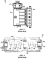
- An example of a typical triplex mud pump 10 shown in FIG. 1A has a power assembly 12, a crosshead assembly 14, and a fluid assembly 16.
- Electric motors (not shown) connect to a pinion shaft 30 that drives the power assembly 12.
- the crosshead assembly 14 converts the rotational movement of the power assembly 12 into reciprocating movement to actuate internal pistons or plungers of the fluid assembly 16.
- the pump's fluid assembly 16 has three internal pistons to pump the mud.
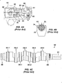
- the pump's power assembly 14 has a crankshaft 20 supported at its ends by double roller bearings 22. Positioned along its intermediate extent, the crankshaft 20 has three eccentric sheaves 24-1...24-3, and three connecting rods 40 mount onto these sheaves 24 with cylindrical roller bearings 26. These connecting rods 40 connect by extension rods (not shown) and the crosshead assembly (14) to the pistons of the pump's fluid assembly 16.
- the crankshaft 20 also has a bull gear 28 positioned between the second and third sheaves 24-2 and 24-3.
- the bull gear 28 interfaces with the pinion shaft (30) and drives the crankshaft 20's rotation.
- the pinion shaft 30 also mounts in the power assembly 14 with roller bearings 32 supporting its ends.
- a pinion gear 38 interfacing with the crankshaft's bull gear 28 drives the crankshaft (20), thereby operating the pistons of the pump's fluid assembly 16.
- the triplex mud pump 10 When used to pump mud, the triplex mud pump 10 produces flow that varies by approximately 23%. For example, the pump 10 produces a maximum flow level of about 106% during certain crankshaft angles and produces a minimum flow level of 83% during other crankshaft angles, resulting in a total flow variation of 23% as the pump's pistons are moved in differing exhaust strokes during the crankshaft's rotation. Because the total flow varies, the pump 10 tends to produce undesirable pressure changes or "noise" in the pumped mud. In turn, this noise interferes with downhole telemetry and other techniques used during measurement-while-drilling (MWD) and logging-while-drilling (LWD) operations.
- MWD measurement-while-drilling
- LWD logging-while-drilling
- well-service pumps In contrast to mud pumps, well-service pumps (WSP) are also used during well operations.
- a well service pump is used to pump fluid at higher pressures than those used to pump mud. Therefore, the well service pumps are typically used to pump high pressure fluid into a well during frac operations or the like.
- An example of a well-service pump 50 is shown in FIG. 2 .
- the well service pump 50 is a quintuplex well service pump, although triplex well service pumps are also used.
- the pump 50 has a power assembly 52, a crosshead assembly 54, and a fluid assembly 56.
- a gear reducer 53 on one side of the pump 50 connects a drive (not shown) to the power assembly 52 to drive the pump 50.
- the pump's power assembly 52 has a crankshaft 60 with five crankpins 62 and an internal main bearing sheave 64.
- the crankpins 62 are offset from the crankshaft 60's axis of rotation and convert the rotation of the crankshaft 60 in to a reciprocating motion for operating pistons (not shown) in the pump's fluid assembly 56.
- Double roller bearings 66 support the crankshaft 60 at both ends of the power assembly 52, and an internal double roller bearing 68 supports the crankshaft 60 at its main bearing sheave 64.
- One end 61 of the crankshaft 60 extends outside the power assembly 52 for coupling to the gear reducer (53; Fig. 2 ) and other drive components.
- connecting rods 70 connect from the crankpins 62 to pistons or plungers 80 via the crosshead assembly 54.
- FIG. 4B shows a typical connection of a connecting rod 70 to a crankpin 62 in the well service pump 50.
- a bearing cap 74 fits on one side of the crankpin 62 and couples to the profiled end of the connecting rod 70.
- the connection uses a sleeve bearing 76 between the rod 70, bearing cap 74, and crankpin 62.
- the connecting rod 70 connects to a crosshead 55 using a wrist pin 72 as shown in FIG. 4A .
- the wrist pin 72 allows the connecting rod 70 to pivot with respect to the crosshead 55, which in turn is connected to the plunger 80.
- an electric motor or an internal combustion engine drives the pump 50 by the gear reducer 53.
- the crankpins 62 reciprocate the connecting rods 70.
- the crossheads 55 reciprocate inside fixed cylinders.
- the plunger 80 coupled to the crosshead 55 also reciprocates between suction and power strokes in the fluid assembly 56. Withdrawal of a plunger 80 during a suction stroke pulls fluid into the assembly 56 through the input valve 82 connected to an inlet hose or pipe (not shown). Subsequently pushed during the power stroke, the plunger 80 then forces the fluid under pressure out through the output valve 84 connected to an outlet hose or pipe (not shown).
- FIG. 4C is an isolated view of such a crankshaft 90 having eccentric sheaves 92-1...92-5 for use in a quintuplex well-service pump.
- External main bearings (not shown) support the crankshaft 90 at its ends 96 in the well-service pumps housing (not shown).
- To drive the crankshaft 90 one end 91 extends beyond the pumps housing for coupling to drive components, such as a gear box.
- the crankshaft 90 has five eccentric sheaves 92-1...92-5 for coupling to connecting rods (not shown) with roller bearings.
- the crankshaft 90 also has two internal main bearing sheaves 94-1, 94-2 for internal main bearings used to support the crankshaft 90 in the pump's housing.
- quintuplex well-service pumps used for pumping frac fluid or the like have been substituted for mud pumps during drilling operations to pump mud.
- the well-service pump has a shorter service life compared to the conventional triplex mud pumps, making use of the well-service pump as a mud pump less desirable in most situations.
- a quintuplex well-service pump produces a great deal of white noise that interferes with MWD and LWD operations, further making the pump's use to pump mud less desirable in most situations.
- the well-service pump is configured for direct drive by a motor and gear box directly coupling on one end of the crankshaft. This direct coupling limits what drives can be used with the pump.
- the direct drive to the crankshaft can produce various issues with noise, balance, wear, and other associated problems that make use of the well-service pump to pump mud less desirable.
- a quintuplex mud pump by extending the conventional arrangement of a triplex mud pump ( e.g ., as shown in FIG. 1B ) to include components for two additional pistons or plungers.
- the actual design for a quintuplex mud pump is not as easy as extending the conventional arrangement, especially in light of the requirements for a mud pump's operation such as service life, noise levels, crankshaft deflection, balance, and other considerations.
- acceptable implementation of a quintuplex mud pump has not been achieved in the art during the long history of mud pump design.
- What is needed is an efficient mud pump that has a long service life and that produces low levels of white noise during operation so as not to interfere with MWD and LWD operations while pumping mud in a well.
- a pump employing a crankshaft to reciprocally drive pistons within cylinders is disclosed in US 3,595,101 (Cooper, Jesse F Jr ), wherein the crankshaft is rotatably supported within the pump housing by a forward and an intermediate thrust bearing unit and a rearward straight bearing unit.
- a self-aligning gear set for maintaining optimal meshing contact between a driving gear and a driven gear is disclosed in US 2007/099746 A1 (Hahlbeck, Ed ), that compensates for shaft deflection under a range of loads.
- the shaft gears When an industrial double helical gear set that has a pair of helical shaft gears meshing with a pair of helical flexible bull gears is operating under a load, the shaft gears have their axial force vectors directed away from the shaft ends.
- the flexible helical bull gears have their axial force vectors directed toward each other such that the shaft and bull gears remain in substantial alignment during load operation of the gear set.
- a triplex plunger pump for liquid cryogen service is disclosed in US 4,494,415 (Elliston, Thomas L ), which includes a power end frame comprising a casing formed of welded plate sections and elongated tubular members interconnected to form a main bearing support structure which minimizes the transmission of pump reaction forces to the casing outer walls.
- crankshaft and its method of manufacture is disclosed in US 4,305,311 (McGill, Kenneth H ), which involves a straight, one piece shaft, with eccentric journals and circular gear base pressed onto the shaft and secured thereto in proper angular orientation.
- a quintuplex mud pump (100), comprising:
- a quintuplex mud pump is a continuous duty, reciprocating plunger/piston pump.
- the mud pump has a crankshaft supported in the pump by external main bearings and uses internal gearing and a pinion shaft to drive the crankshaft.
- Five eccentric sheaves and two internal main bearing sheaves are provided on the crankshaft.
- Each of the main bearing sheaves supports the intermediate extent of crankshaft using bearings.
- One main bearing sheave is disposed between the second and third eccentric sheaves, while the other main bearing sheave is disposed between the third and fourth eccentric sheaves.
- One or more bull gears are also provided on the crankshaft, and the pump's pinion shaft has one or more pinion gears that interface with the one or more bull gears. If one bull gear is used, the interface between the bull and pinion gears can use herringbone or double helical gearing of opposite hand to avoid axial thrust. If two bull gears are used, the interface between the bull and pinion gears can use helical gearing with each having opposite hand to avoid axial thrust. For example, one of two bull gears can disposed between the first and second eccentric sheaves, while the second bull gear can be disposed between fourth and fifth eccentric sheaves. These bull gears can have opposite hand.
- the pump's internal gearing allows the pump to be driven conventionally and packaged in any standard mud pump packaging arrangement. Electric motors (for example, twin motors made by GE) may be used to drive the pump, although the pump's rated input horsepower may be a factor used to determine the type of motor.
- Connecting rods connect to the eccentric sheaves and use roller bearings. During rotation of the crankshaft, these connecting rods transfer the crankshaft's rotational movement to reciprocating motion of the pistons or plungers in the pump's fluid assembly.
- the quintuplex mud pump uses all roller bearings to support its crankshaft and to transfer crankshaft motion to the connecting rods. In this way, the quintuplex mud pump can reduce the white noise typically produced by conventional triplex mud pumps and well service pumps that can interfere with MWD and LWD operations.
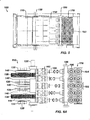
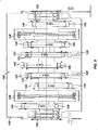
- a quintuplex mud pump 100 shown in FIGS. 5 and 6A-6B has a power assembly 110, a crosshead assembly 150, and a fluid assembly 170.
- Twin drives e.g., electric motors, etc.
- internal gearing within the power assembly 110 converts the rotation of the pinion shaft 130 to rotation of a crankshaft 120.
- the gearing uses pinion gears 138 on the pinion shaft 130 that couple to bull gears 128 on the crankshaft 120 and transfer rotation of the pinion shaft 130 to the crankshaft 120.
- the crankshaft 120 has external main bearings 122 supporting its ends and two internal main bearings 127 supporting its intermediate extent in the assembly 110.
- rotation of the crankshaft 120 reciprocates five independent connecting rods 140.
- Each of the connecting rods 140 couples to a crosshead 160 of the crosshead assembly 150.
- each of the crossheads 160 converts the connecting rod 40's movement into a reciprocating movement of an intermediate pony rod 166.
- the pony rod 166 drives a coupled piston or plunger (not shown) in the fluid assembly 170 that pumps mud from an intake manifold 192 to an output manifold 198.
- the mud pump 100 has five such pistons movable in the fluid assembly 170 for pumping the mud.
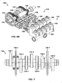
- the crankshaft 120 has five eccentric sheaves 124-1 through 124-5 disposed thereon. Each of these sheaves can mechanically assemble onto the main vertical extent of the crankshaft 120 as opposed to being welded thereon. During rotation of the crankshaft 120, the eccentric sheaves actuate in a firing order of 124-1, 3, 5, 2 and 4 to operate the fluid assembly's pistons (not shown). This order allows the crankshaft 120 to be assembled by permitting the various sheaves to be mounted thereon.
- each of the eccentric sheaves 124-1...124-5 is equidistantly spaced on the crankshaft 120 for balance.
- the crankshaft 120 also has two internal main bearing sheaves 125-1 and 125-2 positioned respectively between the second and third sheaves 124-2 and 124-3 and the third and fourth sheaves 124-3 and 124-4.
- the crankshaft 120 also has two bull gear supports 128-1 and 128-2 disposed thereon, although one bull gear may be used by itself in other embodiments.
- the first bull gear support 128-1 is positioned between the first and second eccentric sheaves 124-1 and 124-2
- the second of the bull gear support 128-2 is positioned between the fourth and fifth eccentric sheaves 124-4 and 124-5.
- each of the sheaves 124-1...124-5, bull gear supports 128-1 & 128-2, and bearing sheaves 125-1 & 125-2 are equidistantly spaced on the crankshaft 120 for balance.
- each of the sheaves 124, 125 and supports 128 are equidistantly spaced from one another by 9-inches between their rotational centers.
- the end sheaves 124-1 and 124-5 can be positioned a little over 9-in. ( e.g. , 9.375-in.) from the ends of the crankshaft 120.
- FIG. 8 shows the crankshaft 120 supported in the power assembly 110 and having the connecting rods 140 mounted thereon.
- double roller bearings 122 support the ends of the crankshaft 120 in the assembly 110.
- main bearings 123 support the intermediate extent of the crankshaft 120 in the assembly 110.
- the main bearings 126 position on the main bearing sheaves 125-1 and 125-2 and are supported by carriers 125 mounted to the assembly 110 at 129.
- the external main bearings 122 are preferably spherical bearings to better support radial and axial loads.
- the internal main bearings 125 preferably use cylindrical bearings.
- Five connector rods 140 use roller bearings 126 to fit on the eccentric sheaves 124-1...124-5. Each of the roller bearings 126 preferably uses cylindrical bearings.
- the rods 140 extend from the sheaves 124-1...124-5 (perpendicular to the figure) and couple the motion of the crankshaft 120 to the fluid assembly (170) via crossheads (160) as is discussed in more detail below with reference to FIGS. 10A-10B .
- the pinion shaft 130 mounts with roller bearings 132 in the power assembly 110 with its free ends 134 extending on both sides of the assembly 110 for coupling to drive components (not shown).
- the pinion gears 138 on the shaft 130 interface with the bull gears 128 on the crankshaft (120).
- the interface uses helical gearing of opposite hand.
- the two pinion gears 138 on the pinion shaft 130 have helical teeth that have an opposite orientation or hand relative to one another. These helical teeth couple in parallel fashion to oppositely oriented helical teeth on the complementary bull gears 128 on the crankshaft 120.
- the opposing orientation of helical teeth on the bull gears 128 and pinion gears 138 can best be seen in FIGS. 6A-6B ).
- the helical gearing transfers rotation of the pinion shaft 130 to the crankshaft 120 in a balanced manner.
- the pinion shaft 130 can have one pinion gear 138, and the crankshaft 120 can have one bull gear 128.
- these single gears 138/128 use herringbone or double helical gearing of opposite hand to avoid imparting axial thrust to the crankshaft 120.
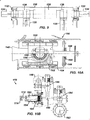
- FIG. 10A shows a crosshead 160 for the quintuplex mud pump.
- the end of the connecting rod 140 couples by a wrist pin 142 and bearing 144 to a crosshead body 162 that is movable in a crosshead guide 164.
- a pony rod 166 coupled to the crosshead body 162 extends through a stuffing box gasket 168 on a diaphragm plate 169. An end of this pony rod 166 in turn couples to additional components of the fluid assembly (170) as discussed below.
- FIG. 10B shows portion of the fluid assembly 170 for the quintuplex mud pump.
- An intermediate rod 172 has a clamp 174 that couples to the pony rod (166; Fig. 10A ) from the crosshead assembly 160 of FIG. 10A .
- the opposite end of the rod 172 couples by another clamp to a piston rod 180 having a piston head 182 on its end.
- the fluid assembly 170 can use a plunger or any other equivalent arrangement so that the terms piston and plunger can be used interchangeably herein.
- the pony rod (166) moves in a liner 184 communicating with a fluid passage 190.
- a triplex mud pump produces a total flow variation of about 23%.
- the pump 100 offers a lower variation in total flow, making the pump 100 better suited for pumping mud and producing less noise that can interfere with MWD and LWD operations.
- the quintuplex mud pump 100 can produce a total flow variation as low as about 7%.
- the quintuplex mud pump 100 can produce a maximum flow level of about 102% during certain crankshaft angles and can produce a minimum flow level of 95% during other crankshaft angles as the pump's five pistons move in their differing strokes during the crankshaft's rotation. Being smoother and closer to ideal, the lower total flow variation of 7% produces less pressure changes or "noise" in the pumped mud that can interfere with MWD and LWD operations.
- a septuplex mud pump may have seven eccentric sheaves, connecting rods, and fluid assembly pistons with at least two bull gears and at least two bearing sheaves on the crankshaft.
- the bull gears can be arranged between first and second eccentric sheaves and sixth and seventh eccentric sheaves on the crankshaft.
- the internal main bearings supporting the crankshaft can be positioned between third and fourth eccentric sheaves and the fourth and fifth eccentric sheaves on the crankshaft.
Landscapes
- Engineering & Computer Science (AREA)
- Mechanical Engineering (AREA)
- General Engineering & Computer Science (AREA)
- Reciprocating Pumps (AREA)
- Rotary Pumps (AREA)
- Details Of Reciprocating Pumps (AREA)
Claims (13)
- Pompe à boue à cinq pistons (100), comprenant :un vilebrequin (120) supporté de manière rotative dans la pompe (100) par plusieurs paliers principaux, le vilebrequin (120) comportant cinq poulies excentriques (124-1 & 124-5) et au moins une couronne principale (128) qui y est agencée, les paliers principaux incluant une première poulie interne du palier principal (125-1) disposée entre les deuxième et troisième poulies excentriques (124-2 & 124-3) et incluant une deuxième poulie interne du palier principal (125-2) disposée entre les troisième et quatrième poulies excentriques (124-3 & 124-4) ;un arbre de pignon (130) pour entraîner le vilebrequin (120), l'arbre de pignon (130) étant supporté de manière rotative dans la pompe (100) et comportant au moins un pignon d'engrenage (138) établissant une interface avec la au moins une couronne principale (128) sur le vilebrequin (120) ; etcinq bielles (140), chacune des bielles (140) étant disposée sur l'une des poulies excentriques (124-1 ... 124-5) du vilebrequin (120) avec un roulement à rouleaux (126).
- Pompe selon la revendication 1, dans laquelle les plusieurs paliers principaux comprennent deux paliers principaux externes (122) et deux paliers principaux internes (127), le vilebrequin (120) comprenant des première et deuxième poulies internes du palier principal (125-1 & 125-2) pour les paliers principaux internes (127).
- Pompe selon les revendications 1 ou 2, comprenant en outre cinq pistons (182) pour pomper la boue, chacune des bielles (140) étant accouplée à l'un des pistons (182).
- Pompe selon la revendication 3, dans laquelle chacune des bielles (140) est accouplée à une traverse (160) par un axe de liaison, et dans laquelle la traverse (160) est accouplée au piston (182).
- Pompe selon l'une quelconque des revendications 1 à 4, dans laquelle l'arbre de pignon (130) comporte des extrémités opposées s'étendant à partir de la pompe (100) en vue d'un accouplement à des composants d'entraînement.
- Pompe selon l'une quelconque des revendications 1 à 5, dans laquelle le au moins un pignon d'engrenage (138) et la au moins une couronne principale (128) comprennent des engrenages à chevrons.
- Pompe selon l'une quelconque des revendications 1 à 6, dans laquelle la au moins une couronne principale (128) comprend des première et deuxième couronnes principales (128-1 & 128-2) qui y sont disposées, et dans laquelle le au moins un pignon d'engrenage (138) comprend des premier et deuxième pignons d'engrenage (138-1 & 138-2) qui y sont disposés et établissant une interface avec les première et deuxième couronnes principales (128-1 & 128-2).
- Pompe selon la revendication 7, dans laquelle la première couronne principale (128-1) est disposée entre les première et deuxième poulies excentriques (124-1 & 124-2), et dans laquelle la deuxième couronne principale (128-2) est disposée entre les quatrième et cinquième poulies excentriques (124-4 & 124-5).
- Pompe selon les revendications 7 ou 8, dans laquelle les cinq poulies excentriques (124-1 ... 124-5), les première et deuxième poulies internes du palier principal (125-1 & 125-2) et les première et deuxième couronnes principales (128-1 & 128-2) sont espacées d'une distance égale les unes des autres sur le vilebrequin (120).
- Pompe selon l'une quelconque des revendications 7 à 9, dans laquelle les premier et deuxième pignons d'engrenage (138-1 & 138-2) comprennent des engrenages hélicoïdaux à orientation opposée, et dans laquelle les première et deuxième couronnes principales (128-1 & 128-2) comprennent des engrenages hélicoïdaux à orientation opposée complémentaires aux pignons d'engrenage (138-1 & 138-2).
- Pompe selon la revendication 2, dans laquelle chacun des deux paliers principaux externes (122) est un palier sphérique.
- Pompe selon la revendication 2, dans laquelle chacun des deux paliers principaux internes (127) comporte un palier cylindrique.
- Pompe selon les revendications 1 ou 2, dans laquelle chacun des paliers à rouleaux (126) pour les bielles (140) comporte un palier cylindrique.
Applications Claiming Priority (2)
| Application Number | Priority Date | Filing Date | Title |
|---|---|---|---|
| US97795607P | 2007-10-05 | 2007-10-05 | |
| PCT/US2008/078720 WO2009046280A1 (fr) | 2007-10-05 | 2008-10-03 | Pompe à boue à cinq pistons |
Publications (3)
| Publication Number | Publication Date |
|---|---|
| EP2205877A1 EP2205877A1 (fr) | 2010-07-14 |
| EP2205877A4 EP2205877A4 (fr) | 2013-09-18 |
| EP2205877B1 true EP2205877B1 (fr) | 2017-09-27 |
Family
ID=40523397
Family Applications (1)
| Application Number | Title | Priority Date | Filing Date |
|---|---|---|---|
| EP08835635.7A Not-in-force EP2205877B1 (fr) | 2007-10-05 | 2008-10-03 | Pompe à boue à cinq pistons |
Country Status (5)
| Country | Link |
|---|---|
| US (1) | US8083504B2 (fr) |
| EP (1) | EP2205877B1 (fr) |
| CA (1) | CA2696683C (fr) |
| NO (1) | NO2205877T3 (fr) |
| WO (1) | WO2009046280A1 (fr) |
Families Citing this family (141)
| Publication number | Priority date | Publication date | Assignee | Title |
|---|---|---|---|---|
| US9188123B2 (en) | 2009-08-13 | 2015-11-17 | Schlumberger Technology Corporation | Pump assembly |
| US8601687B2 (en) * | 2009-08-13 | 2013-12-10 | Schlumberger Technology Corporation | Pump body |
| MX344357B (es) | 2009-09-03 | 2016-12-14 | Schlumberger Tech B V * | Montaje de bomba. |
| CA2772741A1 (fr) | 2009-09-03 | 2011-03-10 | Schlumberger Canada Limited | Corps de pompe |
| US9341179B2 (en) | 2010-02-26 | 2016-05-17 | Schlumberger Technology Corporation | Precompression effect in pump body |
| US8579599B2 (en) * | 2010-03-26 | 2013-11-12 | Schlumberger Technology Corporation | System, apparatus, and method for rapid pump displacement configuration |
| CN101985925A (zh) * | 2010-12-06 | 2011-03-16 | 中国石油集团西部钻探工程有限公司 | 耐用钻井泵 |
| CA2828614C (fr) * | 2011-03-04 | 2016-01-05 | Gea Farm Technologies Canada Inc./Division Gea Houle | Ensemble pompes modulaires |
| US11255173B2 (en) | 2011-04-07 | 2022-02-22 | Typhon Technology Solutions, Llc | Mobile, modular, electrically powered system for use in fracturing underground formations using liquid petroleum gas |
| US9140110B2 (en) | 2012-10-05 | 2015-09-22 | Evolution Well Services, Llc | Mobile, modular, electrically powered system for use in fracturing underground formations using liquid petroleum gas |
| US11708752B2 (en) | 2011-04-07 | 2023-07-25 | Typhon Technology Solutions (U.S.), Llc | Multiple generator mobile electric powered fracturing system |
| US8696324B2 (en) * | 2011-06-13 | 2014-04-15 | Jason C. Williams | Quintuplex mud pump |
| EP2543812B1 (fr) * | 2011-07-08 | 2014-11-05 | Welltec A/S | Pompe hydraulique de fond de trou |
| CN102493940A (zh) * | 2011-12-16 | 2012-06-13 | 湖南湖大三佳车辆技术装备有限公司 | 活塞式排污机 |
| US10119381B2 (en) | 2012-11-16 | 2018-11-06 | U.S. Well Services, LLC | System for reducing vibrations in a pressure pumping fleet |
| US10407990B2 (en) | 2012-11-16 | 2019-09-10 | U.S. Well Services, LLC | Slide out pump stand for hydraulic fracturing equipment |
| US9970278B2 (en) | 2012-11-16 | 2018-05-15 | U.S. Well Services, LLC | System for centralized monitoring and control of electric powered hydraulic fracturing fleet |
| US11449018B2 (en) | 2012-11-16 | 2022-09-20 | U.S. Well Services, LLC | System and method for parallel power and blackout protection for electric powered hydraulic fracturing |
| US10020711B2 (en) | 2012-11-16 | 2018-07-10 | U.S. Well Services, LLC | System for fueling electric powered hydraulic fracturing equipment with multiple fuel sources |
| US10232332B2 (en) | 2012-11-16 | 2019-03-19 | U.S. Well Services, Inc. | Independent control of auger and hopper assembly in electric blender system |
| US11476781B2 (en) | 2012-11-16 | 2022-10-18 | U.S. Well Services, LLC | Wireline power supply during electric powered fracturing operations |
| US9893500B2 (en) | 2012-11-16 | 2018-02-13 | U.S. Well Services, LLC | Switchgear load sharing for oil field equipment |
| US9840901B2 (en) | 2012-11-16 | 2017-12-12 | U.S. Well Services, LLC | Remote monitoring for hydraulic fracturing equipment |
| US11959371B2 (en) | 2012-11-16 | 2024-04-16 | Us Well Services, Llc | Suction and discharge lines for a dual hydraulic fracturing unit |
| US10254732B2 (en) | 2012-11-16 | 2019-04-09 | U.S. Well Services, Inc. | Monitoring and control of proppant storage from a datavan |
| US9995218B2 (en) | 2012-11-16 | 2018-06-12 | U.S. Well Services, LLC | Turbine chilling for oil field power generation |
| US10526882B2 (en) | 2012-11-16 | 2020-01-07 | U.S. Well Services, LLC | Modular remote power generation and transmission for hydraulic fracturing system |
| US9611728B2 (en) | 2012-11-16 | 2017-04-04 | U.S. Well Services Llc | Cold weather package for oil field hydraulics |
| US9650871B2 (en) | 2012-11-16 | 2017-05-16 | Us Well Services Llc | Safety indicator lights for hydraulic fracturing pumps |
| US9745840B2 (en) | 2012-11-16 | 2017-08-29 | Us Well Services Llc | Electric powered pump down |
| US10036238B2 (en) | 2012-11-16 | 2018-07-31 | U.S. Well Services, LLC | Cable management of electric powered hydraulic fracturing pump unit |
| US9650879B2 (en) * | 2012-11-16 | 2017-05-16 | Us Well Services Llc | Torsional coupling for electric hydraulic fracturing fluid pumps |
| US9410410B2 (en) | 2012-11-16 | 2016-08-09 | Us Well Services Llc | System for pumping hydraulic fracturing fluid using electric pumps |
| US20140147291A1 (en) * | 2012-11-28 | 2014-05-29 | Baker Hughes Incorporated | Reciprocating pump assembly and method thereof |
| CN103032053B (zh) * | 2012-12-19 | 2015-09-16 | 西安石油大学 | 一种短冲程偏心齿轮式抽油机 |
| US20140219824A1 (en) * | 2013-02-06 | 2014-08-07 | Baker Hughes Incorporated | Pump system and method thereof |
| US8707853B1 (en) | 2013-03-15 | 2014-04-29 | S.P.M. Flow Control, Inc. | Reciprocating pump assembly |
| CN103321867B (zh) * | 2013-07-17 | 2015-09-23 | 焦作锦标机械制造有限公司 | 轻型大功率钻井泥浆泵 |
| CN103541880B (zh) * | 2013-10-23 | 2016-02-10 | 四川宏华石油设备有限公司 | 钻井用五缸泵及其五缸泵的斜齿轮安装方法 |
| US20150275891A1 (en) * | 2014-03-31 | 2015-10-01 | Schlumberger Technology Corporation | Integrated motor and pump assembly |
| AU2015279647A1 (en) | 2014-06-27 | 2017-01-19 | S.P.M. Flow Control, Inc. | Pump drivetrain damper system and control systems and methods for same |
| AR096926A1 (es) * | 2014-07-15 | 2016-02-03 | Yorio Pablo Martín | Dispositivo de reducción de cargas para sistemas de bombeo de pozos subterráneos y sistema de bombeo que utiliza el mismo |
| US10087992B2 (en) | 2014-07-25 | 2018-10-02 | S.P.M. Flow Control, Inc. | Bearing system for reciprocating pump and method of assembly |
| EP3719281B1 (fr) | 2014-12-19 | 2022-11-23 | Typhon Technology Solutions, LLC | Production d'énergie électrique mobile pour fracturation hydraulique de formations géologiques sous la surface |
| US10378326B2 (en) * | 2014-12-19 | 2019-08-13 | Typhon Technology Solutions, Llc | Mobile fracturing pump transport for hydraulic fracturing of subsurface geological formations |
| US10352321B2 (en) | 2014-12-22 | 2019-07-16 | S.P.M. Flow Control, Inc. | Reciprocating pump with dual circuit power end lubrication system |
| US11047371B2 (en) | 2015-01-22 | 2021-06-29 | Spx Flow Technology Norderstedt Gmbh | Process pump having a crank drive |
| USD759728S1 (en) | 2015-07-24 | 2016-06-21 | S.P.M. Flow Control, Inc. | Power end frame segment |
| CN105134536A (zh) * | 2015-09-30 | 2015-12-09 | 焦作锦标机械制造有限公司 | 一种轻型大功率四缸泥浆泵 |
| US10436766B1 (en) | 2015-10-12 | 2019-10-08 | S.P.M. Flow Control, Inc. | Monitoring lubricant in hydraulic fracturing pump system |
| US10184470B2 (en) * | 2016-01-15 | 2019-01-22 | W. H. Barnett, JR. | Segmented fluid end |
| US10677119B2 (en) * | 2016-03-01 | 2020-06-09 | Cummins Inc. | Systems and methods for reducing the oil volume and windage in fuel pumps |
| EP3267035B1 (fr) * | 2016-07-07 | 2020-12-09 | Cameron Technologies Limited | Ensemble d'étanchéité de pompe de boue |
| EP3267034B1 (fr) * | 2016-07-07 | 2020-05-13 | Cameron Technologies Limited | Ensemble de pompe à boue à auto-alignement |
| EP3267036B1 (fr) * | 2016-07-07 | 2020-09-02 | Cameron Technologies Limited | Ensemble de pompe de boue a charge equilibree |
| CN106089617B (zh) * | 2016-08-02 | 2018-09-28 | 山东科瑞泵业有限公司 | 一种新型钻井泥浆泵 |
| CN106050895B (zh) * | 2016-08-04 | 2019-01-18 | 兰州兰石集团有限公司 | 双齿圈六缸泥浆泵 |
| CN106089679B (zh) * | 2016-08-04 | 2018-04-03 | 兰州兰石石油装备工程股份有限公司 | 泥浆泵三级偏心双齿圈曲轴 |
| CA2987665C (fr) | 2016-12-02 | 2021-10-19 | U.S. Well Services, LLC | Systeme de distribution d'alimentation en tension constante destine a un systeme de fracturation hydraulique electrique |
| US11624326B2 (en) | 2017-05-21 | 2023-04-11 | Bj Energy Solutions, Llc | Methods and systems for supplying fuel to gas turbine engines |
| US10280724B2 (en) | 2017-07-07 | 2019-05-07 | U.S. Well Services, Inc. | Hydraulic fracturing equipment with non-hydraulic power |
| AR113285A1 (es) | 2017-10-05 | 2020-03-11 | U S Well Services Llc | Método y sistema de flujo de lodo de fractura instrumentada |
| WO2019075475A1 (fr) | 2017-10-13 | 2019-04-18 | U.S. Well Services, LLC | Système et procédé de fracturation automatique |
| WO2019084283A1 (fr) | 2017-10-25 | 2019-05-02 | U.S. Well Services, LLC | Système et procédé de fracturation intelligente |
| WO2019113153A1 (fr) | 2017-12-05 | 2019-06-13 | U.S. Well Services, Inc. | Configuration de pompage de puissance élevée pour un système de fracturation hydraulique électrique |
| CA3084596A1 (fr) | 2017-12-05 | 2019-06-13 | U.S. Well Services, LLC | Pompes a pistons multiples et systemes d'entrainement associes |
| US11680631B2 (en) | 2017-12-06 | 2023-06-20 | Spm Oil & Gas Inc. | Pump gear |
| WO2019152981A1 (fr) | 2018-02-05 | 2019-08-08 | U.S. Well Services, Inc. | Gestion de charge électrique de micro-réseau |
| CA3097051A1 (fr) | 2018-04-16 | 2019-10-24 | U.S. Well Services, LLC | Parc de fracturation hydraulique hybride |
| WO2019241783A1 (fr) | 2018-06-15 | 2019-12-19 | U.S. Well Services, Inc. | Unité d'alimentation mobile intégrée pour fracturation hydraulique |
| WO2020033181A1 (fr) * | 2018-08-06 | 2020-02-13 | Typhon Technology Solutions, Llc | Mise en prise et désolidarisation avec pompes de style à boîte d'engrenage externe |
| WO2020056258A1 (fr) | 2018-09-14 | 2020-03-19 | U.S. Well Services, LLC | Support de colonne montante pour sites de puits |
| US11208878B2 (en) | 2018-10-09 | 2021-12-28 | U.S. Well Services, LLC | Modular switchgear system and power distribution for electric oilfield equipment |
| US10914155B2 (en) | 2018-10-09 | 2021-02-09 | U.S. Well Services, LLC | Electric powered hydraulic fracturing pump system with single electric powered multi-plunger pump fracturing trailers, filtration units, and slide out platform |
| US20220090588A1 (en) * | 2018-12-03 | 2022-03-24 | Centerline Manufacturing Llc | Duplex drive head |
| US11578577B2 (en) | 2019-03-20 | 2023-02-14 | U.S. Well Services, LLC | Oversized switchgear trailer for electric hydraulic fracturing |
| CN109869294A (zh) * | 2019-04-19 | 2019-06-11 | 烟台杰瑞石油装备技术有限公司 | 一种超大功率五缸柱塞泵 |
| US11578710B2 (en) | 2019-05-02 | 2023-02-14 | Kerr Machine Co. | Fracturing pump with in-line fluid end |
| CA3139970A1 (fr) | 2019-05-13 | 2020-11-19 | U.S. Well Services, LLC | Commande vectorielle sans codeur pour variateur de frequence dans des applications de fracturation hydraulique |
| US11560845B2 (en) | 2019-05-15 | 2023-01-24 | Bj Energy Solutions, Llc | Mobile gas turbine inlet air conditioning system and associated methods |
| US11753916B2 (en) | 2019-05-31 | 2023-09-12 | Stewart & Stevenson Llc | Integrated fracking system |
| CA3143050A1 (fr) | 2019-06-10 | 2020-12-17 | U.S. Well Services, LLC | Dispositif de rechauffeur de combustible gazeux integre pour equipement mobile de conditionnement de combustible |
| CA3148496A1 (fr) | 2019-07-26 | 2021-02-04 | Typhon Technology Solutions, Llc | Surveillance et commande de systeme de fracturation hydraulique faisant appel a l'intelligence artificielle |
| US11542786B2 (en) | 2019-08-01 | 2023-01-03 | U.S. Well Services, LLC | High capacity power storage system for electric hydraulic fracturing |
| US10815764B1 (en) | 2019-09-13 | 2020-10-27 | Bj Energy Solutions, Llc | Methods and systems for operating a fleet of pumps |
| US11015594B2 (en) | 2019-09-13 | 2021-05-25 | Bj Energy Solutions, Llc | Systems and method for use of single mass flywheel alongside torsional vibration damper assembly for single acting reciprocating pump |
| US10961914B1 (en) | 2019-09-13 | 2021-03-30 | BJ Energy Solutions, LLC Houston | Turbine engine exhaust duct system and methods for noise dampening and attenuation |
| US11015536B2 (en) | 2019-09-13 | 2021-05-25 | Bj Energy Solutions, Llc | Methods and systems for supplying fuel to gas turbine engines |
| US11604113B2 (en) | 2019-09-13 | 2023-03-14 | Bj Energy Solutions, Llc | Fuel, communications, and power connection systems and related methods |
| CA3092865C (fr) | 2019-09-13 | 2023-07-04 | Bj Energy Solutions, Llc | Sources d`alimentation et reseaux de transmission pour du materiel auxiliaire a bord d`unites de fracturation hydraulique et methodes connexes |
| CA3092829C (fr) | 2019-09-13 | 2023-08-15 | Bj Energy Solutions, Llc | Methodes et systemes d`alimentation de turbines a gaz en carburant |
| US11002189B2 (en) | 2019-09-13 | 2021-05-11 | Bj Energy Solutions, Llc | Mobile gas turbine inlet air conditioning system and associated methods |
| US10895202B1 (en) | 2019-09-13 | 2021-01-19 | Bj Energy Solutions, Llc | Direct drive unit removal system and associated methods |
| CA3092859A1 (fr) | 2019-09-13 | 2021-03-13 | Bj Energy Solutions, Llc | Carburant, communications, systemes d`alimentation et methodes connexes |
| US10989180B2 (en) | 2019-09-13 | 2021-04-27 | Bj Energy Solutions, Llc | Power sources and transmission networks for auxiliary equipment onboard hydraulic fracturing units and associated methods |
| US11313359B2 (en) * | 2019-10-01 | 2022-04-26 | St9 Gas And Oil, Llc | Electric drive pump for well stimulation |
| US11459863B2 (en) | 2019-10-03 | 2022-10-04 | U.S. Well Services, LLC | Electric powered hydraulic fracturing pump system with single electric powered multi-plunger fracturing pump |
| US11719230B2 (en) * | 2019-11-14 | 2023-08-08 | Stewart & Stevenson Llc | Well servicing pump with electric motor |
| US20220397107A1 (en) | 2019-11-18 | 2022-12-15 | Kerr Machine Co. | Fluid end assembly |
| US11578711B2 (en) | 2019-11-18 | 2023-02-14 | Kerr Machine Co. | Fluid routing plug |
| US11644018B2 (en) | 2019-11-18 | 2023-05-09 | Kerr Machine Co. | Fluid end |
| US11635068B2 (en) | 2019-11-18 | 2023-04-25 | Kerr Machine Co. | Modular power end |
| US11686296B2 (en) | 2019-11-18 | 2023-06-27 | Kerr Machine Co. | Fluid routing plug |
| US11346339B2 (en) | 2019-11-18 | 2022-05-31 | Kerr Machine Co. | High pressure pump |
| CN110905907A (zh) * | 2019-12-06 | 2020-03-24 | 成都鑫泽机械有限公司 | 一种适用于五缸钻井泥浆泵的焊接曲轴及其焊接方法 |
| US11009162B1 (en) | 2019-12-27 | 2021-05-18 | U.S. Well Services, LLC | System and method for integrated flow supply line |
| US11885206B2 (en) | 2019-12-30 | 2024-01-30 | U.S. Well Services, LLC | Electric motor driven transportation mechanisms for fracturing blenders |
| US11846167B2 (en) | 2019-12-30 | 2023-12-19 | U.S. Well Services, LLC | Blender tub overflow catch |
| US11560887B2 (en) | 2019-12-31 | 2023-01-24 | U.S. Well Services, LLC | Segmented fluid end plunger pump |
| US11492886B2 (en) | 2019-12-31 | 2022-11-08 | U.S. Wells Services, LLC | Self-regulating FRAC pump suction stabilizer/dampener |
| US11960305B2 (en) | 2019-12-31 | 2024-04-16 | U.S. Well Services, LLC | Automated blender bucket testing and calibration |
| US20210207589A1 (en) * | 2020-01-07 | 2021-07-08 | Moien Ibrahim Louzon | Fracturing pump assembly |
| US11708829B2 (en) | 2020-05-12 | 2023-07-25 | Bj Energy Solutions, Llc | Cover for fluid systems and related methods |
| US10968837B1 (en) | 2020-05-14 | 2021-04-06 | Bj Energy Solutions, Llc | Systems and methods utilizing turbine compressor discharge for hydrostatic manifold purge |
| US11428165B2 (en) | 2020-05-15 | 2022-08-30 | Bj Energy Solutions, Llc | Onboard heater of auxiliary systems using exhaust gases and associated methods |
| US11208880B2 (en) | 2020-05-28 | 2021-12-28 | Bj Energy Solutions, Llc | Bi-fuel reciprocating engine to power direct drive turbine fracturing pumps onboard auxiliary systems and related methods |
| US11208953B1 (en) | 2020-06-05 | 2021-12-28 | Bj Energy Solutions, Llc | Systems and methods to enhance intake air flow to a gas turbine engine of a hydraulic fracturing unit |
| US10961908B1 (en) | 2020-06-05 | 2021-03-30 | Bj Energy Solutions, Llc | Systems and methods to enhance intake air flow to a gas turbine engine of a hydraulic fracturing unit |
| US11109508B1 (en) | 2020-06-05 | 2021-08-31 | Bj Energy Solutions, Llc | Enclosure assembly for enhanced cooling of direct drive unit and related methods |
| US11022526B1 (en) | 2020-06-09 | 2021-06-01 | Bj Energy Solutions, Llc | Systems and methods for monitoring a condition of a fracturing component section of a hydraulic fracturing unit |
| US11066915B1 (en) | 2020-06-09 | 2021-07-20 | Bj Energy Solutions, Llc | Methods for detection and mitigation of well screen out |
| US10954770B1 (en) | 2020-06-09 | 2021-03-23 | Bj Energy Solutions, Llc | Systems and methods for exchanging fracturing components of a hydraulic fracturing unit |
| US11111768B1 (en) | 2020-06-09 | 2021-09-07 | Bj Energy Solutions, Llc | Drive equipment and methods for mobile fracturing transportation platforms |
| US11933153B2 (en) | 2020-06-22 | 2024-03-19 | Bj Energy Solutions, Llc | Systems and methods to operate hydraulic fracturing units using automatic flow rate and/or pressure control |
| US11939853B2 (en) | 2020-06-22 | 2024-03-26 | Bj Energy Solutions, Llc | Systems and methods providing a configurable staged rate increase function to operate hydraulic fracturing units |
| US11028677B1 (en) | 2020-06-22 | 2021-06-08 | Bj Energy Solutions, Llc | Stage profiles for operations of hydraulic systems and associated methods |
| US11125066B1 (en) | 2020-06-22 | 2021-09-21 | Bj Energy Solutions, Llc | Systems and methods to operate a dual-shaft gas turbine engine for hydraulic fracturing |
| US11473413B2 (en) | 2020-06-23 | 2022-10-18 | Bj Energy Solutions, Llc | Systems and methods to autonomously operate hydraulic fracturing units |
| US11466680B2 (en) | 2020-06-23 | 2022-10-11 | Bj Energy Solutions, Llc | Systems and methods of utilization of a hydraulic fracturing unit profile to operate hydraulic fracturing units |
| US11220895B1 (en) | 2020-06-24 | 2022-01-11 | Bj Energy Solutions, Llc | Automated diagnostics of electronic instrumentation in a system for fracturing a well and associated methods |
| US11149533B1 (en) | 2020-06-24 | 2021-10-19 | Bj Energy Solutions, Llc | Systems to monitor, detect, and/or intervene relative to cavitation and pulsation events during a hydraulic fracturing operation |
| US11193361B1 (en) | 2020-07-17 | 2021-12-07 | Bj Energy Solutions, Llc | Methods, systems, and devices to enhance fracturing fluid delivery to subsurface formations during high-pressure fracturing operations |
| US20230304483A1 (en) * | 2020-08-10 | 2023-09-28 | Spm Oil & Gas Inc. | Keyless gear timing assembly for a reciprocating pump |
| US11920583B2 (en) | 2021-03-05 | 2024-03-05 | Kerr Machine Co. | Fluid end with clamped retention |
| US11639654B2 (en) | 2021-05-24 | 2023-05-02 | Bj Energy Solutions, Llc | Hydraulic fracturing pumps to enhance flow of fracturing fluid into wellheads and related methods |
| US11946465B2 (en) | 2021-08-14 | 2024-04-02 | Kerr Machine Co. | Packing seal assembly |
| US11808364B2 (en) | 2021-11-11 | 2023-11-07 | Kerr Machine Co. | Valve body |
| US11965504B2 (en) | 2022-02-11 | 2024-04-23 | Kerr Machine Co. | Manifold assembly |
| US11953000B2 (en) | 2022-04-25 | 2024-04-09 | Kerr Machine Co. | Linear drive assembly |
| US11725582B1 (en) | 2022-04-28 | 2023-08-15 | Typhon Technology Solutions (U.S.), Llc | Mobile electric power generation system |
| US11955782B1 (en) | 2022-11-01 | 2024-04-09 | Typhon Technology Solutions (U.S.), Llc | System and method for fracturing of underground formations using electric grid power |
Family Cites Families (9)
| Publication number | Priority date | Publication date | Assignee | Title |
|---|---|---|---|---|
| US3595101A (en) | 1969-07-11 | 1971-07-27 | Gaso Pump And Burner Mfg Co | Reciprocating pump having improved crankshaft bearing arrangement |
| US4032265A (en) * | 1974-07-19 | 1977-06-28 | United States Steel Corporation | Suction stabilizer for reciprocating pumps and stabilizing method |
| US4305311A (en) * | 1975-04-21 | 1981-12-15 | Dresser Industries, Inc. | Crankshaft construction |
| US4494415A (en) * | 1982-03-25 | 1985-01-22 | Hydra-Rig, Incorporated | Liquid nitrogen pump |
| US5246355A (en) * | 1992-07-10 | 1993-09-21 | Special Projects Manufacturing, Inc. | Well service pumping assembly |
| US5839888A (en) * | 1997-03-18 | 1998-11-24 | Geological Equipment Corp. | Well service pump systems having offset wrist pins |
| US20040213677A1 (en) * | 2003-04-24 | 2004-10-28 | Matzner Mark D. | Monitoring system for reciprocating pumps |
| US7404704B2 (en) * | 2003-04-30 | 2008-07-29 | S.P.M. Flow Control, Inc. | Manifold assembly for reciprocating pump |
| US20070099746A1 (en) | 2005-10-31 | 2007-05-03 | Gardner Denver, Inc. | Self aligning gear set |
-
2008
- 2008-10-03 CA CA2696683A patent/CA2696683C/fr not_active Expired - Fee Related
- 2008-10-03 NO NO08835635A patent/NO2205877T3/no unknown
- 2008-10-03 EP EP08835635.7A patent/EP2205877B1/fr not_active Not-in-force
- 2008-10-03 US US12/244,946 patent/US8083504B2/en not_active Expired - Fee Related
- 2008-10-03 WO PCT/US2008/078720 patent/WO2009046280A1/fr active Application Filing
Non-Patent Citations (1)
| Title |
|---|
| None * |
Also Published As
| Publication number | Publication date |
|---|---|
| EP2205877A4 (fr) | 2013-09-18 |
| NO2205877T3 (fr) | 2018-02-24 |
| CA2696683A1 (fr) | 2009-04-09 |
| CA2696683C (fr) | 2012-11-27 |
| EP2205877A1 (fr) | 2010-07-14 |
| US8083504B2 (en) | 2011-12-27 |
| US20090092510A1 (en) | 2009-04-09 |
| WO2009046280A1 (fr) | 2009-04-09 |
Similar Documents
| Publication | Publication Date | Title |
|---|---|---|
| EP2205877B1 (fr) | Pompe à boue à cinq pistons | |
| CN210769169U (zh) | 一种大功率五缸柱塞泵 | |
| US7610847B2 (en) | Pump crosshead and connecting rod assembly | |
| US20040219040A1 (en) | Direct drive reciprocating pump | |
| CN105264275B (zh) | 往复式泵组件 | |
| US5839888A (en) | Well service pump systems having offset wrist pins | |
| US8696324B2 (en) | Quintuplex mud pump | |
| US20160369792A1 (en) | Connecting rod and crosshead assembly for enhancing the performance of a reciprocating pump | |
| US20100242720A1 (en) | Bimetallic Crosshead | |
| CN1908435A (zh) | 往复式泵装置 | |
| CN107725712A (zh) | 一种往复‑旋转运动转换机构及其水泵 | |
| US6749408B1 (en) | Piston pump | |
| CN216518438U (zh) | 柱塞泵 | |
| RU92698U1 (ru) | Насос буровой трехпоршневой одностороннего действия типа 8т-650 | |
| EP0348485A1 (fr) | Pompe ou moteur comportant au moins un corps de piston dispose dans un logement cylindrique. | |
| CN108006186B (zh) | 一种往复-旋转运动转换机构及水泵 | |
| CN1271334C (zh) | 五柱塞四支承结构的乳化液泵 | |
| US6793471B2 (en) | Fluid machine | |
| RU2022118C1 (ru) | Поршневая машина | |
| US20220090588A1 (en) | Duplex drive head | |
| WO2022020980A1 (fr) | Pompe à plongeurs à sept cylindres | |
| CN105134581A (zh) | 一种压裂泵及压裂车 | |
| JP3770260B2 (ja) | ピストン機関 | |
| EP2279349B1 (fr) | Système de commande pour générateur d'ondes de pression | |
| RU2307952C1 (ru) | Привод многоцилиндрового насоса |
Legal Events
| Date | Code | Title | Description |
|---|---|---|---|
| PUAI | Public reference made under article 153(3) epc to a published international application that has entered the european phase |
Free format text: ORIGINAL CODE: 0009012 |
|
| 17P | Request for examination filed |
Effective date: 20100406 |
|
| AK | Designated contracting states |
Kind code of ref document: A1 Designated state(s): AT BE BG CH CY CZ DE DK EE ES FI FR GB GR HR HU IE IS IT LI LT LU LV MC MT NL NO PL PT RO SE SI SK TR |
|
| AX | Request for extension of the european patent |
Extension state: AL BA MK RS |
|
| RIN1 | Information on inventor provided before grant (corrected) |
Inventor name: WILLIAMS, MICHAEL, R. Inventor name: WILLIAMS, JASON, C. Inventor name: WILLIAMS, ELLIS |
|
| DAX | Request for extension of the european patent (deleted) | ||
| REG | Reference to a national code |
Ref country code: DE Ref legal event code: R079 Ref document number: 602008052286 Country of ref document: DE Free format text: PREVIOUS MAIN CLASS: F16C0003040000 Ipc: F04B0001000000 |
|
| A4 | Supplementary search report drawn up and despatched |
Effective date: 20130819 |
|
| RIC1 | Information provided on ipc code assigned before grant |
Ipc: F04B 1/00 20060101AFI20130812BHEP Ipc: F04B 23/06 20060101ALI20130812BHEP Ipc: F04B 15/02 20060101ALI20130812BHEP |
|
| RAP1 | Party data changed (applicant data changed or rights of an application transferred) |
Owner name: WEATHERFORD/LAMB, INC. |
|
| RAP1 | Party data changed (applicant data changed or rights of an application transferred) |
Owner name: WEATHERFORD TECHNOLOGY HOLDINGS, LLC |
|
| GRAP | Despatch of communication of intention to grant a patent |
Free format text: ORIGINAL CODE: EPIDOSNIGR1 |
|
| INTG | Intention to grant announced |
Effective date: 20170127 |
|
| RIN1 | Information on inventor provided before grant (corrected) |
Inventor name: WILLIAMS, ELLIS Inventor name: WILLIAMS, JASON C. Inventor name: WILLIAMS, MICHAEL R. |
|
| GRAJ | Information related to disapproval of communication of intention to grant by the applicant or resumption of examination proceedings by the epo deleted |
Free format text: ORIGINAL CODE: EPIDOSDIGR1 |
|
| INTC | Intention to grant announced (deleted) | ||
| GRAR | Information related to intention to grant a patent recorded |
Free format text: ORIGINAL CODE: EPIDOSNIGR71 |
|
| GRAS | Grant fee paid |
Free format text: ORIGINAL CODE: EPIDOSNIGR3 |
|
| INTG | Intention to grant announced |
Effective date: 20170720 |
|
| GRAA | (expected) grant |
Free format text: ORIGINAL CODE: 0009210 |
|
| AK | Designated contracting states |
Kind code of ref document: B1 Designated state(s): AT BE BG CH CY CZ DE DK EE ES FI FR GB GR HR HU IE IS IT LI LT LU LV MC MT NL NO PL PT RO SE SI SK TR |
|
| REG | Reference to a national code |
Ref country code: GB Ref legal event code: FG4D |
|
| REG | Reference to a national code |
Ref country code: CH Ref legal event code: EP |
|
| REG | Reference to a national code |
Ref country code: AT Ref legal event code: REF Ref document number: 932225 Country of ref document: AT Kind code of ref document: T Effective date: 20171015 |
|
| REG | Reference to a national code |
Ref country code: IE Ref legal event code: FG4D |
|
| REG | Reference to a national code |
Ref country code: DE Ref legal event code: R096 Ref document number: 602008052286 Country of ref document: DE |
|
| REG | Reference to a national code |
Ref country code: NL Ref legal event code: FP |
|
| REG | Reference to a national code |
Ref country code: NO Ref legal event code: T2 Effective date: 20170927 |
|
| PG25 | Lapsed in a contracting state [announced via postgrant information from national office to epo] |
Ref country code: SE Free format text: LAPSE BECAUSE OF FAILURE TO SUBMIT A TRANSLATION OF THE DESCRIPTION OR TO PAY THE FEE WITHIN THE PRESCRIBED TIME-LIMIT Effective date: 20170927 Ref country code: HR Free format text: LAPSE BECAUSE OF FAILURE TO SUBMIT A TRANSLATION OF THE DESCRIPTION OR TO PAY THE FEE WITHIN THE PRESCRIBED TIME-LIMIT Effective date: 20170927 Ref country code: FI Free format text: LAPSE BECAUSE OF FAILURE TO SUBMIT A TRANSLATION OF THE DESCRIPTION OR TO PAY THE FEE WITHIN THE PRESCRIBED TIME-LIMIT Effective date: 20170927 Ref country code: LT Free format text: LAPSE BECAUSE OF FAILURE TO SUBMIT A TRANSLATION OF THE DESCRIPTION OR TO PAY THE FEE WITHIN THE PRESCRIBED TIME-LIMIT Effective date: 20170927 |
|
| REG | Reference to a national code |
Ref country code: LT Ref legal event code: MG4D |
|
| REG | Reference to a national code |
Ref country code: AT Ref legal event code: MK05 Ref document number: 932225 Country of ref document: AT Kind code of ref document: T Effective date: 20170927 |
|
| PG25 | Lapsed in a contracting state [announced via postgrant information from national office to epo] |
Ref country code: GR Free format text: LAPSE BECAUSE OF FAILURE TO SUBMIT A TRANSLATION OF THE DESCRIPTION OR TO PAY THE FEE WITHIN THE PRESCRIBED TIME-LIMIT Effective date: 20171228 Ref country code: LV Free format text: LAPSE BECAUSE OF FAILURE TO SUBMIT A TRANSLATION OF THE DESCRIPTION OR TO PAY THE FEE WITHIN THE PRESCRIBED TIME-LIMIT Effective date: 20170927 Ref country code: BG Free format text: LAPSE BECAUSE OF FAILURE TO SUBMIT A TRANSLATION OF THE DESCRIPTION OR TO PAY THE FEE WITHIN THE PRESCRIBED TIME-LIMIT Effective date: 20171227 |
|
| PG25 | Lapsed in a contracting state [announced via postgrant information from national office to epo] |
Ref country code: CZ Free format text: LAPSE BECAUSE OF FAILURE TO SUBMIT A TRANSLATION OF THE DESCRIPTION OR TO PAY THE FEE WITHIN THE PRESCRIBED TIME-LIMIT Effective date: 20170927 Ref country code: RO Free format text: LAPSE BECAUSE OF FAILURE TO SUBMIT A TRANSLATION OF THE DESCRIPTION OR TO PAY THE FEE WITHIN THE PRESCRIBED TIME-LIMIT Effective date: 20170927 Ref country code: ES Free format text: LAPSE BECAUSE OF FAILURE TO SUBMIT A TRANSLATION OF THE DESCRIPTION OR TO PAY THE FEE WITHIN THE PRESCRIBED TIME-LIMIT Effective date: 20170927 |
|
| PG25 | Lapsed in a contracting state [announced via postgrant information from national office to epo] |
Ref country code: IS Free format text: LAPSE BECAUSE OF FAILURE TO SUBMIT A TRANSLATION OF THE DESCRIPTION OR TO PAY THE FEE WITHIN THE PRESCRIBED TIME-LIMIT Effective date: 20180127 Ref country code: EE Free format text: LAPSE BECAUSE OF FAILURE TO SUBMIT A TRANSLATION OF THE DESCRIPTION OR TO PAY THE FEE WITHIN THE PRESCRIBED TIME-LIMIT Effective date: 20170927 Ref country code: AT Free format text: LAPSE BECAUSE OF FAILURE TO SUBMIT A TRANSLATION OF THE DESCRIPTION OR TO PAY THE FEE WITHIN THE PRESCRIBED TIME-LIMIT Effective date: 20170927 Ref country code: SK Free format text: LAPSE BECAUSE OF FAILURE TO SUBMIT A TRANSLATION OF THE DESCRIPTION OR TO PAY THE FEE WITHIN THE PRESCRIBED TIME-LIMIT Effective date: 20170927 Ref country code: IT Free format text: LAPSE BECAUSE OF FAILURE TO SUBMIT A TRANSLATION OF THE DESCRIPTION OR TO PAY THE FEE WITHIN THE PRESCRIBED TIME-LIMIT Effective date: 20170927 |
|
| REG | Reference to a national code |
Ref country code: CH Ref legal event code: PL |
|
| REG | Reference to a national code |
Ref country code: DE Ref legal event code: R097 Ref document number: 602008052286 Country of ref document: DE |
|
| PG25 | Lapsed in a contracting state [announced via postgrant information from national office to epo] |
Ref country code: MC Free format text: LAPSE BECAUSE OF FAILURE TO SUBMIT A TRANSLATION OF THE DESCRIPTION OR TO PAY THE FEE WITHIN THE PRESCRIBED TIME-LIMIT Effective date: 20170927 |
|
| REG | Reference to a national code |
Ref country code: IE Ref legal event code: MM4A |
|
| REG | Reference to a national code |
Ref country code: FR Ref legal event code: ST Effective date: 20180629 |
|
| PG25 | Lapsed in a contracting state [announced via postgrant information from national office to epo] |
Ref country code: LU Free format text: LAPSE BECAUSE OF NON-PAYMENT OF DUE FEES Effective date: 20171003 Ref country code: DK Free format text: LAPSE BECAUSE OF FAILURE TO SUBMIT A TRANSLATION OF THE DESCRIPTION OR TO PAY THE FEE WITHIN THE PRESCRIBED TIME-LIMIT Effective date: 20170927 Ref country code: CH Free format text: LAPSE BECAUSE OF NON-PAYMENT OF DUE FEES Effective date: 20171031 Ref country code: LI Free format text: LAPSE BECAUSE OF NON-PAYMENT OF DUE FEES Effective date: 20171031 |
|
| PLBE | No opposition filed within time limit |
Free format text: ORIGINAL CODE: 0009261 |
|
| STAA | Information on the status of an ep patent application or granted ep patent |
Free format text: STATUS: NO OPPOSITION FILED WITHIN TIME LIMIT |
|
| REG | Reference to a national code |
Ref country code: BE Ref legal event code: MM Effective date: 20171031 |
|
| PG25 | Lapsed in a contracting state [announced via postgrant information from national office to epo] |
Ref country code: BE Free format text: LAPSE BECAUSE OF NON-PAYMENT OF DUE FEES Effective date: 20171031 Ref country code: PL Free format text: LAPSE BECAUSE OF FAILURE TO SUBMIT A TRANSLATION OF THE DESCRIPTION OR TO PAY THE FEE WITHIN THE PRESCRIBED TIME-LIMIT Effective date: 20170927 Ref country code: FR Free format text: LAPSE BECAUSE OF NON-PAYMENT OF DUE FEES Effective date: 20171127 |
|
| 26N | No opposition filed |
Effective date: 20180628 |
|
| PG25 | Lapsed in a contracting state [announced via postgrant information from national office to epo] |
Ref country code: MT Free format text: LAPSE BECAUSE OF NON-PAYMENT OF DUE FEES Effective date: 20171003 |
|
| PG25 | Lapsed in a contracting state [announced via postgrant information from national office to epo] |
Ref country code: IE Free format text: LAPSE BECAUSE OF NON-PAYMENT OF DUE FEES Effective date: 20171003 |
|
| PG25 | Lapsed in a contracting state [announced via postgrant information from national office to epo] |
Ref country code: SI Free format text: LAPSE BECAUSE OF FAILURE TO SUBMIT A TRANSLATION OF THE DESCRIPTION OR TO PAY THE FEE WITHIN THE PRESCRIBED TIME-LIMIT Effective date: 20170927 |
|
| PG25 | Lapsed in a contracting state [announced via postgrant information from national office to epo] |
Ref country code: HU Free format text: LAPSE BECAUSE OF FAILURE TO SUBMIT A TRANSLATION OF THE DESCRIPTION OR TO PAY THE FEE WITHIN THE PRESCRIBED TIME-LIMIT; INVALID AB INITIO Effective date: 20081003 |
|
| PG25 | Lapsed in a contracting state [announced via postgrant information from national office to epo] |
Ref country code: CY Free format text: LAPSE BECAUSE OF NON-PAYMENT OF DUE FEES Effective date: 20170927 |
|
| PG25 | Lapsed in a contracting state [announced via postgrant information from national office to epo] |
Ref country code: TR Free format text: LAPSE BECAUSE OF FAILURE TO SUBMIT A TRANSLATION OF THE DESCRIPTION OR TO PAY THE FEE WITHIN THE PRESCRIBED TIME-LIMIT Effective date: 20170927 |
|
| PG25 | Lapsed in a contracting state [announced via postgrant information from national office to epo] |
Ref country code: PT Free format text: LAPSE BECAUSE OF FAILURE TO SUBMIT A TRANSLATION OF THE DESCRIPTION OR TO PAY THE FEE WITHIN THE PRESCRIBED TIME-LIMIT Effective date: 20170927 |
|
| REG | Reference to a national code |
Ref country code: NL Ref legal event code: RC Free format text: DETAILS LICENCE OR PLEDGE: RIGHT OF PLEDGE, ESTABLISHED Name of requester: DEUTSCHE BANK TRUST COMPANY AMERICAS Effective date: 20200723 |
|
| REG | Reference to a national code |
Ref country code: GB Ref legal event code: 732E Free format text: REGISTERED BETWEEN 20200813 AND 20200819 |
|
| REG | Reference to a national code |
Ref country code: GB Ref legal event code: 732E Free format text: REGISTERED BETWEEN 20201126 AND 20201202 |
|
| PGFP | Annual fee paid to national office [announced via postgrant information from national office to epo] |
Ref country code: NL Payment date: 20210915 Year of fee payment: 14 |
|
| PGFP | Annual fee paid to national office [announced via postgrant information from national office to epo] |
Ref country code: GB Payment date: 20210915 Year of fee payment: 14 |
|
| PGFP | Annual fee paid to national office [announced via postgrant information from national office to epo] |
Ref country code: NO Payment date: 20211011 Year of fee payment: 14 Ref country code: DE Payment date: 20210914 Year of fee payment: 14 |
|
| REG | Reference to a national code |
Ref country code: DE Ref legal event code: R119 Ref document number: 602008052286 Country of ref document: DE |
|
| REG | Reference to a national code |
Ref country code: NO Ref legal event code: MMEP |
|
| REG | Reference to a national code |
Ref country code: NL Ref legal event code: MM Effective date: 20221101 |
|
| GBPC | Gb: european patent ceased through non-payment of renewal fee |
Effective date: 20221003 |
|
| PG25 | Lapsed in a contracting state [announced via postgrant information from national office to epo] |
Ref country code: NO Free format text: LAPSE BECAUSE OF NON-PAYMENT OF DUE FEES Effective date: 20221031 Ref country code: NL Free format text: LAPSE BECAUSE OF NON-PAYMENT OF DUE FEES Effective date: 20221101 Ref country code: DE Free format text: LAPSE BECAUSE OF NON-PAYMENT OF DUE FEES Effective date: 20230503 |
|
| PG25 | Lapsed in a contracting state [announced via postgrant information from national office to epo] |
Ref country code: GB Free format text: LAPSE BECAUSE OF NON-PAYMENT OF DUE FEES Effective date: 20221003 |