EP2205865B1 - Pompe à piston destinée au refoulement d'un fluide et système de freinage associé - Google Patents
Pompe à piston destinée au refoulement d'un fluide et système de freinage associé Download PDFInfo
- Publication number
- EP2205865B1 EP2205865B1 EP08804390.6A EP08804390A EP2205865B1 EP 2205865 B1 EP2205865 B1 EP 2205865B1 EP 08804390 A EP08804390 A EP 08804390A EP 2205865 B1 EP2205865 B1 EP 2205865B1
- Authority
- EP
- European Patent Office
- Prior art keywords
- piston
- inlet valve
- piston pump
- pump according
- piston element
- Prior art date
- Legal status (The legal status is an assumption and is not a legal conclusion. Google has not performed a legal analysis and makes no representation as to the accuracy of the status listed.)
- Active
Links
- 239000012530 fluid Substances 0.000 title claims description 9
- 238000007789 sealing Methods 0.000 claims description 43
- 230000006835 compression Effects 0.000 claims description 13
- 238000007906 compression Methods 0.000 claims description 13
- 238000000034 method Methods 0.000 claims description 7
- 238000005452 bending Methods 0.000 claims description 6
- 229920003023 plastic Polymers 0.000 claims description 6
- 239000004033 plastic Substances 0.000 claims description 6
- 230000008569 process Effects 0.000 claims description 5
- 239000000463 material Substances 0.000 claims description 4
- 238000004519 manufacturing process Methods 0.000 description 4
- 238000002347 injection Methods 0.000 description 3
- 239000007924 injection Substances 0.000 description 3
- 229910000831 Steel Inorganic materials 0.000 description 2
- 230000008878 coupling Effects 0.000 description 2
- 238000010168 coupling process Methods 0.000 description 2
- 238000005859 coupling reaction Methods 0.000 description 2
- 239000002184 metal Substances 0.000 description 2
- 230000009467 reduction Effects 0.000 description 2
- 239000010959 steel Substances 0.000 description 2
- 230000008901 benefit Effects 0.000 description 1
- 230000005540 biological transmission Effects 0.000 description 1
- 239000002131 composite material Substances 0.000 description 1
- 230000001419 dependent effect Effects 0.000 description 1
- 230000008030 elimination Effects 0.000 description 1
- 238000003379 elimination reaction Methods 0.000 description 1
- 238000010438 heat treatment Methods 0.000 description 1
- 238000003754 machining Methods 0.000 description 1
- 230000001105 regulatory effect Effects 0.000 description 1
- 239000007787 solid Substances 0.000 description 1
- 238000005482 strain hardening Methods 0.000 description 1
Images

Classifications
-
- F—MECHANICAL ENGINEERING; LIGHTING; HEATING; WEAPONS; BLASTING
- F04—POSITIVE - DISPLACEMENT MACHINES FOR LIQUIDS; PUMPS FOR LIQUIDS OR ELASTIC FLUIDS
- F04B—POSITIVE-DISPLACEMENT MACHINES FOR LIQUIDS; PUMPS
- F04B53/00—Component parts, details or accessories not provided for in, or of interest apart from, groups F04B1/00 - F04B23/00 or F04B39/00 - F04B47/00
- F04B53/10—Valves; Arrangement of valves
-
- B—PERFORMING OPERATIONS; TRANSPORTING
- B60—VEHICLES IN GENERAL
- B60T—VEHICLE BRAKE CONTROL SYSTEMS OR PARTS THEREOF; BRAKE CONTROL SYSTEMS OR PARTS THEREOF, IN GENERAL; ARRANGEMENT OF BRAKING ELEMENTS ON VEHICLES IN GENERAL; PORTABLE DEVICES FOR PREVENTING UNWANTED MOVEMENT OF VEHICLES; VEHICLE MODIFICATIONS TO FACILITATE COOLING OF BRAKES
- B60T8/00—Arrangements for adjusting wheel-braking force to meet varying vehicular or ground-surface conditions, e.g. limiting or varying distribution of braking force
- B60T8/32—Arrangements for adjusting wheel-braking force to meet varying vehicular or ground-surface conditions, e.g. limiting or varying distribution of braking force responsive to a speed condition, e.g. acceleration or deceleration
- B60T8/34—Arrangements for adjusting wheel-braking force to meet varying vehicular or ground-surface conditions, e.g. limiting or varying distribution of braking force responsive to a speed condition, e.g. acceleration or deceleration having a fluid pressure regulator responsive to a speed condition
- B60T8/40—Arrangements for adjusting wheel-braking force to meet varying vehicular or ground-surface conditions, e.g. limiting or varying distribution of braking force responsive to a speed condition, e.g. acceleration or deceleration having a fluid pressure regulator responsive to a speed condition comprising an additional fluid circuit including fluid pressurising means for modifying the pressure of the braking fluid, e.g. including wheel driven pumps for detecting a speed condition, or pumps which are controlled by means independent of the braking system
- B60T8/4031—Pump units characterised by their construction or mounting
-
- F—MECHANICAL ENGINEERING; LIGHTING; HEATING; WEAPONS; BLASTING
- F04—POSITIVE - DISPLACEMENT MACHINES FOR LIQUIDS; PUMPS FOR LIQUIDS OR ELASTIC FLUIDS
- F04B—POSITIVE-DISPLACEMENT MACHINES FOR LIQUIDS; PUMPS
- F04B1/00—Multi-cylinder machines or pumps characterised by number or arrangement of cylinders
- F04B1/04—Multi-cylinder machines or pumps characterised by number or arrangement of cylinders having cylinders in star- or fan-arrangement
- F04B1/0404—Details or component parts
- F04B1/0452—Distribution members, e.g. valves
Definitions
- the invention relates to a piston pump for conveying a fluid according to the preamble of independent claim 1, which is used in particular in brake systems of vehicles.
- Such piston pumps are preferably used in vehicles with hydraulic or electrohydraulic vehicle brake systems as return pumps to selectively lower or increase a brake pressure in the wheel brake cylinders, whereby the brake pressure in the wheel brake cylinders can be regulated.
- a control can be performed, for example, in an antilock brake system (ABS), in a traction control system (ASR system), in a vehicle dynamics control system, and so on.
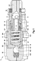
- Fig. 1 to 3 show a conventional piston pump which is used in a vehicle brake system. How out Fig. 1 to 3 1, a conventional piston pump 1 comprises a piston assembly 2 which has a first piston element 2.1 with a sealing element 13 and a second piston element 2.2, an inlet valve 5, an outlet valve 6 and a cylinder 8.
- the inlet valve 5 is designed as a check valve and comprises a Cage element 11, in which an inlet valve spring 5.2 and an inlet valve sealing element 5.3 is arranged, wherein the inlet sealing element 5.3, for example, is designed as a sealing disc which can sealingly cooperate with a corresponding inlet valve seat 5.1, which is arranged on the second piston element 2.2, wherein the second piston element 2.2 frictionally is connected to the cage element 11.
- the outlet valve 6 is likewise designed as a spring-loaded check valve and arranged in a cover element 12.
- the exhaust valve 6 is opened when a pressure in a compression chamber 8.1 is greater than a spring force of an exhaust valve spring 6.3 acting on an exhaust valve member 6.2 of the exhaust valve 6, whereby the exhaust valve sealing member 6.2 is pressed from a arranged at an outlet 8.3 of the cylinder 8 exhaust valve seat 6.1.
- a restoring force F2 arranged in the compression chamber 8.1 and guided by a cylinder wall 8.4 return spring 10, for example, as a spiral spring is executed with ground end applications and is supported on a cylinder bottom 8.2 and on a cage member 11, against the cage member 11 of the inlet valve 5 and thus acts against the second piston member 2.2 to move the piston assembly 2 again in the direction of top dead center.
- valve element designed as a second piston member 22 must be made as a stable component, preferably as a metal component, and can only be weakened conditionally by suction holes in the form of transverse bores.
- the transverse bores 3 are therefore incorporated in the first piston element 2.1, resulting in a relatively longer than longitudinal bore 4 executed inlet area.
- a piston pump according to the generic features of claim 1 is further known from the DE 197 47 850 A1 ,
- This piston pump has a piston which is designed as a composite part and which has a steel core, which is encapsulated with a sliding jacket made of plastic at its periphery.
- a conical valve seat is formed at the end of a blind hole within the sliding skirt made of plastic. The blind hole is traversed by a transverse hole above the valve seat. Blind hole and transverse hole are relatively long and have a small inner diameter in relation to the outer dimensions of the sliding shell.
- a second piston member of a piston assembly is designed as a sleeve made of a wear-resistant material that receives axially acting force components, wherein the inlet valve seat is disposed on a bending edge of the second piston element designed as a sleeve , and wherein in the second piston element at least one corresponding with a longitudinal bore transverse bore is introduced.
- the designed as a sleeve second piston element can be made extremely inexpensive.
- the inlet channel designed as a longitudinal bore can be dimensioned so extremely short and large that the flow resistance is advantageously reduced to a minimum.
- the piston pump according to the invention can be filled faster and thereby a better pressure build-up dynamics is achieved, which is particularly relevant in a design as a stepped piston pump.
- the invention enables a cost-effective and space-optimized piston pump, which can be used for example as a return pump in a brake system for a vehicle.
- the second piston element designed as a sleeve can be produced in a deep-drawing method or a cold-striking method, wherein the at least one transverse bore is punched or drilled in the second piston element designed as a sleeve.
- a deep-drawn part can be omitted by a work hardening in the manufacturing process in an advantageous manner to a heat treatment.
- the intake valve seat does not need to be reworked. If necessary, the inlet valve seat arranged at the bending edge can be re-stamped to increase the tightness.
- a first piston element of the piston assembly can be designed, for example, as a cylindrical needle roller and is advantageously available as a mass-produced standard part. Since a transmission of the driving force of an eccentric is effected via a line contact on the first piston part designed as a solid metal needle roller, preferably as a steel needle roller, the wear can be reduced in an advantageous manner.
- the first piston element can, for example, be loosely coupled to the second piston element. Alternatively, the first piston element can be positively and / or non-positively coupled to the second piston element.
- the second piston element as a sleeve which can be produced by deep-drawing or cold-striking process, it is possible to realize the intake valve seat, a positive connection for fixed coupling with the first piston element and the at least one transverse bore and the corresponding longitudinal bore without machining.
- the piston assembly according to the invention can be performed in two stages by a corresponding embodiment of the second piston element designed as a sleeve and the coupling with the first piston element without costly Einsteckschleifen in a simple manner.
- a cage element has an elastic high-pressure sealing element, which is designed to receive radially acting force components and sealed by a radial sealing surface against a cylinder wall and axially sealed by an axial sealing surface against a shoulder of the second piston element designed as a sleeve. Since there is no frictional connection between the cage element with the high-pressure sealing element and the second piston element with the inlet valve seat, in contrast to the conventional piston pump, an assembly step is advantageously dispensed with in the production of the piston pump according to the invention.
- the cage element can be performed with the elastic high-pressure sealing element as plastic injection molded parts.
- the execution as a plastic injection molded parts allows advantageously a simple, cost-effective production of the device, with a complex shape design is possible.
- the radial sealing surface is formed, for example, by a pressure-related expansion of the high-pressure sealing element.
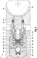
- a piston pump 21 according to the invention which can be used as a return pump in a vehicle brake system, comprises essentially the same components as those under reference Fig. 1 to 3 Therefore, to avoid repetition of text only the essential differences between the piston pump according to the invention and the conventional piston pump 1 according to here Fig. 1 to 3 described in detail.
- the piston pump according to the invention comprises an improved piston assembly in combination with a high-pressure sealing element.
- the piston pump 21 comprises, analogously to the conventional piston pump 1, a piston assembly 22, an inlet valve 25, an outlet valve 26 and a cylinder 28.
- a first piston element 22.1 of the piston assembly 22 is designed as a cylindrical needle roller, and a second piston element 22.2 of the piston assembly 22 is produced as a sleeve made of a wear-resistant material in a deep-drawing process or a cold-striking process.
- the inlet valve 25 of the piston pump 21 is designed as a check valve analogous to the conventional piston pump 1, a cage member 31, in which an inlet valve spring 25.2 and an inlet valve sealing element 25.3, which is designed for example as a sealing ball, and a corresponding inlet valve seat 25.1, which at a Bending edge of the second piston element 22.2 designed as a sleeve is arranged, wherein in the second piston element 22.2 more with a longitudinal bore 24 corresponding transverse bores 23 are punched or drilled. To improve the tightness of the arranged at the bending edge inlet valve seat 25.1 can be re-stamped.
- the inlet valve sealing element 25.3 is pressed sealingly into the corresponding inlet valve seat 25.1 by a spring force of the inlet valve spring 25.2.
- the cage element 31 of the piston pump 21 according to the invention on an elastic high-pressure sealing element 31.1, which is designed to receive radially acting force components F3 and sealed by a radial sealing surface 31.3 against a cylinder wall 28.4 and an axial sealing surface 31.5 against a shoulder 22.3 of the second piston member 22.2 axially seal, which rests against the axial sealing surface 31.5.
- the second piston element 22.2 only absorbs the axially acting force components F1 and F2, so that the longitudinal bore 24 and the transverse bores 23 corresponding to the longitudinal bore 24 can be introduced without loss of strength in the second piston element 22.2.
- the cage member 31 are executed with the elastic high-pressure sealing element 31.1 as plastic injection parts, which advantageously allows a simple, inexpensive production of the device, with a complex shape design is possible.
- the first piston element 22. 1 is firmly coupled to the second piston element 22. 2 and has a sealing element 33.
- the first piston element 22.1 can be loosely coupled to the second piston element 22.2.
- the inventive design of the piston assembly 22 in combination with the high-pressure sealing element 31.1 allows an extreme cost reduction of the piston pump 21 and a simple assembly.
- a longitudinal bore 24 running inlet channel are so extremely short and large dimensions that the flow resistance can be advantageously reduced to a minimum. This has the consequence that the piston pump 21 according to the invention can be filled faster and thereby a better pressure build-up dynamics is achieved.
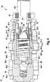
- the outlet valve 26 is also designed as a spring-loaded check valve and arranged in a cover member 32.
- the exhaust valve 26 is opened when a pressure in a compression chamber 28.1 is greater than a spring force of an exhaust valve spring 26.3 acting on an exhaust valve 26.2 of the exhaust valve 26, thereby forcing the exhaust valve 26.2 out of an exhaust valve seat 26.1 located on an exhaust port 28.3 of the cylinder 28.
- the piston assembly 22 is longitudinally movably guided in the cylinder 28 with the inlet valve 25, during a suction stroke of the piston assembly 22 fluid being sucked in radially via a filter sleeve 29 through the transverse bores 23 in the second piston element 22.2 and via the longitudinal bore 24 corresponding to the transverse bores 23 is guided through the open inlet valve 25 in the compression space 28.1.
- the direction of movement of the piston group 22 reverses, so that the second piston element 22.2 with the inlet valve seat 25.1 is pressed sealingly against the inlet valve sealing element 25.3 via the first piston element 22.1 driven by an eccentric, not shown, and the inlet valve 25 is closed.
- the direction of movement of the piston group 22 is reversed again, so that the exhaust valve 26 closes again and the intake stroke starts again, with a restoring force F2 arranged in the compression space 28.1 return spring 30, which is designed for example as a spiral spring and on a Supported cylinder bottom 28.2, presses against a radial support portion 31.4, which is arranged on the high-pressure sealing element 31.1.
- the restoring force F2 acts via the high-pressure sealing element 31.1 and the axial sealing surface 31.5 axially on the shoulder 22.3 of the second piston element 22.2, whereby the piston assembly 22 again in the direction top dead center is moved.
- the elastic high-pressure sealing element 31.1 is arranged between the metallic return spring 30 and the second piston element 22.2 made of a wear-resistant and thus hard material, the radial sealing surface 31.3 is widened due to pressure, so that the high-pressure sealing element 31.1 rests sealingly against the cylinder wall 28.4 with its complete radial outer diameter .
- the high-pressure sealing element 31.1 seals radially against the cylinder wall 28.4 via the radial sealing surface 31.3 and against the shoulder 22.3 of the second piston element 22.2 through the axial sealing surface 31.5.
- the inlet valve sealing element 25.3 seals axially against the inlet valve seat 25.1 in the second piston element 22.2.
- the piston pump according to the invention advantageously comprises many components that can be manufactured very easily and inexpensively.
- the flow resistance can advantageously be reduced to a minimum, whereby the piston pump according to the invention filled faster and thereby a better pressure build-up dynamics can be achieved.
- the invention enables a cost-effective and space-optimized piston pump, which can be used for example as a return pump in a brake system for a vehicle.
Landscapes
- Engineering & Computer Science (AREA)
- Mechanical Engineering (AREA)
- General Engineering & Computer Science (AREA)
- Physics & Mathematics (AREA)
- Fluid Mechanics (AREA)
- Transportation (AREA)
- Details Of Reciprocating Pumps (AREA)
Claims (10)
- Pompe à piston comprenant un module de piston (22) qui comprend un premier élément de piston (22.1), un deuxième élément de piston (22.2), au moins un alésage transversal (23) et un alésage longitudinal (24) correspondant à l'au moins un alésage transversal (23), un cylindre (28) dans lequel est guidé de manière déplaçable longitudinalement le module de piston (22), et une soupape d'admission (25) qui comprend un élément de cage (31) dans lequel est disposé un ressort de soupape d'admission (25.2) et un élément d'étanchéité de soupape d'admission (25.3), et un siège de soupape d'admission (25.1) correspondant qui est disposé au niveau du deuxième élément de piston (22.1), l'élément d'étanchéité de soupape d'admission (25.3) pouvant être pressé par une force de ressort du ressort de soupape d'admission (25.2) de manière hermétique dans le siège de soupape d'admission (25.1) correspondant, afin de fermer l'alésage longitudinal (24), du fluide pouvant être aspiré par le biais de l'au moins un alésage transversal (23) disposé dans le module de piston (22), lequel peut être conduit à travers l'alésage longitudinal (24) par le biais de la soupape d'admission (25) dans un espace de compression (28.1), dans lequel est disposé un ressort de rappel (30) pour le module de piston (22), caractérisé en ce que le deuxième élément de piston (22.2) est réalisé sous forme de douille en un matériau résistant à l'usure qui reçoit des composantes de force agissant axialement, le siège de soupape d'admission (25.1) étant disposé au niveau d'une arête de flexion du deuxième élément de piston (22.2) réalisé sous forme de douille, l'au moins un alésage transversal (23) correspondant à l'alésage longitudinal (24) étant réalisé dans le deuxième élément de piston (22.1).
- Pompe à piston selon la revendication 1, caractérisée en ce que le deuxième élément de piston (22.2) réalisé sous forme de douille peut être fabriqué par un procédé d'emboutissage profond ou un procédé de matriçage à froid, l'au moins un alésage transversal (23) étant estampé ou percé dans le deuxième élément de piston (22.2) réalisé sous forme de douille.
- Pompe à piston selon la revendication 1 ou 2, caractérisée en ce que le siège de soupape d'admission (25.1) disposé au niveau de l'arête de flexion est gaufré ultérieurement.
- Pompe à piston selon l'une quelconque des revendications 1 à 3, caractérisée en ce que le premier élément de piston (22.1) est réalisé sous forme de cage à aiguilles cylindrique.
- Pompe à piston selon l'une quelconque des revendications 1 à 4, caractérisée en ce que le premier élément de pompe (22.1) est accouplé de manière lâche au deuxième élément de piston (22.1).
- Pompe à piston selon l'une quelconque des revendications 1 à 4, caractérisée en ce que le premier élément de piston (22.1) est accouplé par engagement par correspondance de formes et/ou par force au deuxième élément de piston (22.1).
- Pompe à piston selon l'une quelconque des revendications 1 à 6, caractérisée en ce que l'élément de cage (31) présente un élément d'étanchéité haute pression élastique (31.1) qui est réalisé de manière à recevoir les composantes de force agissant radialement et à réaliser l'étanchéité par le biais d'une surface d'étanchéité radiale (31.3) par rapport à une paroi de cylindre (28.4) et à réaliser une étanchéité axiale par le biais d'une surface d'étanchéité axiale (31.5) par rapport à un épaulement (22.3) du deuxième élément de piston (22.1) réalisé sous forme de douille.
- Pompe à piston selon la revendication 7, caractérisée en ce que la surface d'étanchéité radiale (31.3) peut être formée par un élargissement, dû à la pression, de l'élément d'étanchéité haute pression (31.1).
- Pompe à piston selon la revendication 7 ou 8, caractérisée en ce que l'élément de cage (31) est réalisé sous forme de pièce moulée par injection de plastique avec l'élément d'étanchéité haute pression élastique (31.1).
- Système de frein pour un véhicule, caractérisé par une pompe de refoulement, qui est réalisée sous forme de pompe de récupération (21) selon l'une quelconque des revendications 1 à 9.
Applications Claiming Priority (2)
| Application Number | Priority Date | Filing Date | Title |
|---|---|---|---|
| DE102007047418A DE102007047418A1 (de) | 2007-10-04 | 2007-10-04 | Kolbenpumpe zur Förderung eines Fluids und zugehöriges Bremssystem |
| PCT/EP2008/062451 WO2009043731A1 (fr) | 2007-10-04 | 2008-09-18 | Pompe à piston destinée au refoulement d'un fluide et système de freinage associé |
Publications (2)
| Publication Number | Publication Date |
|---|---|
| EP2205865A1 EP2205865A1 (fr) | 2010-07-14 |
| EP2205865B1 true EP2205865B1 (fr) | 2017-01-25 |
Family
ID=40139231
Family Applications (1)
| Application Number | Title | Priority Date | Filing Date |
|---|---|---|---|
| EP08804390.6A Active EP2205865B1 (fr) | 2007-10-04 | 2008-09-18 | Pompe à piston destinée au refoulement d'un fluide et système de freinage associé |
Country Status (5)
| Country | Link |
|---|---|
| US (1) | US8845038B2 (fr) |
| EP (1) | EP2205865B1 (fr) |
| CN (1) | CN101809285A (fr) |
| DE (1) | DE102007047418A1 (fr) |
| WO (1) | WO2009043731A1 (fr) |
Families Citing this family (11)
| Publication number | Priority date | Publication date | Assignee | Title |
|---|---|---|---|---|
| DE102010001237B4 (de) | 2009-12-01 | 2024-09-12 | Continental Automotive Technologies GmbH | Verfahren zur Montage eines Federanschlags einer Kolbenrückstellfeder mittels eines Rastmechanismus an einem Pumpenkolben einer Kolbenpumpe |
| DE102010040819A1 (de) | 2010-09-15 | 2012-03-15 | Robert Bosch Gmbh | Verfahren zur Herstellung einer Kolbenpumpe und Kolbenpumpe |
| DE102010062174A1 (de) * | 2010-11-30 | 2012-05-31 | Robert Bosch Gmbh | Ventil, insbesondere ein Auslassventil einer hydraulischen Kolbenpumpe |
| DE102010064114B4 (de) * | 2010-12-23 | 2021-07-29 | Robert Bosch Gmbh | Pumpe mit einer Drossel |
| DE102011107761A1 (de) | 2011-07-15 | 2013-01-17 | Thomas Magnete Gmbh | Dosierpumpe |
| DE102011079864A1 (de) | 2011-07-26 | 2013-01-31 | Robert Bosch Gmbh | Kolbenpumpe |
| DE102012219621A1 (de) * | 2012-10-26 | 2014-04-30 | Robert Bosch Gmbh | Kolbenpumpe |
| WO2018183154A1 (fr) * | 2017-03-27 | 2018-10-04 | Karcher North America, Inc. | Pompe à piston creux |
| DE102021208531B3 (de) * | 2021-08-05 | 2022-11-10 | Trelleborg Sealing Solutions Germany Gmbh | Geberkolben, hydraulische Fahrzeugbremse und Verfahren zum Herstellen des Geberkolbens |
| US11781541B2 (en) * | 2021-09-29 | 2023-10-10 | Chipmast Autotronix Co., Ltd. | Oil-scavenge pump and method for assembling the same |
| US11668291B2 (en) * | 2021-09-29 | 2023-06-06 | Chipmast Autotronix Co., Ltd. | Oil-scavenge pump and method for assembling the same |
Family Cites Families (9)
| Publication number | Priority date | Publication date | Assignee | Title |
|---|---|---|---|---|
| DE9319462U1 (de) * | 1993-12-17 | 1995-04-27 | Lucas Industries Public Limited Company, Solihull, West Midlands | Kolbenpumpe zum Fördern von Hydraulikflüssigkeit in einer blockiergeschützten Fahrzeugbremsanlage |
| DE19747936A1 (de) * | 1997-07-30 | 1999-02-04 | Bosch Gmbh Robert | Kolbenpumpe |
| WO1999006697A1 (fr) * | 1997-07-30 | 1999-02-11 | Robert Bosch Gmbh | Piston tubulaire produit par formage a froid et bouchon de fermeture pour une pompe a pistons radiaux |
| EP0931218A1 (fr) * | 1997-07-30 | 1999-07-28 | Robert Bosch Gmbh | Pompe a piston |
| DE19747850A1 (de) | 1997-07-30 | 1999-02-04 | Bosch Gmbh Robert | Kolbenpumpe |
| DE19820902A1 (de) * | 1998-05-09 | 1999-11-11 | Bosch Gmbh Robert | Kolbenpumpe |
| DE102006028638A1 (de) * | 2006-06-22 | 2008-01-03 | Robert Bosch Gmbh | Kolbenpumpe |
| JP4946637B2 (ja) * | 2006-08-07 | 2012-06-06 | 株式会社アドヴィックス | ピストンポンプ |
| DE102006051589A1 (de) * | 2006-11-02 | 2008-05-08 | Robert Bosch Gmbh | Kolbenpumpe |
-
2007
- 2007-10-04 DE DE102007047418A patent/DE102007047418A1/de not_active Ceased
-
2008
- 2008-09-18 US US12/680,962 patent/US8845038B2/en active Active
- 2008-09-18 WO PCT/EP2008/062451 patent/WO2009043731A1/fr active Application Filing
- 2008-09-18 CN CN200880109745.4A patent/CN101809285A/zh active Pending
- 2008-09-18 EP EP08804390.6A patent/EP2205865B1/fr active Active
Non-Patent Citations (1)
| Title |
|---|
| None * |
Also Published As
| Publication number | Publication date |
|---|---|
| CN101809285A (zh) | 2010-08-18 |
| US20100232998A1 (en) | 2010-09-16 |
| US8845038B2 (en) | 2014-09-30 |
| EP2205865A1 (fr) | 2010-07-14 |
| WO2009043731A1 (fr) | 2009-04-09 |
| DE102007047418A1 (de) | 2009-04-23 |
Similar Documents
| Publication | Publication Date | Title |
|---|---|---|
| EP2205865B1 (fr) | Pompe à piston destinée au refoulement d'un fluide et système de freinage associé | |
| EP0935719B1 (fr) | Clapet anti-retour destine notamment a une pompe a piston | |
| EP1185794B1 (fr) | Pompe a piston | |
| EP2205866A1 (fr) | Pompe à piston destinée au refoulement d'un fluide et système de freinage associé | |
| EP2049794B1 (fr) | Dispositif d'étancheité et de guidage pour un piston d'une pompe à piston | |
| DE19800500A1 (de) | Kolbenpumpe | |
| DE19732817A1 (de) | Kolbenpumpe | |
| WO2000073658A1 (fr) | Pompe a piston | |
| EP0931218A1 (fr) | Pompe a piston | |
| EP2205867B1 (fr) | Pompe à piston destinée au refoulement d'un fluide et système de freinage associé | |
| DE19750851A1 (de) | Kolbenpumpe | |
| DE19928913A1 (de) | Kolbenpumpe | |
| DE102005042197A1 (de) | Kolbenpumpe mit verbessertem Kolben | |
| WO2007147693A2 (fr) | Pompe à piston | |
| DE102006027555A1 (de) | Kolbenpumpe mit reduziertem Geräusch | |
| WO2007137892A1 (fr) | Pompe À piston | |
| DE19831450A1 (de) | Kolbenpumpe | |
| EP2086805B1 (fr) | Pompe à piston | |
| DE19918124A1 (de) | Kolbenpumpe | |
| DE102006048903A1 (de) | Pumpe für ein Fahrzeugbremssystem mit einem Ventil | |
| EP1926909B1 (fr) | Pompe a piston a espace mort reduit | |
| DE19809592B4 (de) | Kolbenpumpe | |
| DE10019403A1 (de) | Rückschlagventil für eine Kolbenpumpe | |
| DE102019207686A1 (de) | Hydroaggregat, insbesondere zur Versorgung eines Bremskreises einer Fahrzeugbremsanlage mit Druckmittel unter Bremsdruck | |
| DE19833840A1 (de) | Kolbenpumpe |
Legal Events
| Date | Code | Title | Description |
|---|---|---|---|
| PUAI | Public reference made under article 153(3) epc to a published international application that has entered the european phase |
Free format text: ORIGINAL CODE: 0009012 |
|
| 17P | Request for examination filed |
Effective date: 20100504 |
|
| AK | Designated contracting states |
Kind code of ref document: A1 Designated state(s): AT BE BG CH CY CZ DE DK EE ES FI FR GB GR HR HU IE IS IT LI LT LU LV MC MT NL NO PL PT RO SE SI SK TR |
|
| AX | Request for extension of the european patent |
Extension state: AL BA MK RS |
|
| DAX | Request for extension of the european patent (deleted) | ||
| GRAP | Despatch of communication of intention to grant a patent |
Free format text: ORIGINAL CODE: EPIDOSNIGR1 |
|
| RIC1 | Information provided on ipc code assigned before grant |
Ipc: F04B 1/04 20060101AFI20161007BHEP Ipc: B60T 8/40 20060101ALI20161007BHEP Ipc: F04B 53/10 20060101ALI20161007BHEP |
|
| INTG | Intention to grant announced |
Effective date: 20161103 |
|
| GRAS | Grant fee paid |
Free format text: ORIGINAL CODE: EPIDOSNIGR3 |
|
| GRAA | (expected) grant |
Free format text: ORIGINAL CODE: 0009210 |
|
| AK | Designated contracting states |
Kind code of ref document: B1 Designated state(s): AT BE BG CH CY CZ DE DK EE ES FI FR GB GR HR HU IE IS IT LI LT LU LV MC MT NL NO PL PT RO SE SI SK TR |
|
| REG | Reference to a national code |
Ref country code: GB Ref legal event code: FG4D Free format text: NOT ENGLISH |
|
| REG | Reference to a national code |
Ref country code: CH Ref legal event code: EP |
|
| REG | Reference to a national code |
Ref country code: AT Ref legal event code: REF Ref document number: 864320 Country of ref document: AT Kind code of ref document: T Effective date: 20170215 |
|
| REG | Reference to a national code |
Ref country code: IE Ref legal event code: FG4D Free format text: LANGUAGE OF EP DOCUMENT: GERMAN |
|
| REG | Reference to a national code |
Ref country code: DE Ref legal event code: R096 Ref document number: 502008015000 Country of ref document: DE |
|
| REG | Reference to a national code |
Ref country code: LT Ref legal event code: MG4D |
|
| REG | Reference to a national code |
Ref country code: NL Ref legal event code: MP Effective date: 20170125 |
|
| PG25 | Lapsed in a contracting state [announced via postgrant information from national office to epo] |
Ref country code: NL Free format text: LAPSE BECAUSE OF FAILURE TO SUBMIT A TRANSLATION OF THE DESCRIPTION OR TO PAY THE FEE WITHIN THE PRESCRIBED TIME-LIMIT Effective date: 20170125 |
|
| PG25 | Lapsed in a contracting state [announced via postgrant information from national office to epo] |
Ref country code: LT Free format text: LAPSE BECAUSE OF FAILURE TO SUBMIT A TRANSLATION OF THE DESCRIPTION OR TO PAY THE FEE WITHIN THE PRESCRIBED TIME-LIMIT Effective date: 20170125 Ref country code: FI Free format text: LAPSE BECAUSE OF FAILURE TO SUBMIT A TRANSLATION OF THE DESCRIPTION OR TO PAY THE FEE WITHIN THE PRESCRIBED TIME-LIMIT Effective date: 20170125 Ref country code: GR Free format text: LAPSE BECAUSE OF FAILURE TO SUBMIT A TRANSLATION OF THE DESCRIPTION OR TO PAY THE FEE WITHIN THE PRESCRIBED TIME-LIMIT Effective date: 20170426 Ref country code: IS Free format text: LAPSE BECAUSE OF FAILURE TO SUBMIT A TRANSLATION OF THE DESCRIPTION OR TO PAY THE FEE WITHIN THE PRESCRIBED TIME-LIMIT Effective date: 20170525 Ref country code: HR Free format text: LAPSE BECAUSE OF FAILURE TO SUBMIT A TRANSLATION OF THE DESCRIPTION OR TO PAY THE FEE WITHIN THE PRESCRIBED TIME-LIMIT Effective date: 20170125 Ref country code: NO Free format text: LAPSE BECAUSE OF FAILURE TO SUBMIT A TRANSLATION OF THE DESCRIPTION OR TO PAY THE FEE WITHIN THE PRESCRIBED TIME-LIMIT Effective date: 20170425 |
|
| PG25 | Lapsed in a contracting state [announced via postgrant information from national office to epo] |
Ref country code: BG Free format text: LAPSE BECAUSE OF FAILURE TO SUBMIT A TRANSLATION OF THE DESCRIPTION OR TO PAY THE FEE WITHIN THE PRESCRIBED TIME-LIMIT Effective date: 20170425 Ref country code: SE Free format text: LAPSE BECAUSE OF FAILURE TO SUBMIT A TRANSLATION OF THE DESCRIPTION OR TO PAY THE FEE WITHIN THE PRESCRIBED TIME-LIMIT Effective date: 20170125 Ref country code: ES Free format text: LAPSE BECAUSE OF FAILURE TO SUBMIT A TRANSLATION OF THE DESCRIPTION OR TO PAY THE FEE WITHIN THE PRESCRIBED TIME-LIMIT Effective date: 20170125 Ref country code: PL Free format text: LAPSE BECAUSE OF FAILURE TO SUBMIT A TRANSLATION OF THE DESCRIPTION OR TO PAY THE FEE WITHIN THE PRESCRIBED TIME-LIMIT Effective date: 20170125 Ref country code: LV Free format text: LAPSE BECAUSE OF FAILURE TO SUBMIT A TRANSLATION OF THE DESCRIPTION OR TO PAY THE FEE WITHIN THE PRESCRIBED TIME-LIMIT Effective date: 20170125 Ref country code: PT Free format text: LAPSE BECAUSE OF FAILURE TO SUBMIT A TRANSLATION OF THE DESCRIPTION OR TO PAY THE FEE WITHIN THE PRESCRIBED TIME-LIMIT Effective date: 20170525 |
|
| REG | Reference to a national code |
Ref country code: FR Ref legal event code: PLFP Year of fee payment: 10 |
|
| REG | Reference to a national code |
Ref country code: DE Ref legal event code: R097 Ref document number: 502008015000 Country of ref document: DE |
|
| PG25 | Lapsed in a contracting state [announced via postgrant information from national office to epo] |
Ref country code: CZ Free format text: LAPSE BECAUSE OF FAILURE TO SUBMIT A TRANSLATION OF THE DESCRIPTION OR TO PAY THE FEE WITHIN THE PRESCRIBED TIME-LIMIT Effective date: 20170125 Ref country code: EE Free format text: LAPSE BECAUSE OF FAILURE TO SUBMIT A TRANSLATION OF THE DESCRIPTION OR TO PAY THE FEE WITHIN THE PRESCRIBED TIME-LIMIT Effective date: 20170125 Ref country code: RO Free format text: LAPSE BECAUSE OF FAILURE TO SUBMIT A TRANSLATION OF THE DESCRIPTION OR TO PAY THE FEE WITHIN THE PRESCRIBED TIME-LIMIT Effective date: 20170125 Ref country code: SK Free format text: LAPSE BECAUSE OF FAILURE TO SUBMIT A TRANSLATION OF THE DESCRIPTION OR TO PAY THE FEE WITHIN THE PRESCRIBED TIME-LIMIT Effective date: 20170125 Ref country code: IT Free format text: LAPSE BECAUSE OF FAILURE TO SUBMIT A TRANSLATION OF THE DESCRIPTION OR TO PAY THE FEE WITHIN THE PRESCRIBED TIME-LIMIT Effective date: 20170125 |
|
| PG25 | Lapsed in a contracting state [announced via postgrant information from national office to epo] |
Ref country code: DK Free format text: LAPSE BECAUSE OF FAILURE TO SUBMIT A TRANSLATION OF THE DESCRIPTION OR TO PAY THE FEE WITHIN THE PRESCRIBED TIME-LIMIT Effective date: 20170125 |
|
| PLBE | No opposition filed within time limit |
Free format text: ORIGINAL CODE: 0009261 |
|
| STAA | Information on the status of an ep patent application or granted ep patent |
Free format text: STATUS: NO OPPOSITION FILED WITHIN TIME LIMIT |
|
| 26N | No opposition filed |
Effective date: 20171026 |
|
| PG25 | Lapsed in a contracting state [announced via postgrant information from national office to epo] |
Ref country code: SI Free format text: LAPSE BECAUSE OF FAILURE TO SUBMIT A TRANSLATION OF THE DESCRIPTION OR TO PAY THE FEE WITHIN THE PRESCRIBED TIME-LIMIT Effective date: 20170125 |
|
| REG | Reference to a national code |
Ref country code: CH Ref legal event code: PL |
|
| PG25 | Lapsed in a contracting state [announced via postgrant information from national office to epo] |
Ref country code: MC Free format text: LAPSE BECAUSE OF FAILURE TO SUBMIT A TRANSLATION OF THE DESCRIPTION OR TO PAY THE FEE WITHIN THE PRESCRIBED TIME-LIMIT Effective date: 20170125 |
|
| REG | Reference to a national code |
Ref country code: IE Ref legal event code: MM4A |
|
| REG | Reference to a national code |
Ref country code: BE Ref legal event code: MM Effective date: 20170930 |
|
| PG25 | Lapsed in a contracting state [announced via postgrant information from national office to epo] |
Ref country code: LU Free format text: LAPSE BECAUSE OF NON-PAYMENT OF DUE FEES Effective date: 20170918 |
|
| PG25 | Lapsed in a contracting state [announced via postgrant information from national office to epo] |
Ref country code: CH Free format text: LAPSE BECAUSE OF NON-PAYMENT OF DUE FEES Effective date: 20170930 Ref country code: LI Free format text: LAPSE BECAUSE OF NON-PAYMENT OF DUE FEES Effective date: 20170930 Ref country code: IE Free format text: LAPSE BECAUSE OF NON-PAYMENT OF DUE FEES Effective date: 20170918 |
|
| PG25 | Lapsed in a contracting state [announced via postgrant information from national office to epo] |
Ref country code: BE Free format text: LAPSE BECAUSE OF NON-PAYMENT OF DUE FEES Effective date: 20170930 |
|
| REG | Reference to a national code |
Ref country code: FR Ref legal event code: PLFP Year of fee payment: 11 |
|
| PG25 | Lapsed in a contracting state [announced via postgrant information from national office to epo] |
Ref country code: MT Free format text: LAPSE BECAUSE OF FAILURE TO SUBMIT A TRANSLATION OF THE DESCRIPTION OR TO PAY THE FEE WITHIN THE PRESCRIBED TIME-LIMIT Effective date: 20170125 |
|
| REG | Reference to a national code |
Ref country code: AT Ref legal event code: MM01 Ref document number: 864320 Country of ref document: AT Kind code of ref document: T Effective date: 20170918 |
|
| PG25 | Lapsed in a contracting state [announced via postgrant information from national office to epo] |
Ref country code: AT Free format text: LAPSE BECAUSE OF NON-PAYMENT OF DUE FEES Effective date: 20170918 |
|
| PG25 | Lapsed in a contracting state [announced via postgrant information from national office to epo] |
Ref country code: HU Free format text: LAPSE BECAUSE OF FAILURE TO SUBMIT A TRANSLATION OF THE DESCRIPTION OR TO PAY THE FEE WITHIN THE PRESCRIBED TIME-LIMIT; INVALID AB INITIO Effective date: 20080918 |
|
| PG25 | Lapsed in a contracting state [announced via postgrant information from national office to epo] |
Ref country code: CY Free format text: LAPSE BECAUSE OF NON-PAYMENT OF DUE FEES Effective date: 20170125 |
|
| PGFP | Annual fee paid to national office [announced via postgrant information from national office to epo] |
Ref country code: GB Payment date: 20190924 Year of fee payment: 12 |
|
| PG25 | Lapsed in a contracting state [announced via postgrant information from national office to epo] |
Ref country code: TR Free format text: LAPSE BECAUSE OF FAILURE TO SUBMIT A TRANSLATION OF THE DESCRIPTION OR TO PAY THE FEE WITHIN THE PRESCRIBED TIME-LIMIT Effective date: 20170125 |
|
| GBPC | Gb: european patent ceased through non-payment of renewal fee |
Effective date: 20200918 |
|
| PG25 | Lapsed in a contracting state [announced via postgrant information from national office to epo] |
Ref country code: GB Free format text: LAPSE BECAUSE OF NON-PAYMENT OF DUE FEES Effective date: 20200918 |
|
| PGFP | Annual fee paid to national office [announced via postgrant information from national office to epo] |
Ref country code: FR Payment date: 20230918 Year of fee payment: 16 |
|
| PGFP | Annual fee paid to national office [announced via postgrant information from national office to epo] |
Ref country code: DE Payment date: 20231124 Year of fee payment: 16 |