EP2205002A1 - Spectral characteristic correction device and spectral characteristic correction method - Google Patents
Spectral characteristic correction device and spectral characteristic correction method Download PDFInfo
- Publication number
- EP2205002A1 EP2205002A1 EP08838577A EP08838577A EP2205002A1 EP 2205002 A1 EP2205002 A1 EP 2205002A1 EP 08838577 A EP08838577 A EP 08838577A EP 08838577 A EP08838577 A EP 08838577A EP 2205002 A1 EP2205002 A1 EP 2205002A1
- Authority
- EP
- European Patent Office
- Prior art keywords
- spectral characteristic
- correction
- color signal
- correcting
- calculating
- Prior art date
- Legal status (The legal status is an assumption and is not a legal conclusion. Google has not performed a legal analysis and makes no representation as to the accuracy of the status listed.)
- Withdrawn
Links
Images


Classifications
-
- H—ELECTRICITY
- H04—ELECTRIC COMMUNICATION TECHNIQUE
- H04N—PICTORIAL COMMUNICATION, e.g. TELEVISION
- H04N23/00—Cameras or camera modules comprising electronic image sensors; Control thereof
- H04N23/10—Cameras or camera modules comprising electronic image sensors; Control thereof for generating image signals from different wavelengths
- H04N23/125—Colour sequential image capture, e.g. using a colour wheel
-
- H—ELECTRICITY
- H04—ELECTRIC COMMUNICATION TECHNIQUE
- H04N—PICTORIAL COMMUNICATION, e.g. TELEVISION
- H04N23/00—Cameras or camera modules comprising electronic image sensors; Control thereof
- H04N23/80—Camera processing pipelines; Components thereof
- H04N23/84—Camera processing pipelines; Components thereof for processing colour signals
- H04N23/843—Demosaicing, e.g. interpolating colour pixel values
-
- H—ELECTRICITY
- H04—ELECTRIC COMMUNICATION TECHNIQUE
- H04N—PICTORIAL COMMUNICATION, e.g. TELEVISION
- H04N25/00—Circuitry of solid-state image sensors [SSIS]; Control thereof
- H04N25/10—Circuitry of solid-state image sensors [SSIS]; Control thereof for transforming different wavelengths into image signals
- H04N25/11—Arrangement of colour filter arrays [CFA]; Filter mosaics
- H04N25/13—Arrangement of colour filter arrays [CFA]; Filter mosaics characterised by the spectral characteristics of the filter elements
- H04N25/134—Arrangement of colour filter arrays [CFA]; Filter mosaics characterised by the spectral characteristics of the filter elements based on three different wavelength filter elements
Definitions
- the present invention relates to a spectral characteristic correction apparatus and a spectral characteristic correction method for correcting spectral characteristics characterizing a color signal including multiple chrominance signals.
- color reproduction of a subject shot by an image pickup apparatus such as a digital camera in different environments can vary between the environments. In reality, color reproduction also can vary even when the same subject is shot in the same environment.
- Image pickup apparatuses are designed to pick up images by using an image pickup device equipped with a color filter, for example.
- Different types of image pickup devices have different characteristics, such as spectral characteristics, related to color reproduction. Characteristics of image pickup devices of the same type also can vary depending on materials and manufacturing processes of the image pickup devices or can change with time. The differences in characteristics result in color reproductions that vary from one image pickup apparatuses to another. Color reproduction is treated as one of important factors especially in medical fields. Differences in color production can inhibit medical diagnosis.
- Japanese Patent Application Laid-Open Publication No. 2001-358960 describes a technique that derives, on the basis of first and second spectral sensitivity distribution, a color correction coefficient for linearly converting a signal characterized by the first spectral sensitivity distribution to a signal characterized by the second spectral sensitivity distribution.
- Japanese Patent Application Laid-Open Publication No. 2005-117524 describes a technique in which a color chart is photographed for each of multiple image pickup devices and a color correction coefficient is derived such that image data of the photographed color charts agree with each other.
- the derived color correction coefficient depends on the number of colors on the color chart. Accordingly, it is not guaranteed that colors that are not on the color chart can be corrected with a high degree of precision. To correct an entire color gamut, a color chart with diverse colors needs to be provided. It is unrealistic to prepare and measure such a large-scale color chart.
- the present invention has been made in light of these circumstances and an object of the present invention is to provide a spectral characteristic correction apparatus and a spectral characteristic correction method capable of simply providing approximately the same color reproduction even with different image pickup devices.
- a spectral characteristic correction apparatus correcting a spectral characteristic characterizing a color signal including a plurality of chrominance signals, including: correction coefficient calculating means for calculating, on the basis of basic color signals corresponding to a plurality of basic colors and predetermined reference color signals corresponding to the basic color signals, a correction coefficient for performing correction for approximating the basic color signals to the reference color signals; and spectral characteristic correcting means for correcting a spectral characteristic characterizing the basic color signals by using the correction coefficient calculated by the correction coefficient calculating means.
- the correction coefficient calculating means is illustrated as a correction coefficient calculating unit 106 in Figs. 1 and 5 .
- the spectral characteristic correcting means is illustrated as a spectral characteristic correcting unit 107 in Figs. 1 and 8 .
- a spectral characteristic correction method for correcting a spectral characteristic characterizing a color signal including a plurality of chrominance signals, including: a correction coefficient calculating step of calculating, on the basis of basic color signals corresponding to a plurality of basic colors and predetermined reference color signals corresponding to the basic color signals, a correction coefficient for performing correction for approximating the basic color signals to the reference color signals; and a spectral characteristic correcting step of correcting a spectral characteristic characterizing the basic color signals by using the correction coefficient calculated by the correction coefficient calculating step.
- Figs. 1 through 11 illustrate a first embodiment of the present invention.
- Fig. 1 is a block diagram illustrating a configuration of a spectral characteristic correction apparatus having a function of an image pickup apparatus;
- Fig. 2 is a diagram illustrating a color chart;
- Fig. 3 is a graph illustrating spectral transmittances of color patches of the color chart;
- Fig. 4 is a diagram illustrating a configuration of a Bayer primary color filter;
- Fig. 5 is a block diagram illustrating a configuration of a correction coefficient calculating unit;
- Fig. 6 is a graph illustrating a spectral characteristic of a light source;
- Fig. 7 is a graph illustrating target spectral characteristics representing targeted color reproduction of an image pickup device;
- Fig. 1 is a block diagram illustrating a configuration of a spectral characteristic correction apparatus having a function of an image pickup apparatus
- Fig. 2 is a diagram illustrating a color chart
- Fig. 3 is
- FIG. 8 is a block diagram illustrating a configuration of a spectral characteristic correcting unit
- Fig. 9 is a block diagram illustrating a configuration of a conversion coefficient calculating unit
- Fig. 10 is a diagram illustrating a configuration of a rotary filter
- Fig. 11 is a flowchart illustrating a spectral characteristic correction process.
- the spectral characteristic correction apparatus includes a lens system 100, a CCD 101, an A/D conversion unit 102, a buffer 103, an interpolation unit 104, a signal processing unit 105, a correction coefficient calculating unit 106, a spectral characteristic correcting unit 107, a conversion coefficient calculating unit 108, an output unit 109, a control unit 110, and an external interface unit 111.
- the lens system 100 is designed to form an optical image of a subject on the CCD 101 and constitutes image pickup means.
- the CCD 101 is an image pickup device which photoelectrically converts an optical image formed through the lens system and outputs a video signal.
- the CCD 101 constitutes image pickup means.
- the CCD 101 is connected to the output unit 109 through the A/D conversion unit 102, the buffer 103, the interpolation unit 104, the signal processing unit 105, the correction coefficient calculating unit 106, the spectral characteristic correcting unit 107, and the conversion coefficient calculating unit 108, in this order.
- the external interface unit 111 is connected to the spectral characteristic correcting unit 107.
- the control unit 110 is bidirectionally connected to the A/D conversion unit 102, the interpolation unit 104, the signal processing unit 105, the correction coefficient calculating unit 106, the spectral characteristic correcting unit 107, the conversion coefficient calculating unit 108, the output unit 109, and the external interface unit 111.
- the A/D conversion unit 102 is designed to convert an analog video signal outputted from the CCD 101 to a digital video signal.
- the buffer 103 is designed to temporally store a digital video signal produced through conversion by the A/D conversion unit 102.
- the interpolation unit 104 is designed to apply well known interpolation processing, such as interpolation to a three signal including all of three color component signals for each pixel from a single signal including only one of three color component signals for each pixel, to a video signal transferred from the buffer 103.
- the signal processing unit 105 is designed to apply well known signal processing such as luminance correction to a video signal transferred from the interpolation unit 104.
- the correction coefficient calculating unit 106 is correction coefficient calculating means which calculates a correction coefficient on the basis of a video signal transferred from the signal processing unit 105, as will be described later.
- the spectral characteristic correcting unit 107 is spectral characteristic correcting means which corrects a spectral characteristic on the basis of a correction coefficient transferred from the correction coefficient calculating unit 106, as will be described later.
- the conversion coefficient calculating unit 108 is conversion coefficient calculating means which calculates a conversion coefficient on the basis of a corrected spectral characteristic transferred from the spectral characteristic correcting unit 107, as will be described later.
- the output unit 109 outputs a conversion coefficient transferred from the conversion coefficient calculating unit 108 and records the conversion coefficient on a recording medium such as a memory card.
- the control unit 110 which may be formed by a microcomputer, for example, centrally controls the entire spectral characteristic correction apparatus.
- the external interface unit 111 is an interface including a power switch, a shutter button, an input device for inputting information concerning a spectral characteristic and other information.
- a spectral characteristic of an image pickup device to be corrected (spectral characteristic of interest) is inputted through the input device of the external interface unit 111.
- a color chart 120 is placed perpendicularly to an optical axis of the lens system 100 in a position where an image of the color chart 120 can be picked up.
- the shutter button of the external interface unit 111 is pressed to photograph the color chart 120.
- the color chart 120 is a transmissive color chart on which multiple color patches that transmit only light in a predetermined particular narrow wavelength band are arranged. Since the wavelength band of the spectral transmittances of the color patches is narrowed, feature of the distribution profiles of spectral characteristics of the image pickup device can be extracted with a high degree of precision.
- 11 color patches having spectral transmittances O 1 to O 11 are arranged on the surface of the color chart 120 as depicted in Fig. 2 .
- the spectral transmittances O 1 to O 11 are depicted in Fig. 3 .
- the spectral characteristics O 1 to O 11 are such that peak wavelengths appear at intervals of 30 nm in the range of wavelengths of 400 nm to 700 nm. It is assumed that the distribution profile of spectral transmittance of each color patch is bell-shaped with a full width at half maximum (FWHM) of 30 nm.
- the FWHM of the color patches is not limited to 30 nm; color patches with any FWHM may be used.
- a light-box light source is placed at the rear of the color chart 120 and is caused to emit light. In this way, light is applied from behind the color chart 120 toward the lens system 100 and the CCD 101.
- an optical image of the color chart 120 is formed on the CCD 101 through the lens system 100.
- the CCD 101 photoelectrically converts the optical image and outputs a video signal. It is assumed in the present embodiment that the CCD 101 is a single-CCD equipped with a Bayer primary color filter.
- 2 ⁇ 2-pixel units are arranged on the Bayer primary color filter as depicted in Fig. 4 .
- each unit two G (green) pixels are diagonally placed and one R (red) pixel and one B (blue) pixel are diagonally placed in the remaining two pixels.
- a video signal from the CCD 101 is converted to a digital signal by the A/D conversion unit 102 and is temporarily stored in the buffer 103. Accordingly, the video signal stored in the buffer 103 through the A/D conversion unit 102 is an RGB signal (RGB Bayer signal) which provides only one of R, G, and B signals for one pixel.
- the RGB signal is transferred from the buffer 103 to the interpolation unit 104.
- the interpolation unit 104 performs well known interpolation processing to generate a three RGB signal (an RGB signal including all of R, G, and B signals for each pixel).
- the three RGB signal is transferred from the interpolation unit 104 to the signal processing unit 105.
- the signal processing unit 105 applies well known signal processing such as luminance correction to the RGB signal transferred from the interpolation unit 104.
- the video signal processed by the signal processing unit 105 is transferred to the correction coefficient calculating unit 106.
- the correction coefficient calculating unit 106 calculates a correction coefficient used for correcting a spectral characteristic, on the basis of the RGB signal obtained through the signal processing unit 105 and an internally stored, predetermined reference RGB signal for each of the color patches.
- the correction coefficient calculated by the correction coefficient calculating unit 106 is transferred to the spectral characteristic correcting unit 107.
- the spectral characteristic correcting unit 107 corrects a spectral characteristic of interest (a spectral characteristic to be corrected) on the basis of the correction coefficient calculated by the correction coefficient calculating unit 106. It is assumed here that the spectral characteristic of interest which is inputted through the external interface unit 111 as stated above is a spectral characteristic typical of a model of CCD 101. Specifically, a spectral characteristic stated in a catalog, for example, can be used. The typical spectral characteristic is not limited to one that stated in a catalog. For example, a spectral characteristic of one particular CCD that belongs to a given model may be actually measured and the measured spectral characteristic may be used. The spectral characteristic of interest corrected by the spectral characteristic correcting unit 107 is transferred to the conversion coefficient calculating unit 108.
- the conversion coefficient calculating unit 108 calculates a conversion coefficient for correcting a difference between the spectral characteristic of interest and the target spectral characteristic (a conversion coefficient for converting the spectral characteristic of interest to the target spectral characteristic).
- the conversion coefficient calculated by the conversion coefficient calculating unit 108 is transferred to the output unit 109.
- the output unit 109 records and stores the conversion coefficient obtained from the conversion coefficient calculating unit 108 on a recording medium such as a memory card.
- the correction coefficient calculating unit 106 includes a buffer 200, a signal calculating section 201 which is signal calculating means, a correction function calculating section 202 which is correction function calculating means, and a reference signal ROM 203.
- the signal processing unit 105 is connected to the buffer 200.
- the buffer 200 is connected to the signal calculating section 201.
- the signal calculating section201 is connected to the correction function calculating section 202.
- the reference signal ROM 203 is also connected to the correction function calculating section 202.
- the correction function calculating section 202 is connected to the spectral characteristic correcting unit 107.
- the control unit 110 is bidirectionally connected to the signal calculating section 201 and the correction function calculating section 202 to control these sections.
- An RGB signal is transferred from the signal processing unit 105 to the buffer 200, where the RGB signal is temporarily stored.
- the RGB signal stored in the buffer 200 is then transferred to the signal calculating section 201.
- the signal calculating section 201 calculates an average RGB signal (an average R signal, an average G signal and an average B signal) for each color patch on the color chart 120 as depicted in Figs. 2 and 3 from the RGB signal obtained through the buffer 200 (the average RGB signal is called basic RGB signal) and transfers the calculated basic RGB signal to the correction function calculating section 202.
- an average RGB signal an average R signal, an average G signal and an average B signal
- the correction function calculating section 202 reads a reference RGB signal for each color patch which has been stored in the reference signal ROM 203 in advance.
- the reference RGB signal is the sum of the products obtained for each wavelength component by multiplying a spectral characteristic of the light-box light source measured beforehand by a target spectral characteristic of the image pickup device (see Fig. 7 ), which represent targeted color reproduction, by a spectral transmittance of each color patch (see Fig. 3 ).
- the RGB signal is calculated according to Expression 1.
- R i T , G i T and B i T represent reference RGB signals
- i represents the identification number of a color patch on the color chart 120
- T R ⁇ , T G ⁇ , and T B ⁇ represent target spectral characteristics of R, G, and B pixels, respectively, which represent targeted color reproduction
- L ⁇ represents a spectral characteristic of the light source
- O i ⁇ represents the spectral transmittance of the color patch i.
- ⁇ represents wavelength.
- the spectral characteristics given above are obtained by sampling in the range of wavelength of 400 nm to 700 nm at intervals of 10 nm.
- the identification number of a color patch of the color chart 120 can take a value in the range of 1 to n, where n is the total number of the color patches of the color chart 120. In the present embodiment, n is 11 as illustrated in Figs. 2 and 3 .
- the reference RGB signals do not need to be limited to signals calculated according to Expression 1 described above.
- an average RGB signal of each color patch of a color chart 120 photographed through particular one of multiple CCDs that belong to a given model may be used as the reference RGB signal.
- the correction function calculating section 202 calculates for example a coefficient of a correction matrix as a correction function used for correction for approximating the basic RGB signal to the reference RGB signal.
- the correction matrix coefficients a 1 to a 9 thus calculated by the correction function calculating section 202 are transferred to the spectral characteristic correcting unit 107.
- nonlinear matrix coefficients that include high-order terms (nonlinear terms) of multiplication of R i s , G i s and B i s .
- nonlinear matrix coefficients can be calculated by the method of least squares.
- coefficients of a nonlinear 3 ⁇ 6 matrix are calculated in Expression 3
- coefficients of a nonlinear 3 ⁇ 9 matrix that further include the terms of squares of each of R i s , G i s and B i s can also be applied.
- the spectral characteristic correcting unit 107 includes a function correcting section 300 which is function correcting means.
- the correction coefficient calculating unit 106 and the external interface unit 111 are connected to the function correcting section 300.
- the function correcting section 300 is connected to the conversion coefficient calculating unit 108.
- the control unit 110 is bidirectionally connected to the function correcting section 300 and controls the function correcting section 300.
- the function correcting section 300 uses correction matrix coefficients a 1 to a 9 obtained from the correction coefficient calculating unit 106 to perform matrix conversion as illustrated by Expression 4 on spectral characteristics to be corrected S R ⁇ , S G ⁇ , and S B ⁇ inputted through the external interface unit 111.
- the corrected spectral characteristics of interest are transferred from the function correcting section 300 to the conversion coefficient calculating unit 108.
- the conversion coefficient calculating unit 108 includes a conversion function calculating section 400 which is conversion function calculating means and a spectral characteristic ROM 401 in which target spectral characteristics of the image pickup device which represent targeted color reproduction have been stored in advance.
- the spectral characteristic correcting unit 107 is connected to the conversion function calculating section 400.
- the spectral characteristic ROM 401 is also connected to the conversion function calculating section 400.
- the conversion function calculating section 400 is connected to the output unit 109.
- the control unit 110 is bidirectionally connected to the conversion function calculating section 400 and controls the conversion function calculating section 400.
- the conversion matrix coefficients c 1 to c 9 calculated by the conversion function calculating section 400 are transferred to the output unit 109.
- nonlinear matrix coefficients that include high-order terms (nonlinear terms) of multiplication off S' R ⁇ , S' G ⁇ , S' B ⁇ .
- nonlinear matrix coefficients can be calculated by the method of least squares.
- the image pickup device may be a CMOS image pickup device or other type of image pickup device, of course.
- a single-CCD image pickup device equipped with a Bayer primary color filter is used in the foregoing, it is not limited thereto.
- a single-CCD image pickup device equipped with a complementary color filter may be used. Any image pickup device equipped with a color filter having any multiple independent color components, whether a primary or complementary color filter, may be used.
- the image pickup device is not limited to a single-CCD.
- the image pickup device may be a two-CCD, three-CCD, or any other multi-CCD image pickup device.
- the transmissive color chart 120 is used in the foregoing, the color chart 120 is not limited thereto.
- a reflective color chart can be used.
- a different external lighting apparatus instead of light-box light source, is used to apply illuminating light to the color chart.
- a circular rotary filter 130 (the filters have spectral characteristics as represented by O 1 to O 11 in Fig. 11 ) may be provided in front of the lens system 100.
- the rotary filter 130 can be rotated to obtain a video signal of each color patch.
- a light-emitting color chart which emits light in any narrow wavelength band may be used.
- an unprocessed video signal from the CCD 101 may be inputted into a computer as raw data and a spectral characteristic correction program, which is separate software, may be executed by the computer to accomplish the processing.
- step S1 When the process is started, first an unprocessed video signal, spectral characteristics of interest of an image pickup device which are to be corrected, target spectral characteristics of the image pickup device which represent targeted color representation, spectral characteristics of a light source, and spectral characteristics of a color chart are inputted (step S1).
- interpolation processing is applied to a video signal obtained at step S1 to generate a three video signal including all of color component signals for each pixel (step S2).
- an average RGB signal of each color patch of the color chart 120 is calculated from the video signal obtained at step S2 (step S3).
- the average RGB signal calculated here is called basic RGB signal.
- a reference RGB signal is calculated as illustrated by Expression 1, for example (step S4).
- the luminance of the basic RGB signal is corrected so as to match the luminance of the reference RGB signal (step S5).
- correction coefficients are calculated as illustrated by Expression 2 (or Expression 3), for example (step S6).
- step S6 based on the correction coefficients obtained at step S6, the spectral characteristics of interest are corrected as illustrated by Expression 4 (or Expression 5) (step S7).
- spectral characteristics can be readily corrected since a video signal obtained by photographing a color chart is used to first correct spectral characteristics, then conversion coefficients are calculated on the basis of the corrected spectral characteristics and target spectral characteristics that represent targeted color reproduction.
- the calculated conversion coefficients can be used as coefficients for color conversion processing of image pickup apparatuses such as digital cameras and video cameras to achieve highly precise color conversion.
- the present invention is not limited to the embodiments described above.
- the present invention can be embodied by modifying any of components thereof in a practical phase without departing from the spirit of the present invention.
- various implementations of the invention can be made.
- some of the components given in the embodiments may be omitted.
- components in different embodiments may be combined as appropriate. It will be understood that various modifications and applications are possible without departing from the spirit of the present invention.
Landscapes
- Engineering & Computer Science (AREA)
- Multimedia (AREA)
- Signal Processing (AREA)
- Physics & Mathematics (AREA)
- Spectroscopy & Molecular Physics (AREA)
- Color Television Image Signal Generators (AREA)
- Color Image Communication Systems (AREA)
- Processing Of Color Television Signals (AREA)
- Image Processing (AREA)
Abstract
Description
- The present invention relates to a spectral characteristic correction apparatus and a spectral characteristic correction method for correcting spectral characteristics characterizing a color signal including multiple chrominance signals.
- It is known that color reproduction of a subject shot by an image pickup apparatus such as a digital camera in different environments can vary between the environments. In reality, color reproduction also can vary even when the same subject is shot in the same environment.
- Image pickup apparatuses are designed to pick up images by using an image pickup device equipped with a color filter, for example. Different types of image pickup devices have different characteristics, such as spectral characteristics, related to color reproduction. Characteristics of image pickup devices of the same type also can vary depending on materials and manufacturing processes of the image pickup devices or can change with time. The differences in characteristics result in color reproductions that vary from one image pickup apparatuses to another. Color reproduction is treated as one of important factors especially in medical fields. Differences in color production can inhibit medical diagnosis.
- To solve the problem, various color correction techniques have been developed. For example, a technique that uses a fixed color correction coefficient that is independent of individual image pickup apparatuses to perform color correction has been proposed. However, such a technology cannot accommodate differences in characteristics among image pickup apparatuses and requires a color correction coefficient to be derived adaptively for each individual image pickup apparatus.
- To address this, for example Japanese Patent Application Laid-Open Publication No.
2001-358960 - Japanese Patent Application Laid-Open Publication No.
2005-117524 - With the technique described in Japanese Patent Application Laid-Open Publication No.
2001-358960 - In the technique described in Japanese Patent Application Laid-Open Publication No.
2005-117524 - The present invention has been made in light of these circumstances and an object of the present invention is to provide a spectral characteristic correction apparatus and a spectral characteristic correction method capable of simply providing approximately the same color reproduction even with different image pickup devices.
- To achieve the object, according to the present invention, there is provided a spectral characteristic correction apparatus correcting a spectral characteristic characterizing a color signal including a plurality of chrominance signals, including: correction coefficient calculating means for calculating, on the basis of basic color signals corresponding to a plurality of basic colors and predetermined reference color signals corresponding to the basic color signals, a correction coefficient for performing correction for approximating the basic color signals to the reference color signals; and spectral characteristic correcting means for correcting a spectral characteristic characterizing the basic color signals by using the correction coefficient calculated by the correction coefficient calculating means.
- The correction coefficient calculating means is illustrated as a correction
coefficient calculating unit 106 inFigs. 1 and5 . The spectral characteristic correcting means is illustrated as a spectralcharacteristic correcting unit 107 inFigs. 1 and8 . - According to the present invention, there is provided a spectral characteristic correction method for correcting a spectral characteristic characterizing a color signal including a plurality of chrominance signals, including: a correction coefficient calculating step of calculating, on the basis of basic color signals corresponding to a plurality of basic colors and predetermined reference color signals corresponding to the basic color signals, a correction coefficient for performing correction for approximating the basic color signals to the reference color signals; and a spectral characteristic correcting step of correcting a spectral characteristic characterizing the basic color signals by using the correction coefficient calculated by the correction coefficient calculating step.
-
-
Fig. 1 is a bock diagram illustrating a spectral characteristic correction apparatus having a function of an image pickup apparatus according to a first embodiment of the present invention; -
Fig. 2 is a diagram illustrating a color chart in the first embodiment; -
Fig. 3 is a graph illustrating spectral transmittances of color patches of the color chart in the first embodiment; -
Fig. 4 is a diagram illustrating a configuration of a Bayer primary color filter in the first embodiment; -
Fig. 5 is a block diagram illustrating a configuration of a correction coefficient calculating unit in the first embodiment; -
Fig. 6 is a graph illustrating a spectral characteristic of a light source in the first embodiment; -
Fig. 7 is a graph illustrating target spectral characteristics representing targeted color reproduction of an image pickup device in the first embodiment; -
Fig. 8 is a block diagram illustrating a configuration of a spectral characteristic correcting unit in the first embodiment; -
Fig. 9 is a block diagram illustrating a configuration of a conversion coefficient calculating unit in the first embodiment; -
Fig. 10 is a diagram illustrating a configuration of a rotary filter in the first embodiment; and -
Fig. 11 is a flowchart illustrating a spectral characteristic correction process in the first embodiment. - Embodiments of the present invention will be described below with reference to drawings.
-
Figs. 1 through 11 illustrate a first embodiment of the present invention.Fig. 1 is a block diagram illustrating a configuration of a spectral characteristic correction apparatus having a function of an image pickup apparatus;Fig. 2 is a diagram illustrating a color chart;Fig. 3 is a graph illustrating spectral transmittances of color patches of the color chart;Fig. 4 is a diagram illustrating a configuration of a Bayer primary color filter;Fig. 5 is a block diagram illustrating a configuration of a correction coefficient calculating unit;Fig. 6 is a graph illustrating a spectral characteristic of a light source;Fig. 7 is a graph illustrating target spectral characteristics representing targeted color reproduction of an image pickup device;Fig. 8 is a block diagram illustrating a configuration of a spectral characteristic correcting unit;Fig. 9 is a block diagram illustrating a configuration of a conversion coefficient calculating unit;Fig. 10 is a diagram illustrating a configuration of a rotary filter; andFig. 11 is a flowchart illustrating a spectral characteristic correction process. - A configuration of a spectral characteristic correction apparatus having a function of an image pickup apparatus will be described first with reference to
Fig. 1 . - The spectral characteristic correction apparatus includes a
lens system 100, aCCD 101, an A/D conversion unit 102, abuffer 103, aninterpolation unit 104, asignal processing unit 105, a correctioncoefficient calculating unit 106, a spectralcharacteristic correcting unit 107, a conversioncoefficient calculating unit 108, anoutput unit 109, acontrol unit 110, and anexternal interface unit 111. - The
lens system 100 is designed to form an optical image of a subject on theCCD 101 and constitutes image pickup means. - The
CCD 101 is an image pickup device which photoelectrically converts an optical image formed through the lens system and outputs a video signal. TheCCD 101 constitutes image pickup means. - The
CCD 101 is connected to theoutput unit 109 through the A/D conversion unit 102, thebuffer 103, theinterpolation unit 104, thesignal processing unit 105, the correctioncoefficient calculating unit 106, the spectralcharacteristic correcting unit 107, and the conversioncoefficient calculating unit 108, in this order. Theexternal interface unit 111 is connected to the spectralcharacteristic correcting unit 107. Thecontrol unit 110 is bidirectionally connected to the A/D conversion unit 102, theinterpolation unit 104, thesignal processing unit 105, the correctioncoefficient calculating unit 106, the spectralcharacteristic correcting unit 107, the conversioncoefficient calculating unit 108, theoutput unit 109, and theexternal interface unit 111. - The A/
D conversion unit 102 is designed to convert an analog video signal outputted from theCCD 101 to a digital video signal. - The
buffer 103 is designed to temporally store a digital video signal produced through conversion by the A/D conversion unit 102. - The
interpolation unit 104 is designed to apply well known interpolation processing, such as interpolation to a three signal including all of three color component signals for each pixel from a single signal including only one of three color component signals for each pixel, to a video signal transferred from thebuffer 103. - The
signal processing unit 105 is designed to apply well known signal processing such as luminance correction to a video signal transferred from theinterpolation unit 104. - The correction
coefficient calculating unit 106 is correction coefficient calculating means which calculates a correction coefficient on the basis of a video signal transferred from thesignal processing unit 105, as will be described later. - The spectral
characteristic correcting unit 107 is spectral characteristic correcting means which corrects a spectral characteristic on the basis of a correction coefficient transferred from the correctioncoefficient calculating unit 106, as will be described later. - The conversion
coefficient calculating unit 108 is conversion coefficient calculating means which calculates a conversion coefficient on the basis of a corrected spectral characteristic transferred from the spectralcharacteristic correcting unit 107, as will be described later. - The
output unit 109 outputs a conversion coefficient transferred from the conversioncoefficient calculating unit 108 and records the conversion coefficient on a recording medium such as a memory card. - The
control unit 110, which may be formed by a microcomputer, for example, centrally controls the entire spectral characteristic correction apparatus. - The
external interface unit 111 is an interface including a power switch, a shutter button, an input device for inputting information concerning a spectral characteristic and other information. - Operations of the spectral characteristic correction apparatus illustrated in
Fig. 1 will be described below in accordance with a signal flow. - First, a spectral characteristic of an image pickup device to be corrected (spectral characteristic of interest) is inputted through the input device of the
external interface unit 111. - Then, a
color chart 120 is placed perpendicularly to an optical axis of thelens system 100 in a position where an image of thecolor chart 120 can be picked up. The shutter button of theexternal interface unit 111 is pressed to photograph thecolor chart 120. - It is assumed here that the
color chart 120 is a transmissive color chart on which multiple color patches that transmit only light in a predetermined particular narrow wavelength band are arranged. Since the wavelength band of the spectral transmittances of the color patches is narrowed, feature of the distribution profiles of spectral characteristics of the image pickup device can be extracted with a high degree of precision. - Specifically, 11 color patches having spectral transmittances O1 to O11 are arranged on the surface of the
color chart 120 as depicted inFig. 2 . The spectral transmittances O1 to O11 are depicted inFig. 3 . The spectral characteristics O1 to O11 are such that peak wavelengths appear at intervals of 30 nm in the range of wavelengths of 400 nm to 700 nm. It is assumed that the distribution profile of spectral transmittance of each color patch is bell-shaped with a full width at half maximum (FWHM) of 30 nm. The FWHM of the color patches is not limited to 30 nm; color patches with any FWHM may be used. - When the
transmissive color chart 120 is photographed, a light-box light source is placed at the rear of thecolor chart 120 and is caused to emit light. In this way, light is applied from behind thecolor chart 120 toward thelens system 100 and theCCD 101. - Consequently, an optical image of the
color chart 120 is formed on theCCD 101 through thelens system 100. TheCCD 101 photoelectrically converts the optical image and outputs a video signal. It is assumed in the present embodiment that theCCD 101 is a single-CCD equipped with a Bayer primary color filter. - Here, 2 × 2-pixel units are arranged on the Bayer primary color filter as depicted in
Fig. 4 . In each unit, two G (green) pixels are diagonally placed and one R (red) pixel and one B (blue) pixel are diagonally placed in the remaining two pixels. - A video signal from the
CCD 101 is converted to a digital signal by the A/D conversion unit 102 and is temporarily stored in thebuffer 103. Accordingly, the video signal stored in thebuffer 103 through the A/D conversion unit 102 is an RGB signal (RGB Bayer signal) which provides only one of R, G, and B signals for one pixel. The RGB signal is transferred from thebuffer 103 to theinterpolation unit 104. - The
interpolation unit 104 performs well known interpolation processing to generate a three RGB signal (an RGB signal including all of R, G, and B signals for each pixel). The three RGB signal is transferred from theinterpolation unit 104 to thesignal processing unit 105. - The
signal processing unit 105 applies well known signal processing such as luminance correction to the RGB signal transferred from theinterpolation unit 104. The video signal processed by thesignal processing unit 105 is transferred to the correctioncoefficient calculating unit 106. - The correction
coefficient calculating unit 106 calculates a correction coefficient used for correcting a spectral characteristic, on the basis of the RGB signal obtained through thesignal processing unit 105 and an internally stored, predetermined reference RGB signal for each of the color patches. The correction coefficient calculated by the correctioncoefficient calculating unit 106 is transferred to the spectralcharacteristic correcting unit 107. - The spectral
characteristic correcting unit 107 corrects a spectral characteristic of interest (a spectral characteristic to be corrected) on the basis of the correction coefficient calculated by the correctioncoefficient calculating unit 106. It is assumed here that the spectral characteristic of interest which is inputted through theexternal interface unit 111 as stated above is a spectral characteristic typical of a model ofCCD 101. Specifically, a spectral characteristic stated in a catalog, for example, can be used. The typical spectral characteristic is not limited to one that stated in a catalog. For example, a spectral characteristic of one particular CCD that belongs to a given model may be actually measured and the measured spectral characteristic may be used. The spectral characteristic of interest corrected by the spectralcharacteristic correcting unit 107 is transferred to the conversioncoefficient calculating unit 108. - Based on a target spectral characteristic internally stored in advance and the corrected spectral characteristic of interest obtained from the spectral
characteristic correcting unit 107, the conversioncoefficient calculating unit 108 calculates a conversion coefficient for correcting a difference between the spectral characteristic of interest and the target spectral characteristic (a conversion coefficient for converting the spectral characteristic of interest to the target spectral characteristic). The conversion coefficient calculated by the conversioncoefficient calculating unit 108 is transferred to theoutput unit 109. - The
output unit 109 records and stores the conversion coefficient obtained from the conversioncoefficient calculating unit 108 on a recording medium such as a memory card. - An exemplary configuration of the correction
coefficient calculating unit 106 will be described below with reference toFig. 5 . - The correction
coefficient calculating unit 106 includes abuffer 200, asignal calculating section 201 which is signal calculating means, a correctionfunction calculating section 202 which is correction function calculating means, and areference signal ROM 203. - The
signal processing unit 105 is connected to thebuffer 200. Thebuffer 200 is connected to thesignal calculating section 201. The signal calculating section201 is connected to the correctionfunction calculating section 202. Thereference signal ROM 203 is also connected to the correctionfunction calculating section 202. The correctionfunction calculating section 202 is connected to the spectralcharacteristic correcting unit 107. Thecontrol unit 110 is bidirectionally connected to thesignal calculating section 201 and the correctionfunction calculating section 202 to control these sections. - An RGB signal is transferred from the
signal processing unit 105 to thebuffer 200, where the RGB signal is temporarily stored. The RGB signal stored in thebuffer 200 is then transferred to thesignal calculating section 201. - The
signal calculating section 201 calculates an average RGB signal (an average R signal, an average G signal and an average B signal) for each color patch on thecolor chart 120 as depicted inFigs. 2 and 3 from the RGB signal obtained through the buffer 200 (the average RGB signal is called basic RGB signal) and transfers the calculated basic RGB signal to the correctionfunction calculating section 202. - The correction
function calculating section 202 reads a reference RGB signal for each color patch which has been stored in thereference signal ROM 203 in advance. Here, the reference RGB signal is the sum of the products obtained for each wavelength component by multiplying a spectral characteristic of the light-box light source measured beforehand by a target spectral characteristic of the image pickup device (seeFig. 7 ), which represent targeted color reproduction, by a spectral transmittance of each color patch (seeFig. 3 ). Specifically, the RGB signal is calculated according to Expression 1.
where Ri T, Gi T and Bi T represent reference RGB signals, i represents the identification number of a color patch on thecolor chart 120, TRλ, TGλ, and TBλ represent target spectral characteristics of R, G, and B pixels, respectively, which represent targeted color reproduction, Lλ represents a spectral characteristic of the light source, and Oi λ represents the spectral transmittance of the color patch i. - Here, λ represents wavelength. The spectral characteristics given above are obtained by sampling in the range of wavelength of 400 nm to 700 nm at intervals of 10 nm. The identification number of a color patch of the
color chart 120 can take a value in the range of 1 to n, where n is the total number of the color patches of thecolor chart 120. In the present embodiment, n is 11 as illustrated inFigs. 2 and 3 . - The reference RGB signals do not need to be limited to signals calculated according to Expression 1 described above. For example, an average RGB signal of each color patch of a
color chart 120 photographed through particular one of multiple CCDs that belong to a given model may be used as the reference RGB signal. - Based on the read reference RGB signal and the basic RGB signal transferred from the
signal calculating section 201, the correctionfunction calculating section 202 calculates for example a coefficient of a correction matrix as a correction function used for correction for approximating the basic RGB signal to the reference RGB signal. - The correction matrix coefficient can be calculated by the method of least squares between the reference RGB signal and the basic RGB signal as expressed by Expression 2:

where Ri s, Gi s and Bi s are basic RGB signals and a1 to a9 are correction matrix coefficients. - The correction matrix coefficients a1 to a9 thus calculated by the correction
function calculating section 202 are transferred to the spectralcharacteristic correcting unit 107. - While the correction matrix coefficients calculated by
Expression 2 are linear 3 × 3 matrix coefficients, nonlinear matrix coefficients that include high-order terms (nonlinear terms) of multiplication of Ri s, Gi s and Bi s. As with the calculation of linear matrix coefficients, nonlinear matrix coefficients can be calculated by the method of least squares. Specifically, nonlinear matrix coefficients can be calculated for example as illustrated by Expression 3:
where b11 to b36 represent coefficients of a nonlinear 3 × 6 matrix. In this way, b11 to b36 that provide minimum solutions of the three expressions given in Expression 3 can be calculated. - While coefficients of a nonlinear 3 × 6 matrix are calculated in Expression 3, coefficients of a nonlinear 3 × 9 matrix that further include the terms of squares of each of Ri s, Gi s and Bi s can also be applied.
- An exemplary configuration of the spectral
characteristic correcting unit 107 will be described below with reference toFig. 8 . - The spectral
characteristic correcting unit 107 includes afunction correcting section 300 which is function correcting means. - The correction
coefficient calculating unit 106 and theexternal interface unit 111 are connected to thefunction correcting section 300. Thefunction correcting section 300 is connected to the conversioncoefficient calculating unit 108. Thecontrol unit 110 is bidirectionally connected to thefunction correcting section 300 and controls thefunction correcting section 300. - The
function correcting section 300 uses correction matrix coefficients a1 to a9 obtained from the correctioncoefficient calculating unit 106 to perform matrix conversion as illustrated by Expression 4 on spectral characteristics to be corrected SR λ, SG λ, and SB λ inputted through theexternal interface unit 111.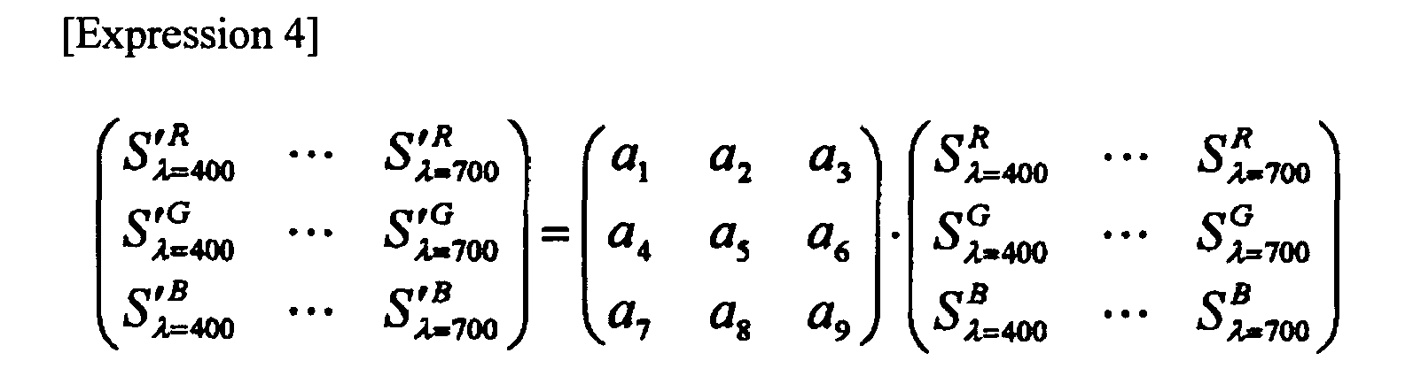
where S'R λ, S'G λ and S'B λ are corrected spectral characteristics of interest. - The corrected spectral characteristics of interest are transferred from the
function correcting section 300 to the conversioncoefficient calculating unit 108. - Spectral characteristics of interest obtained by using the nonlinear matrix coefficients as illustrated by Expression 3 can be converted as illustrated in Expression 5, for example.

- An exemplary configuration of the conversion
coefficient calculating unit 108 will be described below with reference toFig. 9 . - The conversion
coefficient calculating unit 108 includes a conversionfunction calculating section 400 which is conversion function calculating means and a spectralcharacteristic ROM 401 in which target spectral characteristics of the image pickup device which represent targeted color reproduction have been stored in advance. - The spectral
characteristic correcting unit 107 is connected to the conversionfunction calculating section 400. The spectralcharacteristic ROM 401 is also connected to the conversionfunction calculating section 400. The conversionfunction calculating section 400 is connected to theoutput unit 109. Thecontrol unit 110 is bidirectionally connected to the conversionfunction calculating section 400 and controls the conversionfunction calculating section 400. - Based on corrected spectral characteristics of interest S'R λ, S'G λ, and S'B λ, inputted from the spectral
characteristic correcting unit 107 and target spectral characteristics TR λ, TG λ and TB λ, which represent targeted color reproduction, read from the spectralcharacteristic ROM 401, the conversionfunction calculating section 400 calculates conversion matrix coefficients c1 to c9 used for conversion for approximating the corrected spectral characteristics to the target spectral characteristics by the method of least squares as illustrated by Expression 6:
- The conversion matrix coefficients c1 to c9 calculated by the conversion
function calculating section 400 are transferred to theoutput unit 109. - While the conversion matrix coefficients calculated by Expression 6 are linear 3 × 3 matrix coefficients, nonlinear matrix coefficients that include high-order terms (nonlinear terms) of multiplication off S'R λ, S'G λ, S'B λ. As with the calculation of linear matrix coefficients, nonlinear matrix coefficients can be calculated by the method of least squares. Specifically, nonlinear matrix coefficients can be calculated for example as illustrated by Expression 7:

where d11 to d36 represent coefficients of a nonlinear 3 × 6 matrix. In this way, d11 to d36 that provide the minimum solutions of the three expressions given in Expression 3 can be calculated. - While a CCD has been taken as an example of the image pickup device, the image pickup device may be a CMOS image pickup device or other type of image pickup device, of course.
- While a single-CCD image pickup device equipped with a Bayer primary color filter is used in the foregoing, it is not limited thereto. A single-CCD image pickup device equipped with a complementary color filter may be used. Any image pickup device equipped with a color filter having any multiple independent color components, whether a primary or complementary color filter, may be used.
- In addition, the image pickup device is not limited to a single-CCD. The image pickup device may be a two-CCD, three-CCD, or any other multi-CCD image pickup device.
- While the
transmissive color chart 120 is used in the foregoing, thecolor chart 120 is not limited thereto. For example, a reflective color chart can be used. In that case, a different external lighting apparatus, instead of light-box light source, is used to apply illuminating light to the color chart. - A circular rotary filter 130 (the filters have spectral characteristics as represented by O1 to O11 in
Fig. 11 ) may be provided in front of thelens system 100. Therotary filter 130 can be rotated to obtain a video signal of each color patch. - In addition, a light-emitting color chart which emits light in any narrow wavelength band may be used.
- While it is assumed that the processing described above is performed by hardware, the present invention is not limited to such a configuration. For example, an unprocessed video signal from the
CCD 101 may be inputted into a computer as raw data and a spectral characteristic correction program, which is separate software, may be executed by the computer to accomplish the processing. - Referring to
Fig. 11 , a flow of process by the spectral characteristic correction program will be described. - When the process is started, first an unprocessed video signal, spectral characteristics of interest of an image pickup device which are to be corrected, target spectral characteristics of the image pickup device which represent targeted color representation, spectral characteristics of a light source, and spectral characteristics of a color chart are inputted (step S1).
- Then, interpolation processing is applied to a video signal obtained at step S1 to generate a three video signal including all of color component signals for each pixel (step S2).
- Then, an average RGB signal of each color patch of the
color chart 120 is calculated from the video signal obtained at step S2 (step S3). The average RGB signal calculated here is called basic RGB signal. - Based on the target spectral characteristics of image pickup device that represent targeted color reproduction, the spectral characteristics of the light source, and the spectral characteristics of the color chart, a reference RGB signal is calculated as illustrated by Expression 1, for example (step S4).
- The luminance of the basic RGB signal is corrected so as to match the luminance of the reference RGB signal (step S5).
- Then, based on the basic RGB signal obtained at step S5 and the reference RGB signal, correction coefficients are calculated as illustrated by Expression 2 (or Expression 3), for example (step S6).
- Then, based on the correction coefficients obtained at step S6, the spectral characteristics of interest are corrected as illustrated by Expression 4 (or Expression 5) (step S7).
- Based on the corrected spectral characteristics of interest and the target spectral characteristics, conversion coefficients are calculated as illustrated by Expression 6 (or Expression 7) (step S8), then the process will end.
- While the spectral characteristic correction apparatus and the spectral characteristic correction program have been described, a spectral characteristic method that performs the same processing described above may be used.
- According to the first embodiment described above, spectral characteristics can be readily corrected since a video signal obtained by photographing a color chart is used to first correct spectral characteristics, then conversion coefficients are calculated on the basis of the corrected spectral characteristics and target spectral characteristics that represent targeted color reproduction.
- Furthermore, by correcting the spectral characteristics, a difference in color reproduction between two image pickup devices having different spectral characteristics can be minimized.
- Moreover, the calculated conversion coefficients can be used as coefficients for color conversion processing of image pickup apparatuses such as digital cameras and video cameras to achieve highly precise color conversion.
- The present invention is not limited to the embodiments described above. The present invention can be embodied by modifying any of components thereof in a practical phase without departing from the spirit of the present invention. By combining components disclosed in the above-described embodiments as appropriate, various implementations of the invention can be made. For example, some of the components given in the embodiments may be omitted. Furthermore, components in different embodiments may be combined as appropriate. It will be understood that various modifications and applications are possible without departing from the spirit of the present invention.
- This application is based upon and claims the benefit of priority from the prior Japanese Patent Application No.
2007-272951, filed on October 19, 2007
Claims (13)
- A spectral characteristic correction apparatus correcting a spectral characteristic characterizing a color signal including a plurality of chrominance signals, comprising:correction coefficient calculating means for calculating, on the basis of basic color signals corresponding to a plurality of basic colors and predetermined reference color signals corresponding to the basic color signals, a correction coefficient for performing correction for approximating the basic color signals to the reference color signals; andspectral characteristic correcting means for correcting a spectral characteristic characterizing the basic color signals by using the correction coefficient calculated by the correction coefficient calculating means.
- The spectral characteristic correction apparatus according to claim 1, further comprising:image pickup means for picking up an image of color patches of a plurality of colors to obtain a color signal; andsignal calculating means for calculating a color signal of each of the color patches as the basic color signal from the color signal obtained by the image pickup means.
- The spectral characteristic correction apparatus according to claim 1, further comprising conversion coefficient calculating means for calculating, on the basis of the spectral characteristic corrected by the spectral characteristic correcting means and the spectral characteristic characterizing the reference color signal, a conversion coefficient for performing conversion for approximating the corrected spectral characteristic to the spectral characteristic characterizing the reference color signal.
- The spectral characteristic correction apparatus according to claim 2, wherein the correction coefficient calculating means comprises correction function calculating means for calculating, on the basis of each of the chrominance signals of the basic color signal and each of the chrominance signals of the reference color signal, a coefficient of a correction function for performing correction for approximating each of the chrominance signals of the basic color signal to each of the chrominance signals of the reference color signal.
- The spectral characteristic correction apparatus according to claim 4, wherein the spectral characteristic correcting means comprises function correcting means for correcting the spectral characteristic characterizing the basic color signal by using the correction function.
- The spectral characteristic correction apparatus according to claim 3, wherein the conversion coefficient calculating means comprises conversion function calculating means for calculating, on the basis of the spectral characteristic corrected by the spectral characteristic correcting means and the spectral characteristic characterizing the reference color signal, a coefficient of a conversion function for performing conversion for approximating the corrected spectral characteristic to the spectral characteristic characterizing the reference color signal.
- The spectral characteristic correction apparatus according to claim 2, wherein the color patches transmit, reflect or emit light in a particular narrow wavelength band.
- A spectral characteristic correction method for correcting a spectral characteristic characterizing a color signal including a plurality of chrominance signals, comprising:a correction coefficient calculating step of calculating, on the basis of basic color signals corresponding to a plurality of basic colors and predetermined reference color signals corresponding to the basic color signals, a correction coefficient for performing correction for approximating the basic color signals to the reference color signals; anda spectral characteristic correcting step of correcting a spectral characteristic characterizing the basic color signals by using the correction coefficient calculated by the correction coefficient calculating step.
- The spectral characteristic correction method according to claim 8, further comprising:an image pickup step of picking up an image of color patches of a plurality of colors to obtain a color signal; anda signal calculating step of calculating a color signal of each of the color patches as the basic color signal from the color signal obtained by the image pickup step.
- The spectral characteristic correction method according to claim 8, further comprising a conversion coefficient calculating step of calculating, on the basis of the spectral characteristic corrected by the spectral characteristic correcting step and the spectral characteristic characterizing the reference color signal, a conversion coefficient for performing conversion for approximating the corrected spectral characteristic to the spectral characteristic characterizing the reference color signal.
- The spectral characteristic correction method according to claim 9, wherein the correction coefficient calculating step comprises a correction function calculating step of calculating, on the basis of each of the chrominance signals of the basic color signal and each of the chrominance signals of the reference color signal, a coefficient of a correction function for performing correction for approximating each of the chrominance signals of the basic color signal to each of the chrominance signals of the reference color signal.
- The spectral characteristic correction method according to claim 11, wherein the spectral characteristic correcting step comprises function correcting step of correcting the spectral characteristic characterizing the basic color signal by using the correction function.
- The spectral characteristic correction method according to claim 10, wherein the conversion coefficient calculating step comprises a conversion function calculating step of calculating, on the basis of the spectral characteristic corrected by the spectral characteristic correcting step and the spectral characteristic characterizing the reference color signal, a coefficient of a conversion function for performing conversion for approximating the corrected spectral characteristic to the spectral characteristic characterizing the reference color signal.
Applications Claiming Priority (2)
| Application Number | Priority Date | Filing Date | Title |
|---|---|---|---|
| JP2007272951A JP5052286B2 (en) | 2007-10-19 | 2007-10-19 | Spectral characteristic correction apparatus, spectral characteristic correction method |
| PCT/JP2008/066673 WO2009050973A1 (en) | 2007-10-19 | 2008-09-16 | Spectral characteristic correction device and spectral characteristic correction method |
Publications (2)
| Publication Number | Publication Date |
|---|---|
| EP2205002A1 true EP2205002A1 (en) | 2010-07-07 |
| EP2205002A4 EP2205002A4 (en) | 2013-01-02 |
Family
ID=40567249
Family Applications (1)
| Application Number | Title | Priority Date | Filing Date |
|---|---|---|---|
| EP08838577A Withdrawn EP2205002A4 (en) | 2007-10-19 | 2008-09-16 | Spectral characteristic correction device and spectral characteristic correction method |
Country Status (5)
| Country | Link |
|---|---|
| US (1) | US8493463B2 (en) |
| EP (1) | EP2205002A4 (en) |
| JP (1) | JP5052286B2 (en) |
| CN (1) | CN101828404B (en) |
| WO (1) | WO2009050973A1 (en) |
Cited By (2)
| Publication number | Priority date | Publication date | Assignee | Title |
|---|---|---|---|---|
| EP2166771A4 (en) * | 2007-05-31 | 2010-11-17 | Olympus Corp | Signal processing device and signal processing program |
| EP3200362A4 (en) * | 2014-09-22 | 2017-10-04 | Fujitsu Ltd. | Reproduction apparatus, reproduction method, program, and system |
Families Citing this family (5)
| Publication number | Priority date | Publication date | Assignee | Title |
|---|---|---|---|---|
| JP5090146B2 (en) * | 2007-12-06 | 2012-12-05 | オリンパス株式会社 | Color conversion coefficient calculation device, color conversion coefficient calculation program, and color conversion coefficient calculation method |
| CN103747243A (en) * | 2013-12-31 | 2014-04-23 | 深圳市华星光电技术有限公司 | LCD (Liquid Crystal Display) full-grayscale data acquisition method on basis of CCD (Charge Coupled Device) camera |
| JP6427926B2 (en) * | 2014-04-11 | 2018-11-28 | 株式会社シグマ | Color reproduction correction method, color reproduction correction apparatus, and imaging apparatus |
| WO2023032256A1 (en) * | 2021-09-03 | 2023-03-09 | ソニーセミコンダクタソリューションズ株式会社 | Spectral sensitivity measurement device and spectral sensitivity measurement method |
| KR102778437B1 (en) * | 2022-12-28 | 2025-03-11 | (주) 픽셀플러스 | Method and device for color reproduction of image |
Family Cites Families (13)
| Publication number | Priority date | Publication date | Assignee | Title |
|---|---|---|---|---|
| JP2001358960A (en) | 2000-04-14 | 2001-12-26 | Fuji Photo Film Co Ltd | Color conversion coefficient introducing method, color conversion method, recording medium and color converter |
| JP2003134536A (en) * | 2001-10-19 | 2003-05-09 | Minolta Co Ltd | Color correction system, color correction data generating system, and program |
| US7586642B2 (en) * | 2003-07-25 | 2009-09-08 | Hoya Corporation | Color-space transformation-matrix calculating system and calculating method |
| JP2005079834A (en) * | 2003-08-29 | 2005-03-24 | Pentax Corp | Color conversion matrix calculation method and image signal processing apparatus |
| JP2005117524A (en) | 2003-10-10 | 2005-04-28 | Canon Inc | Image processing system |
| JP3966866B2 (en) * | 2004-04-13 | 2007-08-29 | 三菱電機株式会社 | Imaging apparatus, camera, and signal processing method |
| JP4468734B2 (en) * | 2004-04-27 | 2010-05-26 | オリンパス株式会社 | Video signal processing apparatus and video signal processing program |
| FI20040834A0 (en) * | 2004-06-17 | 2004-06-17 | Petri Piirainen | Method for color calibrating camera and / or display device |
| US7545421B2 (en) * | 2004-10-28 | 2009-06-09 | Qualcomm Incorporated | Apparatus, system, and method for optimizing gamma curves for digital image devices |
| JP4501634B2 (en) * | 2004-10-29 | 2010-07-14 | 富士フイルム株式会社 | Matrix coefficient determination method and image input apparatus |
| JP4540492B2 (en) * | 2005-01-28 | 2010-09-08 | Hoya株式会社 | Color conversion matrix calculation method and image signal processing apparatus |
| JP4290136B2 (en) * | 2005-03-14 | 2009-07-01 | キヤノン株式会社 | Color processing apparatus and method |
| JP4526445B2 (en) * | 2005-06-15 | 2010-08-18 | オリンパス株式会社 | Imaging device |
-
2007
- 2007-10-19 JP JP2007272951A patent/JP5052286B2/en not_active Expired - Fee Related
-
2008
- 2008-09-16 EP EP08838577A patent/EP2205002A4/en not_active Withdrawn
- 2008-09-16 WO PCT/JP2008/066673 patent/WO2009050973A1/en not_active Ceased
- 2008-09-16 CN CN2008801121805A patent/CN101828404B/en not_active Expired - Fee Related
-
2010
- 2010-04-15 US US12/760,624 patent/US8493463B2/en not_active Expired - Fee Related
Cited By (4)
| Publication number | Priority date | Publication date | Assignee | Title |
|---|---|---|---|---|
| EP2166771A4 (en) * | 2007-05-31 | 2010-11-17 | Olympus Corp | Signal processing device and signal processing program |
| US8330833B2 (en) | 2007-05-31 | 2012-12-11 | Olympus Corporation | Signal processing apparatus for determining color conversion processing for color-converting second color signal obtained by second image pickup device to color signal approximate to first color signal obtained by target first image pickup device and non-transitory computer-readable recording medium for recording signal processing program for the color conversion processing |
| EP3200362A4 (en) * | 2014-09-22 | 2017-10-04 | Fujitsu Ltd. | Reproduction apparatus, reproduction method, program, and system |
| US10075239B2 (en) | 2014-09-22 | 2018-09-11 | Fujitsu Limited | Reproduction device, method, storage medium, and system |
Also Published As
| Publication number | Publication date |
|---|---|
| CN101828404B (en) | 2012-07-18 |
| EP2205002A4 (en) | 2013-01-02 |
| CN101828404A (en) | 2010-09-08 |
| US20100201839A1 (en) | 2010-08-12 |
| JP2009105495A (en) | 2009-05-14 |
| US8493463B2 (en) | 2013-07-23 |
| WO2009050973A1 (en) | 2009-04-23 |
| JP5052286B2 (en) | 2012-10-17 |
Similar Documents
| Publication | Publication Date | Title |
|---|---|---|
| JP3624604B2 (en) | Color reproduction correction apparatus and correction method for imaging apparatus | |
| US8493463B2 (en) | Spectral characteristic correction apparatus, spectral characteristic correction method and recording medium on which spectral characteristic correction program is recorded | |
| CN100559886C (en) | Electronic imaging device and electronic imaging method | |
| EP1450302A1 (en) | Color reproduction system | |
| JP3663941B2 (en) | Spectral sensitivity characteristic measuring method and imaging data construction method of imaging apparatus | |
| CN102204258A (en) | image input device | |
| US20060170942A1 (en) | Color-space transformation-matrix calculating method and image processing device | |
| CN101540919A (en) | Imaging apparatus | |
| US8174585B2 (en) | Color conversion coefficient calculation apparatus, computer readable recording medium for recording color conversion coefficient calculation program, and color conversion coefficient calculation method | |
| US20180040107A1 (en) | Image processing device, imaging device, image processing method, and program | |
| US10326947B2 (en) | Image processing device, imaging device, image processing method, and program | |
| CN115665565A (en) | Online tobacco leaf image color correction method, system and device | |
| EP2717155A1 (en) | Color distortion correction method and device for imaging systems and image output systems | |
| US7852380B2 (en) | Signal processing system and method of operation for nonlinear signal processing | |
| JP4011039B2 (en) | Imaging apparatus and signal processing method | |
| US20080310710A1 (en) | Direct calibration of color imaging devices | |
| US8169475B2 (en) | Image processing system, imaging system, and microscope imaging system | |
| GB2460241A (en) | Correction of optical lateral chromatic aberration | |
| JP4874752B2 (en) | Digital camera | |
| JP5295022B2 (en) | Color correction apparatus and color correction method | |
| JP5033702B2 (en) | Imaging device | |
| EP3131291A1 (en) | System and method for acquiring color image from monochrome scan camera | |
| JP5288702B2 (en) | Color correction calculation method | |
| EP2204980B1 (en) | Image processing system, imaging system, and microscope imaging system | |
| JP4397724B2 (en) | Imaging apparatus, camera, and signal processing method |
Legal Events
| Date | Code | Title | Description |
|---|---|---|---|
| PUAI | Public reference made under article 153(3) epc to a published international application that has entered the european phase |
Free format text: ORIGINAL CODE: 0009012 |
|
| 17P | Request for examination filed |
Effective date: 20100419 |
|
| AK | Designated contracting states |
Kind code of ref document: A1 Designated state(s): AT BE BG CH CY CZ DE DK EE ES FI FR GB GR HR HU IE IS IT LI LT LU LV MC MT NL NO PL PT RO SE SI SK TR |
|
| AX | Request for extension of the european patent |
Extension state: AL BA MK RS |
|
| DAX | Request for extension of the european patent (deleted) | ||
| A4 | Supplementary search report drawn up and despatched |
Effective date: 20121205 |
|
| RIC1 | Information provided on ipc code assigned before grant |
Ipc: H04N 9/04 20060101AFI20121129BHEP |
|
| STAA | Information on the status of an ep patent application or granted ep patent |
Free format text: STATUS: THE APPLICATION HAS BEEN WITHDRAWN |
|
| 18W | Application withdrawn |
Effective date: 20130121 |