EP2204593A2 - Mit Gewinde versehene Rohrverbindung, die Biegungsbeanspruchungen widersteht - Google Patents
Mit Gewinde versehene Rohrverbindung, die Biegungsbeanspruchungen widersteht Download PDFInfo
- Publication number
- EP2204593A2 EP2204593A2 EP09010110A EP09010110A EP2204593A2 EP 2204593 A2 EP2204593 A2 EP 2204593A2 EP 09010110 A EP09010110 A EP 09010110A EP 09010110 A EP09010110 A EP 09010110A EP 2204593 A2 EP2204593 A2 EP 2204593A2
- Authority
- EP
- European Patent Office
- Prior art keywords
- threaded connection
- connection according
- threaded
- male
- profile
- Prior art date
- Legal status (The legal status is an assumption and is not a legal conclusion. Google has not performed a legal analysis and makes no representation as to the accuracy of the status listed.)
- Granted
Links
Images

Classifications
-
- F—MECHANICAL ENGINEERING; LIGHTING; HEATING; WEAPONS; BLASTING
- F16—ENGINEERING ELEMENTS AND UNITS; GENERAL MEASURES FOR PRODUCING AND MAINTAINING EFFECTIVE FUNCTIONING OF MACHINES OR INSTALLATIONS; THERMAL INSULATION IN GENERAL
- F16L—PIPES; JOINTS OR FITTINGS FOR PIPES; SUPPORTS FOR PIPES, CABLES OR PROTECTIVE TUBING; MEANS FOR THERMAL INSULATION IN GENERAL
- F16L15/00—Screw-threaded joints; Forms of screw-threads for such joints
- F16L15/001—Screw-threaded joints; Forms of screw-threads for such joints with conical threads
- F16L15/002—Screw-threaded joints; Forms of screw-threads for such joints with conical threads with more then one threaded section
Definitions
- the invention relates to a threaded tubular connection for a tubular string which is subjected to dynamic bending loads, comprising a male tubular element provided with a male threaded portion and a female tubular element provided with a female threaded portion.
- That type of threaded connection is intended for making strings for hydrocarbon or the like wells.
- strings connecting an offshore platform to the sea bed are subjected to variable (dynamic) bending loads. Said loads are transmitted from one tube to the next in the string through the threaded connections.
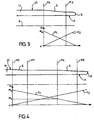
- Figure 3 shows that the last threads of the male element and the female element are subjected to a maximum bending moment which has to be transmitted in addition to the whole of the axial tensile load.
- Said dynamic loads also cause friction between the parts of the male and female elements in contact, leading to cracking due to fretting fatigue.
- the aim of the invention is to overcome these disadvantages thanks to an appropriate distribution of bending loads and optionally of tensile loads.
- the invention also aims to provide spaces to house lubricating grease and the debris resulting from wear of the surfaces in contact.
- a further aim is to provide sealing surfaces between the threaded portions and the outside of the threaded connection which do not constitute a source of cracking due to fretting fatigue.
- a final aim is to provide multiple sealing surfaces which enable to maintain a seal in the event of deterioration of certain thereof.
- the invention provides a threaded connection of the type defined in the introduction, comprising at least one transfer zone axially disposed between said threaded portions and the free end of one of said tubular elements, it being axially spaced from said threaded portions in order to transfer a fraction of at least 20%, preferably at least 30% of the bending moment to which the connection is subjected from one element to the other, the male and female elements having respective transfer surfaces in mutual contact with a radial interference fit in said transfer zone, at least one of the transfer surfaces being an undulated surface defining a series of annular rounded ribs which come into interfering contact with the facing transfer surface, the maximum diameter point and the minimum diameter point of the undulation profile being located on respective rounded portions of the profile.
- the invention also provides a process to improve the resistance to fatigue of a threaded tubular connection subjected to dynamic bending loads, said connection comprising a male tubular element with a male threaded portion and a female tubular element with a female threaded portion, characterized in that the connection comprises at least a transfer zone axially located between said threaded portions and the free end of one of said tubular elements while being axially spaced from said threaded portions so as to transfer from one element to the other element a fraction at least equal to 20 % of the bending moment undergone by the connection, the male and female elements having in said transfer zone respective transfer surfaces which are in mutual contact and interfere radially, one at least of the transfer surfaces comprising means suited for spacing radially the contact locations from the section where the stresses applied to the connection run, in particular in the form of a series of rounded annular ribs.
- the threaded tubular connection shown in Figure 1 comprises a male tubular element 1 and a female tubular element 2 provided with respective tapered threaded portions 3, 4 which cooperate for mutual makeup of the two elements.
- the element 1 is formed at one end of a great length tube 11 and element 2 is formed at one end of a tubular coupling 12 for connecting two tubes similar to 11.
- a plurality of tubes similar to 11 each one of which has two threaded elements similar to 1 at its ends can then be connected together through couplings similar to 12 each one of which has two threaded elements similar to 2 at its ends to form a string of tubes for an oil well, for example.
- tube 11 has between its two male elements i.e. over the major portion of its length, termed the regular portion, a uniform external diameter ED of 177.8 mm (7 inches) which represents the nominal diameter of the threaded connection.
- ED 177.8 mm (7 inches) which represents the nominal diameter of the threaded connection.
- the values for the dimensions given below take this nominal diameter into account and can vary therefrom.
- the threaded tubular connection has a transfer zone which is axially defined by transverse planes P1 and P2, in which the male and female elements are in mutual contact through respective annular transfer surfaces 5, 6 of revolution around the axis A of the threaded portions; they have well defined profiles.
- the profile of surface 5 is shown in Figure 2 .
- the profile is an undulated periodic profile defined by repetition of a motif formed by three mutually tangential circular arcs, namely a first arc A1 which is outwardly convex, i.e. the concavity of which is turned towards the axis A, passing through a point P M with a maximum profile diameter, a second concave arc A2 (the concavity of which is turned radially outwardly) passing through a point P m with a minimum profile diameter, and a third convex arc A3, the radii of said three arcs being respectively 0.8, 1.6 and 8 mm in the example shown.
- the profile of surface 5 is also asymmetric, the axial distance d 1 between a point P M with a maximum profile diameter and the following minimum diameter point P m , starting from the free end 7 of the male element, i.e. from the right in Figure 2 , being less than the axial distance d 2 between the point P m and the following maximum diameter point P' M of the profile.
- the distances d 1 and d 2 in this case are about 1 mm and 2 mm respectively.
- the profile of surface 5 is generally inclined with respect to axis A, the straight lines L3 and L4 being respectively tangential to the set of arcs A1 and to the set of arcs A2, and thus constituting the outer and inner envelopes of said profile, being inclined at 2° with respect to said axis, growing closer thereto in the direction of the free end of the male element. Because of said inclination, the terms "maximum diameter point” and “minimum diameter point” refer to maximum and minimum diameters which are relative rather than absolute.
- the amplitude of the undulations in surface 5, i.e. the radial distance e between lines L3 and L4, is 0.2 mm.
- the surface 6 of the female element facing surface 5, not shown in detail, is a tapered smooth surface the slope of which is equal to that of lines L3 and L4, so that the peaks of the different annular ribs 7 defined by surface 5 come into simultaneous contact with surface 6 when screwing the male threaded portion 3 into the female threaded portion 4.
- the dimensions of surfaces 5 and 6 are such that radial interference occurs at the end of screwing between the peaks of the ribs and the surface 6, said radial interference fit, i.e. the difference in diameter between the male and female elements measured prior to coupling at points which will come into interfering contact after makeup, being uniform from one rib to the other and advantageously being 0.4 mm.
- the contact surfaces between the crests of the ribs 7 and the surface 5 are radially spaced from the section defined between the cone the generatrix of which is L4 (internal envelope of the ribs) and the opposed peripheral surface (internal) of the male element 1 where the stresses applied to the connection are fully exerted (i.e. where they run), improving thus the resistance to fatigue of said connection when it is subjected to dynamic bending loads.
- Too small an axial distance d 1 + d 2 (corresponding to the pitch of the ribs), for example smaller than 0.5 mm does not easily enable to form a sufficient undulation amplitude for the rounded portions under consideration. For that reason it is preferable to have an axial distance d 1 + d 2 over 1 mm. Nevertheless too large an axial distance d 1 + d 2 does not allow to house several ribs in the transfer zone unless said transfer zone is extended in an excessive way which is not cheaply produced.
- An inclination above 5° is not desirable because it reduces too much the critical section of the male element 1 (minimum section of the element on which the whole of the axial loads are exerted on the connection) with respect to the section of the regular portion of the tube 11 and in consequence the efficiency of the connection.
- Too low an undulation amplitude for example lower than 0.5 mm does not allow to distance the section contacts where the axial stresses are exerted neither does it allow to store the wear debris as will be seen further on.
- Too big an undulation amplitude reduces the critical section with the drawbacks mentioned above.
- each rib 7 defines an annular sealing contact surface with the surface 6, the multiplicity of said sealing surfaces reducing the risk of loss of a seal between the threaded portion zone 3, 4 and the outside of the threaded connection.
- This seal can be produced by direct contact of the constituent metallic materials of the male and female elements.
- a sealing material such as an elastomer or a softer metal than that of the male and female elements (for example copper on steel) may be interposed between the substrate materials in the form of a coating or of an added ring.
- a further possibility consists of subjecting one and/or other of the contact surfaces to a surface treatment which encourages a seal.
- Too small a radial interference between the crests of the ribs and surface 6 does not allow a seal between surfaces 5 and 6. Too large a radial interference risks inducing galling between surfaces 5 and 6 during make up, which galling is detrimental to the behavior to fatigue of the connection and to the seal between surfaces 5 and 6.
- a roughness Ra > 3.2 micrometers is not desirable. For instance one can choose a roughness Ra ⁇ 1.6 micrometers.
- male threaded portion 3 extends from a transverse plane P3 close to the free end 8 of the male element 1 to a transverse plane P4 which is directly followed by the regular portion 21 of the tube 11 to which the male element 1 belongs.
- a bending load is applied to the tubular connection of which element 1 forms a part, this latter experiences a bending moment which varies along the axis A, following the curve C1, shown as a straight line.
- This moment M has a maximum value M 0 in the plane P4.
- the bending moment experienced by the female element not shown, varies as the curve C2, shown as a straight line, that moment being zero in the plane P4 and increasing progressively in the direction of the free end 8.
- the bending moment M experienced by the male element 1 takes a maximum value M 0 in the plane P2 which separates the transfer surface 5 and the regular portion 21 of the tube 11.
- the bending moment experienced by the threaded portion 3 has a maximum value M 1 in the plane P4 which defines the threaded portion 3 opposite the free end 8 of the male element.
- the maximum diameter of the transfer surface 5 is equal to the diameter of the regular portion 21 of the tube 11.
- M max YS • I zz OD / 2
- F the product of an area S of the transfer zone and the maximum pressure stress to be applied to this zone, which equals the yield strength YS multiplied by a fraction f' which must not be exceeded.
- this distance represents substantially 150% of the axial length of the female threaded portion, which is 51 mm, the axial length of the transfer zone being 13.2 mm.
- the invention also encompasses reducing the thickness of said element, in the region facing the contact surfaces 5 and 6, to increase its flexibility.
- a depression 13 is formed on the outer peripheral surface 14 of the coupling, said depression having the profile of a large radius concave circular arc (more than 50 mm), in this case equal to 150 mm.
- This depression defines a minimum external diameter Dm facing a median point P of the transfer zone 5, 6, the external diameter increasing progressively either side of said point.
- the depression 13 connects to the cylindrical portion, with a maximum diameter, of the external surface 14.
- the depression 13 connects to a chamfer 16 adjacent to the end 15.
- the minimum diameter of said chamfer i.e. the diameter of element 2 at the junction between the chamfer 16 and the end face 15, is substantially equal to the diameter Dm of the bottom of the depression.
- the diameter Dm is also selected so as not to have the bending inertia of the female element in the corresponding plane less than the product of the bending inertia I ZZ of the regular portion of the tube 11 and the fraction f of the bending moment to be transferred.
- transfer zone of the invention has been described in combination with a depression on the outer surface of a coupling, the transfer zone can be produced independently of the depression, in particular in the case of a connection which is termed an integral connection in which the male and female elements both form part of great length tubes.
Landscapes
- Engineering & Computer Science (AREA)
- General Engineering & Computer Science (AREA)
- Mechanical Engineering (AREA)
- Non-Disconnectible Joints And Screw-Threaded Joints (AREA)
- Joints With Pressure Members (AREA)
- Mutual Connection Of Rods And Tubes (AREA)
- Quick-Acting Or Multi-Walled Pipe Joints (AREA)
Priority Applications (1)
| Application Number | Priority Date | Filing Date | Title |
|---|---|---|---|
| PL09010110T PL2204593T3 (pl) | 2004-03-26 | 2005-03-22 | Gwintowe złącze rurowe, które jest odporne na naprężenia zginające |
Applications Claiming Priority (2)
| Application Number | Priority Date | Filing Date | Title |
|---|---|---|---|
| FR0403147A FR2868146B1 (fr) | 2004-03-26 | 2004-03-26 | Joint filete tubulaire resistant aux contraintes de flexion |
| EP05716320A EP1728018B9 (de) | 2004-03-26 | 2005-03-22 | Gegen biegespannungen resistente gewinderohrverbindung |
Related Parent Applications (4)
| Application Number | Title | Priority Date | Filing Date |
|---|---|---|---|
| WOPCT/EP2005/003086 Previously-Filed-Application | 2005-03-22 | ||
| EP05716320.6 Division | 2005-03-22 | ||
| EP05716320A Division EP1728018B9 (de) | 2004-03-26 | 2005-03-22 | Gegen biegespannungen resistente gewinderohrverbindung |
| PCT/EP2005/003086 Previously-Filed-Application WO2005093309A1 (en) | 2003-05-30 | 2005-03-22 | Threaded tubular connection which is resistant to bending stresses |
Publications (4)
| Publication Number | Publication Date |
|---|---|
| EP2204593A2 true EP2204593A2 (de) | 2010-07-07 |
| EP2204593A3 EP2204593A3 (de) | 2010-07-28 |
| EP2204593B1 EP2204593B1 (de) | 2013-12-04 |
| EP2204593B8 EP2204593B8 (de) | 2014-01-08 |
Family
ID=34945831
Family Applications (2)
| Application Number | Title | Priority Date | Filing Date |
|---|---|---|---|
| EP09010110.6A Not-in-force EP2204593B8 (de) | 2004-03-26 | 2005-03-22 | Mit Gewinde versehene Rohrverbindung, die Biegungsbeanspruchungen widersteht |
| EP05716320A Active EP1728018B9 (de) | 2004-03-26 | 2005-03-22 | Gegen biegespannungen resistente gewinderohrverbindung |
Family Applications After (1)
| Application Number | Title | Priority Date | Filing Date |
|---|---|---|---|
| EP05716320A Active EP1728018B9 (de) | 2004-03-26 | 2005-03-22 | Gegen biegespannungen resistente gewinderohrverbindung |
Country Status (13)
| Country | Link |
|---|---|
| US (1) | US7661727B2 (de) |
| EP (2) | EP2204593B8 (de) |
| JP (1) | JP4964759B2 (de) |
| CN (1) | CN100516613C (de) |
| AR (1) | AR048188A1 (de) |
| AT (1) | ATE443226T1 (de) |
| BR (1) | BRPI0509259B1 (de) |
| CA (1) | CA2558761C (de) |
| DE (1) | DE602005016657D1 (de) |
| FR (1) | FR2868146B1 (de) |
| PL (2) | PL1728018T3 (de) |
| RU (1) | RU2352848C2 (de) |
| WO (1) | WO2005093309A1 (de) |
Cited By (1)
| Publication number | Priority date | Publication date | Assignee | Title |
|---|---|---|---|---|
| EP3712483A4 (de) * | 2017-11-14 | 2021-03-03 | Joint Stock Company "Pervouralsk Pipe Plant" (JSC "Pintz") | Schraubverbindung für ölfeldrohre |
Families Citing this family (16)
| Publication number | Priority date | Publication date | Assignee | Title |
|---|---|---|---|---|
| FR2844331B1 (fr) * | 2002-01-03 | 2004-11-26 | Vallourec Mannesmann Oil & Gas | Procede de realisation d'un joint tubulaire etanche avec expansion plastique |
| FR2863681B1 (fr) * | 2003-12-11 | 2006-02-24 | Vallourec Mannesmann Oil & Gas | Joint tubulaire a filetages coniques resistant a la fatigue |
| US7798536B2 (en) * | 2005-08-11 | 2010-09-21 | Weatherford/Lamb, Inc. | Reverse sliding seal for expandable tubular connections |
| DE102007041528A1 (de) | 2007-08-31 | 2009-03-05 | Robert Bosch Gmbh | Zündeinrichtung für eine Laserzündung einer Brennkraftmaschine |
| FR2925946B1 (fr) * | 2007-12-28 | 2009-12-11 | Vallourec Mannesmann Oil & Gas | Joint filete tubulaire etanche et resistant a des sollicitations successives de pressions |
| FR2937077B1 (fr) | 2008-10-15 | 2010-10-22 | Vallourec Mannesmann Oil & Gas | Composant pour le forage et l'exploitation des puits d'hydrocarbures |
| FR2940677B1 (fr) * | 2008-12-29 | 2016-07-22 | Vallourec Mannesmann Oil & Gas France | Joint tubulaire etanche utilise dans l'industrie du petrole |
| FR2961576B1 (fr) | 2010-06-17 | 2012-08-03 | Vallourec Mannesmann Oil & Gas | Joint filete et procede de realisation |
| US8960302B2 (en) | 2010-10-12 | 2015-02-24 | Bp Corporation North America, Inc. | Marine subsea free-standing riser systems and methods |
| EP2627859A2 (de) | 2010-10-12 | 2013-08-21 | BP Corporation North America Inc. | Marine unterwasseranordnungen |
| EP3660377A1 (de) | 2010-12-01 | 2020-06-03 | Vermeer Manufacturing Company | Konischer gewindegang mit verbesserter beständigkeit |
| SE535814C2 (sv) | 2011-05-20 | 2013-01-02 | Atlas Copco Secoroc Ab | Gänganordning, gängförband samt borrsträngskomponent för slående bergborrning |
| CN102829269B (zh) * | 2012-08-30 | 2014-06-04 | 中国石油天然气集团公司 | 地下储气库注气和采气用特殊螺纹接头 |
| EP2845993B1 (de) * | 2013-09-09 | 2018-01-10 | Sandvik Intellectual Property AB | Energieübertragungseffiziente Schlagbohrstrangkupplung |
| WO2015153271A1 (en) * | 2014-04-04 | 2015-10-08 | Enventure Global Technology, Llc | Expandable metal-to-metal seal connection |
| CN110500044B (zh) * | 2019-09-27 | 2024-02-09 | 衡阳华菱钢管有限公司 | 抗疲劳套管的螺纹接头 |
Citations (2)
| Publication number | Priority date | Publication date | Assignee | Title |
|---|---|---|---|---|
| WO2001075346A1 (fr) | 2000-03-31 | 2001-10-11 | Vallourec Mannesmann Oil & Gas France | Element filete tubulaire pour joint filete tubulaire resistant a la fatigue et joint filete tubulaire resultant |
| WO2001075345A1 (fr) | 2000-03-31 | 2001-10-11 | Vallourec Mannesmann Oil & Gas France | Element filete tubulaire delarde resistant a la fatigue |
Family Cites Families (23)
| Publication number | Priority date | Publication date | Assignee | Title |
|---|---|---|---|---|
| US1942518A (en) * | 1933-06-22 | 1934-01-09 | Pittsburgh Steel Co | Pipe joint |
| US2308066A (en) * | 1940-11-15 | 1943-01-12 | Hughes Tool Co | Tool joint assembly |
| US2992613A (en) * | 1960-08-30 | 1961-07-18 | Albert G Bodine | Sonic well pump tubing string |
| BE633562A (de) * | 1962-06-26 | |||
| US4384737A (en) * | 1980-04-25 | 1983-05-24 | Republic Steel Corporation | Threaded joint for well casing and tubing |
| GB8617827D0 (en) * | 1986-07-22 | 1986-08-28 | British Steel Corp | Joints for tubular members |
| US4946201A (en) * | 1989-03-08 | 1990-08-07 | Baroid Technology, Inc. | Oil field tubular connection |
| CN2046578U (zh) * | 1989-04-19 | 1989-10-25 | 陈贵生 | 泵管螺纹连接锁紧器 |
| US4915426A (en) * | 1989-06-01 | 1990-04-10 | Skipper Claud T | Pipe coupling for well casing |
| JPH0763289A (ja) * | 1993-08-26 | 1995-03-07 | Nippon Steel Corp | 曲げ強度の優れた油井管継手 |
| IT1272733B (it) * | 1993-10-19 | 1997-06-26 | Agip Spa | Giunzione integrale perfezionata di due tubazioni |
| GB9706084D0 (en) * | 1997-03-24 | 1997-05-14 | Oil States Ind Uk Ltd | Improvements in and relating to pipe connectors |
| US6056324A (en) * | 1998-05-12 | 2000-05-02 | Dril-Quip, Inc. | Threaded connector |
| US6305723B1 (en) * | 1998-10-27 | 2001-10-23 | Grant Prideco, L.P. | Tool joint and drill pipe made therefrom |
| US6254146B1 (en) * | 1999-04-23 | 2001-07-03 | John Gandy Corporation | Thread form with multifacited flanks |
| FR2800150B1 (fr) * | 1999-10-21 | 2001-12-07 | Vallourec Mannesmann Oil & Gas | Joint tubulaire filette etanche a la pression exterieure |
| DE19955377C2 (de) | 1999-11-10 | 2002-05-02 | Mannesmann Ag | Rohrverbindung |
| US6494499B1 (en) * | 2000-10-31 | 2002-12-17 | The Technologies Alliance, Inc. | Threaded connector for pipe |
| JP4069659B2 (ja) * | 2001-05-24 | 2008-04-02 | 住友金属工業株式会社 | 耐焼付き性に優れた鋼管用ねじ継手 |
| JP3876656B2 (ja) * | 2001-07-13 | 2007-02-07 | 住友金属工業株式会社 | 管用ねじ継手 |
| FR2833335B1 (fr) * | 2001-12-07 | 2007-05-18 | Vallourec Mannesmann Oil & Gas | Joint filete tubulaire superieur contenant au moins un element filete avec levre d'extremite |
| ITRM20020512A1 (it) * | 2002-10-10 | 2004-04-11 | Tenaris Connections Bv | Tubo filettato con trattamento superficiale. |
| ITRM20050069A1 (it) * | 2005-02-17 | 2006-08-18 | Tenaris Connections Ag | Giunzione filettata per tubi provvista di tenuta. |
-
2004
- 2004-03-26 FR FR0403147A patent/FR2868146B1/fr not_active Expired - Fee Related
-
2005
- 2005-03-22 PL PL05716320T patent/PL1728018T3/pl unknown
- 2005-03-22 WO PCT/EP2005/003086 patent/WO2005093309A1/en active Application Filing
- 2005-03-22 BR BRPI0509259-0A patent/BRPI0509259B1/pt active IP Right Grant
- 2005-03-22 US US10/594,112 patent/US7661727B2/en active Active
- 2005-03-22 JP JP2007504350A patent/JP4964759B2/ja active Active
- 2005-03-22 DE DE602005016657T patent/DE602005016657D1/de active Active
- 2005-03-22 CN CNB2005800098013A patent/CN100516613C/zh active Active
- 2005-03-22 EP EP09010110.6A patent/EP2204593B8/de not_active Not-in-force
- 2005-03-22 CA CA2558761A patent/CA2558761C/en active Active
- 2005-03-22 AT AT05716320T patent/ATE443226T1/de active
- 2005-03-22 RU RU2006137698/06A patent/RU2352848C2/ru active
- 2005-03-22 PL PL09010110T patent/PL2204593T3/pl unknown
- 2005-03-22 EP EP05716320A patent/EP1728018B9/de active Active
- 2005-03-23 AR ARP050101151A patent/AR048188A1/es active IP Right Grant
Patent Citations (2)
| Publication number | Priority date | Publication date | Assignee | Title |
|---|---|---|---|---|
| WO2001075346A1 (fr) | 2000-03-31 | 2001-10-11 | Vallourec Mannesmann Oil & Gas France | Element filete tubulaire pour joint filete tubulaire resistant a la fatigue et joint filete tubulaire resultant |
| WO2001075345A1 (fr) | 2000-03-31 | 2001-10-11 | Vallourec Mannesmann Oil & Gas France | Element filete tubulaire delarde resistant a la fatigue |
Cited By (1)
| Publication number | Priority date | Publication date | Assignee | Title |
|---|---|---|---|---|
| EP3712483A4 (de) * | 2017-11-14 | 2021-03-03 | Joint Stock Company "Pervouralsk Pipe Plant" (JSC "Pintz") | Schraubverbindung für ölfeldrohre |
Also Published As
| Publication number | Publication date |
|---|---|
| DE602005016657D1 (de) | 2009-10-29 |
| EP2204593A3 (de) | 2010-07-28 |
| EP1728018A1 (de) | 2006-12-06 |
| WO2005093309A1 (en) | 2005-10-06 |
| EP1728018B1 (de) | 2009-09-16 |
| EP2204593B1 (de) | 2013-12-04 |
| ATE443226T1 (de) | 2009-10-15 |
| JP4964759B2 (ja) | 2012-07-04 |
| CA2558761C (en) | 2012-03-13 |
| EP1728018B9 (de) | 2012-04-25 |
| CN100516613C (zh) | 2009-07-22 |
| CA2558761A1 (en) | 2005-10-06 |
| BRPI0509259A (pt) | 2007-09-11 |
| FR2868146B1 (fr) | 2009-01-23 |
| RU2006137698A (ru) | 2008-05-10 |
| EP2204593B8 (de) | 2014-01-08 |
| AR048188A1 (es) | 2006-04-05 |
| CN1938541A (zh) | 2007-03-28 |
| BRPI0509259B1 (pt) | 2018-06-12 |
| US20070187951A1 (en) | 2007-08-16 |
| PL1728018T3 (pl) | 2010-03-31 |
| JP2007530880A (ja) | 2007-11-01 |
| RU2352848C2 (ru) | 2009-04-20 |
| PL2204593T3 (pl) | 2014-06-30 |
| US7661727B2 (en) | 2010-02-16 |
| FR2868146A1 (fr) | 2005-09-30 |
Similar Documents
| Publication | Publication Date | Title |
|---|---|---|
| EP2204593B1 (de) | Mit Gewinde versehene Rohrverbindung, die Biegungsbeanspruchungen widersteht | |
| US8146959B2 (en) | Fatigue resistant pipe string component | |
| US8220842B2 (en) | Threaded tubular connection which is resistant to bending stresses | |
| US4629223A (en) | Pipe connector | |
| AU2002364980B2 (en) | Premium tubular threaded joint comprising at least a threaded element with end lip | |
| US8079623B2 (en) | Threaded pipe connector | |
| US6609735B1 (en) | Threaded and coupled connection for improved fatigue resistance | |
| US7513534B2 (en) | Fatigue-resistant threaded component for a tubular threaded joint | |
| JPH0243948B2 (de) | ||
| EP1175577A1 (de) | Gewinde-hochdruckverbindung | |
| US20030067168A1 (en) | Tubular threaded joint with reinforced stop | |
| EP3022382B1 (de) | Anordnung zur herstellung einer gewindeverbindung zum bohren und zur nutzung von kohlenwasserstoffbohrlöchern sowie hergestellte gewindeverbindung | |
| WO2004079246A1 (en) | Method for producing a threaded tubular connection sealed by radial expansion | |
| MXPA06010992A (en) | Threaded tubular connection which is resistant to bending stresses | |
| JP2001082644A (ja) | 油井管用ねじ継手の製造方法 | |
| MXPA06006577A (en) | Improvement of resistance to fatigue of a threaded tubular connection |
Legal Events
| Date | Code | Title | Description |
|---|---|---|---|
| PUAI | Public reference made under article 153(3) epc to a published international application that has entered the european phase |
Free format text: ORIGINAL CODE: 0009012 |
|
| PUAL | Search report despatched |
Free format text: ORIGINAL CODE: 0009013 |
|
| AC | Divisional application: reference to earlier application |
Ref document number: 1728018 Country of ref document: EP Kind code of ref document: P |
|
| AK | Designated contracting states |
Kind code of ref document: A2 Designated state(s): AT BE BG CH CY CZ DE DK EE ES FI FR GB GR HU IE IS IT LI LT LU MC NL PL PT RO SE SI SK TR |
|
| RIC1 | Information provided on ipc code assigned before grant |
Ipc: F16L 15/00 20060101AFI20100609BHEP |
|
| AK | Designated contracting states |
Kind code of ref document: A3 Designated state(s): AT BE BG CH CY CZ DE DK EE ES FI FR GB GR HU IE IS IT LI LT LU MC NL PL PT RO SE SI SK TR |
|
| 17P | Request for examination filed |
Effective date: 20100908 |
|
| 17Q | First examination report despatched |
Effective date: 20110530 |
|
| RAP1 | Party data changed (applicant data changed or rights of an application transferred) |
Owner name: NIPPON STEEL & SUMITOMO METAL CORPORATION Owner name: VALLOUREC MANNESMANN OIL & GAS FRANCE |
|
| GRAP | Despatch of communication of intention to grant a patent |
Free format text: ORIGINAL CODE: EPIDOSNIGR1 |
|
| INTG | Intention to grant announced |
Effective date: 20130607 |
|
| GRAS | Grant fee paid |
Free format text: ORIGINAL CODE: EPIDOSNIGR3 |
|
| GRAP | Despatch of communication of intention to grant a patent |
Free format text: ORIGINAL CODE: EPIDOSNIGR1 |
|
| GRAA | (expected) grant |
Free format text: ORIGINAL CODE: 0009210 |
|
| INTG | Intention to grant announced |
Effective date: 20131015 |
|
| AC | Divisional application: reference to earlier application |
Ref document number: 1728018 Country of ref document: EP Kind code of ref document: P |
|
| AK | Designated contracting states |
Kind code of ref document: B1 Designated state(s): AT BE BG CH CY CZ DE DK EE ES FI FR GB GR HU IE IS IT LI LT LU MC NL PL PT RO SE SI SK TR |
|
| REG | Reference to a national code |
Ref country code: GB Ref legal event code: FG4D |
|
| REG | Reference to a national code |
Ref country code: CH Ref legal event code: EP |
|
| RAP2 | Party data changed (patent owner data changed or rights of a patent transferred) |
Owner name: NIPPON STEEL & SUMITOMO METAL CORPORATION Owner name: VALLOUREC OIL & GAS FRANCE |
|
| RAP2 | Party data changed (patent owner data changed or rights of a patent transferred) |
Owner name: VALLOUREC OIL AND GAS FRANCE Owner name: NIPPON STEEL & SUMITOMO METAL CORPORATION |
|
| REG | Reference to a national code |
Ref country code: AT Ref legal event code: REF Ref document number: 643677 Country of ref document: AT Kind code of ref document: T Effective date: 20140115 Ref country code: IE Ref legal event code: FG4D |
|
| REG | Reference to a national code |
Ref country code: DE Ref legal event code: R096 Ref document number: 602005042088 Country of ref document: DE Effective date: 20140130 |
|
| REG | Reference to a national code |
Ref country code: RO Ref legal event code: EPE |
|
| REG | Reference to a national code |
Ref country code: NL Ref legal event code: VDEP Effective date: 20131204 |
|
| PG25 | Lapsed in a contracting state [announced via postgrant information from national office to epo] |
Ref country code: NL Free format text: LAPSE BECAUSE OF FAILURE TO SUBMIT A TRANSLATION OF THE DESCRIPTION OR TO PAY THE FEE WITHIN THE PRESCRIBED TIME-LIMIT Effective date: 20131204 Ref country code: FI Free format text: LAPSE BECAUSE OF FAILURE TO SUBMIT A TRANSLATION OF THE DESCRIPTION OR TO PAY THE FEE WITHIN THE PRESCRIBED TIME-LIMIT Effective date: 20131204 Ref country code: LT Free format text: LAPSE BECAUSE OF FAILURE TO SUBMIT A TRANSLATION OF THE DESCRIPTION OR TO PAY THE FEE WITHIN THE PRESCRIBED TIME-LIMIT Effective date: 20131204 Ref country code: SE Free format text: LAPSE BECAUSE OF FAILURE TO SUBMIT A TRANSLATION OF THE DESCRIPTION OR TO PAY THE FEE WITHIN THE PRESCRIBED TIME-LIMIT Effective date: 20131204 |
|
| REG | Reference to a national code |
Ref country code: LT Ref legal event code: MG4D |
|
| PG25 | Lapsed in a contracting state [announced via postgrant information from national office to epo] |
Ref country code: CY Free format text: LAPSE BECAUSE OF FAILURE TO SUBMIT A TRANSLATION OF THE DESCRIPTION OR TO PAY THE FEE WITHIN THE PRESCRIBED TIME-LIMIT Effective date: 20131204 |
|
| REG | Reference to a national code |
Ref country code: PL Ref legal event code: T3 |
|
| PG25 | Lapsed in a contracting state [announced via postgrant information from national office to epo] |
Ref country code: IS Free format text: LAPSE BECAUSE OF FAILURE TO SUBMIT A TRANSLATION OF THE DESCRIPTION OR TO PAY THE FEE WITHIN THE PRESCRIBED TIME-LIMIT Effective date: 20140404 Ref country code: EE Free format text: LAPSE BECAUSE OF FAILURE TO SUBMIT A TRANSLATION OF THE DESCRIPTION OR TO PAY THE FEE WITHIN THE PRESCRIBED TIME-LIMIT Effective date: 20131204 Ref country code: BE Free format text: LAPSE BECAUSE OF FAILURE TO SUBMIT A TRANSLATION OF THE DESCRIPTION OR TO PAY THE FEE WITHIN THE PRESCRIBED TIME-LIMIT Effective date: 20131204 |
|
| PG25 | Lapsed in a contracting state [announced via postgrant information from national office to epo] |
Ref country code: ES Free format text: LAPSE BECAUSE OF FAILURE TO SUBMIT A TRANSLATION OF THE DESCRIPTION OR TO PAY THE FEE WITHIN THE PRESCRIBED TIME-LIMIT Effective date: 20131204 Ref country code: PT Free format text: LAPSE BECAUSE OF FAILURE TO SUBMIT A TRANSLATION OF THE DESCRIPTION OR TO PAY THE FEE WITHIN THE PRESCRIBED TIME-LIMIT Effective date: 20140404 Ref country code: SK Free format text: LAPSE BECAUSE OF FAILURE TO SUBMIT A TRANSLATION OF THE DESCRIPTION OR TO PAY THE FEE WITHIN THE PRESCRIBED TIME-LIMIT Effective date: 20131204 |
|
| REG | Reference to a national code |
Ref country code: DE Ref legal event code: R026 Ref document number: 602005042088 Country of ref document: DE |
|
| PLBI | Opposition filed |
Free format text: ORIGINAL CODE: 0009260 |
|
| PLAX | Notice of opposition and request to file observation + time limit sent |
Free format text: ORIGINAL CODE: EPIDOSNOBS2 |
|
| 26 | Opposition filed |
Opponent name: TENARIS CONNECTIONS LIMITED Effective date: 20140904 |
|
| PG25 | Lapsed in a contracting state [announced via postgrant information from national office to epo] |
Ref country code: DK Free format text: LAPSE BECAUSE OF FAILURE TO SUBMIT A TRANSLATION OF THE DESCRIPTION OR TO PAY THE FEE WITHIN THE PRESCRIBED TIME-LIMIT Effective date: 20131204 Ref country code: LU Free format text: LAPSE BECAUSE OF FAILURE TO SUBMIT A TRANSLATION OF THE DESCRIPTION OR TO PAY THE FEE WITHIN THE PRESCRIBED TIME-LIMIT Effective date: 20140322 |
|
| REG | Reference to a national code |
Ref country code: CH Ref legal event code: PL |
|
| REG | Reference to a national code |
Ref country code: DE Ref legal event code: R026 Ref document number: 602005042088 Country of ref document: DE Effective date: 20140904 |
|
| REG | Reference to a national code |
Ref country code: IE Ref legal event code: MM4A |
|
| PG25 | Lapsed in a contracting state [announced via postgrant information from national office to epo] |
Ref country code: IE Free format text: LAPSE BECAUSE OF NON-PAYMENT OF DUE FEES Effective date: 20140322 Ref country code: CH Free format text: LAPSE BECAUSE OF NON-PAYMENT OF DUE FEES Effective date: 20140331 Ref country code: LI Free format text: LAPSE BECAUSE OF NON-PAYMENT OF DUE FEES Effective date: 20140331 |
|
| PLAF | Information modified related to communication of a notice of opposition and request to file observations + time limit |
Free format text: ORIGINAL CODE: EPIDOSCOBS2 |
|
| PG25 | Lapsed in a contracting state [announced via postgrant information from national office to epo] |
Ref country code: SI Free format text: LAPSE BECAUSE OF FAILURE TO SUBMIT A TRANSLATION OF THE DESCRIPTION OR TO PAY THE FEE WITHIN THE PRESCRIBED TIME-LIMIT Effective date: 20131204 |
|
| PLBB | Reply of patent proprietor to notice(s) of opposition received |
Free format text: ORIGINAL CODE: EPIDOSNOBS3 |
|
| REG | Reference to a national code |
Ref country code: FR Ref legal event code: PLFP Year of fee payment: 12 |
|
| PGFP | Annual fee paid to national office [announced via postgrant information from national office to epo] |
Ref country code: CZ Payment date: 20160321 Year of fee payment: 12 |
|
| PG25 | Lapsed in a contracting state [announced via postgrant information from national office to epo] |
Ref country code: MC Free format text: LAPSE BECAUSE OF FAILURE TO SUBMIT A TRANSLATION OF THE DESCRIPTION OR TO PAY THE FEE WITHIN THE PRESCRIBED TIME-LIMIT Effective date: 20131204 Ref country code: BG Free format text: LAPSE BECAUSE OF FAILURE TO SUBMIT A TRANSLATION OF THE DESCRIPTION OR TO PAY THE FEE WITHIN THE PRESCRIBED TIME-LIMIT Effective date: 20131204 |
|
| PGFP | Annual fee paid to national office [announced via postgrant information from national office to epo] |
Ref country code: PL Payment date: 20160314 Year of fee payment: 12 |
|
| PG25 | Lapsed in a contracting state [announced via postgrant information from national office to epo] |
Ref country code: GR Free format text: LAPSE BECAUSE OF FAILURE TO SUBMIT A TRANSLATION OF THE DESCRIPTION OR TO PAY THE FEE WITHIN THE PRESCRIBED TIME-LIMIT Effective date: 20140305 |
|
| PG25 | Lapsed in a contracting state [announced via postgrant information from national office to epo] |
Ref country code: TR Free format text: LAPSE BECAUSE OF FAILURE TO SUBMIT A TRANSLATION OF THE DESCRIPTION OR TO PAY THE FEE WITHIN THE PRESCRIBED TIME-LIMIT Effective date: 20131204 Ref country code: HU Free format text: LAPSE BECAUSE OF FAILURE TO SUBMIT A TRANSLATION OF THE DESCRIPTION OR TO PAY THE FEE WITHIN THE PRESCRIBED TIME-LIMIT; INVALID AB INITIO Effective date: 20050322 |
|
| REG | Reference to a national code |
Ref country code: DE Ref legal event code: R100 Ref document number: 602005042088 Country of ref document: DE |
|
| REG | Reference to a national code |
Ref country code: FR Ref legal event code: PLFP Year of fee payment: 13 |
|
| PLCK | Communication despatched that opposition was rejected |
Free format text: ORIGINAL CODE: EPIDOSNREJ1 |
|
| PLBN | Opposition rejected |
Free format text: ORIGINAL CODE: 0009273 |
|
| STAA | Information on the status of an ep patent application or granted ep patent |
Free format text: STATUS: OPPOSITION REJECTED |
|
| 27O | Opposition rejected |
Effective date: 20160926 |
|
| PG25 | Lapsed in a contracting state [announced via postgrant information from national office to epo] |
Ref country code: CZ Free format text: LAPSE BECAUSE OF NON-PAYMENT OF DUE FEES Effective date: 20170322 |
|
| REG | Reference to a national code |
Ref country code: FR Ref legal event code: PLFP Year of fee payment: 14 |
|
| PGFP | Annual fee paid to national office [announced via postgrant information from national office to epo] |
Ref country code: GB Payment date: 20180226 Year of fee payment: 14 Ref country code: RO Payment date: 20180320 Year of fee payment: 14 Ref country code: DE Payment date: 20180219 Year of fee payment: 14 |
|
| PGFP | Annual fee paid to national office [announced via postgrant information from national office to epo] |
Ref country code: IT Payment date: 20180219 Year of fee payment: 14 Ref country code: AT Payment date: 20180221 Year of fee payment: 14 Ref country code: FR Payment date: 20180220 Year of fee payment: 14 |
|
| PG25 | Lapsed in a contracting state [announced via postgrant information from national office to epo] |
Ref country code: PL Free format text: LAPSE BECAUSE OF NON-PAYMENT OF DUE FEES Effective date: 20170322 |
|
| REG | Reference to a national code |
Ref country code: DE Ref legal event code: R119 Ref document number: 602005042088 Country of ref document: DE |
|
| PG25 | Lapsed in a contracting state [announced via postgrant information from national office to epo] |
Ref country code: RO Free format text: LAPSE BECAUSE OF NON-PAYMENT OF DUE FEES Effective date: 20190322 |
|
| REG | Reference to a national code |
Ref country code: AT Ref legal event code: MM01 Ref document number: 643677 Country of ref document: AT Kind code of ref document: T Effective date: 20190322 |
|
| GBPC | Gb: european patent ceased through non-payment of renewal fee |
Effective date: 20190322 |
|
| PG25 | Lapsed in a contracting state [announced via postgrant information from national office to epo] |
Ref country code: AT Free format text: LAPSE BECAUSE OF NON-PAYMENT OF DUE FEES Effective date: 20190322 Ref country code: DE Free format text: LAPSE BECAUSE OF NON-PAYMENT OF DUE FEES Effective date: 20191001 Ref country code: GB Free format text: LAPSE BECAUSE OF NON-PAYMENT OF DUE FEES Effective date: 20190322 |
|
| PG25 | Lapsed in a contracting state [announced via postgrant information from national office to epo] |
Ref country code: FR Free format text: LAPSE BECAUSE OF NON-PAYMENT OF DUE FEES Effective date: 20190331 Ref country code: IT Free format text: LAPSE BECAUSE OF NON-PAYMENT OF DUE FEES Effective date: 20190322 |