EP2204520A1 - Security device for garment rails - Google Patents
Security device for garment rails Download PDFInfo
- Publication number
- EP2204520A1 EP2204520A1 EP08022539A EP08022539A EP2204520A1 EP 2204520 A1 EP2204520 A1 EP 2204520A1 EP 08022539 A EP08022539 A EP 08022539A EP 08022539 A EP08022539 A EP 08022539A EP 2204520 A1 EP2204520 A1 EP 2204520A1
- Authority
- EP
- European Patent Office
- Prior art keywords
- lever
- garment
- security device
- rail
- circular passage
- Prior art date
- Legal status (The legal status is an assumption and is not a legal conclusion. Google has not performed a legal analysis and makes no representation as to the accuracy of the status listed.)
- Ceased
Links
- 230000000717 retained effect Effects 0.000 claims abstract description 5
- 210000002105 tongue Anatomy 0.000 description 21
- 230000009191 jumping Effects 0.000 description 1
- 230000004048 modification Effects 0.000 description 1
- 238000012986 modification Methods 0.000 description 1
Images




Classifications
-
- E—FIXED CONSTRUCTIONS
- E05—LOCKS; KEYS; WINDOW OR DOOR FITTINGS; SAFES
- E05B—LOCKS; ACCESSORIES THEREFOR; HANDCUFFS
- E05B69/00—Devices for locking clothing; Lockable clothing holders or hangers
- E05B69/006—Lockable hangers or hanger racks
-
- A—HUMAN NECESSITIES
- A47—FURNITURE; DOMESTIC ARTICLES OR APPLIANCES; COFFEE MILLS; SPICE MILLS; SUCTION CLEANERS IN GENERAL
- A47F—SPECIAL FURNITURE, FITTINGS, OR ACCESSORIES FOR SHOPS, STOREHOUSES, BARS, RESTAURANTS OR THE LIKE; PAYING COUNTERS
- A47F7/00—Show stands, hangers, or shelves, adapted for particular articles or materials
- A47F7/19—Show stands, hangers, or shelves, adapted for particular articles or materials for garments
- A47F7/24—Clothes racks
-
- A—HUMAN NECESSITIES
- A47—FURNITURE; DOMESTIC ARTICLES OR APPLIANCES; COFFEE MILLS; SPICE MILLS; SUCTION CLEANERS IN GENERAL
- A47G—HOUSEHOLD OR TABLE EQUIPMENT
- A47G25/00—Household implements used in connection with wearing apparel; Dress, hat or umbrella holders
- A47G25/02—Dress holders; Dress suspending devices; Clothes-hanger assemblies; Clothing lifters
- A47G25/06—Clothes hooks; Clothes racks; Garment-supporting stands with swingable or extending arms
- A47G25/0692—Details of rods for suspending clothes-hangers
-
- E—FIXED CONSTRUCTIONS
- E05—LOCKS; KEYS; WINDOW OR DOOR FITTINGS; SAFES
- E05B—LOCKS; ACCESSORIES THEREFOR; HANDCUFFS
- E05B15/00—Other details of locks; Parts for engagement by bolts of fastening devices
- E05B15/0053—Other details of locks; Parts for engagement by bolts of fastening devices means providing a stable, i.e. indexed, position of lock parts
Definitions
- the invention relates to a security device for retaining garment hangers on a horizontal garment rail, whereby a garment hanger comprises a hook for hanging the garment hanger onto the garment rail.
- the garment rail is mounted between two lateral vertical poles by means of a mounting device at each end of the horizontal rail.
- a garment rail is used for storage and transport of garments on hangers.
- a garment rail comprises at least one horizontal rail that is connected to two lateral vertical poles.
- the connection between the horizontal rail and the vertical poles can be established in different ways, whereby permanent or non-permanent connections can be used.
- the horizontal rail is mounted at the upper ends of the vertical poles in order to allow long garments to hang down.
- Garments are hung onto the garment rail by means of garment hangers with hooks which are linked to the garment rail. However, when these loaded garment rails are transported by pulling them from one location to the other, for example, or by transporting them in trucks over a distance, garment hangers can drop off the garment rail.
- this objective is achieved by a security device having the features of the independent Claim 1.
- Advantageous refinements of the security device are set forth in the subordinate Claims 2 through 14.
- a security device is used for retaining garment hangers on a horizontal garment rail.
- a garment hanger comprises a hook for hanging the garment hanger onto the garment rail, and the garment rail is mounted between two lateral vertical poles by means of a mounting device at each end of the horizontal rail.
- a lever is pivot-mounted on each of the mounting devices, respectively, whereby the two levers are connected by a horizontal retaining bar, and at least one of the pivoted levers can be locked in a position in which the hooks of the garment hangers are retained by the retaining bar.
- at least one lever has a knob for operating the lever.
- each lever pivots around a pivot point and at least one of the pivoted levers can be locked by arresting a locking element of the lever with a counterpart locking element of the mounting device, respectively.
- the locking element of the lever can be a resilient ball, for example, whereas the counterpart locking element of the mounting device is a notch.
- each lever pivots around a pivot point and at least one of the pivoted levers can be locked by means of a pin that is inserted into a bore of the corresponding mounting device, whereby the bore is located adjacent to the outer surface of the lever when the lever is brought in locking position.
- each mounting device is composed of three members, whereby two opposite members are connected to each other and form the main body of the mounting device, whereby these opposite members each comprise a channel with a semicircular cross-section embedded in a first surface of the opposite members, and these channels form a first circular passage, when both members are connected via said first surface.
- the opposite members each comprise another channel with a quadrant cross-section at the edge connecting said first surface to a second surface, whereby these channels form a semicircular channel when both opposite members are connected via said first surface.
- a closing member is connected to said second surfaces of the opposite members, whereby the closing member comprises a channel with semicircular cross-section embedded in a third surface of the closing member, which forms a second circular passage, when the third surface of the closing member is connected to the second surfaces of the two opposite members, respectively.
- the longitudinal axis of the first circular passage lies perpendicularly to the longitudinal axis of the second circular passage, whereby the garment rail can be inserted into the first circular passage and a lateral vertical pole can be inserted into the second circular passage.
- the mounting device comprises means for fixing the lateral vertical pole within the second passage.
- the means for fixing the second bar within the second passage is an over centered lever mounted on the closing member, whereby operating said lever clamps the device to the second bar by reducing the inner diameter of the second circular passage.
- the two opposite members are connected to each other via their first surfaces by at least one salient connection element mounted on one member engaging with a counterpart notch in the opposite member.
- Said salient connection element can be a pin, for example, whereas the counterpart notch is a bore.
- the salient connection element is a tongue
- the counterpart notch is a groove
- the tongue and the groove both run parallel to the longitudinal axis of the first circular passage.
- the tongue and the groove can have a hooked cross-section, and then the opposite members are connected to each other by sliding the tongue into the groove in the direction of the longitudinal axis of the first circular passage.
- the closing member can also be connected to the second surfaces of the two opposite members by at least one salient connection element mounted on the third surface of the closing member engaging with at least one counterpart notch in the second surfaces of the opposite members.
- the salient connection element can be a tongue, whereas the counterpart notch is a groove, and the tongue and the groove both run parallel to the longitudinal axis of the second circular passage.
- the lengths of the tongue and the groove are smaller than the respective length of the third surface of the closing member.
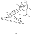
- FIG 1 shows a preferred embodiment of a security device according to the invention, whereby the invention is not limited to the embodiment described in detail hereafter.
- the security device is used for retaining at least one garment hanger 80 on a garment rail 20.
- one end of the garment rail 20 is mounted at the upper end of a vertical pole 30 by means of a mounting device 10.
- Another mounting device is used for mounting the other end of the garment rail to an opposite vertical pole (not shown).
- the garment hanger 80 comprises a hook 81 for hanging the hanger onto the rail 20. It further comprises a garment holder 82 for carrying a garment like trousers, a coat, dress or shirt (not shown). A plurality of hangers can be hung onto the garment rail, whereby only one hanger 80 close to the mounting device 10 is exemplarily shown in Figure 1 .
- the security device comprises a pivot-mounted lever 90 (90') which is mounted on each mounting device 10 (10').
- the lever pivots around a pivot point 91, whereby the bearing can easily be achieved by a pin and a bore, for example.
- a knob 92 can be provided for operating the lever 90.
- the shape of the lever 90 is curved. Thereby, when the lever 90 is pivoted around the pivot point 91 in the direction of the rail 20, it surrounds the garment rail 20 and the hook of the hanger 80, respectively, as it is shown in Figure 1 .
- the garment hanger 80 is retained on the rail 20 by a retaining bar 100 which is mounted between the two opposite levers 90 and 90'.
- the retaining bar 100 is a slim and light bar with a rubber surface which prevents garment hangers from falling and jumping off the rail 20 in transit.
- the two levers 90 and 90' are pivoted around their pivot point 91 (91') in the direction of the rail 20. In the operating position, the retaining bar 100 clamps the garment hangers to the rail 20, or a short distance between the retaining bar 100 and the hooks 81 of the hangers 80 is left.
- locking elements can be provided in each lever and mounting device, respectively.
- a resilient ball can be embedded in the outer surface of a mounting device 10.
- a corresponding bore is provided in the lever 90.
- the lever is locked in the locking position by a pin 93 which is inserted into a bore 94 in the mounting device.
- the bore 94, and therefore the pin 93 are located adjacent to the outer surface of the lever 90 in locking position. This can be gleaned from Figure 1 , where the lever 90 is in locking position and the pin 93 has been inserted. Since the pin 93 protrudes from the surface of the mounting device, the lever 90 is arrested by the pin and can not pivot back.
- Figure 2 shows the situation when the lever 90 has opened and the retaining bar 100 is moved away from the rail 20 and the hanger 80. Unless a resilient pin is chosen which can be pressed into the mounting device by operating the lever 90, the pin has to be removed from the bore 94 first. Then, a plurality of hangers 80 can be hung onto the rail 20 and the levers can be closed by using the knob 92, for example. Thereby, the retaining bar 100 covers all hooks of the hangers and as soon as the levers are locked by inserting the pin 93 in the bore 94, the retaining bar 100 prevents the hangers from falling off the rail 20. This situation is schematically shown in Figure 3 .
- FIG 4 shows a preferred embodiment of a mounting device used for mounting the security device to a vertical pole of a garment rail.
- This mounting device is composed of at least three members that are connected to each other in order to form a three-part mounting device.
- the mounting device has kind of a rectangular (cubic) shape, but any rounded shape can also be chosen.
- each of the two opposite members 40 and 50 forms the main body of the mounting device 10. Both members 40 and 50 basically have a cubic shape with several modifications of their general shape.
- each of the two opposite members 40 and 50 comprises a channel 41 and 51, respectively, with a semicircular cross-section embedded in a first surface 42 and 52 of the opposite members.
- the channels 41 and 51 have a semicircular cross-section in order to form a circular passage 12, when both opposite members 40 and 50 are connected via said first surfaces 42 and 52.
- a great part of the basic bodies of each of the opposite members has been cut out for forming each of the channels 41 and 51.
- the garment rail 20 with a circular cross-section can easily be inserted into this passage 12.
- the opposite members 40 and 50 each comprise another channel 43 and 53, respectively, with a quadrant cross-section at the edge connecting said first surface 42 and 52 to a second surface 44 and 54 of the opposite members 40 and 50, respectively.
- said second surface 44 and 54 is adjacent to the first surface 42 and 52 forming an edge.
- quadrant cross-section means that a quarter of a circle is cut out of the bodies of the opposite members 40 and 50 at the edge between said surfaces 44 and 42 (54 and 52).
- the second channels 43 and 53 cut off the edge between theses adjacent surfaces, and the channels 43 and 53 have a cross-section in the form of a quadrant.
- the two opposite members 40 and 50 can be connected in various ways.
- several pins and counterpart bores are provided in the first surfaces 42 and 52 of the opposite members. These pins and counterpart bores engage when they are plugged into each other.
- the connection is established by at least one tongue and a counterpart groove into which said tongue is inserted.
- two tongues 45 and 45' are mounted on the first surface 42 of the first member 40. Since most of its surface 42 is cut off by the channel 41, the tongues 45 and 45' are mounted on the remaining area of the surface 42. Thereby, they run in the direction of the longitudinal axis 11 of the resulting circular passage 12.
- the cross sections of the tongues 45 and 45' and the grooves 55 and 55' each have a hooked shape like shown in Figure 4 .
- the two opposite members 40 and 50 can be connected to each other by sliding the tongues 45 and 45' into the grooves 55 and 55' in the direction of the longitudinal axis 11 of the circular passage 12, like it is shown in Figure 5 . Because of the hooked shape of the connecting elements, the connection can not fall apart. The connection can only be released by sliding both members back.
- both members 40 and 50 are connected with or without an inserted bar, they are fixed by means of a third closing member 60.
- This third member of the mounting device 10 is connected to the second surfaces 44 and 54 of the opposite members 40 and 50.
- the closing member 60 also comprises a channel 61 with semicircular cross-section embedded in a third surface 62 of the closing member 60.
- a second circular passage 14 is formed, when the third surface 62 of the closing member 60 is connected to the second surfaces 44 and 54 of the two opposite members 40 and 50, respectively, because channel 61 of the closing member forms a circular passage 14 together with the channel resulting from connecting the quadrant channels of each opposite member.
- the longitudinal axis 11 of the first circular passage 12 lies perpendicularly to the longitudinal axis 13 of the second circular passage 14.
- connection of the third closing member 60 to the two opposite members 40 and 50 is also established by a tongue and groove connection.
- two tongues 64 and 64' can be formed in the surface 62 of the closing member, which engage with two grooves 46 and 56 on the side of the opposite members 40 and 50, or vice versa.
- the closing member 60 can be slided onto the opposite members 40 and 50 like it is shown in Figure 6 . Thereby, the lengths of the tongues 64 and 64' and the grooves 46 and 56 are smaller than the respective length of the surface 62.
- the mounting device 10 is looked at with the first circular passage 12 extending horizontally, the tongues and grooves of the closing member 60 are mounted in the upper area of the third surface 62 of the closing member 60.
- the closing member 60 can not slide down but is retained.
- a vertical pole can be inserted into the resulting second circular passage 14 before or after the closing member 60 is fixed to the connected opposite members 40 and 50.
- the mounting device 10 comprises means for fixing the mounting device to said vertical pole.
- the mounting device has to be fixed to the vertical pole in order to fasten the horizontal rail to the vertical pole.
- the means for fixing the vertical pole within the second passage 14 is an over centered lever 63 attached to the closing member 60, whereby operating the lever 63 clamps the device 10 to the vertical pole 30 by reducing the inner diameter of the second circular passage 14.
- the closing member 60 can comprise an open middle section 65 which provides for space for operating the over centered lever 63.
- the described mounting device is used for fixing at least one horizontal rail to two lateral vertical poles of a garment rail.
- Such garment rail 70 is schematically shown in Figure 8 .
- the garment rail 70 comprises at least two vertical poles 30 and 31 and a horizontal rail 21, which is connected to the lateral poles 30 and 31 at their upper ends. Long garments like trousers, coats, etc. can be hung onto the horizontal rail by means of hangers.
- the garment rail 70 can comprise another horizontal unit in form of a base unit 71 which is amounted at the lower ends of the vertical poles. Rolls 72 (72') can be attached to the base unit 71.
- At least one other second horizontal rail 20 can be connected to the vertical poles by means of two mounting devices 10 and 10'. Thereby, it is advantageous that the garment rail 70 does not have to be disassembled in order to fix the second horizontal rail.
- the second horizontal rail 20 can be positioned between the vertical poles 30 and 31. Then, the two opposite members of each mounting device are slided onto each other while the horizontal rail 20 is positioned in their semicircular channels. After that, the horizontal rail 20 is already fixed between the two vertical poles 30 31 and can be fixed to them in the chosen height by applying the closing members and operating the levers.
- the horizontal rail 20 can be inserted into the semicircular passages of each mounting device 10 and 10' and is then positioned and fixed between the two vertical poles 30 and 31.
- Further horizontal rails can be mounted in the same way. Shorter garments can be hung onto at least two rails which increases the capacity of the garment rail significantly. The height of the additional horizontal rail(s) can always be adjusted by releasing the lever and moving the horizontal rail to the desired height.
- the levers 90 and 90' can already be affixed to one of the opposite members 40, or it can retroactively be attached to the pivot point 91.
- a mounting device with an attached lever 90 can be seen in Figure 6 , for example.
- the retaining bar 100 can be attached to the levers like shown in Figure 7 . Therefore, bores can be provided in the levers and the retaining bar can be inserted in each of said bores. Once the retaining bar 100 is mounted, it can be operated like described before.
- the security device according to the invention and the mounting device can be used separately for different purposes.
- the combination of both members allows for secure transport of garments on a garment rail, whereby the height of the garment rail can easily be changed.
- additional garment rails can temporarily be mounted if required.
Landscapes
- Holders For Apparel And Elements Relating To Apparel (AREA)
Abstract
The invention relates to a security device for retaining garment hangers (80) on a horizontal garment rail (20;21), whereby a garment hanger (80) comprises a hook (81) for hanging the garment hanger (80) onto the garment rail (20;21), and the garment rail (20;21) is mounted between two lateral vertical poles (30;31) by means of a mounting device (10;10') at each end of the horizontal rail (20;21). According to the invention, a lever (90;90') is pivot-mounted on each of the mounting devices (10;10'), respectively, whereby the two levers (90;90') are connected by a horizontal retaining bar (100), and at least one of the pivoted levers (90;90') can be locked in a position in which the hooks (81) of the garment hangers (80) are retained by the retaining bar (100).
Description
- The invention relates to a security device for retaining garment hangers on a horizontal garment rail, whereby a garment hanger comprises a hook for hanging the garment hanger onto the garment rail. The garment rail is mounted between two lateral vertical poles by means of a mounting device at each end of the horizontal rail.
- Usually, garment rails are used for storage and transport of garments on hangers. A garment rail comprises at least one horizontal rail that is connected to two lateral vertical poles. The connection between the horizontal rail and the vertical poles can be established in different ways, whereby permanent or non-permanent connections can be used. Preferably, the horizontal rail is mounted at the upper ends of the vertical poles in order to allow long garments to hang down.
- Garments are hung onto the garment rail by means of garment hangers with hooks which are linked to the garment rail. However, when these loaded garment rails are transported by pulling them from one location to the other, for example, or by transporting them in trucks over a distance, garment hangers can drop off the garment rail.
- Therefore, it is an object of the invention to provide a security device for retaining garment hangers on a garment rail.
- According to the invention, this objective is achieved by a security device having the features of the independent Claim 1. Advantageous refinements of the security device are set forth in the subordinate Claims 2 through 14.
- According to the invention, a security device is used for retaining garment hangers on a horizontal garment rail. Thereby, a garment hanger comprises a hook for hanging the garment hanger onto the garment rail, and the garment rail is mounted between two lateral vertical poles by means of a mounting device at each end of the horizontal rail. A lever is pivot-mounted on each of the mounting devices, respectively, whereby the two levers are connected by a horizontal retaining bar, and at least one of the pivoted levers can be locked in a position in which the hooks of the garment hangers are retained by the retaining bar. Preferably, at least one lever has a knob for operating the lever.
- Preferably, each lever pivots around a pivot point and at least one of the pivoted levers can be locked by arresting a locking element of the lever with a counterpart locking element of the mounting device, respectively. The locking element of the lever can be a resilient ball, for example, whereas the counterpart locking element of the mounting device is a notch.
In another embodiment of the invention, each lever pivots around a pivot point and at least one of the pivoted levers can be locked by means of a pin that is inserted into a bore of the corresponding mounting device, whereby the bore is located adjacent to the outer surface of the lever when the lever is brought in locking position. - In a preferred embodiment of the invention, mounting devices are used which allow for an easy assembly of a garment rail with a security device. Thereby, each mounting device is composed of three members, whereby two opposite members are connected to each other and form the main body of the mounting device, whereby these opposite members each comprise a channel with a semicircular cross-section embedded in a first surface of the opposite members, and these channels form a first circular passage, when both members are connected via said first surface. Furthermore, the opposite members each comprise another channel with a quadrant cross-section at the edge connecting said first surface to a second surface, whereby these channels form a semicircular channel when both opposite members are connected via said first surface. A closing member is connected to said second surfaces of the opposite members, whereby the closing member comprises a channel with semicircular cross-section embedded in a third surface of the closing member, which forms a second circular passage, when the third surface of the closing member is connected to the second surfaces of the two opposite members, respectively. Thereby, the longitudinal axis of the first circular passage lies perpendicularly to the longitudinal axis of the second circular passage, whereby the garment rail can be inserted into the first circular passage and a lateral vertical pole can be inserted into the second circular passage. Furthermore, the mounting device comprises means for fixing the lateral vertical pole within the second passage.
- Preferably, the means for fixing the second bar within the second passage is an over centered lever mounted on the closing member, whereby operating said lever clamps the device to the second bar by reducing the inner diameter of the second circular passage.
- In a preferred embodiment of the invention, the two opposite members are connected to each other via their first surfaces by at least one salient connection element mounted on one member engaging with a counterpart notch in the opposite member. Said salient connection element can be a pin, for example, whereas the counterpart notch is a bore.
- Preferably, the salient connection element is a tongue, whereas the counterpart notch is a groove, and the tongue and the groove both run parallel to the longitudinal axis of the first circular passage. The tongue and the groove can have a hooked cross-section, and then the opposite members are connected to each other by sliding the tongue into the groove in the direction of the longitudinal axis of the first circular passage.
- Furthermore, the closing member can also be connected to the second surfaces of the two opposite members by at least one salient connection element mounted on the third surface of the closing member engaging with at least one counterpart notch in the second surfaces of the opposite members. The salient connection element can be a tongue, whereas the counterpart notch is a groove, and the tongue and the groove both run parallel to the longitudinal axis of the second circular passage.
- Preferably, the lengths of the tongue and the groove are smaller than the respective length of the third surface of the closing member.
- Advantages, special features and practical refinements of the invention can be gleaned from the subordinate claims and from the presentation below of preferred embodiments making reference to the figures.
- The figures show the following:
- Figure 1
- a schematic view of one embodiment of the security device according to the invention with a garment hanger hung onto a garment rail;
- Figure 2
- a security device as shown in
Figure 1 with open retaining bar; - Figure 3
- a security device as shown in
Figure 1 with locked retaining bar; - Figure 4
- three members of a three-part mounting device for a security device;
- Figure 5
- the connection between two opposite members of the mounting device shown in
Figure 4 ; - Figure 6
- a third closing member connecting the two opposite members of the mounting device shown in
Figure 4 ; - Figure 7
- the security device shown in
Figure 1 in connection with the mounting device shown inFigure 4 ; and - Figure 8
- a garment rail using two mounting devices and a security device.
-
Figure 1 shows a preferred embodiment of a security device according to the invention, whereby the invention is not limited to the embodiment described in detail hereafter. The security device is used for retaining at least onegarment hanger 80 on agarment rail 20. InFigure 1 , one end of thegarment rail 20 is mounted at the upper end of avertical pole 30 by means of amounting device 10. Another mounting device is used for mounting the other end of the garment rail to an opposite vertical pole (not shown). - The
garment hanger 80 comprises ahook 81 for hanging the hanger onto therail 20. It further comprises agarment holder 82 for carrying a garment like trousers, a coat, dress or shirt (not shown). A plurality of hangers can be hung onto the garment rail, whereby only onehanger 80 close to themounting device 10 is exemplarily shown inFigure 1 . - The security device comprises a pivot-mounted lever 90 (90') which is mounted on each mounting device 10 (10'). The lever pivots around a
pivot point 91, whereby the bearing can easily be achieved by a pin and a bore, for example. Aknob 92 can be provided for operating thelever 90. The shape of thelever 90 is curved. Thereby, when thelever 90 is pivoted around thepivot point 91 in the direction of therail 20, it surrounds thegarment rail 20 and the hook of thehanger 80, respectively, as it is shown inFigure 1 . - The
garment hanger 80 is retained on therail 20 by aretaining bar 100 which is mounted between the twoopposite levers 90 and 90'. Preferably, theretaining bar 100 is a slim and light bar with a rubber surface which prevents garment hangers from falling and jumping off therail 20 in transit. In order to operate theretaining bar 100, the twolevers 90 and 90' are pivoted around their pivot point 91 (91') in the direction of therail 20. In the operating position, the retainingbar 100 clamps the garment hangers to therail 20, or a short distance between the retainingbar 100 and thehooks 81 of thehangers 80 is left. - In order to lock a lever and the retaining bar in this position, locking elements can be provided in each lever and mounting device, respectively. For example, a resilient ball can be embedded in the outer surface of a mounting
device 10. A corresponding bore is provided in thelever 90. When the lever is operated, the lever passes the resilient ball and presses it into the body of the mountingdevice 10. Once the bore of the lever has passed the resilient ball, the ball springs back and engages with the bore. The resilience of the ball has to be chosen accordingly. If the resilience is too low, the lever can unlock during transit. If the resilience is too high, it will be hard to lock the lever in the locking position. - In another embodiment of the invention, the lever is locked in the locking position by a
pin 93 which is inserted into abore 94 in the mounting device. Thebore 94, and therefore thepin 93, are located adjacent to the outer surface of thelever 90 in locking position. This can be gleaned fromFigure 1 , where thelever 90 is in locking position and thepin 93 has been inserted. Since thepin 93 protrudes from the surface of the mounting device, thelever 90 is arrested by the pin and can not pivot back. -
Figure 2 shows the situation when thelever 90 has opened and the retainingbar 100 is moved away from therail 20 and thehanger 80. Unless a resilient pin is chosen which can be pressed into the mounting device by operating thelever 90, the pin has to be removed from thebore 94 first. Then, a plurality ofhangers 80 can be hung onto therail 20 and the levers can be closed by using theknob 92, for example. Thereby, the retainingbar 100 covers all hooks of the hangers and as soon as the levers are locked by inserting thepin 93 in thebore 94, the retainingbar 100 prevents the hangers from falling off therail 20. This situation is schematically shown inFigure 3 . -
Figure 4 shows a preferred embodiment of a mounting device used for mounting the security device to a vertical pole of a garment rail. This mounting device is composed of at least three members that are connected to each other in order to form a three-part mounting device. Preferably, the mounting device has kind of a rectangular (cubic) shape, but any rounded shape can also be chosen. - Two
opposite members device 10. Bothmembers opposite members channel 41 and 51, respectively, with a semicircular cross-section embedded in afirst surface channels 41 and 51 have a semicircular cross-section in order to form acircular passage 12, when bothopposite members Figure 4 , a great part of the basic bodies of each of the opposite members has been cut out for forming each of thechannels 41 and 51. Thegarment rail 20 with a circular cross-section can easily be inserted into thispassage 12. - Furthermore, the
opposite members channel first surface second surface opposite members second surface first surface opposite members surfaces 44 and 42 (54 and 52). Thesecond channels channels opposite members first surfaces channels circular passage 12 which is formed when the opposite members are connected to each other. - The two
opposite members first surfaces tongues 45 and 45' are mounted on thefirst surface 42 of thefirst member 40. Since most of itssurface 42 is cut off by thechannel 41, thetongues 45 and 45' are mounted on the remaining area of thesurface 42. Thereby, they run in the direction of thelongitudinal axis 11 of the resultingcircular passage 12. - In the
opposite member 50,counterpart grooves 55 and 55' are embedded in itsfirst surface 52. Naturally, the cross section of thetongues 45 and 45' corresponds to the cross section of thegrooves 55 and 55' on theopposite member 40. In one further preferred embodiment of the invention, the cross sections of thetongues 45 and 45' and thegrooves 55 and 55' each have a hooked shape like shown inFigure 4 . Thereby, the twoopposite members tongues 45 and 45' into thegrooves 55 and 55' in the direction of thelongitudinal axis 11 of thecircular passage 12, like it is shown inFigure 5 . Because of the hooked shape of the connecting elements, the connection can not fall apart. The connection can only be released by sliding both members back. - As mentioned before, when the two
opposite members semicircular channels 41 and 51 form thecircular passage 12. The end of a garment rail with circular cross-section can now be inserted into this passage12. Alternatively, the end of the rail can be placed in thesemicircular channel 41 of thefirst member 40. Then, thesecond member 50 is slided onto the tongues of thefirst member 40 in the direction of the longitudinal axis of the rail which is also thelongitudinal axis 11 of thefirst passage 12. - When both
members third closing member 60. This third member of the mountingdevice 10 is connected to thesecond surfaces opposite members member 60 also comprises achannel 61 with semicircular cross-section embedded in athird surface 62 of the closingmember 60. When the closingmember 60 is connected to the twoopposite members circular passage 14 is formed, when thethird surface 62 of the closingmember 60 is connected to thesecond surfaces opposite members channel 61 of the closing member forms acircular passage 14 together with the channel resulting from connecting the quadrant channels of each opposite member. Thereby, thelongitudinal axis 11 of the firstcircular passage 12 lies perpendicularly to thelongitudinal axis 13 of the secondcircular passage 14. - Preferably, the connection of the
third closing member 60 to the twoopposite members tongues 64 and 64' can be formed in thesurface 62 of the closing member, which engage with twogrooves opposite members member 60 can be slided onto theopposite members Figure 6 . Thereby, the lengths of thetongues 64 and 64' and thegrooves surface 62. When the mountingdevice 10 is looked at with the firstcircular passage 12 extending horizontally, the tongues and grooves of the closingmember 60 are mounted in the upper area of thethird surface 62 of the closingmember 60. Thus, the closingmember 60 can not slide down but is retained. - A vertical pole can be inserted into the resulting second
circular passage 14 before or after the closingmember 60 is fixed to the connectedopposite members device 10 comprises means for fixing the mounting device to said vertical pole. The mounting device has to be fixed to the vertical pole in order to fasten the horizontal rail to the vertical pole. In one embodiment of the invention, the means for fixing the vertical pole within thesecond passage 14 is an over centered lever 63 attached to the closingmember 60, whereby operating the lever 63 clamps thedevice 10 to thevertical pole 30 by reducing the inner diameter of the secondcircular passage 14. Thereby, the closingmember 60 can comprise an openmiddle section 65 which provides for space for operating the over centered lever 63. - Preferably, the described mounting device is used for fixing at least one horizontal rail to two lateral vertical poles of a garment rail.
Such garment rail 70 is schematically shown inFigure 8 . Thegarment rail 70 comprises at least twovertical poles horizontal rail 21, which is connected to thelateral poles garment rail 70 can comprise another horizontal unit in form of abase unit 71 which is amounted at the lower ends of the vertical poles. Rolls 72 (72') can be attached to thebase unit 71. - If smaller garments have to be transported/stored, at least one other second
horizontal rail 20 can be connected to the vertical poles by means of two mountingdevices 10 and 10'. Thereby, it is advantageous that thegarment rail 70 does not have to be disassembled in order to fix the second horizontal rail. The secondhorizontal rail 20 can be positioned between thevertical poles horizontal rail 20 is positioned in their semicircular channels. After that, thehorizontal rail 20 is already fixed between the twovertical poles 30 31 and can be fixed to them in the chosen height by applying the closing members and operating the levers. Alternatively, thehorizontal rail 20 can be inserted into the semicircular passages of each mountingdevice 10 and 10' and is then positioned and fixed between the twovertical poles - Further horizontal rails can be mounted in the same way. Shorter garments can be hung onto at least two rails which increases the capacity of the garment rail significantly. The height of the additional horizontal rail(s) can always be adjusted by releasing the lever and moving the horizontal rail to the desired height.
- The
levers 90 and 90' can already be affixed to one of theopposite members 40, or it can retroactively be attached to thepivot point 91. A mounting device with an attachedlever 90 can be seen inFigure 6 , for example. When both levers 90 and 90' are attached to their mounting devices, the retainingbar 100 can be attached to the levers like shown inFigure 7 . Therefore, bores can be provided in the levers and the retaining bar can be inserted in each of said bores. Once the retainingbar 100 is mounted, it can be operated like described before. - The security device according to the invention and the mounting device can be used separately for different purposes. However, the combination of both members allows for secure transport of garments on a garment rail, whereby the height of the garment rail can easily be changed. Furthermore, additional garment rails can temporarily be mounted if required.
-
- 10,10'
- mounting device
- 11
- longitudinal axis
- 12
- first passage
- 13
- longitudinal axis
- 14
- second passage
- 20,21
- bar, horizontal rail
- 30,31
- bar, vertical pole
- 40
- first opposite member
- 41
- semicircular channel
- 42
- first surface
- 43
- quadrant channel
- 44
- second surface
- 45,45'
- connecting element, pin, tongue
- 46
- connecting element, groove
- 50
- second opposite member
- 51
- semicircular channel
- 52
- first surface
- 53
- quadrant channel
- 54
- second surface
- 55,55'
- notch, groove
- 56
- connecting element, groove
- 60
- closing member
- 61
- semicircular channel
- 62
- third surface
- 63
- lever
- 64,64'
- connecting element, tongue
- 65
- open middle section
- 70
- garment rail
- 71
- base unit
- 72,72'
- roll
- 80
- garment hanger
- 81
- hook
- 82
- garment holder
- 90,90'
- lever
- 91,91'
- pivot point
- 92
- knob
- 93
- pin
- 94
- bore
- 100
- retaining bar
Claims (14)
- Security device for retaining garment hangers (80) on a horizontal garment rail (20;21), whereby a garment hanger (80) comprises a hook (81) for hanging the garment hanger (80) onto the garment rail (20;21), and the garment rail (20;21) is mounted between two lateral vertical poles (30;31) by means of a mounting device (10;10') at each end of the horizontal rail (20;21),
characterized in that,
a lever (90;90') is pivot-mounted on each of the mounting devices (10;10'), respectively, whereby the two levers (90;90') are connected by a horizontal retaining bar (100), and at least one of the pivoted levers (90;90') can be locked in a position in which the hooks (81) of the garment hangers (80) are retained by the retaining bar (100). - Security device according to Claim 1,
characterized in that,
each lever (90;90') pivots around a pivot point (91;91') and at least one of the pivoted levers (90;90') can be locked by arresting a locking element of the lever (90;90') with a counterpart locking element of the mounting device (10;10'), respectively. - Security device according to Claim 2,
characterized in that,
the locking element of the lever (90;90') is a resilient ball, whereas the counterpart locking element of the mounting device (10;10') is a notch. - Security device according to Claim 1,
characterized in that,
each lever (90;90') pivots around a pivot point (91;91') and at least one of the pivoted levers (90;90') can be locked by means of a pin (93) that is inserted into a bore (94) of the corresponding mounting device (10;10'), whereby the bore (94) is located adjacent to the outer surface of the lever (90;90') when the lever (90;90') is brought in locking position. - Security device according to one of Claims 1 to 4,
characterized in that,
at least one lever (90;90') has a knob (92) for operating the lever (90;90'). - Security device according to one of Claims 1 to 5,
characterized in that,
each mounting device (10;10') is composed of three members (40;50;60), whereby two opposite members (40;50) are connected to each other and form the main body of the mounting device (10;10'), and these opposite members (40;50) each comprise a channel (41;51) with a semicircular cross-section embedded in a first surface (42;52) of the opposite members (40;50), and these channels (41;51) form a first circular passage (12), when both members (40;50) are connected via said first surface (42;52), and whereby the opposite members (40;50) each comprise another channel (43;53) with a quadrant cross-section at the edge connecting said first surface (42;52) to a second surface (44;54), and these channels (43;53) form a semicircular channel when both opposite members (40;50) are connected via said first surface (42;52), and a closing member (60) is connected to said second surfaces (44;54) of the opposite members (40;50), whereby the closing member (60) comprises a channel (61) with semicircular cross-section embedded in a third surface (62) of the closing member (60), which forms a second circular passage (14), when the third surface (62) of the closing member (60) is connected to the second surfaces (44;54) of the two opposite members (40;50), respectively, and the longitudinal axis (11) of the first circular passage (12) lies perpendicularly to the longitudinal axis (13) of the second circular passage (14), whereby the garment rail (20) can be inserted into the first circular passage (12) and a lateral vertical pole (30;31) can be inserted into the second circular passage (14), and the mounting device (10;10') comprises means for fixing the lateral vertical pole (30;31) within the second passage (14). - Security device according to Claim 6,
characterized in that,
the means for fixing the second bar (30;31) within the second passage (14) is an over centered lever (63) mounted on the closing member (60), whereby operating said lever (63) clamps the device (10) to the second bar (30) by reducing the inner diameter of the second circular passage (14). - Security device according to one of Claims 6 and 7,
characterized in that,
the two opposite members (40;50) are connected to each other via their first surfaces (42;52) by at least one salient connection element (45;45') mounted on one member (40) engaging with a counterpart notch (55;55') in the opposite member (50). - Security device according to Claim 8,
characterized in that,
the salient connection element is a pin, whereas the counterpart notch is a bore. - Security device according to Claim 9,
characterized in that,
the salient connection element is a tongue (45;45'), whereas the counterpart notch is a groove (55;55'), and the tongue (45:45') and the groove (55;55') both run parallel to the longitudinal axis (11) of the first circular passage (12). - Security device according to Claim 10,
characterized in that,
the tongue (45;45') and the groove (55;55') have a hooked cross-section, and the opposite members (40;50) are connected to each other by sliding the tongue (45;45') into the groove (55;55') in the direction of the longitudinal axis (11) of the first circular passage (12). - Security device according to one of Claims 6 to 11,
characterized in that,
the closing member (60) is connected to the second surfaces (44;54) of the two opposite members (40;50) by at least one salient connection element (64;64') mounted on the third surface (62) of the closing member (60) engaging with at least one counterpart notch (46;56) in the second surfaces (44;54) of the opposite members (40;50). - Security device according to Claim 12,
characterized in that,
the salient connection element is a tongue (64;64), whereas the counterpart notch is a groove (46;56), and the tongue (64;64) and the groove (46;56) both run parallel to the longitudinal axis (13) of the second circular passage (14). - Security device according to Claim 13,
characterized in that,
the lengths of the tongue (64;64) and the groove (46;56) are smaller than the respective length of the third surface (62) of the closing member (60).
Priority Applications (1)
| Application Number | Priority Date | Filing Date | Title |
|---|---|---|---|
| EP08022539A EP2204520A1 (en) | 2008-12-31 | 2008-12-31 | Security device for garment rails |
Applications Claiming Priority (1)
| Application Number | Priority Date | Filing Date | Title |
|---|---|---|---|
| EP08022539A EP2204520A1 (en) | 2008-12-31 | 2008-12-31 | Security device for garment rails |
Publications (1)
| Publication Number | Publication Date |
|---|---|
| EP2204520A1 true EP2204520A1 (en) | 2010-07-07 |
Family
ID=40651796
Family Applications (1)
| Application Number | Title | Priority Date | Filing Date |
|---|---|---|---|
| EP08022539A Ceased EP2204520A1 (en) | 2008-12-31 | 2008-12-31 | Security device for garment rails |
Country Status (1)
| Country | Link |
|---|---|
| EP (1) | EP2204520A1 (en) |
Cited By (4)
| Publication number | Priority date | Publication date | Assignee | Title |
|---|---|---|---|---|
| CN102776767A (en) * | 2012-07-26 | 2012-11-14 | 许文强 | Combined type clothes hanger improvement structure |
| CN102776758A (en) * | 2012-07-26 | 2012-11-14 | 许文强 | Clothes airing rod |
| US20160198849A1 (en) * | 2015-01-08 | 2016-07-14 | Clairson, Inc. | Closet Storage Assemblies, Connectors, Brackets and Systems |
| USD803673S1 (en) | 2015-01-08 | 2017-11-28 | Clairson, Inc. | T-connector for a closet storage assembly |
Citations (6)
| Publication number | Priority date | Publication date | Assignee | Title |
|---|---|---|---|---|
| US1975543A (en) * | 1933-07-17 | 1934-10-02 | Carl W Giessler | Tie rack |
| AT176150B (en) * | 1952-05-29 | 1953-09-25 | Ferdinand Ondracek | Protection device against theft for clothing stands |
| US2868390A (en) * | 1955-10-25 | 1959-01-13 | Yankee Engineering Company Inc | Locking device for clothes hangers |
| US3735875A (en) * | 1971-03-17 | 1973-05-29 | Stores B Inc New York | Security device for clothes racks |
| EP0035725A1 (en) * | 1980-03-06 | 1981-09-16 | Gebr. Titgemeyer GmbH & Co. KG | Device for firmly securing clothes hangers to carrying rods |
| US5785184A (en) * | 1994-05-10 | 1998-07-28 | Metselaar; Herbert | Stand with hangers for items of clothing |
-
2008
- 2008-12-31 EP EP08022539A patent/EP2204520A1/en not_active Ceased
Patent Citations (6)
| Publication number | Priority date | Publication date | Assignee | Title |
|---|---|---|---|---|
| US1975543A (en) * | 1933-07-17 | 1934-10-02 | Carl W Giessler | Tie rack |
| AT176150B (en) * | 1952-05-29 | 1953-09-25 | Ferdinand Ondracek | Protection device against theft for clothing stands |
| US2868390A (en) * | 1955-10-25 | 1959-01-13 | Yankee Engineering Company Inc | Locking device for clothes hangers |
| US3735875A (en) * | 1971-03-17 | 1973-05-29 | Stores B Inc New York | Security device for clothes racks |
| EP0035725A1 (en) * | 1980-03-06 | 1981-09-16 | Gebr. Titgemeyer GmbH & Co. KG | Device for firmly securing clothes hangers to carrying rods |
| US5785184A (en) * | 1994-05-10 | 1998-07-28 | Metselaar; Herbert | Stand with hangers for items of clothing |
Cited By (5)
| Publication number | Priority date | Publication date | Assignee | Title |
|---|---|---|---|---|
| CN102776767A (en) * | 2012-07-26 | 2012-11-14 | 许文强 | Combined type clothes hanger improvement structure |
| CN102776758A (en) * | 2012-07-26 | 2012-11-14 | 许文强 | Clothes airing rod |
| US20160198849A1 (en) * | 2015-01-08 | 2016-07-14 | Clairson, Inc. | Closet Storage Assemblies, Connectors, Brackets and Systems |
| US9498058B2 (en) * | 2015-01-08 | 2016-11-22 | Clairson, Inc. | Closet storage assemblies, connectors, brackets and systems |
| USD803673S1 (en) | 2015-01-08 | 2017-11-28 | Clairson, Inc. | T-connector for a closet storage assembly |
Similar Documents
| Publication | Publication Date | Title |
|---|---|---|
| JP5437656B2 (en) | clothes hanger | |
| US9255602B2 (en) | Systems and methods for a locking double carabineer | |
| US20100264101A1 (en) | Multiple Purpose Handbag Hanger | |
| US6875392B2 (en) | Coordinate loop garment hanger | |
| US9441665B2 (en) | Systems and methods for a locking carabineer | |
| US20120060399A1 (en) | Esl locking mechanism | |
| US9377134B2 (en) | Hanger for an elongate article | |
| US4204601A (en) | Security display rack | |
| CN107979980A (en) | Universal device for suitcases, with sliding inner frame for hanging clothes hangers | |
| EP0330653A1 (en) | Security device for trolleys | |
| US20050155946A1 (en) | Hanging device | |
| US20160198849A1 (en) | Closet Storage Assemblies, Connectors, Brackets and Systems | |
| EP2204588A1 (en) | Mounting device and garment rail using mounting device | |
| US20050274685A1 (en) | Store fixture with swing arms | |
| US7513375B2 (en) | Hanging device | |
| KR20100094150A (en) | Auxiliary apparatus for diagonal clothes hanger | |
| US10094064B2 (en) | Portable drying rack | |
| US8544806B1 (en) | System for mounting items to a wall | |
| CN110861881A (en) | Lock and hanging device | |
| CN105984250A (en) | Annular binder with interlocking annular members | |
| US6206209B1 (en) | Secure belt and tie holder device | |
| GB2457428A (en) | A clothes hanger rack | |
| US6962261B2 (en) | System for frontal display of objects | |
| US20140312080A1 (en) | Method and apparatus for clothes hanger device | |
| CN102008219B (en) | Anti-skidding clothes racks |
Legal Events
| Date | Code | Title | Description |
|---|---|---|---|
| PUAI | Public reference made under article 153(3) epc to a published international application that has entered the european phase |
Free format text: ORIGINAL CODE: 0009012 |
|
| AK | Designated contracting states |
Kind code of ref document: A1 Designated state(s): AT BE BG CH CY CZ DE DK EE ES FI FR GB GR HR HU IE IS IT LI LT LU LV MC MT NL NO PL PT RO SE SI SK TR |
|
| AX | Request for extension of the european patent |
Extension state: AL BA MK RS |
|
| STAA | Information on the status of an ep patent application or granted ep patent |
Free format text: STATUS: THE APPLICATION HAS BEEN REFUSED |
|
| 18R | Application refused |
Effective date: 20100810 |