EP2204465A2 - Apparatus for reducing stress when applying coatings, processes for applying the same and their coated articles - Google Patents
Apparatus for reducing stress when applying coatings, processes for applying the same and their coated articles Download PDFInfo
- Publication number
- EP2204465A2 EP2204465A2 EP09252237A EP09252237A EP2204465A2 EP 2204465 A2 EP2204465 A2 EP 2204465A2 EP 09252237 A EP09252237 A EP 09252237A EP 09252237 A EP09252237 A EP 09252237A EP 2204465 A2 EP2204465 A2 EP 2204465A2
- Authority
- EP
- European Patent Office
- Prior art keywords
- axially split
- split component
- coating
- engagement surface
- applying
- Prior art date
- Legal status (The legal status is an assumption and is not a legal conclusion. Google has not performed a legal analysis and makes no representation as to the accuracy of the status listed.)
- Granted
Links
- 238000000576 coating method Methods 0.000 title claims abstract description 78
- 238000000034 method Methods 0.000 title claims abstract description 27
- 230000008569 process Effects 0.000 title claims abstract description 19
- 239000011248 coating agent Substances 0.000 claims abstract description 58
- 230000008602 contraction Effects 0.000 claims abstract description 33
- 239000011247 coating layer Substances 0.000 claims description 6
- 238000004140 cleaning Methods 0.000 claims description 5
- 230000007423 decrease Effects 0.000 claims description 3
- 230000000873 masking effect Effects 0.000 claims description 2
- 238000003754 machining Methods 0.000 claims 1
- 230000008859 change Effects 0.000 abstract description 4
- 239000000463 material Substances 0.000 description 19
- 239000007921 spray Substances 0.000 description 8
- 238000005507 spraying Methods 0.000 description 8
- 239000002245 particle Substances 0.000 description 6
- PXHVJJICTQNCMI-UHFFFAOYSA-N Nickel Chemical compound [Ni] PXHVJJICTQNCMI-UHFFFAOYSA-N 0.000 description 5
- 238000005452 bending Methods 0.000 description 5
- 239000000203 mixture Substances 0.000 description 5
- 239000011651 chromium Substances 0.000 description 4
- 239000010410 layer Substances 0.000 description 4
- 238000012496 stress study Methods 0.000 description 4
- 238000009792 diffusion process Methods 0.000 description 3
- VYZAMTAEIAYCRO-UHFFFAOYSA-N Chromium Chemical compound [Cr] VYZAMTAEIAYCRO-UHFFFAOYSA-N 0.000 description 2
- XEEYBQQBJWHFJM-UHFFFAOYSA-N Iron Chemical compound [Fe] XEEYBQQBJWHFJM-UHFFFAOYSA-N 0.000 description 2
- 229920005479 Lucite® Polymers 0.000 description 2
- XAGFODPZIPBFFR-UHFFFAOYSA-N aluminium Chemical compound [Al] XAGFODPZIPBFFR-UHFFFAOYSA-N 0.000 description 2
- 229910052804 chromium Inorganic materials 0.000 description 2
- 238000005253 cladding Methods 0.000 description 2
- 229910017052 cobalt Inorganic materials 0.000 description 2
- 239000010941 cobalt Substances 0.000 description 2
- GUTLYIVDDKVIGB-UHFFFAOYSA-N cobalt atom Chemical compound [Co] GUTLYIVDDKVIGB-UHFFFAOYSA-N 0.000 description 2
- 230000000694 effects Effects 0.000 description 2
- 238000010438 heat treatment Methods 0.000 description 2
- 229910052759 nickel Inorganic materials 0.000 description 2
- BASFCYQUMIYNBI-UHFFFAOYSA-N platinum Chemical compound [Pt] BASFCYQUMIYNBI-UHFFFAOYSA-N 0.000 description 2
- 239000004926 polymethyl methacrylate Substances 0.000 description 2
- 230000001737 promoting effect Effects 0.000 description 2
- 230000002829 reductive effect Effects 0.000 description 2
- 238000007711 solidification Methods 0.000 description 2
- 230000008023 solidification Effects 0.000 description 2
- 239000000758 substrate Substances 0.000 description 2
- 229910052727 yttrium Inorganic materials 0.000 description 2
- VWQVUPCCIRVNHF-UHFFFAOYSA-N yttrium atom Chemical compound [Y] VWQVUPCCIRVNHF-UHFFFAOYSA-N 0.000 description 2
- 229910000838 Al alloy Inorganic materials 0.000 description 1
- 229910052582 BN Inorganic materials 0.000 description 1
- PZNSFCLAULLKQX-UHFFFAOYSA-N Boron nitride Chemical compound N#B PZNSFCLAULLKQX-UHFFFAOYSA-N 0.000 description 1
- OKTJSMMVPCPJKN-UHFFFAOYSA-N Carbon Chemical compound [C] OKTJSMMVPCPJKN-UHFFFAOYSA-N 0.000 description 1
- 229910000881 Cu alloy Inorganic materials 0.000 description 1
- 229910002543 FeCrAlY Inorganic materials 0.000 description 1
- 229910000990 Ni alloy Inorganic materials 0.000 description 1
- 239000004372 Polyvinyl alcohol Substances 0.000 description 1
- 229910000676 Si alloy Inorganic materials 0.000 description 1
- 230000001464 adherent effect Effects 0.000 description 1
- 229910045601 alloy Inorganic materials 0.000 description 1
- 239000000956 alloy Substances 0.000 description 1
- CSDREXVUYHZDNP-UHFFFAOYSA-N alumanylidynesilicon Chemical compound [Al].[Si] CSDREXVUYHZDNP-UHFFFAOYSA-N 0.000 description 1
- 229910052782 aluminium Inorganic materials 0.000 description 1
- 230000004323 axial length Effects 0.000 description 1
- 239000000440 bentonite Substances 0.000 description 1
- 229910000278 bentonite Inorganic materials 0.000 description 1
- SVPXDRXYRYOSEX-UHFFFAOYSA-N bentoquatam Chemical compound O.O=[Si]=O.O=[Al]O[Al]=O SVPXDRXYRYOSEX-UHFFFAOYSA-N 0.000 description 1
- 238000002485 combustion reaction Methods 0.000 description 1
- 239000002131 composite material Substances 0.000 description 1
- 239000000470 constituent Substances 0.000 description 1
- 238000005336 cracking Methods 0.000 description 1
- 230000032798 delamination Effects 0.000 description 1
- 230000001419 dependent effect Effects 0.000 description 1
- 238000000151 deposition Methods 0.000 description 1
- 230000008021 deposition Effects 0.000 description 1
- 238000005137 deposition process Methods 0.000 description 1
- 238000005328 electron beam physical vapour deposition Methods 0.000 description 1
- 238000010894 electron beam technology Methods 0.000 description 1
- 238000005516 engineering process Methods 0.000 description 1
- 230000007613 environmental effect Effects 0.000 description 1
- 239000000945 filler Substances 0.000 description 1
- 239000010439 graphite Substances 0.000 description 1
- 229910002804 graphite Inorganic materials 0.000 description 1
- 229910052735 hafnium Inorganic materials 0.000 description 1
- VBJZVLUMGGDVMO-UHFFFAOYSA-N hafnium atom Chemical compound [Hf] VBJZVLUMGGDVMO-UHFFFAOYSA-N 0.000 description 1
- 238000010286 high velocity air fuel Methods 0.000 description 1
- 238000007749 high velocity oxygen fuel spraying Methods 0.000 description 1
- 229910010272 inorganic material Inorganic materials 0.000 description 1
- 239000011147 inorganic material Substances 0.000 description 1
- 238000009434 installation Methods 0.000 description 1
- 230000002452 interceptive effect Effects 0.000 description 1
- 229910052742 iron Inorganic materials 0.000 description 1
- 230000000670 limiting effect Effects 0.000 description 1
- 229910052751 metal Inorganic materials 0.000 description 1
- 239000002184 metal Substances 0.000 description 1
- 239000007769 metal material Substances 0.000 description 1
- 230000004048 modification Effects 0.000 description 1
- 238000012986 modification Methods 0.000 description 1
- 230000007935 neutral effect Effects 0.000 description 1
- 239000011368 organic material Substances 0.000 description 1
- 230000003647 oxidation Effects 0.000 description 1
- 238000007254 oxidation reaction Methods 0.000 description 1
- 229910052697 platinum Inorganic materials 0.000 description 1
- 229920000728 polyester Polymers 0.000 description 1
- 229920000642 polymer Polymers 0.000 description 1
- 229920002451 polyvinyl alcohol Polymers 0.000 description 1
- 238000002360 preparation method Methods 0.000 description 1
- 230000000284 resting effect Effects 0.000 description 1
- 238000004544 sputter deposition Methods 0.000 description 1
- 230000007704 transition Effects 0.000 description 1
Images







Classifications
-
- C—CHEMISTRY; METALLURGY
- C23—COATING METALLIC MATERIAL; COATING MATERIAL WITH METALLIC MATERIAL; CHEMICAL SURFACE TREATMENT; DIFFUSION TREATMENT OF METALLIC MATERIAL; COATING BY VACUUM EVAPORATION, BY SPUTTERING, BY ION IMPLANTATION OR BY CHEMICAL VAPOUR DEPOSITION, IN GENERAL; INHIBITING CORROSION OF METALLIC MATERIAL OR INCRUSTATION IN GENERAL
- C23C—COATING METALLIC MATERIAL; COATING MATERIAL WITH METALLIC MATERIAL; SURFACE TREATMENT OF METALLIC MATERIAL BY DIFFUSION INTO THE SURFACE, BY CHEMICAL CONVERSION OR SUBSTITUTION; COATING BY VACUUM EVAPORATION, BY SPUTTERING, BY ION IMPLANTATION OR BY CHEMICAL VAPOUR DEPOSITION, IN GENERAL
- C23C4/00—Coating by spraying the coating material in the molten state, e.g. by flame, plasma or electric discharge
- C23C4/02—Pretreatment of the material to be coated, e.g. for coating on selected surface areas
-
- C—CHEMISTRY; METALLURGY
- C23—COATING METALLIC MATERIAL; COATING MATERIAL WITH METALLIC MATERIAL; CHEMICAL SURFACE TREATMENT; DIFFUSION TREATMENT OF METALLIC MATERIAL; COATING BY VACUUM EVAPORATION, BY SPUTTERING, BY ION IMPLANTATION OR BY CHEMICAL VAPOUR DEPOSITION, IN GENERAL; INHIBITING CORROSION OF METALLIC MATERIAL OR INCRUSTATION IN GENERAL
- C23C—COATING METALLIC MATERIAL; COATING MATERIAL WITH METALLIC MATERIAL; SURFACE TREATMENT OF METALLIC MATERIAL BY DIFFUSION INTO THE SURFACE, BY CHEMICAL CONVERSION OR SUBSTITUTION; COATING BY VACUUM EVAPORATION, BY SPUTTERING, BY ION IMPLANTATION OR BY CHEMICAL VAPOUR DEPOSITION, IN GENERAL
- C23C4/00—Coating by spraying the coating material in the molten state, e.g. by flame, plasma or electric discharge
Definitions
- the invention relates to coatings and, more particularly, relates to reducing stress when thermal spray coatings to turbine engine components.
- thermal spray coatings When applying thermal spray coatings to the internal surfaces of axially split components such as fan casings, high energy thermal plasma spray techniques are commonly employed. During the coating processes, the high thermal energy and high coating application temperatures cause the residual stress in the coating and fan casing halves to distort. The resultant stress affects the quality and service life of the abradable coating. The thermal spray coating cracks and may spall or peel during use. As a result, cracked abradable coatings also affect the useful service life of the fan casing.
- a process for applying a coating to an axially split component broadly comprises installing at least one expansion device to at least one half of an axially split component; expanding the at least one half to increase a radius of curvature of and preferably maintain a constant curvature of said at least one half; applying at least one coating layer to said at least a portion of said at least one half; and removing at least one expansion device from said at least one half.
- an expansion device for use in forming an axially split component broadly comprises a wedge-block shaped body; a first end; a second end disposed opposite the first end; and a tapered angle formed at an angle positively with respect to the inboard surface using the first end as a point of reference.
- a process for applying a coating to an axially split component broadly comprises installing at least one contraction device to at least one half of an axially split component; contracting at least one half to decrease a radius of curvature of and preferably maintain a constant curvature of said at least one half; applying at least one coating layer to said at least a portion of said at least one half; and removing at least one contraction device from said at least one half.
- a contraction device for use in forming an axially split component broadly comprises a wedge-block shaped body; a first end; a second end disposed opposite the first end; and a tapered angle formed at an angle negatively with respect to the inboard surface using the first end as a point of reference.
- FIGS. 1-8 an exemplary expansion device for use in applying coatings to axially split components is now described in detail. Although there are many examples of axially split components to select, the exemplary expansion device will be explained with regard to a split fan casing of a gas turbine engine.
- the expansion device 10 may comprise a wedge-block shaped body (see cross-sectional view of FIG. 2 ) having an inboard surface 12 and an outboard surface 14 disposed opposite each other along with a first engagement surface 16 and a second engagement surface 18 disposed opposite each other.
- the respective surfaces 12, 14, 16 and 18 being connected together to form the wedge-block shaped body having a first end 17, a second end 19 and a conical angle 21 as shown in FIG. 1 .
- a tapered angle may be formed at a positive angle with respect to the inboard surface 12.
- the inboard surface 12 may include a plurality of intersection points 20, 22, 24 and 26 formed at the juncture of several portions of the inboard surface 12, for example, a first conical portion 30, a second conical portion 32, a third portion 34, a fourth portion 36 and a fifth portion 38.
- Each intersection point may also be associated with a change in angle, such that a first angle 40 may be formed about the inboard surface 12 at the first intersection point 20 of the first conical portion 30 and the second conical portion 32 using the first conical portion 30 as a point of reference.
- a second angle 44 may be formed inversely, that is, a negative angle as shown in FIG.
- a third angle 48 may be formed about the inboard surface 12 at a third intersection point 24 of the third portion 34 and the fourth portion 36 using the third portion 34 as a point of reference.
- a fourth angle 52 may be formed inversely about the inboard surface 12 at a fourth intersection point 26 of the fourth portion 36 and the fifth portion 38 using the fifth portion 38 as a point of reference. All of these angles are associated with a change in diameter of the split component along the axial length. The angle of the wedge remains constant, while the chord lengths of surfaces 12 and 14 vary proportionally to the diameter of the part at each axial location.
- the inboard, first engagement and second engagement surfaces 12, 16 and 18 may possess dimensions that are approximated as an average of all the angles.
- the purpose of the inboard, first engagement and second engagement surfaces are to prevent the device from interfering with the coating process(es).
- the intersection points may be generalized collectively such that the shape and dimensions of the expansion device may change dependent upon the axially split component being coated.
- the expansion device may exhibit a cylindrical shape or progress to exhibit a simple conical shape or progress to a complex set of dimensions as described above.
- the first engagement surface 16 and second engagement surface 18 may include a plurality of apertures 56 disposed through the first engagement surface 16 to the second engagement surface 18 for receiving means for attachment 58 such as bolts and other devices, instrument, parts, etc., commonly used to secure two halves of an axially split component together.
- the assembly is principally designed to proportionally expand the inner diameter of each half to induce a higher apparent stress to the axially split component, and thus relieving this higher apparent stress upon removal of the expansion devices.
- each half of the axially split component expands to a larger radius while the arc length of each half remains constant.
- the expansion devices force the axially split component to remain open throughout the thermal spray coating processes.
- the expansion devices minimize distortion typically experienced due to both the thermal spray bond coat and top coat layers while also promoting adhesion of both coatings to the axially split component by minimizing the stress in both the axially split component and coatings subsequent to releasing the part after the coating processes.
- the expansion devices are effective in reducing coating residual stresses for 1) tensile stresses on the inner surface of the case; or 2) compressive stresses on the outer surface of the case.
- the stresses being experience include, for example, (a) shrinkage of at least a portion of each half affected upon solidification of the molten coating materials; (b) shrinkage due to difference between particle temperature (of coating materials) and surface temperature of at least a portion of each half; and (c) the difference in coefficients of thermal expansion between the coating materials and the material of the axially split component; and (d) high velocity particle impact and a peening effect that imparts cold work and residual compressive stress as the coating is deposited.
- the bending motion being applied to the split flanges causes the two halves to maintain the larger proportional inner diameter.
- an alternating tightening sequence ensures the split flanges are assembled evenly.
- the thickness and inward angle of the pitch of the expansion device is directly proportional to the amount of deflection exhibited by the upper half and lower half.
- the expansion devices maintain a uniform angular expansion with the arc length of the expansion bars being proportional to the diameter of the assembly and original diameter of the axially split component.
- the inward angle of the pitch is the angle(s) of the engagement surface(s) of the expansion device.
- the inward angle of the pitch maintains a uniform curvature of the component while the radius of the assembly increases.
- an axially split component 60 may include a first half 62, e.g., an upper half, having a pair of axial split flanges 66a, 66b and a second half 64, e.g., a lower half, having a pair of axial split flanges 68a, 68b.
- Each axial split flange 66a, 66b, 68a, 68b includes a plurality of apertures 69a, 69b, 71a, 71b.
- the axially split component 60 may possess an original radius (R Initial ) at a resting position with the axial split flanges 66a, 66b, 68a, 68b in contact with one another and the two halves attached together.
- the axially split component 60 of FIGS. 4 and 5 may undergo a cleaning process as known to one of ordinary skill in the art at step 70 of FIG. 3 .
- the cleaned halves 62, 64 may each be masked, if required, as known to one of ordinary skill in the art at step 72 of FIG. 3 .
- the upper half 62 and lower half 64 may be assembled to a pair of the aforementioned exemplary expansion devices 10a and 10b of FIGS. 1 and 2 at step 74 of FIG. 3 .
- the installation of expansion devices 10a, 10b begins by placing the split flanges 66a, 66b of upper half 62 in contact with the engagement surfaces 16 of expansion devices 10a, 10b and aligning the apertures 69a, 69b with the plurality of apertures 56.
- the split flanges 71a, 71b of lower half 64 may then be placed in contact with the engagement surfaces 18 of expansion devices 10a, 10b and aligning apertures 71a, 71b with the plurality of apertures 56.
- each split flange experiences a bending moment as each flange contacts an engagement surface of each expansion block.
- R Final radius
- the assembly 75 may be cleaned in anticipation of being coated as known to one of ordinary skill in the art at step 76 of FIG. 3 . Once cleaned, a bond coat material may be applied to at least a portion of the assembly 75 at step 78 of FIG. 3 .
- the bond coat material may comprise a formula MCrAlY.
- MCrAlY refers to known metal coating systems in which M denotes nickel, cobalt, iron, platinum or mixtures thereof; Cr denotes chromium; Al denotes aluminum; and Y denotes yttrium.
- MCrAlY materials are often known as overlay coatings because they are applied in a predetermined composition and do not interact significantly with the substrate during the deposition process. For some non-limiting examples of MCrAlY materials see U.S. Pat. No. 3,528,861 which describes a FeCrAlY coating as does U.S. Pat. No. 3,542,530 . In addition, U.S. Pat. No.
- 3,649,225 describes a composite coating in which a layer of chromium is applied to a substrate prior to the deposition of a MCrAlY coating.
- U.S. Pat. No. 3,676,085 describes a CoCrAlY overlay coating while U.S. Pat. No. 3,754,903 describes a NiCoCrAlY overlay coating having particularly high ductility.
- U.S. Pat. No. 4,078,922 describes a cobalt base structural alloy which derives improved oxidation resistance by virtue of the presence of a combination of hafnium and yttrium.
- a preferred MCrAlY bond coat composition is described in U.S. Pat. No. Re.
- the bond coat material may also comprise Al, PtAl and the like, that are often known in the art as diffusion coatings.
- the bond coat material may also comprise Al, PtAl, MCrAlY as described above, and the like, that are often known in the art as cathodic arc coatings.
- bond coat materials may be applied by any method capable of producing a dense, uniform, adherent coating of the desired composition, such as, but not limited to, an overlay bond coat, diffusion bond coat, cathodic arc bond coat, etc.
- Such techniques may include, but are not limited to, diffusion processes (e.g., inward, outward, etc.), low pressure plasma-spray, air plasma-spray, sputtering, cathodic arc, electron beam physical vapor deposition, high velocity plasma spray techniques (e.g., HVOF, HVAF), combustion processes, wire spray techniques, laser beam cladding, electron beam cladding, etc.
- the particle size for the bond coat may be of any suitable size, and in embodiments may be between about 15 microns (0.015 mm) and about 100 microns (0.100 mm) with a mean particle size of about 45 microns (0.045 mm).
- the bond coat may be applied to any suitable thickness, and in embodiments may be about 3 mils (0.076mm) to about 12 mils (0.305 mm) thick. In some embodiments, the thickness may be about 6 mils (0.152 mm) to about 7 mils (0.178 mm) thick.
- a thermal spray coating material may then be applied upon at least a portion of the bond coat layer and/or a portion of the assembly 75 at step 80 of FIG. 3 .
- Suitable thermal spray coating material may include any suitable materials as known to one of ordinary skill in the art such as porous and or filled metallic materials including aluminum, nickel and copper alloys sprayed alone or with fillers such as polymers, organic and inorganic materials that may include Lucite, polyester, polyvinyl alcohol, graphite, hexagonal boron nitride, bentonite, combinations comprising at least one of the foregoing, and the like.
- an exemplary thermal spray coating material may be an aluminum silicon alloy filled with Lucite as disclosed in U.S. Patent No. 6,352,264 to Dalzell et al. and U.S. Patent No. 6,089,825 to Walden et al. , both assigned to United Technologies Corporation.
- the means for attachment 58 may be removed in order to detach each half 62, 64 from each expansion device 10a, 10b in step 82. Any one of a number of suitable methods for removing the means for attachment 58 may be utilized as known to one of ordinary skill in the art.
- each resultant coated half 62, 64 may be cleaned as known to one of ordinary skill in the art at step 84 of FIG. 3 . Once cleaned, each cleaned, coated half 62, 64 may be demasked using any one of a number of techniques known to one of ordinary skill in the art at step 86 of FIG. 3 . Afterwards, the axially split component 60 may be assembled and machined to its intended specifications at step 88 of FIG. 3 . Once machined, the axially split component 60 may undergo heat treatment at step 90 to remove fugitive coating constituents, modify the coating structure, or relieve residual coating stresses that may be present. Any number of heat treatment techniques may be utilized as known to one of ordinary skill in the art.
- the expansion device may also be employed as a contraction device as shown in FIGS. 9-11 .
- Contraction devices 100a, 100b may be disposed in contact with the split flanges 66a, 66b, 68a, 68b as described above such that a tapered angle may be formed at a negative angle with respect to the inboard surface 12.
- the resultant assembly containing the contraction devices causes each half of the axially split component to possess a smaller radius yet maintain a constant curvature.
- the assembly employing the contraction devices is principally designed to proportionally contract the inner diameter of each half to also induce a higher apparent stress to the axially split component, and thus relieve this higher apparent stress upon removal of the contraction devices.
- each half of the axially split component contracts to a smaller radius while the arc length of each half remains constant.
- the contraction devices force the axially split component to remain at a tighter curvature throughout the coating processes such as applying tensile stressed coating on the outer diameter or compressively stressed coatings on the inner diameter.
- the contraction devices minimize distortion typically experienced due to both the thermal spray bond coat and top coat layers while also promoting adhesion of both coatings to the axially split component by minimizing the stress in both the axially split component and coatings subsequent to releasing the axially split component after completing the coating processes.
- the contraction devices are effective in reducing coating residual stress for 1) compressive stresses on the inner surface of the case or 2) tensile stresses on the outer surface of the case.
- the stresses being experience include, for example, (a) shrinkage of at least a portion of each half affected upon solidification of the molten coating materials; (b) shrinkage due to difference between particle temperature (of coating materials) and surface temperature of at least a portion of each half; and (c) the difference in coefficients of thermal expansion between the coating materials and the material of the axially split component; and (d) high velocity particle impact and a peening effect imparts cold work and residual compressive stress as the coating is deposited.
- the bending motion being applied to the split flanges causes the two halves to maintain the smaller proportional inner diameter.
- an alternating tightening sequence ensures the split flanges are assembled evenly.
- the thickness and inward angle of the pitch of the contraction device is directly proportional to the amount of inflection exhibited by the upper half and lower half.
- the contraction devices maintain a uniform angular expansion with the arc length of the expansion bars being proportional to the diameter of the assembly and original diameter of the axially split component.
- the outward angle of the pitch is the angle(s) of the engagement surface(s) of the contraction device.
- the outward angle of the pitch maintains a uniform curvature of the component while the radius of the assembly decreases.
- a generic fan casing shown in FIGS. 12-15 was modeled in a constrained open to larger diameter by 1, 2, and 3 inches using a pair of expansion devices (not shown). The constrained fan casing was then simulated to have coating applied in the constrained lager condition and then returned to nominal diameter for stress analysis. The results of the stress analysis are shown below in Table 1. A value for the coating/fan case interface mismatch stress at nominal diameter of near zero is associated with a neutral stress condition and a reduced tendency for spallation.
- a fan case half was simulated while constrained in a nominal position, that is, no diameter expansion.
- the observed case surface stress was 0 and coating/case interface mismatch was 3.0.
- the coating surface tensile stress was normalized to 1.0 (See FIG. 12 ).
- a fan case half was simulated while constrained to nominal diameter +1.0 inches.
- the observed case surface stress was 0.8 and coating/case interface mismatch was 2.6.
- the coating surface stress was normalized. However, the observed coating surface tensile stress was -0.3 (See FIG. 13 ).
- a fan case half was simulated while constrained to nominal diameter +2.0 inches.
- the observed case surface stress was 1.6 and coating/case interface mismatch was 1.7.
- the coating surface stress was normalized. However, the observed coating surface tensile stress was -1.6 (See FIG. 14 ).
- a fan case half was simulated while nominal diameter +3.0 inches.
- the observed case surface stress was 3.5 and coating/case interface mismatch was 0.1.
- the coating surface stress was normalized. However, the observed coating surface tensile stress was -2.8 (See FIG. 15 ).
- the use of the expansion devices lowered the stress discontinuity at coating/case interface to near zero at the final condition of +3.0 inches; lowered the tensile stress due to the coating process transitions to compressive stress on the inner surface of the coating; and, indicated that inner surface cracking and delamination would be minimalized.
- expansion device of the present disclosure permits one of ordinary skill in the art to exceed known coating parameter limitations.
- a thicker abradable coating may be applied without experiencing typically related higher coating stresses.
- a more durable abradable coating of standard thickness as known to one of ordinary skill in the art may be applied.
- the resultant abradable coating of standard thickness is more durable due to the reduced stress state of the coating in its service condition.
- the abradable coating of standard thickness can withstand more rigorous environmental conditions during operation.
Landscapes
- Chemical & Material Sciences (AREA)
- Engineering & Computer Science (AREA)
- Physics & Mathematics (AREA)
- Plasma & Fusion (AREA)
- Chemical Kinetics & Catalysis (AREA)
- Materials Engineering (AREA)
- Mechanical Engineering (AREA)
- Metallurgy (AREA)
- Organic Chemistry (AREA)
- Structures Of Non-Positive Displacement Pumps (AREA)
- Electroplating Methods And Accessories (AREA)
- Application Of Or Painting With Fluid Materials (AREA)
Abstract
Description
- The invention relates to coatings and, more particularly, relates to reducing stress when thermal spray coatings to turbine engine components.
- When applying thermal spray coatings to the internal surfaces of axially split components such as fan casings, high energy thermal plasma spray techniques are commonly employed. During the coating processes, the high thermal energy and high coating application temperatures cause the residual stress in the coating and fan casing halves to distort. The resultant stress affects the quality and service life of the abradable coating. The thermal spray coating cracks and may spall or peel during use. As a result, cracked abradable coatings also affect the useful service life of the fan casing.
- Therefore, there is a need for a process for applying a thermal spray coating upon an axially split component that reduces the stress experienced by the coating and component.
- In accordance with one aspect of the present disclosure, a process for applying a coating to an axially split component, broadly comprises installing at least one expansion device to at least one half of an axially split component; expanding the at least one half to increase a radius of curvature of and preferably maintain a constant curvature of said at least one half; applying at least one coating layer to said at least a portion of said at least one half; and removing at least one expansion device from said at least one half.
- In accordance with another aspect of the present disclosure, an expansion device for use in forming an axially split component broadly comprises a wedge-block shaped body; a first end; a second end disposed opposite the first end; and a tapered angle formed at an angle positively with respect to the inboard surface using the first end as a point of reference.
- In accordance with yet another aspect of the present disclosure, a process for applying a coating to an axially split component broadly comprises installing at least one contraction device to at least one half of an axially split component; contracting at least one half to decrease a radius of curvature of and preferably maintain a constant curvature of said at least one half; applying at least one coating layer to said at least a portion of said at least one half; and removing at least one contraction device from said at least one half.
- In accordance with still yet another aspect of the present disclosure, a contraction device for use in forming an axially split component broadly comprises a wedge-block shaped body; a first end; a second end disposed opposite the first end; and a tapered angle formed at an angle negatively with respect to the inboard surface using the first end as a point of reference.
- The details of one or more embodiments of the invention are set forth in the accompanying drawings and the description below. Other features, objects, and advantages of the invention will be apparent from the description and drawings, and from the claims.
-
-
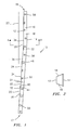
FIG. 1 is a representation of an exemplary expansion device described herein; -
FIG. 2 is a cross-sectional view taken along lines A-A of the exemplary expansion device ofFIG. 1 ; -
FIG. 3 is a flowchart illustrating an exemplary process for applying a coating to an axially split component; -
FIG. 4 is a cross-sectional view of an axially split component; -
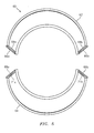
FIG. 5 is a perspective view of an upper half and a lower half of an axially split component; -
FIG. 6 is a cross-sectional view of a pair of expansion devices being disposed between each half of the axially split component and applying a bending moment upon each split flange of each half of the axially split component ofFIG. 4 ; -
FIG. 7 is a perspective view of an assembly composed of the axially split component ofFIG. 4 attached to a pair of the expansion devices of the present disclosure; -
FIG. 8 is a cross-sectional view of the axially split component mounted to the expansion devices; -
FIG. 9 is a cross-sectional view of an axially split component; -
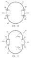
FIG. 10 is a cross-sectional view of a pair of contraction devices being disposed between each half of the axially split component and applying a bending moment upon each split flange of each half of the axially split component ofFIG. 9 ; -
FIG. 11 is a cross-sectional view of the axially split component mounted to the contraction devices; -
FIG. 12 is a stress study of a first run of Table 1; -
FIG. 13 is a stress study of a second run of Table 1; -
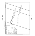
FIG. 14 is a stress study of a third run of Table 1; and -
FIG. 15 is a stress study of a fourth run of Table 1. - Like reference numbers and designations in the various drawings indicate like elements.
- Referring generally to
FIGS. 1-8 , an exemplary expansion device for use in applying coatings to axially split components is now described in detail. Although there are many examples of axially split components to select, the exemplary expansion device will be explained with regard to a split fan casing of a gas turbine engine. - Referring specifically now to
FIGS. 1 and 2 , anexemplary expansion device 10 is shown. Theexpansion device 10 may comprise a wedge-block shaped body (see cross-sectional view ofFIG. 2 ) having aninboard surface 12 and anoutboard surface 14 disposed opposite each other along with afirst engagement surface 16 and asecond engagement surface 18 disposed opposite each other. Therespective surfaces first end 17, asecond end 19 and aconical angle 21 as shown inFIG. 1 . A tapered angle may be formed at a positive angle with respect to theinboard surface 12. - In a split component that has multiple conical angles, the
inboard surface 12 may include a plurality ofintersection points inboard surface 12, for example, a firstconical portion 30, a secondconical portion 32, athird portion 34, afourth portion 36 and afifth portion 38. Each intersection point may also be associated with a change in angle, such that afirst angle 40 may be formed about theinboard surface 12 at thefirst intersection point 20 of the firstconical portion 30 and the secondconical portion 32 using the firstconical portion 30 as a point of reference. Asecond angle 44 may be formed inversely, that is, a negative angle as shown inFIG. 1 , about theinboard surface 12 at asecond intersection point 22 of the secondconical portion 32 and thethird portion 34 using thethird portion 34 as a point of reference. Athird angle 48 may be formed about theinboard surface 12 at athird intersection point 24 of thethird portion 34 and thefourth portion 36 using thethird portion 34 as a point of reference. Afourth angle 52 may be formed inversely about theinboard surface 12 at afourth intersection point 26 of thefourth portion 36 and thefifth portion 38 using thefifth portion 38 as a point of reference. All of these angles are associated with a change in diameter of the split component along the axial length. The angle of the wedge remains constant, while the chord lengths ofsurfaces - Generally, the inboard, first engagement and
second engagement surfaces - The
first engagement surface 16 andsecond engagement surface 18 may include a plurality ofapertures 56 disposed through thefirst engagement surface 16 to thesecond engagement surface 18 for receiving means forattachment 58 such as bolts and other devices, instrument, parts, etc., commonly used to secure two halves of an axially split component together. - The assembly is principally designed to proportionally expand the inner diameter of each half to induce a higher apparent stress to the axially split component, and thus relieving this higher apparent stress upon removal of the expansion devices. The arc length of each half of the axially split component may be expressed according to the following equation:


where the ARC stands for the arc length of a half of the axially split component. - When the expansion devices are applied, the axially split component maintains an inner diameter that is larger, yet proportional to the original inner diameter of the assembled axially split component without the expansion devices. Each half of the axially split component expands to a larger radius while the arc length of each half remains constant. The expansion of each half of the axially split component may be expressed according to the following equation:


- The expansion devices force the axially split component to remain open throughout the thermal spray coating processes. The expansion devices minimize distortion typically experienced due to both the thermal spray bond coat and top coat layers while also promoting adhesion of both coatings to the axially split component by minimizing the stress in both the axially split component and coatings subsequent to releasing the part after the coating processes. The expansion devices are effective in reducing coating residual stresses for 1) tensile stresses on the inner surface of the case; or 2) compressive stresses on the outer surface of the case. The stresses being experience include, for example, (a) shrinkage of at least a portion of each half affected upon solidification of the molten coating materials; (b) shrinkage due to difference between particle temperature (of coating materials) and surface temperature of at least a portion of each half; and (c) the difference in coefficients of thermal expansion between the coating materials and the material of the axially split component; and (d) high velocity particle impact and a peening effect that imparts cold work and residual compressive stress as the coating is deposited.
- When tightening the means for attachment during assembly, the bending motion being applied to the split flanges causes the two halves to maintain the larger proportional inner diameter. Typically, an alternating tightening sequence ensures the split flanges are assembled evenly. The thickness and inward angle of the pitch of the expansion device is directly proportional to the amount of deflection exhibited by the upper half and lower half. The expansion devices maintain a uniform angular expansion with the arc length of the expansion bars being proportional to the diameter of the assembly and original diameter of the axially split component. The inward angle of the pitch is the angle(s) of the engagement surface(s) of the expansion device. The inward angle of the pitch maintains a uniform curvature of the component while the radius of the assembly increases.
- A flowchart illustrating an exemplary process for installing the exemplary expansion device onto an axially split component to create an assembly for applying a coating upon an axially split component is shown in
FIG. 3 . Referring now toFIGS. 4 and5 , anaxially split component 60 may include afirst half 62, e.g., an upper half, having a pair ofaxial split flanges second half 64, e.g., a lower half, having a pair ofaxial split flanges axial split flange apertures FIG. 4 , the axially splitcomponent 60 may possess an original radius (RInitial) at a resting position with theaxial split flanges - In preparation for masking the component, the axially split
component 60 ofFIGS. 4 and5 may undergo a cleaning process as known to one of ordinary skill in the art atstep 70 ofFIG. 3 . After cleaning eachhalf step 72 ofFIG. 3 . Once masked, theupper half 62 andlower half 64 may be assembled to a pair of the aforementionedexemplary expansion devices FIGS. 1 and 2 atstep 74 ofFIG. 3 . - Referring now to
FIGS. 6 and7 , the installation ofexpansion devices split flanges upper half 62 in contact with the engagement surfaces 16 ofexpansion devices apertures apertures 56. Thesplit flanges 71a, 71b oflower half 64 may then be placed in contact with the engagement surfaces 18 ofexpansion devices apertures 71a, 71b with the plurality ofapertures 56. Referring now toFIGS. 7 and8 , once bothhalves expansion device rigid assembly 75. As shown inFIG. 6 , each split flange experiences a bending moment as each flange contacts an engagement surface of each expansion block. Each half of the axially split component then expands to achieve a larger radius (RFinal) (SeeFIG. 8 ) while maintaining a constant curvature. - After assembling the axially split component with the expansion devices, the
assembly 75 may be cleaned in anticipation of being coated as known to one of ordinary skill in the art atstep 76 ofFIG. 3 . Once cleaned, a bond coat material may be applied to at least a portion of theassembly 75 atstep 78 ofFIG. 3 . - The bond coat material may comprise a formula MCrAlY. MCrAlY refers to known metal coating systems in which M denotes nickel, cobalt, iron, platinum or mixtures thereof; Cr denotes chromium; Al denotes aluminum; and Y denotes yttrium. MCrAlY materials are often known as overlay coatings because they are applied in a predetermined composition and do not interact significantly with the substrate during the deposition process. For some non-limiting examples of MCrAlY materials see
U.S. Pat. No. 3,528,861 which describes a FeCrAlY coating as doesU.S. Pat. No. 3,542,530 . In addition,U.S. Pat. No. 3,649,225 describes a composite coating in which a layer of chromium is applied to a substrate prior to the deposition of a MCrAlY coating.U.S. Pat. No. 3,676,085 describes a CoCrAlY overlay coating whileU.S. Pat. No. 3,754,903 describes a NiCoCrAlY overlay coating having particularly high ductility.U.S. Pat. No. 4,078,922 describes a cobalt base structural alloy which derives improved oxidation resistance by virtue of the presence of a combination of hafnium and yttrium. A preferred MCrAlY bond coat composition is described inU.S. Pat. No. Re. 32,121 , which is assigned to the present Assignee and incorporated herein by reference, as having a weight percent compositional range of 5-40 Cr, 8-35 Al, 0.1-2.0 Y, 0.1-7 Si, 0.1-2.0 Hf, balance selected from the group consisting of Ni, Co and mixtures thereof. See alsoU.S. Pat. No. 4,585,481 , which is also assigned to the present Assignee and incorporated herein by reference. - The bond coat material may also comprise Al, PtAl and the like, that are often known in the art as diffusion coatings. In addition, the bond coat material may also comprise Al, PtAl, MCrAlY as described above, and the like, that are often known in the art as cathodic arc coatings.
- These bond coat materials may be applied by any method capable of producing a dense, uniform, adherent coating of the desired composition, such as, but not limited to, an overlay bond coat, diffusion bond coat, cathodic arc bond coat, etc. Such techniques may include, but are not limited to, diffusion processes (e.g., inward, outward, etc.), low pressure plasma-spray, air plasma-spray, sputtering, cathodic arc, electron beam physical vapor deposition, high velocity plasma spray techniques (e.g., HVOF, HVAF), combustion processes, wire spray techniques, laser beam cladding, electron beam cladding, etc.
- The particle size for the bond coat may be of any suitable size, and in embodiments may be between about 15 microns (0.015 mm) and about 100 microns (0.100 mm) with a mean particle size of about 45 microns (0.045 mm). The bond coat may be applied to any suitable thickness, and in embodiments may be about 3 mils (0.076mm) to about 12 mils (0.305 mm) thick. In some embodiments, the thickness may be about 6 mils (0.152 mm) to about 7 mils (0.178 mm) thick.
- Once the bond coat is first applied, a thermal spray coating material may then be applied upon at least a portion of the bond coat layer and/or a portion of the
assembly 75 atstep 80 ofFIG. 3 . Suitable thermal spray coating material may include any suitable materials as known to one of ordinary skill in the art such as porous and or filled metallic materials including aluminum, nickel and copper alloys sprayed alone or with fillers such as polymers, organic and inorganic materials that may include Lucite, polyester, polyvinyl alcohol, graphite, hexagonal boron nitride, bentonite, combinations comprising at least one of the foregoing, and the like. For example, an exemplary thermal spray coating material may be an aluminum silicon alloy filled with Lucite as disclosed inU.S. Patent No. 6,352,264 to Dalzell et al. andU.S. Patent No. 6,089,825 to Walden et al. , both assigned to United Technologies Corporation. - Once both coatings have been applied, the means for
attachment 58 may be removed in order to detach eachhalf expansion device step 82. Any one of a number of suitable methods for removing the means forattachment 58 may be utilized as known to one of ordinary skill in the art. - After removing the
expansion devices assembly 75, each resultantcoated half step 84 ofFIG. 3 . Once cleaned, each cleaned, coatedhalf step 86 ofFIG. 3 . Afterwards, the axially splitcomponent 60 may be assembled and machined to its intended specifications atstep 88 ofFIG. 3 . Once machined, the axially splitcomponent 60 may undergo heat treatment atstep 90 to remove fugitive coating constituents, modify the coating structure, or relieve residual coating stresses that may be present. Any number of heat treatment techniques may be utilized as known to one of ordinary skill in the art. - In an alternative embodiment, the expansion device may also be employed as a contraction device as shown in
FIGS. 9-11 .Contraction devices split flanges inboard surface 12. The resultant assembly containing the contraction devices causes each half of the axially split component to possess a smaller radius yet maintain a constant curvature. - The assembly employing the contraction devices is principally designed to proportionally contract the inner diameter of each half to also induce a higher apparent stress to the axially split component, and thus relieve this higher apparent stress upon removal of the contraction devices. The arc length of each half of the axially split component may be expressed according to the following equation:


where the ARC stands for the arc length of a half of the axially split component. - When the contraction devices are applied, the axially split component maintains an inner diameter that is smaller, yet proportional to the original inner diameter of the assembled axially split component without the contraction devices. Each half of the axially split component contracts to a smaller radius while the arc length of each half remains constant. The contraction of each half of the axially split component may be expressed according to the following equation:


- The contraction devices force the axially split component to remain at a tighter curvature throughout the coating processes such as applying tensile stressed coating on the outer diameter or compressively stressed coatings on the inner diameter. The contraction devices minimize distortion typically experienced due to both the thermal spray bond coat and top coat layers while also promoting adhesion of both coatings to the axially split component by minimizing the stress in both the axially split component and coatings subsequent to releasing the axially split component after completing the coating processes. The contraction devices are effective in reducing coating residual stress for 1) compressive stresses on the inner surface of the case or 2) tensile stresses on the outer surface of the case. The stresses being experience include, for example, (a) shrinkage of at least a portion of each half affected upon solidification of the molten coating materials; (b) shrinkage due to difference between particle temperature (of coating materials) and surface temperature of at least a portion of each half; and (c) the difference in coefficients of thermal expansion between the coating materials and the material of the axially split component; and (d) high velocity particle impact and a peening effect imparts cold work and residual compressive stress as the coating is deposited.
- When tightening the means for attachment during assembly, the bending motion being applied to the split flanges causes the two halves to maintain the smaller proportional inner diameter. Typically, an alternating tightening sequence ensures the split flanges are assembled evenly. The thickness and inward angle of the pitch of the contraction device is directly proportional to the amount of inflection exhibited by the upper half and lower half. The contraction devices maintain a uniform angular expansion with the arc length of the expansion bars being proportional to the diameter of the assembly and original diameter of the axially split component. The outward angle of the pitch is the angle(s) of the engagement surface(s) of the contraction device. The outward angle of the pitch maintains a uniform curvature of the component while the radius of the assembly decreases.
- It should be appreciated that respective coatings may be applied to the same component using both expansion and contraction devices.
- A generic fan casing shown in
FIGS. 12-15 was modeled in a constrained open to larger diameter by 1, 2, and 3 inches using a pair of expansion devices (not shown). The constrained fan casing was then simulated to have coating applied in the constrained lager condition and then returned to nominal diameter for stress analysis. The results of the stress analysis are shown below in Table 1. A value for the coating/fan case interface mismatch stress at nominal diameter of near zero is associated with a neutral stress condition and a reduced tendency for spallation.Table 1 Pre-Spray Stretch (inches) Case surface stress while coating Coating/Case Interface mismatch at nominal diameter Coating Surface Tensile Stress No stretch 0.0 3.0 1.0 +1.0 0.8 2.6 -0.3 +2.0 1.6 1.7 -1.6 +3.0 3.5 0.1 -2.8 - A fan case half was simulated while constrained in a nominal position, that is, no diameter expansion. The observed case surface stress was 0 and coating/case interface mismatch was 3.0. The coating surface tensile stress was normalized to 1.0 (See
FIG. 12 ). - A fan case half was simulated while constrained to nominal diameter +1.0 inches. The observed case surface stress was 0.8 and coating/case interface mismatch was 2.6. The coating surface stress was normalized. However, the observed coating surface tensile stress was -0.3 (See
FIG. 13 ). - A fan case half was simulated while constrained to nominal diameter +2.0 inches. The observed case surface stress was 1.6 and coating/case interface mismatch was 1.7. The coating surface stress was normalized. However, the observed coating surface tensile stress was -1.6 (See
FIG. 14 ). - A fan case half was simulated while nominal diameter +3.0 inches. The observed case surface stress was 3.5 and coating/case interface mismatch was 0.1. The coating surface stress was normalized. However, the observed coating surface tensile stress was -2.8 (See
FIG. 15 ). - Based upon these reported results, the use of the expansion devices lowered the stress discontinuity at coating/case interface to near zero at the final condition of +3.0 inches; lowered the tensile stress due to the coating process transitions to compressive stress on the inner surface of the coating; and, indicated that inner surface cracking and delamination would be minimalized.
- The use of the expansion device of the present disclosure permits one of ordinary skill in the art to exceed known coating parameter limitations. A thicker abradable coating may be applied without experiencing typically related higher coating stresses. In the alternative, a more durable abradable coating of standard thickness as known to one of ordinary skill in the art may be applied. The resultant abradable coating of standard thickness is more durable due to the reduced stress state of the coating in its service condition. As a result, the abradable coating of standard thickness can withstand more rigorous environmental conditions during operation.
- One or more embodiments of the present invention have been described. Nevertheless, it will be understood that various modifications may be made without departing from the scope of the invention. Accordingly, other embodiments are within the scope of the following claims.
Claims (15)
- A process for applying a coating to an axially split component (60), comprising:installing at least one expansion device (10) to at least one half (62) of an axially split component (60);expanding said at least one half (62) to increase a radius of curvature of said at least one half (62);applying at least one coating layer to at least a portion of said at least one half (62); andremoving said at least one expansion device (10) from said at least one half (62).
- The process of claim 1, wherein installing comprises attaching said at least one expansion device (10) to at least one split flange (66a) of said at least one half (62) of said axially split component (60) with attachment means (58).
- The process of claim 2, wherein installing comprises the steps of:providing a first expansion device (10a) and a second expansion device (10b);providing said axially split component (60) comprising a fan casing (60) having a lower half (64) and an upper half (62);attaching a first split flange (66a) of said upper half (62) of said fan casing (60) to a first engagement surface (16) of said first expansion device (10a);attaching a second split flange (66b) of said upper half (62) to a first engagement surface (16) of a second expansion device (10b);attaching a first split flange (68a) of said lower half (64) of said fan casing (60) to a second engagement surface (18) of said first expansion device (10a); andattaching a second split flange (68b) of said lower half (64) to a second engagement surface (18) of said second expansion device (10b).
- A process for applying a coating to an axially split component (60), comprising:installing at least one contraction device (100a) to at least one half (62) of an axially split component (60);contracting said at least one half (62) to decrease a radius of curvature of said at least one half (62);applying at least one coating layer to at least a portion of said at least one half (62); andremoving said at least one contraction device (100a) from said at least one half (62).
- The process of claim 4, wherein installing comprises attaching said at least one contraction device (100a) to at least one split flange (66a) of said at least one half (62) of said axially split component (60) with attachment means.
- The process of claim 5, wherein installing comprises the steps of:providing a first contraction device (100a) and a second contraction device (100b);providing said axially split component (60) comprising a fan casing (60) having a lower half (64) and an upper half (62);attaching a first split flange (66a) of said upper half (62) of said fan casing (60) to a first engagement surface of said first contraction device (100b);attaching a second split flange (66b) of said upper half (62) to a first engagement surface of a second contraction device (100b);attaching a first split flange (68a) of said lower half (64) of said fan casing (60) to a second engagement surface of said first contraction device (100a); andattaching a second split flange of said lower half to a second engagement surface of said second contraction device.
- The process of any preceding claim, further comprising the step of cleaning said at least one half prior (62) to applying said at least one coating layer.
- The process of any preceding claim, further comprising the steps of:cleaning at least one half (62) of said axially split component (60); andmasking at least a portion of at least one cleaned half (62) prior to installing said at least one expansion or contraction device (10,100).
- The process of claim 8, further comprising the steps of:cleaning at least one half (62) after applying said at least one coating layer;demasking at least one half (62);machining at least one half (62); andheat treating at least one half (62).
- The process of any preceding claim, wherein said axially split component (60) comprises a fan casing, and said at least one piece comprises an upper half (62) of said fan casing (60) or a lower half (64) of said fan casing (60).
- An expansion device (10) for use in forming an axially split component, comprising:a wedge-block shaped body;a first end (17);a second end (19) disposed opposite said first end (17); anda tapered angle formed at an angle positively with respect to an inboard surface (12) using said first end (17) as a point of reference.
- A contraction device (100) for use in forming an axially split component, comprising:a wedge-block shaped body;a first end (17);a second end (19) disposed opposite said first end (17); anda tapered angle formed at an angle negatively with respect to an inboard surface (12) using said first end (17) as a point of reference.
- The device of claim 11 or 12, wherein said wedge-block shaped body comprises an inboard surface (12) having a plurality of intersection points (20...26), an outboard (14) surface disposed opposite said inboard surface (12), a first engagement surface (16) disposed opposite a second engagement surface (18), said first engagement surface (16) and said second engagement surface (18) having a means for engaging.
- The device of claim 13, wherein said plurality of intersection points (20...26) further comprise:a first intersection point (20) having a first angle (40) formed about said inboard surface at a first intersection of a first conical portion of said inboard surface and a second conical portion of said inboard surface using said first conical portion as a point of reference;a second intersection point (22) having a second angle (44) formed inversely about said inboard surface at a second intersection point of said second conical portion and a third portion of said inboard surface using said third portion as a point of reference;a third intersection point (24) having a third angle (48) formed about said inboard surface at a third intersection point of said third portion and a fourth portion of said inboard surface using said third portion as a point of reference; anda fourth intersection point (26) having a fourth angle (52) formed inversely about said inboard surface at a fourth intersection point of said fourth portion and a fifth portion of said inboard surface using said fifth portion as a point of reference.
- The device of any of claims 11 to 14, further comprising means for attachment including at least one aperture (69,71) disposed through said first engagement surface (16) and said second engagement surface (18), said at least one aperture (69,71) able to receive means for attachment (58).
Applications Claiming Priority (1)
| Application Number | Priority Date | Filing Date | Title |
|---|---|---|---|
| US12/343,537 US8182881B2 (en) | 2008-12-24 | 2008-12-24 | Methods for reducing stress when applying coatings, processes for applying the same and their coated articles |
Publications (3)
| Publication Number | Publication Date |
|---|---|
| EP2204465A2 true EP2204465A2 (en) | 2010-07-07 |
| EP2204465A3 EP2204465A3 (en) | 2010-12-29 |
| EP2204465B1 EP2204465B1 (en) | 2015-06-24 |
Family
ID=41382328
Family Applications (1)
| Application Number | Title | Priority Date | Filing Date |
|---|---|---|---|
| EP09252237.4A Not-in-force EP2204465B1 (en) | 2008-12-24 | 2009-09-21 | Process for reducing stress when applying coatings. |
Country Status (2)
| Country | Link |
|---|---|
| US (1) | US8182881B2 (en) |
| EP (1) | EP2204465B1 (en) |
Families Citing this family (2)
| Publication number | Priority date | Publication date | Assignee | Title |
|---|---|---|---|---|
| CN103623975B (en) * | 2013-11-21 | 2016-01-06 | 中国南方航空工业(集团)有限公司 | Turboshaft engine compressor casing spraying method and Protecting clamping apparatus thereof |
| CN114894834B (en) * | 2022-07-15 | 2022-10-04 | 西安交通大学 | Device and method for measuring force and heat parameters of high-temperature heat-proof structure |
Citations (10)
| Publication number | Priority date | Publication date | Assignee | Title |
|---|---|---|---|---|
| US3528861A (en) | 1968-05-23 | 1970-09-15 | United Aircraft Corp | Method for coating the superalloys |
| US3542530A (en) | 1968-05-23 | 1970-11-24 | United Aircraft Corp | Nickel or cobalt base with a coating containing iron chromium and aluminum |
| US3649225A (en) | 1969-11-17 | 1972-03-14 | United Aircraft Corp | Composite coating for the superalloys |
| US3676085A (en) | 1971-02-18 | 1972-07-11 | United Aircraft Corp | Cobalt base coating for the superalloys |
| US3754903A (en) | 1970-09-15 | 1973-08-28 | United Aircraft Corp | High temperature oxidation resistant coating alloy |
| US4078922A (en) | 1975-12-08 | 1978-03-14 | United Technologies Corporation | Oxidation resistant cobalt base alloy |
| USRE32121E (en) | 1981-08-05 | 1986-04-22 | United Technologies Corporation | Overlay coatings for superalloys |
| US4585481A (en) | 1981-08-05 | 1986-04-29 | United Technologies Corporation | Overlays coating for superalloys |
| US6089825A (en) | 1998-12-18 | 2000-07-18 | United Technologies Corporation | Abradable seal having improved properties and method of producing seal |
| US6352264B1 (en) | 1999-12-17 | 2002-03-05 | United Technologies Corporation | Abradable seal having improved properties |
Family Cites Families (7)
| Publication number | Priority date | Publication date | Assignee | Title |
|---|---|---|---|---|
| GB844276A (en) | 1958-07-24 | 1960-08-10 | B And W Inc | Stop collar for a well pipe |
| US5310512A (en) * | 1990-11-15 | 1994-05-10 | Norton Company | Method for producing synthetic diamond structures |
| DE4100393C2 (en) | 1991-01-09 | 1994-03-24 | Rheinmetall Gmbh | Process for the treatment of steel hybrid printed circuit boards |
| CN2546294Y (en) | 2002-03-16 | 2003-04-23 | 青岛铁路工务机电技术公司 | Improved rail-impacting block |
| JP3502892B1 (en) * | 2002-12-20 | 2004-03-02 | 博信 黒田 | Two steel fastening structure and fastening parts used for the fastening structure |
| CN100528379C (en) | 2003-12-05 | 2009-08-19 | 上海钢铁工艺技术研究所 | Process for hot spraying of rotating parts |
| US20080085371A1 (en) * | 2006-10-05 | 2008-04-10 | General Electric Company | Fixturing methods and apparatus for thermal spray systems and processes |
-
2008
- 2008-12-24 US US12/343,537 patent/US8182881B2/en not_active Expired - Fee Related
-
2009
- 2009-09-21 EP EP09252237.4A patent/EP2204465B1/en not_active Not-in-force
Patent Citations (10)
| Publication number | Priority date | Publication date | Assignee | Title |
|---|---|---|---|---|
| US3528861A (en) | 1968-05-23 | 1970-09-15 | United Aircraft Corp | Method for coating the superalloys |
| US3542530A (en) | 1968-05-23 | 1970-11-24 | United Aircraft Corp | Nickel or cobalt base with a coating containing iron chromium and aluminum |
| US3649225A (en) | 1969-11-17 | 1972-03-14 | United Aircraft Corp | Composite coating for the superalloys |
| US3754903A (en) | 1970-09-15 | 1973-08-28 | United Aircraft Corp | High temperature oxidation resistant coating alloy |
| US3676085A (en) | 1971-02-18 | 1972-07-11 | United Aircraft Corp | Cobalt base coating for the superalloys |
| US4078922A (en) | 1975-12-08 | 1978-03-14 | United Technologies Corporation | Oxidation resistant cobalt base alloy |
| USRE32121E (en) | 1981-08-05 | 1986-04-22 | United Technologies Corporation | Overlay coatings for superalloys |
| US4585481A (en) | 1981-08-05 | 1986-04-29 | United Technologies Corporation | Overlays coating for superalloys |
| US6089825A (en) | 1998-12-18 | 2000-07-18 | United Technologies Corporation | Abradable seal having improved properties and method of producing seal |
| US6352264B1 (en) | 1999-12-17 | 2002-03-05 | United Technologies Corporation | Abradable seal having improved properties |
Also Published As
| Publication number | Publication date |
|---|---|
| EP2204465A3 (en) | 2010-12-29 |
| EP2204465B1 (en) | 2015-06-24 |
| US20100159149A1 (en) | 2010-06-24 |
| US8182881B2 (en) | 2012-05-22 |
Similar Documents
| Publication | Publication Date | Title |
|---|---|---|
| EP2108715A2 (en) | Thermal barrier coating system and coating methods for gas turbine engine shroud | |
| JP3434504B2 (en) | Insulation method for metal substrate | |
| US20090263574A1 (en) | Method of restoring an article | |
| EP1647611A2 (en) | Thermal barrier coating | |
| US20140234096A1 (en) | Turbomachine component with an erosion and corrosion resistant coating system and method for manufacturing such a component | |
| US20110020548A1 (en) | Device and method for the partial coating of components | |
| US20140120308A1 (en) | Reinforced articles and methods of making the same | |
| WO2014143244A1 (en) | Coating system for improved erosion protection of the leading edge of an airfoil | |
| US20090120101A1 (en) | Organic Matrix Composite Components, Systems Using Such Components, and Methods for Manufacturing Such Components | |
| JP2009519398A (en) | Method for coating blades and blades of gas turbines | |
| US20130323069A1 (en) | Turbine Blade for Industrial Gas Turbine and Industrial Gas Turbine | |
| JP7002443B2 (en) | Contour-following protective layer for compressor components of gas turbines | |
| JP2008063657A (en) | How to apply high temperature resistant fretting wear coatings | |
| US5034284A (en) | Thermal fatigue resistant coatings | |
| US6929868B2 (en) | SRZ-susceptible superalloy article having a protective layer thereon | |
| EP2204465B1 (en) | Process for reducing stress when applying coatings. | |
| EP0893653B2 (en) | Protective coatings for turbine combustion components | |
| US8196600B1 (en) | High-temperature jointed assemblies and wear-resistant coating systems therefor | |
| EP0496935B1 (en) | Aluminide processing of articles protected by a thermal barrier coating system | |
| US20090162690A1 (en) | Thermal barrier coating systems | |
| CA2700899A1 (en) | Wear protection coating | |
| US20100129544A1 (en) | Polymer-Based Ceramic Coatings for Protecting Surfaces Against Fluoride Ions During a Cleaning Process | |
| US8211506B2 (en) | Coating methods and apparatus using pre-formed ceramic mask | |
| US20100189555A1 (en) | Method and assembly for gas turbine engine airfoils with protective coating | |
| Tsantrizes et al. | TBCs on free-standing multilayer components |
Legal Events
| Date | Code | Title | Description |
|---|---|---|---|
| PUAI | Public reference made under article 153(3) epc to a published international application that has entered the european phase |
Free format text: ORIGINAL CODE: 0009012 |
|
| AK | Designated contracting states |
Kind code of ref document: A2 Designated state(s): AT BE BG CH CY CZ DE DK EE ES FI FR GB GR HR HU IE IS IT LI LT LU LV MC MK MT NL NO PL PT RO SE SI SK SM TR |
|
| AX | Request for extension of the european patent |
Extension state: AL BA RS |
|
| PUAL | Search report despatched |
Free format text: ORIGINAL CODE: 0009013 |
|
| AK | Designated contracting states |
Kind code of ref document: A3 Designated state(s): AT BE BG CH CY CZ DE DK EE ES FI FR GB GR HR HU IE IS IT LI LT LU LV MC MK MT NL NO PL PT RO SE SI SK SM TR |
|
| AX | Request for extension of the european patent |
Extension state: AL BA RS |
|
| RIC1 | Information provided on ipc code assigned before grant |
Ipc: C23C 4/00 20060101ALI20101119BHEP Ipc: C23C 4/02 20060101AFI20091208BHEP |
|
| 17P | Request for examination filed |
Effective date: 20110629 |
|
| RBV | Designated contracting states (corrected) |
Designated state(s): DE GB |
|
| RBV | Designated contracting states (corrected) |
Designated state(s): AT BE BG CH CY CZ DE DK EE ES FI FR GB GR HR HU IE IS IT LI LT LU LV MC MK MT NL NO PL PT RO SE SI SK SM TR |
|
| 17Q | First examination report despatched |
Effective date: 20141017 |
|
| GRAP | Despatch of communication of intention to grant a patent |
Free format text: ORIGINAL CODE: EPIDOSNIGR1 |
|
| INTG | Intention to grant announced |
Effective date: 20150311 |
|
| GRAS | Grant fee paid |
Free format text: ORIGINAL CODE: EPIDOSNIGR3 |
|
| GRAA | (expected) grant |
Free format text: ORIGINAL CODE: 0009210 |
|
| AK | Designated contracting states |
Kind code of ref document: B1 Designated state(s): AT BE BG CH CY CZ DE DK EE ES FI FR GB GR HR HU IE IS IT LI LT LU LV MC MK MT NL NO PL PT RO SE SI SK SM TR |
|
| REG | Reference to a national code |
Ref country code: GB Ref legal event code: FG4D |
|
| REG | Reference to a national code |
Ref country code: CH Ref legal event code: EP |
|
| REG | Reference to a national code |
Ref country code: AT Ref legal event code: REF Ref document number: 732920 Country of ref document: AT Kind code of ref document: T Effective date: 20150715 |
|
| REG | Reference to a national code |
Ref country code: IE Ref legal event code: FG4D |
|
| REG | Reference to a national code |
Ref country code: DE Ref legal event code: R096 Ref document number: 602009031835 Country of ref document: DE |
|
| PG25 | Lapsed in a contracting state [announced via postgrant information from national office to epo] |
Ref country code: NO Free format text: LAPSE BECAUSE OF FAILURE TO SUBMIT A TRANSLATION OF THE DESCRIPTION OR TO PAY THE FEE WITHIN THE PRESCRIBED TIME-LIMIT Effective date: 20150924 Ref country code: LT Free format text: LAPSE BECAUSE OF FAILURE TO SUBMIT A TRANSLATION OF THE DESCRIPTION OR TO PAY THE FEE WITHIN THE PRESCRIBED TIME-LIMIT Effective date: 20150624 Ref country code: HR Free format text: LAPSE BECAUSE OF FAILURE TO SUBMIT A TRANSLATION OF THE DESCRIPTION OR TO PAY THE FEE WITHIN THE PRESCRIBED TIME-LIMIT Effective date: 20150624 Ref country code: FI Free format text: LAPSE BECAUSE OF FAILURE TO SUBMIT A TRANSLATION OF THE DESCRIPTION OR TO PAY THE FEE WITHIN THE PRESCRIBED TIME-LIMIT Effective date: 20150624 |
|
| REG | Reference to a national code |
Ref country code: AT Ref legal event code: MK05 Ref document number: 732920 Country of ref document: AT Kind code of ref document: T Effective date: 20150624 |
|
| REG | Reference to a national code |
Ref country code: LT Ref legal event code: MG4D |
|
| PG25 | Lapsed in a contracting state [announced via postgrant information from national office to epo] |
Ref country code: GR Free format text: LAPSE BECAUSE OF FAILURE TO SUBMIT A TRANSLATION OF THE DESCRIPTION OR TO PAY THE FEE WITHIN THE PRESCRIBED TIME-LIMIT Effective date: 20150925 Ref country code: LV Free format text: LAPSE BECAUSE OF FAILURE TO SUBMIT A TRANSLATION OF THE DESCRIPTION OR TO PAY THE FEE WITHIN THE PRESCRIBED TIME-LIMIT Effective date: 20150624 |
|
| REG | Reference to a national code |
Ref country code: NL Ref legal event code: MP Effective date: 20150624 |
|
| PG25 | Lapsed in a contracting state [announced via postgrant information from national office to epo] |
Ref country code: EE Free format text: LAPSE BECAUSE OF FAILURE TO SUBMIT A TRANSLATION OF THE DESCRIPTION OR TO PAY THE FEE WITHIN THE PRESCRIBED TIME-LIMIT Effective date: 20150624 |
|
| PG25 | Lapsed in a contracting state [announced via postgrant information from national office to epo] |
Ref country code: ES Free format text: LAPSE BECAUSE OF FAILURE TO SUBMIT A TRANSLATION OF THE DESCRIPTION OR TO PAY THE FEE WITHIN THE PRESCRIBED TIME-LIMIT Effective date: 20150624 Ref country code: AT Free format text: LAPSE BECAUSE OF FAILURE TO SUBMIT A TRANSLATION OF THE DESCRIPTION OR TO PAY THE FEE WITHIN THE PRESCRIBED TIME-LIMIT Effective date: 20150624 Ref country code: SK Free format text: LAPSE BECAUSE OF FAILURE TO SUBMIT A TRANSLATION OF THE DESCRIPTION OR TO PAY THE FEE WITHIN THE PRESCRIBED TIME-LIMIT Effective date: 20150624 Ref country code: PL Free format text: LAPSE BECAUSE OF FAILURE TO SUBMIT A TRANSLATION OF THE DESCRIPTION OR TO PAY THE FEE WITHIN THE PRESCRIBED TIME-LIMIT Effective date: 20150624 Ref country code: PT Free format text: LAPSE BECAUSE OF FAILURE TO SUBMIT A TRANSLATION OF THE DESCRIPTION OR TO PAY THE FEE WITHIN THE PRESCRIBED TIME-LIMIT Effective date: 20151026 Ref country code: RO Free format text: LAPSE BECAUSE OF NON-PAYMENT OF DUE FEES Effective date: 20150624 Ref country code: CZ Free format text: LAPSE BECAUSE OF FAILURE TO SUBMIT A TRANSLATION OF THE DESCRIPTION OR TO PAY THE FEE WITHIN THE PRESCRIBED TIME-LIMIT Effective date: 20150624 Ref country code: IS Free format text: LAPSE BECAUSE OF FAILURE TO SUBMIT A TRANSLATION OF THE DESCRIPTION OR TO PAY THE FEE WITHIN THE PRESCRIBED TIME-LIMIT Effective date: 20151024 |
|
| REG | Reference to a national code |
Ref country code: DE Ref legal event code: R097 Ref document number: 602009031835 Country of ref document: DE |
|
| PG25 | Lapsed in a contracting state [announced via postgrant information from national office to epo] |
Ref country code: IT Free format text: LAPSE BECAUSE OF FAILURE TO SUBMIT A TRANSLATION OF THE DESCRIPTION OR TO PAY THE FEE WITHIN THE PRESCRIBED TIME-LIMIT Effective date: 20150624 Ref country code: MC Free format text: LAPSE BECAUSE OF FAILURE TO SUBMIT A TRANSLATION OF THE DESCRIPTION OR TO PAY THE FEE WITHIN THE PRESCRIBED TIME-LIMIT Effective date: 20150624 Ref country code: LU Free format text: LAPSE BECAUSE OF FAILURE TO SUBMIT A TRANSLATION OF THE DESCRIPTION OR TO PAY THE FEE WITHIN THE PRESCRIBED TIME-LIMIT Effective date: 20150921 Ref country code: DK Free format text: LAPSE BECAUSE OF FAILURE TO SUBMIT A TRANSLATION OF THE DESCRIPTION OR TO PAY THE FEE WITHIN THE PRESCRIBED TIME-LIMIT Effective date: 20150624 |
|
| PLBE | No opposition filed within time limit |
Free format text: ORIGINAL CODE: 0009261 |
|
| REG | Reference to a national code |
Ref country code: CH Ref legal event code: PL |
|
| STAA | Information on the status of an ep patent application or granted ep patent |
Free format text: STATUS: NO OPPOSITION FILED WITHIN TIME LIMIT |
|
| 26N | No opposition filed |
Effective date: 20160329 |
|
| REG | Reference to a national code |
Ref country code: IE Ref legal event code: MM4A |
|
| REG | Reference to a national code |
Ref country code: FR Ref legal event code: ST Effective date: 20160531 |
|
| PG25 | Lapsed in a contracting state [announced via postgrant information from national office to epo] |
Ref country code: CH Free format text: LAPSE BECAUSE OF NON-PAYMENT OF DUE FEES Effective date: 20150930 Ref country code: LI Free format text: LAPSE BECAUSE OF NON-PAYMENT OF DUE FEES Effective date: 20150930 Ref country code: IE Free format text: LAPSE BECAUSE OF NON-PAYMENT OF DUE FEES Effective date: 20150921 |
|
| PG25 | Lapsed in a contracting state [announced via postgrant information from national office to epo] |
Ref country code: FR Free format text: LAPSE BECAUSE OF NON-PAYMENT OF DUE FEES Effective date: 20150930 Ref country code: SI Free format text: LAPSE BECAUSE OF FAILURE TO SUBMIT A TRANSLATION OF THE DESCRIPTION OR TO PAY THE FEE WITHIN THE PRESCRIBED TIME-LIMIT Effective date: 20150624 |
|
| PG25 | Lapsed in a contracting state [announced via postgrant information from national office to epo] |
Ref country code: BE Free format text: LAPSE BECAUSE OF FAILURE TO SUBMIT A TRANSLATION OF THE DESCRIPTION OR TO PAY THE FEE WITHIN THE PRESCRIBED TIME-LIMIT Effective date: 20150624 |
|
| PG25 | Lapsed in a contracting state [announced via postgrant information from national office to epo] |
Ref country code: MT Free format text: LAPSE BECAUSE OF FAILURE TO SUBMIT A TRANSLATION OF THE DESCRIPTION OR TO PAY THE FEE WITHIN THE PRESCRIBED TIME-LIMIT Effective date: 20150624 |
|
| PG25 | Lapsed in a contracting state [announced via postgrant information from national office to epo] |
Ref country code: SM Free format text: LAPSE BECAUSE OF FAILURE TO SUBMIT A TRANSLATION OF THE DESCRIPTION OR TO PAY THE FEE WITHIN THE PRESCRIBED TIME-LIMIT Effective date: 20150624 Ref country code: BG Free format text: LAPSE BECAUSE OF FAILURE TO SUBMIT A TRANSLATION OF THE DESCRIPTION OR TO PAY THE FEE WITHIN THE PRESCRIBED TIME-LIMIT Effective date: 20150624 Ref country code: HU Free format text: LAPSE BECAUSE OF FAILURE TO SUBMIT A TRANSLATION OF THE DESCRIPTION OR TO PAY THE FEE WITHIN THE PRESCRIBED TIME-LIMIT; INVALID AB INITIO Effective date: 20090921 |
|
| PG25 | Lapsed in a contracting state [announced via postgrant information from national office to epo] |
Ref country code: CY Free format text: LAPSE BECAUSE OF FAILURE TO SUBMIT A TRANSLATION OF THE DESCRIPTION OR TO PAY THE FEE WITHIN THE PRESCRIBED TIME-LIMIT Effective date: 20150624 Ref country code: NL Free format text: LAPSE BECAUSE OF FAILURE TO SUBMIT A TRANSLATION OF THE DESCRIPTION OR TO PAY THE FEE WITHIN THE PRESCRIBED TIME-LIMIT Effective date: 20150624 Ref country code: SE Free format text: LAPSE BECAUSE OF FAILURE TO SUBMIT A TRANSLATION OF THE DESCRIPTION OR TO PAY THE FEE WITHIN THE PRESCRIBED TIME-LIMIT Effective date: 20150624 |
|
| REG | Reference to a national code |
Ref country code: DE Ref legal event code: R082 Ref document number: 602009031835 Country of ref document: DE Representative=s name: SCHMITT-NILSON SCHRAUD WAIBEL WOHLFROM PATENTA, DE |
|
| REG | Reference to a national code |
Ref country code: DE Ref legal event code: R082 Ref document number: 602009031835 Country of ref document: DE Representative=s name: SCHMITT-NILSON SCHRAUD WAIBEL WOHLFROM PATENTA, DE Ref country code: DE Ref legal event code: R081 Ref document number: 602009031835 Country of ref document: DE Owner name: UNITED TECHNOLOGIES CORP. (N.D.GES.D. STAATES , US Free format text: FORMER OWNER: UNITED TECHNOLOGIES CORPORATION, HARTFORD, CONN., US |
|
| PG25 | Lapsed in a contracting state [announced via postgrant information from national office to epo] |
Ref country code: TR Free format text: LAPSE BECAUSE OF FAILURE TO SUBMIT A TRANSLATION OF THE DESCRIPTION OR TO PAY THE FEE WITHIN THE PRESCRIBED TIME-LIMIT Effective date: 20150624 |
|
| PG25 | Lapsed in a contracting state [announced via postgrant information from national office to epo] |
Ref country code: MK Free format text: LAPSE BECAUSE OF FAILURE TO SUBMIT A TRANSLATION OF THE DESCRIPTION OR TO PAY THE FEE WITHIN THE PRESCRIBED TIME-LIMIT Effective date: 20150624 |
|
| REG | Reference to a national code |
Ref country code: DE Ref legal event code: R081 Ref document number: 602009031835 Country of ref document: DE Owner name: RAYTHEON TECHNOLOGIES CORPORATION (N.D.GES.D.S, US Free format text: FORMER OWNER: UNITED TECHNOLOGIES CORP. (N.D.GES.D. STAATES DELAWARE), FARMINGTON, CONN., US |
|
| PGFP | Annual fee paid to national office [announced via postgrant information from national office to epo] |
Ref country code: GB Payment date: 20220819 Year of fee payment: 14 Ref country code: DE Payment date: 20220616 Year of fee payment: 14 |
|
| REG | Reference to a national code |
Ref country code: DE Ref legal event code: R119 Ref document number: 602009031835 Country of ref document: DE |
|
| GBPC | Gb: european patent ceased through non-payment of renewal fee |
Effective date: 20230921 |
|
| PG25 | Lapsed in a contracting state [announced via postgrant information from national office to epo] |
Ref country code: GB Free format text: LAPSE BECAUSE OF NON-PAYMENT OF DUE FEES Effective date: 20230921 |
|
| PG25 | Lapsed in a contracting state [announced via postgrant information from national office to epo] |
Ref country code: GB Free format text: LAPSE BECAUSE OF NON-PAYMENT OF DUE FEES Effective date: 20230921 Ref country code: DE Free format text: LAPSE BECAUSE OF NON-PAYMENT OF DUE FEES Effective date: 20240403 |