EP2204310A2 - Steering column assembly comprising a mounting capsule - Google Patents
Steering column assembly comprising a mounting capsule Download PDFInfo
- Publication number
- EP2204310A2 EP2204310A2 EP10000041A EP10000041A EP2204310A2 EP 2204310 A2 EP2204310 A2 EP 2204310A2 EP 10000041 A EP10000041 A EP 10000041A EP 10000041 A EP10000041 A EP 10000041A EP 2204310 A2 EP2204310 A2 EP 2204310A2
- Authority
- EP
- European Patent Office
- Prior art keywords
- capsule
- capsule portion
- steering column
- arm
- groove
- Prior art date
- Legal status (The legal status is an assumption and is not a legal conclusion. Google has not performed a legal analysis and makes no representation as to the accuracy of the status listed.)
- Withdrawn
Links
Images






Classifications
-
- B—PERFORMING OPERATIONS; TRANSPORTING
- B62—LAND VEHICLES FOR TRAVELLING OTHERWISE THAN ON RAILS
- B62D—MOTOR VEHICLES; TRAILERS
- B62D1/00—Steering controls, i.e. means for initiating a change of direction of the vehicle
- B62D1/02—Steering controls, i.e. means for initiating a change of direction of the vehicle vehicle-mounted
- B62D1/16—Steering columns
- B62D1/18—Steering columns yieldable or adjustable, e.g. tiltable
- B62D1/19—Steering columns yieldable or adjustable, e.g. tiltable incorporating energy-absorbing arrangements, e.g. by being yieldable or collapsible
- B62D1/195—Yieldable supports for the steering column
Definitions
- a steering column mounting apparatus for a vehicle comprises an outer jacket defining a longitudinal axis, an inner jacket disposed along the longitudinal axis within the outer jacket and a bracket coupled to one of the jackets.
- a first capsule portion is coupled to the bracket and includes a first central body and first and second arms extending from the first central body in spaced relation from each other, each of the first and second arms having an outer periphery.
- a second capsule portion is coupled to the first capsule portion.
- the second capsule portion defines first and second grooves extending in spaced relation from each other and extending along the longitudinal axis with the first arm disposed in the first groove and the second arm disposed in the second groove.
- FIG. 11 is a perspective illustrating the separation of the second capsule portion from the first capsule portion of the embodiment of FIG. 10 ;
- FIG. 12 is a perspective view of another embodiment of the first capsule portion coupled to the second capsule portion;
- FIG. 13 is a perspective view illustrating the separation of the second capsule portion from the first capsule portion of the embodiment of FIG. 12 ;
- a driver may contact the steering column assembly 20. As a result of the contact, the driver will exert a force on the steering column assembly 20. If the force is in excess of the predetermined impact force necessary to overcome the coefficient of friction resisting separation of the first and second capsule portions 30, 32 and deform and/or shear the restraint device 72, the first and second capsule portions 30, 32 separate from each other. Separation of the steering column mounting capsule 34 into the first and second capsule portions 30, 32 releases the bracket 28 from the mounting device 36 facilitating collapse of the steering column assembly 20 along the longitudinal axis 24. In this way, the mounting capsule 34, the restraint device 72, and the steering column assembly 20 absorb a portion of energy resulting from the contact between the driver and the steering column assembly 20 during the impact event.
Landscapes
- Engineering & Computer Science (AREA)
- Chemical & Material Sciences (AREA)
- Combustion & Propulsion (AREA)
- Transportation (AREA)
- Mechanical Engineering (AREA)
- Steering Controls (AREA)
Abstract
Description
- The subject invention generally relates to a steering column assembly for a vehicle and, more specifically, to a mounting capsule of the steering column assembly.
- It is in the art that a steering column assembly for a vehicle typically includes an outer jacket defining a longitudinal axis, an inner jacket disposed along the longitudinal axis, a bracket coupled to the outer or inner jacket, and a mounting capsule.
Generally, the mounting capsule allows the bracket coupled to the outer or inner jackets to be mounted to the vehicle. The mounting capsule secures the steering column assembly to the vehicle in a stable operating position. - The mounting capsule further serves as a safety device during an impact event, such as a vehicular crash. The driver typically impacts the steering wheel and thus the steering column assembly during the impact event. The driver exerts a force on the steering column assembly along the longitudinal axis. Application of a predetermined impact force on the steering column assembly along the longitudinal axis will typically separate the mounting capsule from the steering column assembly which releases the steering column assembly from the stable operating position, allowing the steering column assembly to collapse along the longitudinal axis. Separation of the mounting capsule and collapse of the steering column assembly absorbs energy from the driver exerting the force on the steering column assembly and prevents serious injury to the driver from impacting the column assembly.
- In an exemplary embodiment, a steering column assembly comprises an outer jacket defining a longitudinal axis, an inner jacket disposed along the longitudinal axis within the outer jacket and a bracket coupled to one of the jackets. A first capsule portion is coupled to the bracket and includes a first central body and first and second arms each having a periphery and being spaced from each other with the first central body disposed therebetween. A second capsule portion is coupled to the first capsule portion. The second capsule portion defines a first groove and a second groove that are spaced from each other and extend along the longitudinal axis with the first arm disposed in the first groove and the second arm disposed in the second groove. The first and second arms each define a first taper extending from the periphery toward the first central body for reducing relative lateral movement of the inner and outer jackets.
- In another exemplary embodiment a steering column assembly for a vehicle comprises an outer jacket defining a longitudinal axis, an inner jacket disposed along the longitudinal axis within the outer jacket and a bracket coupled to one of the jackets. A first capsule portion is coupled to the bracket and including a first central body and first and second arms each having a periphery and being spaced from each other with the first central body disposed between the first and second arms. A second capsule portion is coupled to the first capsule portion. The second capsule portion defines a first groove and a second groove spaced from each other and extending along the longitudinal axis with the first arm disposed in the first groove and the second arm disposed in the second groove. The first central body further comprises a first body end defining a first recess portion and the second central body further comprising a second body end defining a second recess portion facing the first recess portion when the first and second capsule portions are coupled together to define an aperture for receiving a mounting device to couple the bracket to the vehicle.
- In yet another embodiment, a steering column mounting apparatus for a vehicle comprises an outer jacket defining a longitudinal axis, an inner jacket disposed along the longitudinal axis within the outer jacket and a bracket coupled to one of the jackets. A first capsule portion is coupled to the bracket and includes a first central body and first and second arms extending from the first central body in spaced relation from each other, each of the first and second arms having an outer periphery. A second capsule portion is coupled to the first capsule portion. The second capsule portion defines first and second grooves extending in spaced relation from each other and extending along the longitudinal axis with the first arm disposed in the first groove and the second arm disposed in the second groove. A restraint device engages a first receiver defined by the first arm and is configured to operatively restrain the second capsule portion in engagement with the first capsule portion and is disengageable from the first and second capsule portions upon application of a predetermined impact force to the steering column along the longitudinal axis.
- The above features and advantages, and other features and advantages of the present invention are readily apparent from the following detailed description of the best modes for carrying out the invention when taken in connection with the accompanying drawings.
- Other objects, features, advantages and details appear, by way of example only, in the following detailed description of the embodiments, the detailed description referring to the drawings in which:
-
FIG. 1 is a perspective view of a steering column assembly according to the invention; -
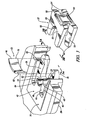
FIG. 2 is a perspective view of a first capsule portion coupled to a second capsule portion biased together by a restraining device comprising a spring; -
FIG. 3 is a partially disassembled view of the first capsule portion, the second capsule portion, and the restraining device comprising the spring ofFIG. 2 ; -
FIG. 3A is a front of the first capsule portion taken atline 3A-3A ofFIG. 3 ; -
FIG. 3B is a front view of the second capsule portion taken atline 3B-3B ofFIG. 3 ; -
FIG. 4 is a top view of the first capsule portion coupled to the second capsule portion biased together by the restraining device comprising the spring; -
FIG. 5 is a partially disassembled perspective view illustrating the second capsule portion disengaged from the first capsule portion; -
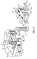
FIG. 6 is a perspective view of another embodiment of the first capsule portion coupled to the second capsule portion and biased together by a restraining device comprising a cam lock and a first shear pin; -
FIG. 7 is a perspective view illustrating the second capsule portion disengaged from the first capsule portion of the embodiment ofFIG. 6 ; -
FIG. 8 is a perspective view of another embodiment of the first capsule portion coupled to the second capsule portion in which the first capsule portion is coupled to the second capsule portion and biased together by a restraining device comprising a shear pin apparatus having a body, a second shear pin, and a third shear pin; -
FIG. 9 is a perspective view illustrating the second capsule portion disengaged from the first capsule of the embodiment ofFIG. 8 ; -
FIG. 10 is a perspective view of another embodiment of the first capsule portion coupled to the second capsule portion; -
FIG. 11 is a perspective illustrating the separation of the second capsule portion from the first capsule portion of the embodiment ofFIG. 10 ; -
FIG. 12 is a perspective view of another embodiment of the first capsule portion coupled to the second capsule portion; -
FIG. 13 is a perspective view illustrating the separation of the second capsule portion from the first capsule portion of the embodiment ofFIG. 12 ; -
FIG. 14 is a perspective view of another embodiment of the first capsule portion coupled to the second capsule portion having an extended second central body; and -
FIG. 15 is a partially disassembled view of the first capsule portion coupled to the second capsule portion comprising the extended second central body ofFIG. 14 . - The following description is merely exemplary in nature and is not intended to limit the present disclosure, application or uses. It should be understood that throughout the drawings, corresponding reference numerals indicate like or corresponding parts and features.
- Referring to the Figures, wherein like numerals indicate like or corresponding parts throughout the several views, a steering column assembly is shown generally at 20 in
FIG. 1 . Thesteering column assembly 20 is intended for use within a vehicle (not shown). Thesteering column assembly 20 generally includes anouter jacket 22 defining alongitudinal axis 24 and aninner jacket 26 disposed along thelongitudinal axis 24 within theouter jacket 22. It should be appreciated that "within" as used in context with the outer andinner jackets outer jacket 22 totally or partially encasing theinner jacket 26, each parallel in orientation and running along thelongitudinal axis 24. Abracket 28 is coupled to the outer orinner jacket first capsule portion 30,FIG.2 , is coupled to the bracket and asecond capsule portion 32 is coupled to the first capsule portion 30 (collectively referred to as "the mounting capsule" 34). - Referring to
FIG. 1 thesteering column assembly 20 embodying the present invention utilizes at least one and preferably twomounting capsules 34 for generally attaching thebracket 28 supporting the outer orinner jacket mounting device 36 that is rigidly fixed to the vehicle. Themounting device 36 is rigidly fixed to the vehicle in a manner which prevents any movement or disengagement of themounting device 36 from the vehicle. - Referring to
FIGS. 2 and3 , thefirst capsule portion 30 is coupled and preferably integrated into thebracket 28 such that thefirst capsule portion 30 and thebracket 28 are manufactured as a single part. Thefirst capsule portion 30 includes afirst arm 38 and asecond arm 40 each having a periphery as best seen inFIG. 3 . A firstcentral body 42 is disposed between and associated with the first andsecond arms second arms central body 42 and extend substantially in parallel to one another and along thelongitudinal axis 24. - The first and
second arms first arm end 44 adjacent the firstcentral body 42 and a seconddistal arm end 46 spaced away from the firstcentral body 42. The firstcentral body 42 includes a first raisedportion 48 extending above the first andsecond arms portion 50 extending below the first andsecond arms FIG. 3B . - Preferably, the
first capsule portion 30 comprises a metal, and preferably steel, however, it should be appreciated that thefirst capsule portion 30 may comprise other suitable materials such as an alloy, plastic, or suitable material known in the art. - Referring to
FIG. 3A the first andsecond arms central body 42. The taper extends in a generally laterally declining angle from thelongitudinal axis 24. The first taper reduces relative lateral movement of the outer andinner jackets steering column assembly 20, in reference to the vehicle, during operation of the vehicle. Preferably the first taper uniformly extends from the peripheries towards the firstcentral body 42; however, it should be appreciated that the first taper can partially extend from the peripheries towards the firstcentral body 42. - The first and
second arms first arm end 44 towards the seconddistal end 46. The second taper reduces relative vertical movement of thesteering column assembly 20, in reference to the vehicle, during operation of the vehicle. Preferably the second taper uniformly extends from thefirst arm end 44 towards the seconddistal arm end 46; however, it should be appreciated that the first taper can partially extend from thefirst arm end 44 towards the seconddistal arm end 46. - Referring to
FIG. 3B thesecond capsule portion 32 comprises a first set offingers 52 and a second set offingers 54. A secondcentral body 56 is disposed between and associated with the first and second set offingers fingers 52 defines afirst groove 58 and the second set offingers 54 define asecond groove 60. The first and second set offingers second groove central body 56 substantially parallel with thelongitudinal axis 24. The first andsecond grooves second arms second arms first capsule portion 30 is coupled to thesecond capsule portion 32 the first andsecond arms second grooves first capsule portion 30 is coupled to thesecond capsule portion 32 the first and second set offingers portions - Preferably, the
second capsule portion 32 comprises a metal, and preferably steel, however, it should be appreciated that thesecond capsule portion 32 can comprise other suitable materials such as an alloy, plastic, or other suitable material known the art. - The first and second tapers are angled, according to the materials used, to form the first and
second capsule portions first capsule portion 30 from separating from thesecond capsule portion 32 after the first andsecond capsule portions - Referring additionally to
FIG. 4 , the firstcentral body 42 comprises afirst body end 62 defining afirst recess 64 and the secondcentral body 56 comprises asecond body end 66 defining asecond recess 68. When the first andsecond capsule portions first recess 64 faces thesecond recess 68 to define anaperture 70 for receiving the mountingdevice 36 to couple thebracket 28 to the vehicle. - Referring to
FIG. 5 arestraint device 72 operatively restrains the first andsecond capsule portions second capsule portions longitudinal axis 24. However, it should be appreciated that therestraint device 72 may restrain or urge the first andsecond capsule portions second capsule portions restraint device 72. Thefirst arm 38 of thefirst capsule portion 30 defines afirst receiver 74 and thesecond arm 40 of thefirst capsule portion 30 defines asecond receiver 76. The first andsecond receivers FIGS. 3 and5 . Therestraint device 72 is mounted to the first andsecond receivers restraint device 72 comprises aspring 78 having afirst restraint end 80 and asecond restraint end 82 opposite the first restraint end. Preferably thespring 78 is a leaf spring that operates to bias thesecond capsule portion 32 into engagement with thefirst capsule portion 30. Thefirst restraint end 80 is mounted to thefirst receiver 74 and therestraint end 82 is mounted to thesecond receiver 76. Thespring 78 engages the second central 56 of thesecond capsule portion 32 for restraining thesecond capsule portion 32 in engagement with thefirst capsule portion 30. Thesecond capsule portion 32 may define a void 84 to facilitate mounting therestraint device 72 to thefirst capsule portion 30. - Preferably, the
spring 78 comprises a resilient material, and preferably spring steel; however, it should be appreciated that thespring 78 may comprise other suitable materials such as an alloy, plastic, or suitable material known in the art. - The
restraint device 72 disengages from the first andsecond receivers second capsule portions steering column assembly 20 during an impact event. - During normal operation, the first and second tapers of the first and
second arms second grooves steering column assembly 20. Thefirst capsule portion 30 will remain engaged with thesecond capsule portion 32 by operation of the frictional forces between the first andsecond arms second grooves fingers portions - During an impact event, a driver may contact the
steering column assembly 20. As a result of the contact, the driver will exert a force on thesteering column assembly 20. If the force is in excess of the predetermined impact force necessary to overcome the coefficient of friction resisting separation of the first andsecond capsule portions restraint device 72, the first andsecond capsule portions column mounting capsule 34 into the first andsecond capsule portions bracket 28 from the mountingdevice 36 facilitating collapse of thesteering column assembly 20 along thelongitudinal axis 24. In this way, the mountingcapsule 34, therestraint device 72, and thesteering column assembly 20 absorb a portion of energy resulting from the contact between the driver and thesteering column assembly 20 during the impact event. - A second embodiment of the mounting
capsule 34 as described above comprises the first andsecond arms second grooves second arms - A third embodiment of the mounting
capsule 34 as described comprises the first andsecond arms central body 42 at an angle away, or declining from thelongitudinal axis 24. - Referring to
FIGS. 6 and7 , a fourth embodiment of the mountingcapsule 34 as described above is illustrated wherein thefirst capsule portion 30 comprises thefirst arm 38 defining thereceiver 74. Therestraint device 72 comprises acam lock 200 and afirst shear pin 202. Thefirst shear pin 202 mounts thecam lock 200 to thesecond receiver 76. Thecam lock 200 engages thesecond capsule portion 32 for restraining thesecond capsule portion 32 in engagement with thefirst capsule portion 30 until released in response to a predetermined impact force. - Referring to
FIGS. 8 and9 , a fifth embodiment of the mountingcapsule 34 as described above is illustrated wherein therestraint device 72 comprises ashear pin apparatus 300 having asecond shear pin 302 and athird shear pin 304 disposed on abody 306. Thesecond shear pin 302 is mounted to thefirst receiver 74 and thethird shear pin 304 is mounted to thesecond receiver 76. Thebody 306 engages thesecond capsule portion 32 for restraining thesecond capsule portion 32 in engagement with thefirst capsule portion 30 until released by severance of theshear pin 302, in response to a predetermined impact force. - Referring to
FIGS. 10 and11 , a sixth embodiment of the mountingcapsule 34 as described above is illustrated wherein thesecond capsule portion 32 comprises the first set offingers 52 and the second set offingers 54 each terminating at acommon end 400. Thecommon end 400 may define first andsecond notches shear pin apparatus 300, respectively. - Referring to
FIGS. 12 and13 , a seventh embodiment of the mountingcapsule 34 as described above is illustrated wherein thesecond capsule portion 32 includes afirst half 100 defining afirst portion 102 of thesecond recess 68 and asecond half 104 defining a second portion 106 of thesecond recess 68, facing thefirst portion 102 when the first and second halves 100,104 are coupled together to define thesecond recess 68. - Referring to
FIGS. 14 and 15 , an eighth embodiment of the mountingcapsule 34 as described above is illustrated wherein the secondcentral body 56 extends the same distance as the first and second set offingers central body 56 defines a front face ornose portion 500 that is received in acorresponding face pocket 501 in the firstcentral body 42. The secondcentral body 56 further defines theaperture 70. - While the forms of the invention herein disclosed constitute presently preferred embodiments, many others are possible. It is not intended herein to mention all the possible equivalent forms or ramifications of the invention. It is understood that terms used herein are merely descriptive, rather than limiting, and that various changes may be made without departing from the spirit or scope of the invention.
Claims (15)
- A steering column assembly comprising:an outer jacket defining a longitudinal axis;an inner jacket disposed along the longitudinal axis within the outer jacket;a bracket coupled to one of the jackets;a first capsule portion coupled to the bracket and including a first central body;a first arm and a second arm each having a periphery and being spaced from each other with the first central body disposed between the first and second arms; anda second capsule portion coupled to the first capsule portion, the second capsule portion defining a first groove and a second groove spaced from each other and extending along the longitudinal axis with the first arm disposed in the first groove and the second arm disposed in the second groove, the first and second arms each defining a first taper extending from the periphery toward the first central body for reducing relative lateral movement of the inner and outer jackets.
- A steering column assembly as set forth in claim 1, wherein the first taper extends from the periphery uniformly to the first central.
- A steering column assembly as set forth in claim 1, wherein the first and second grooves are tapered in a complementary configuration to the first and second arm tapers for receiving the first and second arms therein.
- A steering column assembly as set forth in claim 1, wherein the first and second arms each define a first arm end adjacent the first central body and a second distal end spaced from the first central body with the arms defining a second taper extending from the first end towards the second distal end in combination with the first taper for reducing relative movement of the inner and outer jackets, in particular, wherein the first and second arms define the second taper extending from the first arm end uniformly to the second distal end.
- A steering column assembly as set forth in claim 1, wherein the first and second arms are associated with and extend from the first central body and include a laterally declining angle from the longitudinal axis.
- A steering column assembly as set forth in claim 1, wherein the first central body includes a first wall-portion extending above the first and second arms and a second wall-portion extending below the first and second arms.
- A steering column assembly as set forth in claim 6, wherein the second capsule portion includes a first set of fingers further defining the first groove and a second set of fingers further defining the second groove with the first and second set of fingers abutting the first and second wall portions respectively when the first and second capsule portions are coupled.
- A steering column assembly as set forth in claim 6, wherein the second capsule portion comprises a second central body disposed between the first set of fingers defining the first groove and the second set of fingers defining the second groove opposite the first set of fingers,
in particular, wherein the first central body comprises a first recess portion and the second central body comprises a second recess portion facing the first recess portion when the first and second capsule portions are coupled together to define an aperture for receiving a mounting device to attach the bracket to the vehicle. - A steering column assembly as set forth in claim 1, wherein the second capsule portion comprises a first half defining the first groove and a second half defining the second groove opposite the first groove when the first and second halves are coupled together to define the second capsule portion.
- A steering column assembly for a vehicle comprising:an outer jacket defining a longitudinal axis;an inner jacket disposed along the longitudinal axis within the outer jacketa bracket coupled to one of the jackets;a first capsule portion coupled to the bracket and including a first central body anda first arm and a second arm each having a periphery and being spaced from each other with the first central body disposed between the first and second arms; anda second capsule portion coupled to the first capsule portion, the second capsule portion defining a first groove and a second groove spaced from each other and extending along the longitudinal axis with the first arm disposed in the first groove and the second arm disposed in the second groove, the first central body further comprising a first body end defining a first recess portion and the second central body further comprising a second body end defining a second recess portion facing the first recess portion when the first and second capsule portions are coupled together to define an aperture for receiving a mounting device to couple the bracket to the vehicle.
- A steering column assembly as set forth in claim 10, wherein the aperture has a cylindrical configuration, and/or
wherein the second capsule portion comprises a first half defining a first portion of the second recess portion and a second half defining a second portion of the second recess portion to thereby define the second recess portion when the first and second halves are coupled together. - A steering column mounting apparatus for a vehicle comprising:an outer jacket defining a longitudinal axis;an inner jacket disposed along the longitudinal axis within the outer jacket;a bracket coupled to one of the jackets;a first capsule portion coupled to the bracket and including a first central body, a first arm and a second arm extending from the first central body in spaced relation from each other, each of the first arm and second arm having an outer periphery;a second capsule portion coupled to the first capsule portion, the second capsule portion defining a first groove and a second groove extending in spaced relation from each other and extending along the longitudinal axis with the first arm disposed in the first groove and the second arm disposed in the second groove; anda restraint device engaging a first receiver defined by the first arm and configured to operatively restrain the second capsule portion in engagement with the first capsule portion and disengageable from the first and second capsule portions upon application of a predetermined impact force to the steering column along the longitudinal axis.
- A steering column assembly as set forth in claim 12, wherein the restraint device comprises a cam lock and a first shear pin mounting the cam lock to the first receiver with the cam lock engaging the second capsule portion for restraining the second capsule portion in engagement with the first capsule portion until release of the cam lock in response to severance of the shear pin in response to the predetermined impact force.
- A steering column assembly as set forth in claim 12, wherein the second arm defines a second receiver and the restraint device is coupled to the first and second receivers for restraining the second capsule portion in engagement with the first capsule portion until release of the restraint device in response to the predetermined impact force.
- A steering column assembly as set forth in claim 14, wherein the restraint device comprises a spring member having a first restraint end and a second restraint end with the first restraint end mounted to the first receiver and the second restraint end mounted to the second receiver to bias the spring against the second capsule portion for restraining the second capsule portion in engagement with the first capsule portion until release in response to the predetermined impact force, and/or
wherein the restraint device comprises a shear pin apparatus having a second shear pin and a third pin disposed on a body with the second shear pin mounted to the first receiver and the third shear mounted to the second receiver with the body adjacent to and engaging the second capsule portion for restraining the second capsule portion in engagement with the first capsule portion until release in response to the predetermined impact force.
Applications Claiming Priority (1)
| Application Number | Priority Date | Filing Date | Title |
|---|---|---|---|
| US14240509P | 2009-01-05 | 2009-01-05 |
Publications (2)
| Publication Number | Publication Date |
|---|---|
| EP2204310A2 true EP2204310A2 (en) | 2010-07-07 |
| EP2204310A3 EP2204310A3 (en) | 2011-08-03 |
Family
ID=41611081
Family Applications (1)
| Application Number | Title | Priority Date | Filing Date |
|---|---|---|---|
| EP10000041A Withdrawn EP2204310A3 (en) | 2009-01-05 | 2010-01-05 | Steering column assembly comprising a mounting capsule |
Country Status (2)
| Country | Link |
|---|---|
| US (1) | US8430428B2 (en) |
| EP (1) | EP2204310A3 (en) |
Cited By (1)
| Publication number | Priority date | Publication date | Assignee | Title |
|---|---|---|---|---|
| CN104108416A (en) * | 2013-04-18 | 2014-10-22 | 现代自动车株式会社 | car steering system |
Families Citing this family (9)
| Publication number | Priority date | Publication date | Assignee | Title |
|---|---|---|---|---|
| DE102008062706B3 (en) * | 2008-12-18 | 2010-01-14 | Thyssenkrupp Presta Ag | Steering column for a motor vehicle |
| US8430428B2 (en) * | 2009-01-05 | 2013-04-30 | Steering Solutions Ip Holding Corporation | Steering column assembly comprising a mounting capsule |
| CN102292245B (en) * | 2010-04-12 | 2013-08-14 | 日本精工株式会社 | Steering device |
| US8973944B2 (en) * | 2012-05-31 | 2015-03-10 | Steering Solutions Ip Holding Corporation | System and method for attaching a steering column to a vehicle structure |
| KR101526748B1 (en) * | 2013-12-18 | 2015-06-05 | 현대자동차주식회사 | Charging apparatus braket reducing impact load |
| GB201705272D0 (en) * | 2016-07-07 | 2017-05-17 | Trw Steering Systems Poland Sp Z O O | A steering column assembly |
| US10526003B2 (en) * | 2017-09-28 | 2020-01-07 | Steering Solutions Ip Holding Corporation | Shroud guidance mechanism for steering column |
| US10464592B2 (en) | 2017-10-30 | 2019-11-05 | Steering Solutions Ip Holding Corporation | Steering column motion control assembly |
| JP7079147B2 (en) * | 2018-05-23 | 2022-06-01 | 株式会社ジェイテクト | Steering column |
Family Cites Families (24)
| Publication number | Priority date | Publication date | Assignee | Title |
|---|---|---|---|---|
| US3392599A (en) * | 1966-12-30 | 1968-07-16 | Gen Motors Corp | Energy absorbing device |
| US3868864A (en) * | 1973-09-17 | 1975-03-04 | Gen Motors Corp | Steering column mounting pad |
| US4452096A (en) * | 1981-08-20 | 1984-06-05 | General Motors Corporation | Energy absorbing steering column and capsule mounting therefore |
| JP2556510B2 (en) * | 1987-04-30 | 1996-11-20 | 富士機工株式会社 | Steering column mounting structure |
| ES2033984T3 (en) * | 1987-06-19 | 1993-04-01 | Dr.Ing.H.C. F. Porsche Aktiengesellschaft | FIXING A STEERING COLUMN FOR A CAR WITH A DEFORMING ELEMENT. |
| US5390955A (en) * | 1993-12-23 | 1995-02-21 | Chrysler Corporation | Steering column release capsules |
| JPH08150943A (en) * | 1994-11-30 | 1996-06-11 | Fuji Kiko Co Ltd | Tilt steering column |
| US5673938A (en) * | 1996-05-13 | 1997-10-07 | Chrysler Corporation | Steering column quick-release mounting |
| DE19624218A1 (en) * | 1996-06-18 | 1998-01-02 | Opel Adam Ag | Steering system |
| US5899116A (en) * | 1997-12-08 | 1999-05-04 | General Motors Corporation | Connection for energy-absorbing steering column |
| US5979860A (en) * | 1998-04-16 | 1999-11-09 | Chrysler Corporation | Steering column support apparatus with shearable ribs |
| WO1999061298A1 (en) * | 1998-05-22 | 1999-12-02 | Krupp Presta Ag | Steering column crash system |
| US6062100A (en) * | 1998-12-17 | 2000-05-16 | General Motors Corporation | Connection for energy absorbing steering column |
| JP3468711B2 (en) * | 1999-02-18 | 2003-11-17 | 株式会社山田製作所 | Steering column shock absorber |
| US6176151B1 (en) * | 1999-05-06 | 2001-01-23 | Delphi Technologies, Inc. | Connection for energy absorbing steering column |
| US6419269B1 (en) * | 1999-09-20 | 2002-07-16 | Delphi Technologies | Locking system for adjustable position steering column |
| US6659504B2 (en) * | 2001-05-18 | 2003-12-09 | Delphi Technologies, Inc. | Steering column for a vehicle |
| US6851712B2 (en) * | 2003-04-02 | 2005-02-08 | Mando Corporation | Steering tilt column assembly for vehicle |
| US7178833B2 (en) * | 2004-03-15 | 2007-02-20 | Delphi Technologies, Inc. | Steering column assembly with vertical capsules |
| JP4952875B2 (en) * | 2004-06-04 | 2012-06-13 | 日本精工株式会社 | Steering column device |
| JP4356559B2 (en) * | 2004-08-25 | 2009-11-04 | トヨタ自動車株式会社 | Fastening structure for steering column fixing support |
| US7228755B2 (en) * | 2005-03-31 | 2007-06-12 | Delphi Technologies, Inc. | Release capsule for steering column |
| US20090090210A1 (en) * | 2007-10-05 | 2009-04-09 | Delphi Technologies, Inc. | Collapsible steering column assembly |
| US8430428B2 (en) * | 2009-01-05 | 2013-04-30 | Steering Solutions Ip Holding Corporation | Steering column assembly comprising a mounting capsule |
-
2009
- 2009-12-31 US US12/650,661 patent/US8430428B2/en active Active
-
2010
- 2010-01-05 EP EP10000041A patent/EP2204310A3/en not_active Withdrawn
Non-Patent Citations (1)
| Title |
|---|
| None |
Cited By (2)
| Publication number | Priority date | Publication date | Assignee | Title |
|---|---|---|---|---|
| CN104108416A (en) * | 2013-04-18 | 2014-10-22 | 现代自动车株式会社 | car steering system |
| CN104108416B (en) * | 2013-04-18 | 2018-05-04 | 现代自动车株式会社 | car steering system |
Also Published As
| Publication number | Publication date |
|---|---|
| US8430428B2 (en) | 2013-04-30 |
| EP2204310A3 (en) | 2011-08-03 |
| US20110006509A1 (en) | 2011-01-13 |
Similar Documents
| Publication | Publication Date | Title |
|---|---|---|
| US8430428B2 (en) | Steering column assembly comprising a mounting capsule | |
| CN104943732B (en) | Transfer | |
| US7827880B2 (en) | Steering column assembly with a quick release bolt | |
| CN104203660B (en) | Pedestrian protection for motor vehicles | |
| EP2409882B1 (en) | Seatbelt device | |
| US9421995B2 (en) | Steering device | |
| CN105764772A (en) | Folding Steering Column Assembly | |
| US7798526B2 (en) | Steering column assembly | |
| EP1083109A2 (en) | Shock-absorbing steering assembly | |
| US20060273568A1 (en) | Adaptive energy absorber for steering column | |
| EP3197746B1 (en) | Improved energy absorption module for vehicle steering column assembly | |
| US7661711B2 (en) | Steering column assembly with active energy absorption device | |
| US5769455A (en) | Device for active retraction, in the event of impact, of an automobile vehicle steering column | |
| WO2003095287A1 (en) | Impact absorbing steering column device | |
| US7510213B2 (en) | Adaptive energy absorber for steering column | |
| CN101734217B (en) | Side impact arm rest retracting mechanism | |
| KR100821278B1 (en) | Head fasteners for car headrests | |
| US4862761A (en) | Automobile steering assembly with a telescopic steering column and a pull-away device for the upper steering column part | |
| US20050248141A1 (en) | Adaptive energy absorbing system using pin pullers | |
| US7124866B2 (en) | Adaptive energy absorber | |
| US7441808B2 (en) | Steering column assembly comprising a steering column the tilt and length of which can be modified | |
| KR20140065844A (en) | Steering column device of vehicles | |
| JPH0948353A (en) | Retractable steering column | |
| KR101593524B1 (en) | Impact absorbing seat frame | |
| US10202140B2 (en) | Pin assembly and steering device |
Legal Events
| Date | Code | Title | Description |
|---|---|---|---|
| PUAI | Public reference made under article 153(3) epc to a published international application that has entered the european phase |
Free format text: ORIGINAL CODE: 0009012 |
|
| AK | Designated contracting states |
Kind code of ref document: A2 Designated state(s): AT BE BG CH CY CZ DE DK EE ES FI FR GB GR HR HU IE IS IT LI LT LU LV MC MK MT NL NO PL PT RO SE SI SK SM TR |
|
| AX | Request for extension of the european patent |
Extension state: AL BA RS |
|
| PUAL | Search report despatched |
Free format text: ORIGINAL CODE: 0009013 |
|
| RAP1 | Party data changed (applicant data changed or rights of an application transferred) |
Owner name: GM GLOBAL TECHNOLOGY OPERATIONS LLC |
|
| AK | Designated contracting states |
Kind code of ref document: A3 Designated state(s): AT BE BG CH CY CZ DE DK EE ES FI FR GB GR HR HU IE IS IT LI LT LU LV MC MK MT NL NO PL PT RO SE SI SK SM TR |
|
| AX | Request for extension of the european patent |
Extension state: AL BA RS |
|
| RIC1 | Information provided on ipc code assigned before grant |
Ipc: B62D 1/19 20060101AFI20110627BHEP |
|
| 17P | Request for examination filed |
Effective date: 20120203 |
|
| RAP1 | Party data changed (applicant data changed or rights of an application transferred) |
Owner name: GM GLOBAL TECHNOLOGY OPERATIONS LLC Owner name: STEERING SOLUTIONS IP HOLDING CORPORATION |
|
| STAA | Information on the status of an ep patent application or granted ep patent |
Free format text: STATUS: THE APPLICATION IS DEEMED TO BE WITHDRAWN |
|
| 18D | Application deemed to be withdrawn |
Effective date: 20140801 |