EP2204274A1 - Method of joining sheet member and sheet joined body - Google Patents
Method of joining sheet member and sheet joined body Download PDFInfo
- Publication number
- EP2204274A1 EP2204274A1 EP20090016044 EP09016044A EP2204274A1 EP 2204274 A1 EP2204274 A1 EP 2204274A1 EP 20090016044 EP20090016044 EP 20090016044 EP 09016044 A EP09016044 A EP 09016044A EP 2204274 A1 EP2204274 A1 EP 2204274A1
- Authority
- EP
- European Patent Office
- Prior art keywords
- sheet
- sheet members
- sheet member
- joining
- members
- Prior art date
- Legal status (The legal status is an assumption and is not a legal conclusion. Google has not performed a legal analysis and makes no representation as to the accuracy of the status listed.)
- Granted
Links
- 238000000034 method Methods 0.000 title claims abstract description 31
- 238000010438 heat treatment Methods 0.000 claims abstract description 17
- 239000000463 material Substances 0.000 claims description 54
- 229920005992 thermoplastic resin Polymers 0.000 claims description 14
- 239000006096 absorbing agent Substances 0.000 claims description 12
- 229920005989 resin Polymers 0.000 claims description 12
- 239000011347 resin Substances 0.000 claims description 12
- 229920001187 thermosetting polymer Polymers 0.000 claims description 8
- 238000007747 plating Methods 0.000 claims description 2
- 239000010410 layer Substances 0.000 description 15
- 239000011521 glass Substances 0.000 description 9
- 239000002390 adhesive tape Substances 0.000 description 8
- 238000012545 processing Methods 0.000 description 7
- 239000011248 coating agent Substances 0.000 description 6
- 238000000576 coating method Methods 0.000 description 6
- -1 polyethylene Polymers 0.000 description 6
- 229920002284 Cellulose triacetate Polymers 0.000 description 5
- NNLVGZFZQQXQNW-ADJNRHBOSA-N [(2r,3r,4s,5r,6s)-4,5-diacetyloxy-3-[(2s,3r,4s,5r,6r)-3,4,5-triacetyloxy-6-(acetyloxymethyl)oxan-2-yl]oxy-6-[(2r,3r,4s,5r,6s)-4,5,6-triacetyloxy-2-(acetyloxymethyl)oxan-3-yl]oxyoxan-2-yl]methyl acetate Chemical compound O([C@@H]1O[C@@H]([C@H]([C@H](OC(C)=O)[C@H]1OC(C)=O)O[C@H]1[C@@H]([C@@H](OC(C)=O)[C@H](OC(C)=O)[C@@H](COC(C)=O)O1)OC(C)=O)COC(=O)C)[C@@H]1[C@@H](COC(C)=O)O[C@@H](OC(C)=O)[C@H](OC(C)=O)[C@H]1OC(C)=O NNLVGZFZQQXQNW-ADJNRHBOSA-N 0.000 description 5
- 230000002411 adverse Effects 0.000 description 4
- 230000000052 comparative effect Effects 0.000 description 4
- 238000003825 pressing Methods 0.000 description 4
- 239000000758 substrate Substances 0.000 description 4
- 239000004642 Polyimide Substances 0.000 description 3
- 239000000853 adhesive Substances 0.000 description 3
- 230000000694 effects Effects 0.000 description 3
- 230000004927 fusion Effects 0.000 description 3
- 239000007788 liquid Substances 0.000 description 3
- 239000005020 polyethylene terephthalate Substances 0.000 description 3
- 229920000139 polyethylene terephthalate Polymers 0.000 description 3
- 229920001721 polyimide Polymers 0.000 description 3
- 239000004065 semiconductor Substances 0.000 description 3
- 230000001070 adhesive effect Effects 0.000 description 2
- 239000003795 chemical substances by application Substances 0.000 description 2
- 238000001035 drying Methods 0.000 description 2
- 239000000835 fiber Substances 0.000 description 2
- 230000010355 oscillation Effects 0.000 description 2
- 238000012360 testing method Methods 0.000 description 2
- 229930040373 Paraformaldehyde Natural products 0.000 description 1
- 239000004696 Poly ether ether ketone Substances 0.000 description 1
- 239000004952 Polyamide Substances 0.000 description 1
- 239000004962 Polyamide-imide Substances 0.000 description 1
- 239000005062 Polybutadiene Substances 0.000 description 1
- 239000004697 Polyetherimide Substances 0.000 description 1
- 239000004698 Polyethylene Substances 0.000 description 1
- 239000004743 Polypropylene Substances 0.000 description 1
- 239000004793 Polystyrene Substances 0.000 description 1
- 239000004372 Polyvinyl alcohol Substances 0.000 description 1
- 241000872198 Serjania polyphylla Species 0.000 description 1
- 238000010521 absorption reaction Methods 0.000 description 1
- 239000006229 carbon black Substances 0.000 description 1
- 238000005345 coagulation Methods 0.000 description 1
- 238000011109 contamination Methods 0.000 description 1
- 238000007796 conventional method Methods 0.000 description 1
- 238000001816 cooling Methods 0.000 description 1
- 239000000975 dye Substances 0.000 description 1
- 238000012986 modification Methods 0.000 description 1
- 230000004048 modification Effects 0.000 description 1
- JFNLZVQOOSMTJK-KNVOCYPGSA-N norbornene Chemical compound C1[C@@H]2CC[C@H]1C=C2 JFNLZVQOOSMTJK-KNVOCYPGSA-N 0.000 description 1
- 230000035515 penetration Effects 0.000 description 1
- 239000000049 pigment Substances 0.000 description 1
- 229920003229 poly(methyl methacrylate) Polymers 0.000 description 1
- 229920002647 polyamide Polymers 0.000 description 1
- 229920002312 polyamide-imide Polymers 0.000 description 1
- 229920002857 polybutadiene Polymers 0.000 description 1
- 229920000515 polycarbonate Polymers 0.000 description 1
- 239000004417 polycarbonate Substances 0.000 description 1
- 229920002530 polyetherether ketone Polymers 0.000 description 1
- 229920001601 polyetherimide Polymers 0.000 description 1
- 229920000573 polyethylene Polymers 0.000 description 1
- 239000004926 polymethyl methacrylate Substances 0.000 description 1
- 229920000306 polymethylpentene Polymers 0.000 description 1
- 239000011116 polymethylpentene Substances 0.000 description 1
- 229920006324 polyoxymethylene Polymers 0.000 description 1
- 229920001155 polypropylene Polymers 0.000 description 1
- 229920002223 polystyrene Polymers 0.000 description 1
- 229920002635 polyurethane Polymers 0.000 description 1
- 239000004814 polyurethane Substances 0.000 description 1
- 229920002451 polyvinyl alcohol Polymers 0.000 description 1
- 229920000915 polyvinyl chloride Polymers 0.000 description 1
- 239000004800 polyvinyl chloride Substances 0.000 description 1
- 239000002356 single layer Substances 0.000 description 1
- 229920006259 thermoplastic polyimide Polymers 0.000 description 1
- 230000001960 triggered effect Effects 0.000 description 1
Images



Classifications
-
- B—PERFORMING OPERATIONS; TRANSPORTING
- B29—WORKING OF PLASTICS; WORKING OF SUBSTANCES IN A PLASTIC STATE IN GENERAL
- B29C—SHAPING OR JOINING OF PLASTICS; SHAPING OF MATERIAL IN A PLASTIC STATE, NOT OTHERWISE PROVIDED FOR; AFTER-TREATMENT OF THE SHAPED PRODUCTS, e.g. REPAIRING
- B29C65/00—Joining or sealing of preformed parts, e.g. welding of plastics materials; Apparatus therefor
- B29C65/02—Joining or sealing of preformed parts, e.g. welding of plastics materials; Apparatus therefor by heating, with or without pressure
- B29C65/14—Joining or sealing of preformed parts, e.g. welding of plastics materials; Apparatus therefor by heating, with or without pressure using wave energy, i.e. electromagnetic radiation, or particle radiation
- B29C65/1429—Joining or sealing of preformed parts, e.g. welding of plastics materials; Apparatus therefor by heating, with or without pressure using wave energy, i.e. electromagnetic radiation, or particle radiation characterised by the way of heating the interface
- B29C65/1435—Joining or sealing of preformed parts, e.g. welding of plastics materials; Apparatus therefor by heating, with or without pressure using wave energy, i.e. electromagnetic radiation, or particle radiation characterised by the way of heating the interface at least passing through one of the parts to be joined, i.e. transmission welding
-
- B—PERFORMING OPERATIONS; TRANSPORTING
- B29—WORKING OF PLASTICS; WORKING OF SUBSTANCES IN A PLASTIC STATE IN GENERAL
- B29C—SHAPING OR JOINING OF PLASTICS; SHAPING OF MATERIAL IN A PLASTIC STATE, NOT OTHERWISE PROVIDED FOR; AFTER-TREATMENT OF THE SHAPED PRODUCTS, e.g. REPAIRING
- B29C65/00—Joining or sealing of preformed parts, e.g. welding of plastics materials; Apparatus therefor
- B29C65/02—Joining or sealing of preformed parts, e.g. welding of plastics materials; Apparatus therefor by heating, with or without pressure
- B29C65/14—Joining or sealing of preformed parts, e.g. welding of plastics materials; Apparatus therefor by heating, with or without pressure using wave energy, i.e. electromagnetic radiation, or particle radiation
- B29C65/16—Laser beams
- B29C65/1629—Laser beams characterised by the way of heating the interface
-
- B—PERFORMING OPERATIONS; TRANSPORTING
- B29—WORKING OF PLASTICS; WORKING OF SUBSTANCES IN A PLASTIC STATE IN GENERAL
- B29C—SHAPING OR JOINING OF PLASTICS; SHAPING OF MATERIAL IN A PLASTIC STATE, NOT OTHERWISE PROVIDED FOR; AFTER-TREATMENT OF THE SHAPED PRODUCTS, e.g. REPAIRING
- B29C65/00—Joining or sealing of preformed parts, e.g. welding of plastics materials; Apparatus therefor
- B29C65/02—Joining or sealing of preformed parts, e.g. welding of plastics materials; Apparatus therefor by heating, with or without pressure
- B29C65/14—Joining or sealing of preformed parts, e.g. welding of plastics materials; Apparatus therefor by heating, with or without pressure using wave energy, i.e. electromagnetic radiation, or particle radiation
- B29C65/16—Laser beams
- B29C65/1629—Laser beams characterised by the way of heating the interface
- B29C65/1635—Laser beams characterised by the way of heating the interface at least passing through one of the parts to be joined, i.e. laser transmission welding
-
- B—PERFORMING OPERATIONS; TRANSPORTING
- B29—WORKING OF PLASTICS; WORKING OF SUBSTANCES IN A PLASTIC STATE IN GENERAL
- B29C—SHAPING OR JOINING OF PLASTICS; SHAPING OF MATERIAL IN A PLASTIC STATE, NOT OTHERWISE PROVIDED FOR; AFTER-TREATMENT OF THE SHAPED PRODUCTS, e.g. REPAIRING
- B29C65/00—Joining or sealing of preformed parts, e.g. welding of plastics materials; Apparatus therefor
- B29C65/02—Joining or sealing of preformed parts, e.g. welding of plastics materials; Apparatus therefor by heating, with or without pressure
- B29C65/14—Joining or sealing of preformed parts, e.g. welding of plastics materials; Apparatus therefor by heating, with or without pressure using wave energy, i.e. electromagnetic radiation, or particle radiation
- B29C65/16—Laser beams
- B29C65/1677—Laser beams making use of an absorber or impact modifier
- B29C65/1683—Laser beams making use of an absorber or impact modifier coated on the article
-
- B—PERFORMING OPERATIONS; TRANSPORTING
- B29—WORKING OF PLASTICS; WORKING OF SUBSTANCES IN A PLASTIC STATE IN GENERAL
- B29C—SHAPING OR JOINING OF PLASTICS; SHAPING OF MATERIAL IN A PLASTIC STATE, NOT OTHERWISE PROVIDED FOR; AFTER-TREATMENT OF THE SHAPED PRODUCTS, e.g. REPAIRING
- B29C65/00—Joining or sealing of preformed parts, e.g. welding of plastics materials; Apparatus therefor
- B29C65/02—Joining or sealing of preformed parts, e.g. welding of plastics materials; Apparatus therefor by heating, with or without pressure
- B29C65/18—Joining or sealing of preformed parts, e.g. welding of plastics materials; Apparatus therefor by heating, with or without pressure using heated tools
-
- B—PERFORMING OPERATIONS; TRANSPORTING
- B29—WORKING OF PLASTICS; WORKING OF SUBSTANCES IN A PLASTIC STATE IN GENERAL
- B29C—SHAPING OR JOINING OF PLASTICS; SHAPING OF MATERIAL IN A PLASTIC STATE, NOT OTHERWISE PROVIDED FOR; AFTER-TREATMENT OF THE SHAPED PRODUCTS, e.g. REPAIRING
- B29C65/00—Joining or sealing of preformed parts, e.g. welding of plastics materials; Apparatus therefor
- B29C65/02—Joining or sealing of preformed parts, e.g. welding of plastics materials; Apparatus therefor by heating, with or without pressure
- B29C65/18—Joining or sealing of preformed parts, e.g. welding of plastics materials; Apparatus therefor by heating, with or without pressure using heated tools
- B29C65/24—Joining or sealing of preformed parts, e.g. welding of plastics materials; Apparatus therefor by heating, with or without pressure using heated tools characterised by the means for heating the tool
- B29C65/245—Joining or sealing of preformed parts, e.g. welding of plastics materials; Apparatus therefor by heating, with or without pressure using heated tools characterised by the means for heating the tool the heat transfer being achieved contactless, e.g. by radiation
-
- B—PERFORMING OPERATIONS; TRANSPORTING
- B29—WORKING OF PLASTICS; WORKING OF SUBSTANCES IN A PLASTIC STATE IN GENERAL
- B29C—SHAPING OR JOINING OF PLASTICS; SHAPING OF MATERIAL IN A PLASTIC STATE, NOT OTHERWISE PROVIDED FOR; AFTER-TREATMENT OF THE SHAPED PRODUCTS, e.g. REPAIRING
- B29C66/00—General aspects of processes or apparatus for joining preformed parts
- B29C66/004—Preventing sticking together, e.g. of some areas of the parts to be joined
- B29C66/0042—Preventing sticking together, e.g. of some areas of the parts to be joined of the joining tool and the parts to be joined
- B29C66/0044—Preventing sticking together, e.g. of some areas of the parts to be joined of the joining tool and the parts to be joined using a separating sheet, e.g. fixed on the joining tool
-
- B—PERFORMING OPERATIONS; TRANSPORTING
- B29—WORKING OF PLASTICS; WORKING OF SUBSTANCES IN A PLASTIC STATE IN GENERAL
- B29C—SHAPING OR JOINING OF PLASTICS; SHAPING OF MATERIAL IN A PLASTIC STATE, NOT OTHERWISE PROVIDED FOR; AFTER-TREATMENT OF THE SHAPED PRODUCTS, e.g. REPAIRING
- B29C66/00—General aspects of processes or apparatus for joining preformed parts
- B29C66/005—Detaching the article from the joining tool
-
- B—PERFORMING OPERATIONS; TRANSPORTING
- B29—WORKING OF PLASTICS; WORKING OF SUBSTANCES IN A PLASTIC STATE IN GENERAL
- B29C—SHAPING OR JOINING OF PLASTICS; SHAPING OF MATERIAL IN A PLASTIC STATE, NOT OTHERWISE PROVIDED FOR; AFTER-TREATMENT OF THE SHAPED PRODUCTS, e.g. REPAIRING
- B29C66/00—General aspects of processes or apparatus for joining preformed parts
- B29C66/01—General aspects dealing with the joint area or with the area to be joined
- B29C66/05—Particular design of joint configurations
- B29C66/10—Particular design of joint configurations particular design of the joint cross-sections
- B29C66/11—Joint cross-sections comprising a single joint-segment, i.e. one of the parts to be joined comprising a single joint-segment in the joint cross-section
- B29C66/114—Single butt joints
- B29C66/1142—Single butt to butt joints
-
- B—PERFORMING OPERATIONS; TRANSPORTING
- B29—WORKING OF PLASTICS; WORKING OF SUBSTANCES IN A PLASTIC STATE IN GENERAL
- B29C—SHAPING OR JOINING OF PLASTICS; SHAPING OF MATERIAL IN A PLASTIC STATE, NOT OTHERWISE PROVIDED FOR; AFTER-TREATMENT OF THE SHAPED PRODUCTS, e.g. REPAIRING
- B29C66/00—General aspects of processes or apparatus for joining preformed parts
- B29C66/40—General aspects of joining substantially flat articles, e.g. plates, sheets or web-like materials; Making flat seams in tubular or hollow articles; Joining single elements to substantially flat surfaces
- B29C66/41—Joining substantially flat articles ; Making flat seams in tubular or hollow articles
- B29C66/43—Joining a relatively small portion of the surface of said articles
-
- B—PERFORMING OPERATIONS; TRANSPORTING
- B29—WORKING OF PLASTICS; WORKING OF SUBSTANCES IN A PLASTIC STATE IN GENERAL
- B29C—SHAPING OR JOINING OF PLASTICS; SHAPING OF MATERIAL IN A PLASTIC STATE, NOT OTHERWISE PROVIDED FOR; AFTER-TREATMENT OF THE SHAPED PRODUCTS, e.g. REPAIRING
- B29C66/00—General aspects of processes or apparatus for joining preformed parts
- B29C66/80—General aspects of machine operations or constructions and parts thereof
- B29C66/81—General aspects of the pressing elements, i.e. the elements applying pressure on the parts to be joined in the area to be joined, e.g. the welding jaws or clamps
- B29C66/812—General aspects of the pressing elements, i.e. the elements applying pressure on the parts to be joined in the area to be joined, e.g. the welding jaws or clamps characterised by the composition, by the structure, by the intensive physical properties or by the optical properties of the material constituting the pressing elements, e.g. constituting the welding jaws or clamps
- B29C66/8126—General aspects of the pressing elements, i.e. the elements applying pressure on the parts to be joined in the area to be joined, e.g. the welding jaws or clamps characterised by the composition, by the structure, by the intensive physical properties or by the optical properties of the material constituting the pressing elements, e.g. constituting the welding jaws or clamps characterised by the intensive physical properties or by the optical properties of the material constituting the pressing elements, e.g. constituting the welding jaws or clamps
- B29C66/81266—Optical properties, e.g. transparency, reflectivity
- B29C66/81267—Transparent to electromagnetic radiation, e.g. to visible light
-
- B—PERFORMING OPERATIONS; TRANSPORTING
- B29—WORKING OF PLASTICS; WORKING OF SUBSTANCES IN A PLASTIC STATE IN GENERAL
- B29C—SHAPING OR JOINING OF PLASTICS; SHAPING OF MATERIAL IN A PLASTIC STATE, NOT OTHERWISE PROVIDED FOR; AFTER-TREATMENT OF THE SHAPED PRODUCTS, e.g. REPAIRING
- B29C66/00—General aspects of processes or apparatus for joining preformed parts
- B29C66/80—General aspects of machine operations or constructions and parts thereof
- B29C66/83—General aspects of machine operations or constructions and parts thereof characterised by the movement of the joining or pressing tools
- B29C66/832—Reciprocating joining or pressing tools
- B29C66/8322—Joining or pressing tools reciprocating along one axis
-
- B—PERFORMING OPERATIONS; TRANSPORTING
- B29—WORKING OF PLASTICS; WORKING OF SUBSTANCES IN A PLASTIC STATE IN GENERAL
- B29C—SHAPING OR JOINING OF PLASTICS; SHAPING OF MATERIAL IN A PLASTIC STATE, NOT OTHERWISE PROVIDED FOR; AFTER-TREATMENT OF THE SHAPED PRODUCTS, e.g. REPAIRING
- B29C66/00—General aspects of processes or apparatus for joining preformed parts
- B29C66/80—General aspects of machine operations or constructions and parts thereof
- B29C66/84—Specific machine types or machines suitable for specific applications
- B29C66/853—Machines for changing web rolls or filaments, e.g. for joining a replacement web to an expiring web
-
- B—PERFORMING OPERATIONS; TRANSPORTING
- B29—WORKING OF PLASTICS; WORKING OF SUBSTANCES IN A PLASTIC STATE IN GENERAL
- B29C—SHAPING OR JOINING OF PLASTICS; SHAPING OF MATERIAL IN A PLASTIC STATE, NOT OTHERWISE PROVIDED FOR; AFTER-TREATMENT OF THE SHAPED PRODUCTS, e.g. REPAIRING
- B29C2791/00—Shaping characteristics in general
- B29C2791/004—Shaping under special conditions
- B29C2791/009—Using laser
-
- B—PERFORMING OPERATIONS; TRANSPORTING
- B29—WORKING OF PLASTICS; WORKING OF SUBSTANCES IN A PLASTIC STATE IN GENERAL
- B29C—SHAPING OR JOINING OF PLASTICS; SHAPING OF MATERIAL IN A PLASTIC STATE, NOT OTHERWISE PROVIDED FOR; AFTER-TREATMENT OF THE SHAPED PRODUCTS, e.g. REPAIRING
- B29C65/00—Joining or sealing of preformed parts, e.g. welding of plastics materials; Apparatus therefor
- B29C65/02—Joining or sealing of preformed parts, e.g. welding of plastics materials; Apparatus therefor by heating, with or without pressure
- B29C65/14—Joining or sealing of preformed parts, e.g. welding of plastics materials; Apparatus therefor by heating, with or without pressure using wave energy, i.e. electromagnetic radiation, or particle radiation
- B29C65/16—Laser beams
- B29C65/1603—Laser beams characterised by the type of electromagnetic radiation
- B29C65/1612—Infrared [IR] radiation, e.g. by infrared lasers
- B29C65/1616—Near infrared radiation [NIR], e.g. by YAG lasers
-
- B—PERFORMING OPERATIONS; TRANSPORTING
- B29—WORKING OF PLASTICS; WORKING OF SUBSTANCES IN A PLASTIC STATE IN GENERAL
- B29C—SHAPING OR JOINING OF PLASTICS; SHAPING OF MATERIAL IN A PLASTIC STATE, NOT OTHERWISE PROVIDED FOR; AFTER-TREATMENT OF THE SHAPED PRODUCTS, e.g. REPAIRING
- B29C65/00—Joining or sealing of preformed parts, e.g. welding of plastics materials; Apparatus therefor
- B29C65/02—Joining or sealing of preformed parts, e.g. welding of plastics materials; Apparatus therefor by heating, with or without pressure
- B29C65/14—Joining or sealing of preformed parts, e.g. welding of plastics materials; Apparatus therefor by heating, with or without pressure using wave energy, i.e. electromagnetic radiation, or particle radiation
- B29C65/16—Laser beams
- B29C65/1629—Laser beams characterised by the way of heating the interface
- B29C65/1654—Laser beams characterised by the way of heating the interface scanning at least one of the parts to be joined
-
- B—PERFORMING OPERATIONS; TRANSPORTING
- B29—WORKING OF PLASTICS; WORKING OF SUBSTANCES IN A PLASTIC STATE IN GENERAL
- B29C—SHAPING OR JOINING OF PLASTICS; SHAPING OF MATERIAL IN A PLASTIC STATE, NOT OTHERWISE PROVIDED FOR; AFTER-TREATMENT OF THE SHAPED PRODUCTS, e.g. REPAIRING
- B29C65/00—Joining or sealing of preformed parts, e.g. welding of plastics materials; Apparatus therefor
- B29C65/02—Joining or sealing of preformed parts, e.g. welding of plastics materials; Apparatus therefor by heating, with or without pressure
- B29C65/14—Joining or sealing of preformed parts, e.g. welding of plastics materials; Apparatus therefor by heating, with or without pressure using wave energy, i.e. electromagnetic radiation, or particle radiation
- B29C65/16—Laser beams
- B29C65/1629—Laser beams characterised by the way of heating the interface
- B29C65/1664—Laser beams characterised by the way of heating the interface making use of several radiators
-
- B—PERFORMING OPERATIONS; TRANSPORTING
- B29—WORKING OF PLASTICS; WORKING OF SUBSTANCES IN A PLASTIC STATE IN GENERAL
- B29C—SHAPING OR JOINING OF PLASTICS; SHAPING OF MATERIAL IN A PLASTIC STATE, NOT OTHERWISE PROVIDED FOR; AFTER-TREATMENT OF THE SHAPED PRODUCTS, e.g. REPAIRING
- B29C66/00—General aspects of processes or apparatus for joining preformed parts
- B29C66/004—Preventing sticking together, e.g. of some areas of the parts to be joined
- B29C66/0046—Preventing sticking together, e.g. of some areas of the parts to be joined by the use of a lubricant, e.g. fluid, powder
- B29C66/00461—Preventing sticking together, e.g. of some areas of the parts to be joined by the use of a lubricant, e.g. fluid, powder being liquid, e.g. oil based
-
- B—PERFORMING OPERATIONS; TRANSPORTING
- B29—WORKING OF PLASTICS; WORKING OF SUBSTANCES IN A PLASTIC STATE IN GENERAL
- B29C—SHAPING OR JOINING OF PLASTICS; SHAPING OF MATERIAL IN A PLASTIC STATE, NOT OTHERWISE PROVIDED FOR; AFTER-TREATMENT OF THE SHAPED PRODUCTS, e.g. REPAIRING
- B29C66/00—General aspects of processes or apparatus for joining preformed parts
- B29C66/01—General aspects dealing with the joint area or with the area to be joined
- B29C66/05—Particular design of joint configurations
- B29C66/10—Particular design of joint configurations particular design of the joint cross-sections
- B29C66/11—Joint cross-sections comprising a single joint-segment, i.e. one of the parts to be joined comprising a single joint-segment in the joint cross-section
- B29C66/112—Single lapped joints
- B29C66/1122—Single lap to lap joints, i.e. overlap joints
-
- B—PERFORMING OPERATIONS; TRANSPORTING
- B29—WORKING OF PLASTICS; WORKING OF SUBSTANCES IN A PLASTIC STATE IN GENERAL
- B29C—SHAPING OR JOINING OF PLASTICS; SHAPING OF MATERIAL IN A PLASTIC STATE, NOT OTHERWISE PROVIDED FOR; AFTER-TREATMENT OF THE SHAPED PRODUCTS, e.g. REPAIRING
- B29C66/00—General aspects of processes or apparatus for joining preformed parts
- B29C66/70—General aspects of processes or apparatus for joining preformed parts characterised by the composition, physical properties or the structure of the material of the parts to be joined; Joining with non-plastics material
- B29C66/71—General aspects of processes or apparatus for joining preformed parts characterised by the composition, physical properties or the structure of the material of the parts to be joined; Joining with non-plastics material characterised by the composition of the plastics material of the parts to be joined
-
- B—PERFORMING OPERATIONS; TRANSPORTING
- B29—WORKING OF PLASTICS; WORKING OF SUBSTANCES IN A PLASTIC STATE IN GENERAL
- B29C—SHAPING OR JOINING OF PLASTICS; SHAPING OF MATERIAL IN A PLASTIC STATE, NOT OTHERWISE PROVIDED FOR; AFTER-TREATMENT OF THE SHAPED PRODUCTS, e.g. REPAIRING
- B29C66/00—General aspects of processes or apparatus for joining preformed parts
- B29C66/70—General aspects of processes or apparatus for joining preformed parts characterised by the composition, physical properties or the structure of the material of the parts to be joined; Joining with non-plastics material
- B29C66/73—General aspects of processes or apparatus for joining preformed parts characterised by the composition, physical properties or the structure of the material of the parts to be joined; Joining with non-plastics material characterised by the intensive physical properties of the material of the parts to be joined, by the optical properties of the material of the parts to be joined, by the extensive physical properties of the parts to be joined, by the state of the material of the parts to be joined or by the material of the parts to be joined being a thermoplastic or a thermoset
- B29C66/739—General aspects of processes or apparatus for joining preformed parts characterised by the composition, physical properties or the structure of the material of the parts to be joined; Joining with non-plastics material characterised by the intensive physical properties of the material of the parts to be joined, by the optical properties of the material of the parts to be joined, by the extensive physical properties of the parts to be joined, by the state of the material of the parts to be joined or by the material of the parts to be joined being a thermoplastic or a thermoset characterised by the material of the parts to be joined being a thermoplastic or a thermoset
- B29C66/7392—General aspects of processes or apparatus for joining preformed parts characterised by the composition, physical properties or the structure of the material of the parts to be joined; Joining with non-plastics material characterised by the intensive physical properties of the material of the parts to be joined, by the optical properties of the material of the parts to be joined, by the extensive physical properties of the parts to be joined, by the state of the material of the parts to be joined or by the material of the parts to be joined being a thermoplastic or a thermoset characterised by the material of the parts to be joined being a thermoplastic or a thermoset characterised by the material of at least one of the parts being a thermoplastic
- B29C66/73921—General aspects of processes or apparatus for joining preformed parts characterised by the composition, physical properties or the structure of the material of the parts to be joined; Joining with non-plastics material characterised by the intensive physical properties of the material of the parts to be joined, by the optical properties of the material of the parts to be joined, by the extensive physical properties of the parts to be joined, by the state of the material of the parts to be joined or by the material of the parts to be joined being a thermoplastic or a thermoset characterised by the material of the parts to be joined being a thermoplastic or a thermoset characterised by the material of at least one of the parts being a thermoplastic characterised by the materials of both parts being thermoplastics
-
- B—PERFORMING OPERATIONS; TRANSPORTING
- B29—WORKING OF PLASTICS; WORKING OF SUBSTANCES IN A PLASTIC STATE IN GENERAL
- B29C—SHAPING OR JOINING OF PLASTICS; SHAPING OF MATERIAL IN A PLASTIC STATE, NOT OTHERWISE PROVIDED FOR; AFTER-TREATMENT OF THE SHAPED PRODUCTS, e.g. REPAIRING
- B29C66/00—General aspects of processes or apparatus for joining preformed parts
- B29C66/90—Measuring or controlling the joining process
- B29C66/91—Measuring or controlling the joining process by measuring or controlling the temperature, the heat or the thermal flux
- B29C66/914—Measuring or controlling the joining process by measuring or controlling the temperature, the heat or the thermal flux by controlling or regulating the temperature, the heat or the thermal flux
- B29C66/9141—Measuring or controlling the joining process by measuring or controlling the temperature, the heat or the thermal flux by controlling or regulating the temperature, the heat or the thermal flux by controlling or regulating the temperature
- B29C66/91411—Measuring or controlling the joining process by measuring or controlling the temperature, the heat or the thermal flux by controlling or regulating the temperature, the heat or the thermal flux by controlling or regulating the temperature of the parts to be joined, e.g. the joining process taking the temperature of the parts to be joined into account
-
- B—PERFORMING OPERATIONS; TRANSPORTING
- B29—WORKING OF PLASTICS; WORKING OF SUBSTANCES IN A PLASTIC STATE IN GENERAL
- B29C—SHAPING OR JOINING OF PLASTICS; SHAPING OF MATERIAL IN A PLASTIC STATE, NOT OTHERWISE PROVIDED FOR; AFTER-TREATMENT OF THE SHAPED PRODUCTS, e.g. REPAIRING
- B29C66/00—General aspects of processes or apparatus for joining preformed parts
- B29C66/90—Measuring or controlling the joining process
- B29C66/91—Measuring or controlling the joining process by measuring or controlling the temperature, the heat or the thermal flux
- B29C66/914—Measuring or controlling the joining process by measuring or controlling the temperature, the heat or the thermal flux by controlling or regulating the temperature, the heat or the thermal flux
- B29C66/9161—Measuring or controlling the joining process by measuring or controlling the temperature, the heat or the thermal flux by controlling or regulating the temperature, the heat or the thermal flux by controlling or regulating the heat or the thermal flux, i.e. the heat flux
-
- B—PERFORMING OPERATIONS; TRANSPORTING
- B29—WORKING OF PLASTICS; WORKING OF SUBSTANCES IN A PLASTIC STATE IN GENERAL
- B29C—SHAPING OR JOINING OF PLASTICS; SHAPING OF MATERIAL IN A PLASTIC STATE, NOT OTHERWISE PROVIDED FOR; AFTER-TREATMENT OF THE SHAPED PRODUCTS, e.g. REPAIRING
- B29C66/00—General aspects of processes or apparatus for joining preformed parts
- B29C66/90—Measuring or controlling the joining process
- B29C66/91—Measuring or controlling the joining process by measuring or controlling the temperature, the heat or the thermal flux
- B29C66/919—Measuring or controlling the joining process by measuring or controlling the temperature, the heat or the thermal flux characterised by specific temperature, heat or thermal flux values or ranges
-
- B—PERFORMING OPERATIONS; TRANSPORTING
- B29—WORKING OF PLASTICS; WORKING OF SUBSTANCES IN A PLASTIC STATE IN GENERAL
- B29C—SHAPING OR JOINING OF PLASTICS; SHAPING OF MATERIAL IN A PLASTIC STATE, NOT OTHERWISE PROVIDED FOR; AFTER-TREATMENT OF THE SHAPED PRODUCTS, e.g. REPAIRING
- B29C66/00—General aspects of processes or apparatus for joining preformed parts
- B29C66/90—Measuring or controlling the joining process
- B29C66/91—Measuring or controlling the joining process by measuring or controlling the temperature, the heat or the thermal flux
- B29C66/919—Measuring or controlling the joining process by measuring or controlling the temperature, the heat or the thermal flux characterised by specific temperature, heat or thermal flux values or ranges
- B29C66/9192—Measuring or controlling the joining process by measuring or controlling the temperature, the heat or the thermal flux characterised by specific temperature, heat or thermal flux values or ranges in explicit relation to another variable, e.g. temperature diagrams
- B29C66/91921—Measuring or controlling the joining process by measuring or controlling the temperature, the heat or the thermal flux characterised by specific temperature, heat or thermal flux values or ranges in explicit relation to another variable, e.g. temperature diagrams in explicit relation to another temperature, e.g. to the softening temperature or softening point, to the thermal degradation temperature or to the ambient temperature
- B29C66/91931—Measuring or controlling the joining process by measuring or controlling the temperature, the heat or the thermal flux characterised by specific temperature, heat or thermal flux values or ranges in explicit relation to another variable, e.g. temperature diagrams in explicit relation to another temperature, e.g. to the softening temperature or softening point, to the thermal degradation temperature or to the ambient temperature in explicit relation to the fusion temperature or melting point of the material of one of the parts to be joined
-
- B—PERFORMING OPERATIONS; TRANSPORTING
- B29—WORKING OF PLASTICS; WORKING OF SUBSTANCES IN A PLASTIC STATE IN GENERAL
- B29C—SHAPING OR JOINING OF PLASTICS; SHAPING OF MATERIAL IN A PLASTIC STATE, NOT OTHERWISE PROVIDED FOR; AFTER-TREATMENT OF THE SHAPED PRODUCTS, e.g. REPAIRING
- B29C66/00—General aspects of processes or apparatus for joining preformed parts
- B29C66/90—Measuring or controlling the joining process
- B29C66/93—Measuring or controlling the joining process by measuring or controlling the speed
- B29C66/934—Measuring or controlling the joining process by measuring or controlling the speed by controlling or regulating the speed
-
- B—PERFORMING OPERATIONS; TRANSPORTING
- B29—WORKING OF PLASTICS; WORKING OF SUBSTANCES IN A PLASTIC STATE IN GENERAL
- B29C—SHAPING OR JOINING OF PLASTICS; SHAPING OF MATERIAL IN A PLASTIC STATE, NOT OTHERWISE PROVIDED FOR; AFTER-TREATMENT OF THE SHAPED PRODUCTS, e.g. REPAIRING
- B29C66/00—General aspects of processes or apparatus for joining preformed parts
- B29C66/90—Measuring or controlling the joining process
- B29C66/93—Measuring or controlling the joining process by measuring or controlling the speed
- B29C66/939—Measuring or controlling the joining process by measuring or controlling the speed characterised by specific speed values or ranges
-
- Y—GENERAL TAGGING OF NEW TECHNOLOGICAL DEVELOPMENTS; GENERAL TAGGING OF CROSS-SECTIONAL TECHNOLOGIES SPANNING OVER SEVERAL SECTIONS OF THE IPC; TECHNICAL SUBJECTS COVERED BY FORMER USPC CROSS-REFERENCE ART COLLECTIONS [XRACs] AND DIGESTS
- Y10—TECHNICAL SUBJECTS COVERED BY FORMER USPC
- Y10T—TECHNICAL SUBJECTS COVERED BY FORMER US CLASSIFICATION
- Y10T428/00—Stock material or miscellaneous articles
- Y10T428/31504—Composite [nonstructural laminate]
Definitions
- the present invention relates to a method of joining sheet members together and a sheet jointed body, and more particularly to a method of joining sheet members together, in which band-shaped sheet members are jointed together, and a sheet joined body formed by joining band-shaped sheet members together.
- a tail end of a preceding sheet member 101 is held abutting against a leading end of a newly fed sheet member 102, and adhesive tapes 103, 103 are attached to both the sheet members onto both the upper and lower surfaces, covering the abutted portion, thereby joining the two sheet members 101, 102 together.
- a stepped portion is caused at a joined portion due to the adhesive tapes 103.
- a coated film coated in a subsequent coating step may cause liquid stagnation due to the stepped portion, or a conveying roll or a nip roll may contact edges of the adhesive tapes 103 and hence may be contaminated or damaged.
- Another problem lies in that an adhesive agent of the adhesive tapes 103 may be fluidized due to the heat such as in a drying step, and hence the adhesive strength may be deteriorated.
- FIG. 5B there is proposed another method of joining the sheet members 101, 102, in which a newly fed sheet member 102 is overlapped onto a preceding sheet member 101, and they are joined together via an adhesive tape 103 previously disposed at a leading end portion of the newly fed sheet member 102, and then a side rearward to the preceding sheet member 101 is cut.
- a stepped portion of the joined portion is further enlarged and a tail extension 104 is formed at the tail end of the preceding sheet member 101, which causes a problem in that the tail extension 104 flutters when in conveying the sheet members, and there is a problem in that generation of refuses is triggered, in addition to the aforesaid problem due to the stepped portion.
- a method of joining a first sheet member and a second sheet member together which includes bringing an end face of the first sheet member into abutment with an end face of the second sheet member to provide an abutted portion, heating the abutted portion via a heating medium to thermal-fusion-bond the end faces with each other, and peeling off the heating medium from the first and second sheet members after the thermal-fusion bonding.
- the heating medium is preferably an interposing material that includes any one of a thermoplastic resin having a fusing point higher than that of the first and second sheet members and a thermosetting resin having no fusing point, in which the abutted portion is heated and pressurized by heat plating via the interposing material.
- the heating medium is preferably an interposing material that includes any one of a thermoplastic resin having a fusing point higher than that of the first and second sheet members and a thermosetting resin having no fusing point, and contains a light absorbing agent or has a light absorbing agent coated on the surface of the interposing material, in which the abutted portion is heated by laser irradiation via the interposing material.
- a sheet joined body manufactured by any one of the aforesaid sheet member joining methods.
- a preceding first sheet member and a newly fed second sheet member subsequent to the first sheet member are held in a state where they are joined together via only the end faces thereof, and therefore no stepped portion is created on the joined portion, which produces an advantageous effect of omitting problems due to the stepped portion of the joined portion in the respective subsequent steps. Since they are joined together without using a tacky agent or the like, there are provided advantageous effects in that the adhesive power is unlikely to be deteriorated even if the joined portion is heated, and thus the preceding first sheet member and the newly fed second sheet member subsequent thereto are unlikely to be separated from each other.
- the heating medium is an interposing material having the above structure
- FIGS. 1 to 3 show embodiments of a sheet member joining method of the present invention.
- a sheet member joining method of this embodiment is applicable to a case, where a sheet member 1 (hereinafter referred also to a first sheet member) formed into an elongated band shape and made of a thermoplastic resin is fed to a predetermined processing means (not shown), during the feeding of the first sheet, a newly fed sheet member 2 (hereinafter referred also to a second sheet member) made of the same material is joined to the first sheet member 1 at the timing, at which a terminal end of the first sheet member 1 is about to be rolled out, thereby continuing the processing steps by the processing means.
- the first sheet member 1 and the second sheet member 2 are generally made of the same kind of thermoplastic resin, while on the other hand, the sheet members of the present invention are not necessarily limited to the sheet members made of the same kind of material, and as long as materials are capable of being thermal-fusion-bonded with each other, the sheets may be made of different kinds of material. For example, it is possible to use different kinds of thermoplastic resins having compatibility.
- thermoplastic resin examples include polycarbonate, polyvinyl alcohol, polyethylene, polypropylene, polyethylene terephthalate, polyvinyl chloride, thermoplastic polyimide, triacetylcellulose, polymethyl methacrylate, norbornene resin, polyoxymethylene, polyether ether ketone, polyetherimide, polyamideimide, polybutadiene, polyurethane, polystyrene, polymethylpentene, and polyamide.
- the thickness of a sheet member is preferably in the range of 1 ⁇ m to 2 mm, and more preferably in the range of 10 ⁇ m to 200 ⁇ m.
- a sheet member may be of a single layer or plural layers.
- a sheet member of plural layers may be made by, for example, a laminate of a substrate layer and a protection film layer with a tacky agent. In a case where such sheet members of plural layers are joined together, it is possible to temporarily peel off each layer to allow the respective layers to be joined independently of each other, or possible to join the plural layers without peeling.
- the substrate layer and the protection layer can be peeled off after the joining, even when they are joined together while they are kept in plural layers.
- FIGS. 2A-2D are schematic step views, showing the method of joining sheet members together according to the present invention.
- a terminal end portion of the preceding first sheet member 1 and a leading end portion of the newly fed second sheet member 2 are overlapped to each other, and a given position of an overlapped area is cut by a cutting means 31.
- the tail end of the first sheet member 1 and the leading end of the second sheet member 2 have the same end face shapes (a tail end face 1a of the first sheet member 1 and a leading end face 2a of the second sheet member 2), by the above cutting.
- the shape of the cutting line may be of a straight line shape, a wave shape or a serration shape. From the view points of that the joining strength is to be increased by increasing the joining area of the sheet members and a sheet is to be prevented from being broken apart by dispersing the stress applied to the joined surface in the subsequent processing steps, it is preferable to employ a wave shape, a serration shape or the like, or to cut diagonally relative to a width direction of the sheet members.
- the tail end face 1a of the first sheet member 1 and the leading end face 2a of the second sheet member 2, formed in the above manner are brought into abutment with each other, an interposing material 3 is mounted on an abutted portion, and they are heated and pressed on a base plate 33 by pressing a heat plate 32 thereto from above.
- the tail end face 1a and its periphery of the first sheet member 1 and the leading end face 2a and its periphery of the second sheet member 2 are heated, molten, fused to each other, again coagulated and thereby thermal-fusion-bonded via the interposing material 3.
- a heat plate 32 is pulled upward and the interposing material is peeled off, thus completing the joining of the sheet members 1, 2.
- the heat plate 32 No limitation is intended to the heat plate 32, as long as it can heat the joined area of the sheet members 1, 2 to the fusion temperature or higher.
- a heat plate having a rectangular pressing face extending across the entire width of the sheet member can be appropriately used.
- a means for fixing a sheet member on the base plate 33 for example, a means for fixing by suction a sheet member on the surface of the base plate 33 by generating negative pressure, or any other conventional means for fixing a resin film may be employed.
- thermoplastic resin having a fusing point higher than the sheet members as joining targets, or a thermosetting resin having no fusing point can be appropriately used.
- thermoplastic resin having a fusing point higher than the sheet members the thermoplastic resin having a fusing point 30 °C or higher than the fusing point of the thermoplastic resin forming the sheet members is preferable.
- thermosetting resin a thermosetting polyimide is preferably used.
- the interposing material 3 has a thickness of preferably 20-500 ⁇ m and more preferably 25-150 ⁇ m from the view point that heat from the heat plate can be easily transferred to sheet members therethrough.
- the heating via the interposing material 3 can prevent the sheet members 1, 2 from being fusion bonded to the heat plate 32.
- the heating via the interposing material 3 enables a sheet member to be easily peeled off along with an interposing material without fusion bonding to a heat plate.
- a method of joining sheet members of the second embodiment includes, as shown in FIGS. 3A-3D , cutting the first and second sheet members 1, 2 to form end faces 1a, 1b ( FIGS. 3A and 3B ), and then the end faces 1a, 1b are thermal-fusion-bonded to each other by laser irradiation.
- the tail end face 1a of the first sheet member 1 and the leading end face 2a of the second sheet member 2 formed by cutting are brought into abutment with each other, and the abutted portion is held from above and below with interposing materials 4, 4 which produce heat by laser irradiation, and further held between the base plate 33 and the glass plate 34 as fixing means to be fixed in position. Then, laser light R is irradiated from above the glass plate 35 to let the interposing materials 4, 4 produce heat.
- the tail end face 1a and its periphery of the first sheet member 1 and the leading end face 2a and its periphery of the second sheet member 2 are molten, fused to each other, again coagulated and thereby thermal-fusion-bonded with each other in the same manner as the first embodiment. Then, after the thermal-fusion-bonding has been completed, as shown in FIG. 3D , the glass plate 35 is pulled upward and the interposing materials 4, 4 are peeled off, thus completing the joining of the sheet members 1, 2.
- laser light R No limitation is intended to the laser light R, as long as it can thermal-fusion-bond sheet members via the interposing materials 4, 4.
- laser light produced by various oscillation means such as semiconductor laser, Nd-YAG laser and fiber laser can be employed, and for the oscillation method, it is possible to employ so-called CW laser (Continuous Wave Laser), or pulse laser such as femtosecond laser, which continuously irradiate laser light.
- semiconductor laser and fiber laser can be appropriately used from the view point that uniform in-plane beam strength can be easily produced.
- the wavelength of the laser light is preferably in near infrared wavelength range from the view point that it is excellent in penetration capability through many resin materials, facilitates laser light to reach an interface between the sheet members, and facilitates the thermal-fusion-bonding at the interface without causing adverse influences on the front side of the sheet members.
- thermoplastic resin having a fusing point higher than the sheet members, or a thermosetting resin having no fusing point is appropriately usable in the same manner as the interposing material 3 of the first embodiment.
- a material including a light absorbing agent, which is excellent in absorption of laser light is preferably used.
- the light absorbing agent include pigment, dye and carbon black with porphyrin compound used therein.
- the light absorbing agent is preferably used by being coated on the surface of an interposing material, and the surface with the light absorbing agent is preferably used by being held in contact with the sheet members.
- a coating technique for example, a conventional technique, such as inkjet, coater, dispenser, splay or printing may be used.
- the thickness of an interposing material is preferably not less than 10 ⁇ m but not more than 500 ⁇ m, taking into account the handling performance, although the thickness of the interposing material is not limited to a specific thickness.
- the laser light R may be scanned in the longitudinal direction or width direction of sheet members to carry out thermal-fusion-bonding for a required area.
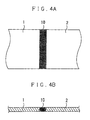
- FIGS. 4A and 4B show an example of a sheet joined body of the present invention, in which FIG. 4A is a plan view and FIG. 4B is a cross sectional view showing the structure of the joined portion.
- the first and second sheet members 1, 2 joined together cause no stepped portion on the joined portion 10, and thus have the same thickness as that of the remaining portion.
- a thus produced sheet joined body has no stepped portion on the joined portion, and therefore it is possible to prevent damages of conveying rollers, nip rollers or other rollers, or various problems in, for example, a coating step, a stretching step, a drying step or the like, and furthermore prevent contamination due to fluttering of a tail extension of a sheet member.
- the joined portion 10 is also made of the same resin material as that of a body portion of each of the sheet members 1, 2, it is possible to carry out the same treatment as that of the remaining portion of each of the sheet members 1, 2 in various subsequent treatment steps.
- the aforesaid embodiments were described by taking, for example, a case where the joined portion 10 is formed to extend continuously across the width direction of the sheet members 1, 2, but, it is not necessary to limit the present invention thereto.
- joined portions of the sheet members may be formed with certain intervals in the width direction to join sheet members together.
- a cooling step may be provided to cool the heated sheet members in order to promote re-coagulation of molten and fused resins.
- the first embodiment which uses the heat plate, was described by taking, for example, a case where the heat plate and the interposing material are disposed only above the sheet members, but the present invention is not necessarily limited to this embodiment.
- the second embodiment which uses the laser irradiation, was described by taking, for example, a case where the interposing materials containing a light absorbing agent are disposed above and below the sheet members, but the present invention is not necessarily limited to this embodiment.
- the second embodiment which uses the aforesaid laser irradiation, was described by taking, for example, a case where the base plate and the glass plate are used as a fixing means for fixing the sheet members in position, but the present invention is not necessarily limited to this embodiment.
- Two sheet members A1 made of TAC (triacetylcellulose) (width: 50 mm, thickness: 80 ⁇ m) were used, whose end portions were overlapped with each other, fixed in position, and cut by a cutter. End faces of the two sheet members formed by cutting were brought into abutment with each other to have an abutted portion, to which an interposing material B1 made of polyimide (manufactured by DU PONT-TORAY CO.,LTD., trade name: Kapton-V, thickness: 25 ⁇ m, 50 mm ⁇ 5 mm) was attached.
- TAC triacetylcellulose
- the two sheet members were placed on a base plate, and pressed with a heat plate via an interposing material B1 to carry out heating and pressing for 10 seconds at 280 °C and 5 kgf/cm 2 . Consequently, the sheet members A1 have been thermal-fusion-bonded with each other, and the interposing material B1 could be easily peeled off from the sheet members A1, and thus the sheet members A1 could be joined together with creating no stepped portion.
- the thus produced sheet joined body was measured in terms of tensile strength, and it was found that the sheet joint body has a high strength of namely 70N/25 mm.
- sheet members A3 made of polyethylene terephthalate (PET) and having a width of 1000 mm and an interposing material B3 made of the same material as that of Example 1 and having a size of 1000 mmx20 mm
- a joining test was carried out in the same manner as Example 1. Consequently, it was found that the sheet members A3 are well joined together across the entire width.
- the joined body was conveyed from a roll to a roll with a tension of 200 N applied thereto, and could be conveyed without rupturing of the sheet members A3. Since no stepped portion exists, it was found that no adverse influences are affected on a nip roll.
- Two sheet members A4 made of TAC (triacetylcellulose) (width: 1000 mm, thickness: 80 ⁇ m) were used, whose end portions were overlapped with each other, fixed in position, and cut by a cutter.
- An interposing material B4 was prepared by coating Clearweld (manufactured by GENTEX Corporation, trade name: LD120C) in a wet condition to a film made of polyimide (manufactured by DU PONT-TORAY CO.,LTD., trade name: Kapton-V, thickness: 125 ⁇ m, 1000 mm ⁇ 5 mm) to have a thickness of 8 ⁇ m.
- Example 2 In the same manner as Example 1, end faces of sheet members A were brought into abutment with each other, and then an adhesive tape (manufactured by Nitto Denko Corporation, trade name: DUNPLON Tape) was attached to the abutted portion from both the front side and the rear side, and thereby the sheet members A were joined together. Consequently, the sheet members A were well joined together, but it was found that a nip roller was scratched due to a stepped portion of the joined portion, and a coating liquid was stagnated on the joined portion.
- an adhesive tape manufactured by Nitto Denko Corporation, trade name: DUNPLON Tape
- An end portion of a sheet member A is overlapped with an end portion of another sheet member A, and an adhesive tape (manufactured by Nitto Denko Corporation, trade name: DUNPLON Tape) was attached only to the front side of the sheet members, and thus the sheet members A were joined together. Consequently, the sheet members A were well joined together, but it was found that a nip roller was scratched due to a stepped portion of the joined portion, and a coating liquid was stagnated on the joined portion. Furthermore, a tail extension formed on the rear side with no adhesive tape attached thereto fluttered during conveyance, and it was found that dusts were generated.
- an adhesive tape manufactured by Nitto Denko Corporation, trade name: DUNPLON Tape
Landscapes
- Engineering & Computer Science (AREA)
- Mechanical Engineering (AREA)
- Physics & Mathematics (AREA)
- Electromagnetism (AREA)
- Optics & Photonics (AREA)
- Health & Medical Sciences (AREA)
- Toxicology (AREA)
- Thermal Sciences (AREA)
- Lining Or Joining Of Plastics Or The Like (AREA)
Abstract
Description
- This application claims priority from Japanese Patent Application No.
2008-330036 - The present invention relates to a method of joining sheet members together and a sheet jointed body, and more particularly to a method of joining sheet members together, in which band-shaped sheet members are jointed together, and a sheet joined body formed by joining band-shaped sheet members together.
- Hitherto, when band-shaped sheet members are to be continuously fed to a processing machine to be processed, a leading end of a newly fed sheet member is joined to a tail end of a preceding sheet member so as to successively feed the newly fed sheet member subsequent to the preceding sheet member to the processing machine.
- Hitherto, as a joining method of this kind, as shown in
FIG. 5A , a tail end of a precedingsheet member 101 is held abutting against a leading end of a newly fedsheet member 102, andadhesive tapes sheet members - In a case where the
sheet members adhesive tapes 103. For example, a coated film coated in a subsequent coating step may cause liquid stagnation due to the stepped portion, or a conveying roll or a nip roll may contact edges of theadhesive tapes 103 and hence may be contaminated or damaged. Another problem lies in that an adhesive agent of theadhesive tapes 103 may be fluidized due to the heat such as in a drying step, and hence the adhesive strength may be deteriorated. - As shown in
FIG. 5B , there is proposed another method of joining thesheet members sheet member 102 is overlapped onto a precedingsheet member 101, and they are joined together via anadhesive tape 103 previously disposed at a leading end portion of the newly fedsheet member 102, and then a side rearward to the precedingsheet member 101 is cut. - However, when the above method is employed, a stepped portion of the joined portion is further enlarged and a
tail extension 104 is formed at the tail end of the precedingsheet member 101, which causes a problem in that thetail extension 104 flutters when in conveying the sheet members, and there is a problem in that generation of refuses is triggered, in addition to the aforesaid problem due to the stepped portion. - In consideration of the above conventional problems, it is an object of the present invention to provide a method of joining sheet members together that is capable of joining two sheet members together without causing a stepped portion on a joined portion. It is another object of the present invention to provide a sheet joined body that has no stepped portion at a joined portion.
- According to the present invention, there is provided a method of joining a first sheet member and a second sheet member together, which includes bringing an end face of the first sheet member into abutment with an end face of the second sheet member to provide an abutted portion, heating the abutted portion via a heating medium to thermal-fusion-bond the end faces with each other, and peeling off the heating medium from the first and second sheet members after the thermal-fusion bonding.
- In the sheet member joining method of the present invention, the heating medium is preferably an interposing material that includes any one of a thermoplastic resin having a fusing point higher than that of the first and second sheet members and a thermosetting resin having no fusing point, in which the abutted portion is heated and pressurized by heat plating via the interposing material.
- In the sheet member joining method of the present invention, the heating medium is preferably an interposing material that includes any one of a thermoplastic resin having a fusing point higher than that of the first and second sheet members and a thermosetting resin having no fusing point, and contains a light absorbing agent or has a light absorbing agent coated on the surface of the interposing material, in which the abutted portion is heated by laser irradiation via the interposing material.
- Furthermore, according to another aspect of the present invention, there is provided a sheet joined body manufactured by any one of the aforesaid sheet member joining methods.
- According to the method of joining sheet members and the sheet joined body of the present invention, a preceding first sheet member and a newly fed second sheet member subsequent to the first sheet member are held in a state where they are joined together via only the end faces thereof, and therefore no stepped portion is created on the joined portion, which produces an advantageous effect of omitting problems due to the stepped portion of the joined portion in the respective subsequent steps.
Since they are joined together without using a tacky agent or the like, there are provided advantageous effects in that the adhesive power is unlikely to be deteriorated even if the joined portion is heated, and thus the preceding first sheet member and the newly fed second sheet member subsequent thereto are unlikely to be separated from each other. - Furthermore, in a case where the heating medium is an interposing material having the above structure, it is possible to intensively heat only the area with which the interposing material is held in contact, and moreover, the interposing material is more securely attached to the boundary portion between the first sheet member and the second sheet member, and therefore the joined portion of the sheet members are brought into a remarkably flat condition.
-
-
FIG. 1 is a perspective view showing the relationship between a precedingfirst sheet member 1 and a newly fedsecond sheet member 2 subsequent thereto, before a joining method of this embodiment is applied. -
FIGS. 2A-2D are schematic step views, showing the method of joining sheet members together according to a first embodiment. -
FIGS. 3A-3D are schematic step views showing the method of joining sheet members together according to a second embodiment. -
FIGS. 4A and 4B show a sheet joined body of one embodiment, in whichFIG. 4A is a plan view andFIG. 4B is a cross sectional view. -
FIGS. 5A and 5B show a joining method of sheet members according to a prior art. - Hereinafter, preferred embodiments according to the present invention will be described with reference to the attached drawings.
-
FIGS. 1 to 3 show embodiments of a sheet member joining method of the present invention. As shown inFIG. 1 , a sheet member joining method of this embodiment is applicable to a case, where a sheet member 1 (hereinafter referred also to a first sheet member) formed into an elongated band shape and made of a thermoplastic resin is fed to a predetermined processing means (not shown), during the feeding of the first sheet, a newly fed sheet member 2 (hereinafter referred also to a second sheet member) made of the same material is joined to thefirst sheet member 1 at the timing, at which a terminal end of thefirst sheet member 1 is about to be rolled out, thereby continuing the processing steps by the processing means. - The
first sheet member 1 and thesecond sheet member 2 are generally made of the same kind of thermoplastic resin, while on the other hand, the sheet members of the present invention are not necessarily limited to the sheet members made of the same kind of material, and as long as materials are capable of being thermal-fusion-bonded with each other, the sheets may be made of different kinds of material. For example, it is possible to use different kinds of thermoplastic resins having compatibility. - Examples of the thermoplastic resin include polycarbonate, polyvinyl alcohol, polyethylene, polypropylene, polyethylene terephthalate, polyvinyl chloride, thermoplastic polyimide, triacetylcellulose, polymethyl methacrylate, norbornene resin, polyoxymethylene, polyether ether ketone, polyetherimide, polyamideimide, polybutadiene, polyurethane, polystyrene, polymethylpentene, and polyamide.
- Since the processing treatment to sheet members is made while being conveyed by a so-called roll-to-roll system, the thickness of a sheet member is preferably in the range of 1 µm to 2 mm, and more preferably in the range of 10 µm to 200 µm.
A sheet member may be of a single layer or plural layers. A sheet member of plural layers may be made by, for example, a laminate of a substrate layer and a protection film layer with a tacky agent.
In a case where such sheet members of plural layers are joined together, it is possible to temporarily peel off each layer to allow the respective layers to be joined independently of each other, or possible to join the plural layers without peeling. In a case where a substrate layer has poor compatibility with a protection film layer and does not form mixed layers even if they are molten, the substrate layer and the protection layer can be peeled off after the joining, even when they are joined together while they are kept in plural layers. -
FIGS. 2A-2D are schematic step views, showing the method of joining sheet members together according to the present invention. In the first embodiment, as shown inFIG. 2A , a terminal end portion of the precedingfirst sheet member 1 and a leading end portion of the newly fedsecond sheet member 2 are overlapped to each other, and a given position of an overlapped area is cut by acutting means 31. - As shown in
FIG. 2B , the tail end of thefirst sheet member 1 and the leading end of thesecond sheet member 2 have the same end face shapes (atail end face 1a of thefirst sheet member 1 and a leadingend face 2a of the second sheet member 2), by the above cutting.
No limitation is intended to the shape of the cutting line, and for example, it may be of a straight line shape, a wave shape or a serration shape. From the view points of that the joining strength is to be increased by increasing the joining area of the sheet members and a sheet is to be prevented from being broken apart by dispersing the stress applied to the joined surface in the subsequent processing steps, it is preferable to employ a wave shape, a serration shape or the like, or to cut diagonally relative to a width direction of the sheet members. - Then, as shown in
FIG. 2C , thetail end face 1a of thefirst sheet member 1 and the leadingend face 2a of thesecond sheet member 2, formed in the above manner are brought into abutment with each other, an interposingmaterial 3 is mounted on an abutted portion, and they are heated and pressed on abase plate 33 by pressing aheat plate 32 thereto from above. Whereby, thetail end face 1a and its periphery of thefirst sheet member 1 and the leadingend face 2a and its periphery of thesecond sheet member 2 are heated, molten, fused to each other, again coagulated and thereby thermal-fusion-bonded via the interposingmaterial 3. Then, after thermal-fusion-bonding has been completed, as shown inFIG. 2D , aheat plate 32 is pulled upward and the interposing material is peeled off, thus completing the joining of thesheet members - No limitation is intended to the
heat plate 32, as long as it can heat the joined area of thesheet members - Furthermore, as a means for fixing a sheet member on the
base plate 33, for example, a means for fixing by suction a sheet member on the surface of thebase plate 33 by generating negative pressure, or any other conventional means for fixing a resin film may be employed. - For the interposing
material 3, a thermoplastic resin having a fusing point higher than the sheet members as joining targets, or a thermosetting resin having no fusing point can be appropriately used. In a case where a thermoplastic resin having a fusing point higher than the sheet members is used, the thermoplastic resin having a fusing point 30 °C or higher than the fusing point of the thermoplastic resin forming the sheet members is preferable. As a thermosetting resin, a thermosetting polyimide is preferably used. - Furthermore, the interposing
material 3 has a thickness of preferably 20-500 µm and more preferably 25-150 µm from the view point that heat from the heat plate can be easily transferred to sheet members therethrough.
The heating via the interposingmaterial 3 can prevent thesheet members heat plate 32.
The heating via the interposingmaterial 3 enables a sheet member to be easily peeled off along with an interposing material without fusion bonding to a heat plate. - Now, the description will be made for a second embodiment of the present invention with reference to
FIGS. 3A-3D . In the second embodiment" the same reference codes are allocated to the same members or parts of the first embodiment to omit the description thereof. - A method of joining sheet members of the second embodiment includes, as shown in
FIGS. 3A-3D , cutting the first andsecond sheet members FIGS. 3A and 3B ), and then the end faces 1a, 1b are thermal-fusion-bonded to each other by laser irradiation. - Specifically, as shown in
FIG. 3C , thetail end face 1a of thefirst sheet member 1 and theleading end face 2a of thesecond sheet member 2 formed by cutting are brought into abutment with each other, and the abutted portion is held from above and below with interposingmaterials base plate 33 and the glass plate 34 as fixing means to be fixed in position. Then, laser light R is irradiated from above theglass plate 35 to let the interposingmaterials tail end face 1a and its periphery of thefirst sheet member 1 and theleading end face 2a and its periphery of thesecond sheet member 2 are molten, fused to each other, again coagulated and thereby thermal-fusion-bonded with each other in the same manner as the first embodiment.
Then, after the thermal-fusion-bonding has been completed, as shown inFIG. 3D , theglass plate 35 is pulled upward and the interposingmaterials sheet members - No limitation is intended to the laser light R, as long as it can thermal-fusion-bond sheet members via the interposing
materials
Moreover, the wavelength of the laser light is preferably in near infrared wavelength range from the view point that it is excellent in penetration capability through many resin materials, facilitates laser light to reach an interface between the sheet members, and facilitates the thermal-fusion-bonding at the interface without causing adverse influences on the front side of the sheet members. - For the interposing
materials 4, a thermoplastic resin having a fusing point higher than the sheet members, or a thermosetting resin having no fusing point is appropriately usable in the same manner as the interposingmaterial 3 of the first embodiment. Furthermore, a material including a light absorbing agent, which is excellent in absorption of laser light is preferably used. Examples of the light absorbing agent include pigment, dye and carbon black with porphyrin compound used therein. The light absorbing agent is preferably used by being coated on the surface of an interposing material, and the surface with the light absorbing agent is preferably used by being held in contact with the sheet members. As a coating technique, for example, a conventional technique, such as inkjet, coater, dispenser, splay or printing may be used.
In a case where laser light is irradiated, since a layer containing a light absorbing agent produces heat, the thickness of an interposing material is preferably not less than 10 µm but not more than 500 µm, taking into account the handling performance, although the thickness of the interposing material is not limited to a specific thickness. - No limitation is intended to the irradiation form of the laser light R, and, for example, a light beam crossing the entire width of an abutted area of sheet members may be irradiated, or plural laser beams disposed with certain intervals in the width direction of sheet members may be irradiated. Alternatively, the laser light R may be scanned in the longitudinal direction or width direction of sheet members to carry out thermal-fusion-bonding for a required area.
-
FIGS. 4A and 4B show an example of a sheet joined body of the present invention, in whichFIG. 4A is a plan view andFIG. 4B is a cross sectional view showing the structure of the joined portion. As shown inFIG. 4B , the first andsecond sheet members portion 10, and thus have the same thickness as that of the remaining portion.
Accordingly, a thus produced sheet joined body has no stepped portion on the joined portion, and therefore it is possible to prevent damages of conveying rollers, nip rollers or other rollers, or various problems in, for example, a coating step, a stretching step, a drying step or the like, and furthermore prevent contamination due to fluttering of a tail extension of a sheet member.
Furthermore, since the joinedportion 10 is also made of the same resin material as that of a body portion of each of thesheet members sheet members - In the present invention, it is a matter of course to appropriately employ conventional technical matters to such an extent as not to significantly deteriorate advantageous effects of the present invention.
For example, the aforesaid embodiments were described by taking, for example, a case where the joinedportion 10 is formed to extend continuously across the width direction of thesheet members - A cooling step may be provided to cool the heated sheet members in order to promote re-coagulation of molten and fused resins.
- The first embodiment, which uses the heat plate, was described by taking, for example, a case where the heat plate and the interposing material are disposed only above the sheet members, but the present invention is not necessarily limited to this embodiment. For example, it is possible to employ an arrangement where interposing materials and heat plates are respectively provided above and below the sheet members so as to heat the sheet members via the interposing materials from both above and below.
- The second embodiment, which uses the laser irradiation, was described by taking, for example, a case where the interposing materials containing a light absorbing agent are disposed above and below the sheet members, but the present invention is not necessarily limited to this embodiment. For example, it is possible to employ an arrangement where an interposing material containing a light absorbing agent is disposed only above the sheet members, and a stage, which produces heat by absorbing laser light, is disposed below the sheet members so as to heat the sheet members directly from the stage.
- The second embodiment, which uses the aforesaid laser irradiation, was described by taking, for example, a case where the base plate and the glass plate are used as a fixing means for fixing the sheet members in position, but the present invention is not necessarily limited to this embodiment. For example, it is possible to employ an arrangement where a spherical glass or cylindrical glass is employed in place of the glass plate, which is rolled in synchronization with the laser irradiation.
- Now, the description will be made in more detail for the present invention by citing examples with no intention to limit the present invention thereto.
- Two sheet members A1 made of TAC (triacetylcellulose) (width: 50 mm, thickness: 80 µm) were used, whose end portions were overlapped with each other, fixed in position, and cut by a cutter. End faces of the two sheet members formed by cutting were brought into abutment with each other to have an abutted portion, to which an interposing material B1 made of polyimide (manufactured by DU PONT-TORAY CO.,LTD., trade name: Kapton-V, thickness: 25 µm, 50 mm×5 mm) was attached. Then, the two sheet members were placed on a base plate, and pressed with a heat plate via an interposing material B1 to carry out heating and pressing for 10 seconds at 280 °C and 5 kgf/cm2.
Consequently, the sheet members A1 have been thermal-fusion-bonded with each other, and the interposing material B1 could be easily peeled off from the sheet members A1, and thus the sheet members A1 could be joined together with creating no stepped portion. The thus produced sheet joined body was measured in terms of tensile strength, and it was found that the sheet joint body has a high strength of namely 70N/25 mm. - By using sheet members A2 made of the same material as that of Example 1 and having a width of 1400 mm and an interposing material B2 made of the same material as that of Example 1 and having a size of 1400 mm×20 mm, a joining test was carried out in the same manner as Example 1.
Consequently, it was found that the sheet members A2 are well joined to each other across the entire width. The joined body was conveyed from a roll to a roll with a tension of 500 N applied thereto, and could be conveyed without rupturing of the sheet members A2. Since no stepped portion exists, it was found that no adverse influences are affected on a nip roll. - By using sheet members A3 made of polyethylene terephthalate (PET) and having a width of 1000 mm and an interposing material B3 made of the same material as that of Example 1 and having a size of 1000 mmx20 mm, a joining test was carried out in the same manner as Example 1.
Consequently, it was found that the sheet members A3 are well joined together across the entire width. The joined body was conveyed from a roll to a roll with a tension of 200 N applied thereto, and could be conveyed without rupturing of the sheet members A3. Since no stepped portion exists, it was found that no adverse influences are affected on a nip roll. - Two sheet members A4 made of TAC (triacetylcellulose) (width: 1000 mm, thickness: 80 µm) were used, whose end portions were overlapped with each other, fixed in position, and cut by a cutter. An interposing material B4 was prepared by coating Clearweld (manufactured by GENTEX Corporation, trade name: LD120C) in a wet condition to a film made of polyimide (manufactured by DU PONT-TORAY CO.,LTD., trade name: Kapton-V, thickness: 125 µm, 1000 mm×5 mm) to have a thickness of 8 µm. Then, end faces of the two sheet members formed by cutting were brought into abutment with each other to have an abutted portion, to which the interposing material B4 was placed to have the light-absorbing-agent coated surface contacting the upper and lower sides of the abutted portion of the sheet members A4. Then, while applying pressure of 17 kgf/cm2 with a glass plate, laser (semiconductor laser, wavelength: 940 nm, spot diameter: 2 mm φ, output: 50W) was irradiated while being scanned at a rate of 100 mm/sec.
Consequently, it was found that the sheet members A4 were molten and thermal-fusion-bonded with each other. Then, by stopping pressurizing with the glass plate, and peeling off the interposing material B4 from the sheet members A4, it was found that the sheet members A4 were joined together with creating no stepped portion. The produced sheet joined body was measured in terms of tensile strength, and it was found that the sheet members are joined together with a high strength of, namely, 100 N/25 mm width.
When the joined substrate material was conveyed from roll to roll with a tensile force of 300 N applied thereto, it could be conveyed without rupturing of the joined portion, and it was found that no adverse influences are caused on a nip roll even when it has passed therethrough. - In the same manner as Example 1, end faces of sheet members A were brought into abutment with each other, and then an adhesive tape (manufactured by Nitto Denko Corporation, trade name: DUNPLON Tape) was attached to the abutted portion from both the front side and the rear side, and thereby the sheet members A were joined together.
Consequently, the sheet members A were well joined together, but it was found that a nip roller was scratched due to a stepped portion of the joined portion, and a coating liquid was stagnated on the joined portion. - An end portion of a sheet member A is overlapped with an end portion of another sheet member A, and an adhesive tape (manufactured by Nitto Denko Corporation, trade name: DUNPLON Tape) was attached only to the front side of the sheet members, and thus the sheet members A were joined together.
Consequently, the sheet members A were well joined together, but it was found that a nip roller was scratched due to a stepped portion of the joined portion, and a coating liquid was stagnated on the joined portion. Furthermore, a tail extension formed on the rear side with no adhesive tape attached thereto fluttered during conveyance, and it was found that dusts were generated. - An end portion of a sheet member A was overlapped with an end portion of another sheet member A, and the overlapped portion was irradiated with laser light and thus the sheet members A were joined together.
The sheet members were well joined together, but problems due to a stepped portion and a tail extension were caused in the same manner as Comparative Example 2. - This specification is by no means intended to restrict the present invention to the preferred embodiments set forth therein. Various modifications to the method of joining sheet members together and the sheet joined body, as described herein, may be made by those skilled in the art without departing from the spirit and scope of the present invention as defined in the appended claims.
Claims (5)
- A method of joining a first sheet member and a second sheet member together, which includes bringing an end face of the first sheet member into abutment with an end face of the second sheet member to provide an abutted portion, heating the abutted portion via a heating medium to thermal-fusion-bond the end faces with each other, and peeling off the heating medium from the first and second sheet members after the thermal-fusion bonding.
- The method according to claim 1, wherein the heating medium is an interposing material that includes any one of a thermoplastic resin having a fusing point higher than that of the first and second sheet members and a thermosetting resin having no fusing point, in which the abutted portion is heated and pressurized by heat plating via the interposing material.
- The method according to claim 1, wherein the heating medium is an interposing material that includes any one of a thermoplastic resin having a fusing point higher than that of the first and second sheet members and a thermosetting resin having no fusing point, and contains a light absorbing agent or has a light absorbing agent coated on the surface of the interposing material, in which the abutted portion is heated by laser irradiation via the interposing material.
- The method according to any one of claims 1-3, wherein the sheet members are made of a thermoplastic resin.
- A sheet joined body manufactured by the method according to any one of claims 1-4.
Applications Claiming Priority (1)
| Application Number | Priority Date | Filing Date | Title |
|---|---|---|---|
| JP2008330036A JP4990261B2 (en) | 2008-12-25 | 2008-12-25 | Sheet member joining method |
Publications (2)
| Publication Number | Publication Date |
|---|---|
| EP2204274A1 true EP2204274A1 (en) | 2010-07-07 |
| EP2204274B1 EP2204274B1 (en) | 2012-06-20 |
Family
ID=41571665
Family Applications (1)
| Application Number | Title | Priority Date | Filing Date |
|---|---|---|---|
| EP20090016044 Not-in-force EP2204274B1 (en) | 2008-12-25 | 2009-12-24 | Method of joining sheet member |
Country Status (3)
| Country | Link |
|---|---|
| US (1) | US8709196B2 (en) |
| EP (1) | EP2204274B1 (en) |
| JP (1) | JP4990261B2 (en) |
Cited By (3)
| Publication number | Priority date | Publication date | Assignee | Title |
|---|---|---|---|---|
| WO2012099722A1 (en) * | 2011-01-17 | 2012-07-26 | Nike International Ltd. | Joining polymeric materials |
| ITGE20110116A1 (en) * | 2011-10-20 | 2013-04-21 | Gianluigi Rossi | JUNCTION DEVICE FOR ROLLS, ROLLS OR THE LIKE. |
| WO2019159383A1 (en) * | 2018-02-13 | 2019-08-22 | Nitto Denko Corporation | Pressure-sensitive adhesive sheet, surface protective sheet, and method for producing pressure-sensitive adhesive sheet |
Families Citing this family (13)
| Publication number | Priority date | Publication date | Assignee | Title |
|---|---|---|---|---|
| JP5982096B2 (en) * | 2010-09-17 | 2016-08-31 | 日東電工株式会社 | Manufacturing method of polarizing film |
| JP5548579B2 (en) * | 2010-10-15 | 2014-07-16 | 日東電工株式会社 | Manufacturing method of polarizing film |
| JP5548580B2 (en) * | 2010-10-18 | 2014-07-16 | 日東電工株式会社 | Manufacturing method of polarizing film |
| JP6126326B2 (en) * | 2011-04-11 | 2017-05-10 | 早川ゴム株式会社 | Method of bonding members using laser light |
| JP2013018208A (en) * | 2011-07-12 | 2013-01-31 | Nitto Denko Corp | Method for manufacturing resin film joined body |
| JP2013018207A (en) * | 2011-07-12 | 2013-01-31 | Nitto Denko Corp | Method for manufacturing resin film joined body |
| JP2013018206A (en) * | 2011-07-12 | 2013-01-31 | Nitto Denko Corp | Method for manufacturing resin film joined body |
| CN102722049B (en) | 2012-05-24 | 2014-06-25 | 深圳市华星光电技术有限公司 | Polaroid splicing method |
| US9956723B2 (en) * | 2015-10-20 | 2018-05-01 | Toli Corporation | Method for sealing a joint |
| JP6574911B1 (en) * | 2019-01-16 | 2019-09-11 | 大成ラミック株式会社 | Joint tape, packaging film coupling method and coupling apparatus using the same |
| EP4007672A4 (en) * | 2019-08-02 | 2023-08-02 | Canon Virginia, Inc. | Laser welding plastic segments |
| JP7314451B2 (en) * | 2019-12-26 | 2023-07-26 | 精電舎電子工業株式会社 | Sheet Laser Welding Apparatus, Sheet Laser Welding Method, Sheet Laser Welded Structure, Polyimide Sheet Laser Welding Apparatus, Polyimide Sheet Laser Welding Method, Polyimide Sheet Laser Welded Structure |
| US12472697B2 (en) * | 2023-08-08 | 2025-11-18 | Rohr, Inc. | Method and apparatus for thermoplastic film welding |
Citations (5)
| Publication number | Priority date | Publication date | Assignee | Title |
|---|---|---|---|---|
| US3384526A (en) * | 1965-09-02 | 1968-05-21 | Research Inc | Method and machine for joining plastics |
| US3528867A (en) * | 1966-08-15 | 1970-09-15 | Heller William C Jun | Method for selective heat sealing or joining of materials |
| WO1989010832A1 (en) * | 1988-05-13 | 1989-11-16 | Mekrapid | Method and device for joining together of thermoplastic materials |
| GB2301796A (en) * | 1995-06-07 | 1996-12-18 | Edlon Prod Inc | Welding method for joining thermoplastic polymer sheets |
| JP2001018293A (en) * | 1999-07-09 | 2001-01-23 | Bridgestone Corp | Method for joining eva sheet |
Family Cites Families (14)
| Publication number | Priority date | Publication date | Assignee | Title |
|---|---|---|---|---|
| US3769124A (en) * | 1972-03-21 | 1973-10-30 | Mobil Oil Corp | Method and apparatus for splicing foam sheet material |
| US4001067A (en) * | 1973-03-08 | 1977-01-04 | Mobil Oil Corporation | Butt welder cutting element temperature control |
| US4177100A (en) * | 1976-12-13 | 1979-12-04 | William Pennington | Plastic sheet sealing process and apparatus |
| US4983241A (en) * | 1988-01-28 | 1991-01-08 | Fuji Photo Film Co., Ltd. | Method of splicing webs |
| JPH05269847A (en) * | 1992-03-30 | 1993-10-19 | Nippon Valqua Ind Ltd | Method for manufacturing heat-meltable fluororesin product with inclusions |
| JPH08118473A (en) * | 1994-10-21 | 1996-05-14 | Tokyo Nisshin Jiyabara Kk | Apparatus for welding semifinished thin resin product and structure of welded part |
| US7255637B2 (en) * | 2000-09-08 | 2007-08-14 | Applied Materials, Inc. | Carrier head vibration damping |
| WO2002026476A1 (en) * | 2000-09-28 | 2002-04-04 | OCé PRINTING SYSTEMS GMBH | Method and device for producing continuous belts from plastic films |
| AU2002951675A0 (en) * | 2001-11-19 | 2002-10-10 | Marek Szymanski | Automated belt cooking machine for pancakes or the like |
| JP4063049B2 (en) * | 2001-12-14 | 2008-03-19 | 旭硝子株式会社 | Film bonding method and method for producing wide film using the method |
| SE522255C2 (en) * | 2002-02-26 | 2004-01-27 | Ericsson Telefon Ab L M | Apparatus and method for melting the ends of two optical fibers |
| JP4838509B2 (en) * | 2004-11-12 | 2011-12-14 | 株式会社カネカ | Method for producing flexible metal-clad laminate |
| JP4965213B2 (en) * | 2006-09-29 | 2012-07-04 | ニチアス株式会社 | Method for welding modified polytetrafluoroethylene molded body |
| US8223130B2 (en) * | 2007-11-28 | 2012-07-17 | Sony Corporation | Touch-sensitive sheet member, input device and electronic apparatus |
-
2008
- 2008-12-25 JP JP2008330036A patent/JP4990261B2/en not_active Expired - Fee Related
-
2009
- 2009-12-24 US US12/647,204 patent/US8709196B2/en not_active Expired - Fee Related
- 2009-12-24 EP EP20090016044 patent/EP2204274B1/en not_active Not-in-force
Patent Citations (5)
| Publication number | Priority date | Publication date | Assignee | Title |
|---|---|---|---|---|
| US3384526A (en) * | 1965-09-02 | 1968-05-21 | Research Inc | Method and machine for joining plastics |
| US3528867A (en) * | 1966-08-15 | 1970-09-15 | Heller William C Jun | Method for selective heat sealing or joining of materials |
| WO1989010832A1 (en) * | 1988-05-13 | 1989-11-16 | Mekrapid | Method and device for joining together of thermoplastic materials |
| GB2301796A (en) * | 1995-06-07 | 1996-12-18 | Edlon Prod Inc | Welding method for joining thermoplastic polymer sheets |
| JP2001018293A (en) * | 1999-07-09 | 2001-01-23 | Bridgestone Corp | Method for joining eva sheet |
Cited By (4)
| Publication number | Priority date | Publication date | Assignee | Title |
|---|---|---|---|---|
| WO2012099722A1 (en) * | 2011-01-17 | 2012-07-26 | Nike International Ltd. | Joining polymeric materials |
| US8968508B2 (en) | 2011-01-17 | 2015-03-03 | Nike, Inc. | Joining polymeric materials |
| ITGE20110116A1 (en) * | 2011-10-20 | 2013-04-21 | Gianluigi Rossi | JUNCTION DEVICE FOR ROLLS, ROLLS OR THE LIKE. |
| WO2019159383A1 (en) * | 2018-02-13 | 2019-08-22 | Nitto Denko Corporation | Pressure-sensitive adhesive sheet, surface protective sheet, and method for producing pressure-sensitive adhesive sheet |
Also Published As
| Publication number | Publication date |
|---|---|
| EP2204274B1 (en) | 2012-06-20 |
| US8709196B2 (en) | 2014-04-29 |
| US20100167060A1 (en) | 2010-07-01 |
| JP4990261B2 (en) | 2012-08-01 |
| JP2010149390A (en) | 2010-07-08 |
Similar Documents
| Publication | Publication Date | Title |
|---|---|---|
| EP2204274B1 (en) | Method of joining sheet member | |
| JP5427434B2 (en) | Manufacturing method of sheet connector | |
| JP5342286B2 (en) | Manufacturing method of sheet joined body and sheet joined body | |
| EP2119529B1 (en) | Method of joining sheet members together using adhesive and secure means and sheet joined body | |
| CN101652303B (en) | Working device, adhesive tape applying device, and method of adding tape member | |
| CN102431168B (en) | The manufacture method of sheet joined body and the manufacturing installation of sheet joined body | |
| JP2007076069A (en) | Manufacturing method of optical sheet for display | |
| US20090130342A1 (en) | Optical sheet for display and method for producing and packaging the same | |
| KR101718169B1 (en) | Method for manufacturing sheet joined body, sheet joined body, roll body, optical film and polarized film | |
| JP5378556B2 (en) | Sheet member joining method | |
| JP5548593B2 (en) | Manufacturing method of sheet joined body, sheet joined body, roll body, optical film, and polarizing film | |
| KR20130008472A (en) | Method of manufacturing resin film joined body | |
| JP5926628B2 (en) | Manufacturing method of resin film assembly | |
| JP2011098493A (en) | Method for manufacturing sheet-jointed body | |
| JP2024141529A (en) | Sheet pasting device and sheet pasting method | |
| JP2024141531A (en) | Sheet pasting device and sheet pasting method | |
| JP2007078885A (en) | Optical sheet for display and manufacturing method thereof |
Legal Events
| Date | Code | Title | Description |
|---|---|---|---|
| PUAI | Public reference made under article 153(3) epc to a published international application that has entered the european phase |
Free format text: ORIGINAL CODE: 0009012 |
|
| AK | Designated contracting states |
Kind code of ref document: A1 Designated state(s): AT BE BG CH CY CZ DE DK EE ES FI FR GB GR HR HU IE IS IT LI LT LU LV MC MK MT NL NO PL PT RO SE SI SK SM TR |
|
| AX | Request for extension of the european patent |
Extension state: AL BA RS |
|
| 17P | Request for examination filed |
Effective date: 20100825 |
|
| 17Q | First examination report despatched |
Effective date: 20110317 |
|
| REG | Reference to a national code |
Ref country code: DE Ref legal event code: R079 Ref document number: 602009007617 Country of ref document: DE Free format text: PREVIOUS MAIN CLASS: B29C0065180000 Ipc: B29C0065160000 |
|
| GRAP | Despatch of communication of intention to grant a patent |
Free format text: ORIGINAL CODE: EPIDOSNIGR1 |
|
| RIC1 | Information provided on ipc code assigned before grant |
Ipc: B29C 65/24 20060101ALI20120124BHEP Ipc: B29C 65/16 20060101AFI20120124BHEP Ipc: B29C 65/18 20060101ALI20120124BHEP |
|
| RTI1 | Title (correction) |
Free format text: METHOD OF JOINING SHEET MEMBER |
|
| GRAS | Grant fee paid |
Free format text: ORIGINAL CODE: EPIDOSNIGR3 |
|
| GRAA | (expected) grant |
Free format text: ORIGINAL CODE: 0009210 |
|
| AK | Designated contracting states |
Kind code of ref document: B1 Designated state(s): AT BE BG CH CY CZ DE DK EE ES FI FR GB GR HR HU IE IS IT LI LT LU LV MC MK MT NL NO PL PT RO SE SI SK SM TR |
|
| REG | Reference to a national code |
Ref country code: GB Ref legal event code: FG4D |
|
| REG | Reference to a national code |
Ref country code: CH Ref legal event code: EP |
|
| REG | Reference to a national code |
Ref country code: AT Ref legal event code: REF Ref document number: 562782 Country of ref document: AT Kind code of ref document: T Effective date: 20120715 |
|
| REG | Reference to a national code |
Ref country code: IE Ref legal event code: FG4D |
|
| REG | Reference to a national code |
Ref country code: DE Ref legal event code: R096 Ref document number: 602009007617 Country of ref document: DE Effective date: 20120816 |
|
| PG25 | Lapsed in a contracting state [announced via postgrant information from national office to epo] |
Ref country code: NO Free format text: LAPSE BECAUSE OF FAILURE TO SUBMIT A TRANSLATION OF THE DESCRIPTION OR TO PAY THE FEE WITHIN THE PRESCRIBED TIME-LIMIT Effective date: 20120920 Ref country code: FI Free format text: LAPSE BECAUSE OF FAILURE TO SUBMIT A TRANSLATION OF THE DESCRIPTION OR TO PAY THE FEE WITHIN THE PRESCRIBED TIME-LIMIT Effective date: 20120620 Ref country code: LT Free format text: LAPSE BECAUSE OF FAILURE TO SUBMIT A TRANSLATION OF THE DESCRIPTION OR TO PAY THE FEE WITHIN THE PRESCRIBED TIME-LIMIT Effective date: 20120620 Ref country code: SE Free format text: LAPSE BECAUSE OF FAILURE TO SUBMIT A TRANSLATION OF THE DESCRIPTION OR TO PAY THE FEE WITHIN THE PRESCRIBED TIME-LIMIT Effective date: 20120620 |
|
| REG | Reference to a national code |
Ref country code: NL Ref legal event code: VDEP Effective date: 20120620 |
|
| REG | Reference to a national code |
Ref country code: AT Ref legal event code: MK05 Ref document number: 562782 Country of ref document: AT Kind code of ref document: T Effective date: 20120620 |
|
| REG | Reference to a national code |
Ref country code: LT Ref legal event code: MG4D Effective date: 20120620 |
|
| PG25 | Lapsed in a contracting state [announced via postgrant information from national office to epo] |
Ref country code: SI Free format text: LAPSE BECAUSE OF FAILURE TO SUBMIT A TRANSLATION OF THE DESCRIPTION OR TO PAY THE FEE WITHIN THE PRESCRIBED TIME-LIMIT Effective date: 20120620 Ref country code: HR Free format text: LAPSE BECAUSE OF FAILURE TO SUBMIT A TRANSLATION OF THE DESCRIPTION OR TO PAY THE FEE WITHIN THE PRESCRIBED TIME-LIMIT Effective date: 20120620 Ref country code: LV Free format text: LAPSE BECAUSE OF FAILURE TO SUBMIT A TRANSLATION OF THE DESCRIPTION OR TO PAY THE FEE WITHIN THE PRESCRIBED TIME-LIMIT Effective date: 20120620 Ref country code: GR Free format text: LAPSE BECAUSE OF FAILURE TO SUBMIT A TRANSLATION OF THE DESCRIPTION OR TO PAY THE FEE WITHIN THE PRESCRIBED TIME-LIMIT Effective date: 20120921 |
|
| PG25 | Lapsed in a contracting state [announced via postgrant information from national office to epo] |
Ref country code: RO Free format text: LAPSE BECAUSE OF FAILURE TO SUBMIT A TRANSLATION OF THE DESCRIPTION OR TO PAY THE FEE WITHIN THE PRESCRIBED TIME-LIMIT Effective date: 20120620 Ref country code: EE Free format text: LAPSE BECAUSE OF FAILURE TO SUBMIT A TRANSLATION OF THE DESCRIPTION OR TO PAY THE FEE WITHIN THE PRESCRIBED TIME-LIMIT Effective date: 20120620 Ref country code: AT Free format text: LAPSE BECAUSE OF FAILURE TO SUBMIT A TRANSLATION OF THE DESCRIPTION OR TO PAY THE FEE WITHIN THE PRESCRIBED TIME-LIMIT Effective date: 20120620 Ref country code: CY Free format text: LAPSE BECAUSE OF FAILURE TO SUBMIT A TRANSLATION OF THE DESCRIPTION OR TO PAY THE FEE WITHIN THE PRESCRIBED TIME-LIMIT Effective date: 20120620 Ref country code: CZ Free format text: LAPSE BECAUSE OF FAILURE TO SUBMIT A TRANSLATION OF THE DESCRIPTION OR TO PAY THE FEE WITHIN THE PRESCRIBED TIME-LIMIT Effective date: 20120620 Ref country code: IS Free format text: LAPSE BECAUSE OF FAILURE TO SUBMIT A TRANSLATION OF THE DESCRIPTION OR TO PAY THE FEE WITHIN THE PRESCRIBED TIME-LIMIT Effective date: 20121020 Ref country code: SK Free format text: LAPSE BECAUSE OF FAILURE TO SUBMIT A TRANSLATION OF THE DESCRIPTION OR TO PAY THE FEE WITHIN THE PRESCRIBED TIME-LIMIT Effective date: 20120620 |
|
| PG25 | Lapsed in a contracting state [announced via postgrant information from national office to epo] |
Ref country code: IT Free format text: LAPSE BECAUSE OF FAILURE TO SUBMIT A TRANSLATION OF THE DESCRIPTION OR TO PAY THE FEE WITHIN THE PRESCRIBED TIME-LIMIT Effective date: 20120620 Ref country code: PL Free format text: LAPSE BECAUSE OF FAILURE TO SUBMIT A TRANSLATION OF THE DESCRIPTION OR TO PAY THE FEE WITHIN THE PRESCRIBED TIME-LIMIT Effective date: 20120620 Ref country code: PT Free format text: LAPSE BECAUSE OF FAILURE TO SUBMIT A TRANSLATION OF THE DESCRIPTION OR TO PAY THE FEE WITHIN THE PRESCRIBED TIME-LIMIT Effective date: 20121022 |
|
| PG25 | Lapsed in a contracting state [announced via postgrant information from national office to epo] |
Ref country code: NL Free format text: LAPSE BECAUSE OF FAILURE TO SUBMIT A TRANSLATION OF THE DESCRIPTION OR TO PAY THE FEE WITHIN THE PRESCRIBED TIME-LIMIT Effective date: 20120620 |
|
| PLBE | No opposition filed within time limit |
Free format text: ORIGINAL CODE: 0009261 |
|
| STAA | Information on the status of an ep patent application or granted ep patent |
Free format text: STATUS: NO OPPOSITION FILED WITHIN TIME LIMIT |
|
| PG25 | Lapsed in a contracting state [announced via postgrant information from national office to epo] |
Ref country code: ES Free format text: LAPSE BECAUSE OF FAILURE TO SUBMIT A TRANSLATION OF THE DESCRIPTION OR TO PAY THE FEE WITHIN THE PRESCRIBED TIME-LIMIT Effective date: 20121001 Ref country code: DK Free format text: LAPSE BECAUSE OF FAILURE TO SUBMIT A TRANSLATION OF THE DESCRIPTION OR TO PAY THE FEE WITHIN THE PRESCRIBED TIME-LIMIT Effective date: 20120620 |
|
| 26N | No opposition filed |
Effective date: 20130321 |
|
| BERE | Be: lapsed |
Owner name: NITTO DENKO CORP. Effective date: 20121231 |
|
| REG | Reference to a national code |
Ref country code: DE Ref legal event code: R097 Ref document number: 602009007617 Country of ref document: DE Effective date: 20130321 |
|
| PG25 | Lapsed in a contracting state [announced via postgrant information from national office to epo] |
Ref country code: BG Free format text: LAPSE BECAUSE OF FAILURE TO SUBMIT A TRANSLATION OF THE DESCRIPTION OR TO PAY THE FEE WITHIN THE PRESCRIBED TIME-LIMIT Effective date: 20120920 Ref country code: MC Free format text: LAPSE BECAUSE OF NON-PAYMENT OF DUE FEES Effective date: 20121231 |
|
| REG | Reference to a national code |
Ref country code: IE Ref legal event code: MM4A |
|
| REG | Reference to a national code |
Ref country code: FR Ref legal event code: ST Effective date: 20130830 |
|
| PG25 | Lapsed in a contracting state [announced via postgrant information from national office to epo] |
Ref country code: BE Free format text: LAPSE BECAUSE OF NON-PAYMENT OF DUE FEES Effective date: 20121231 |
|
| REG | Reference to a national code |
Ref country code: DE Ref legal event code: R119 Ref document number: 602009007617 Country of ref document: DE Effective date: 20130702 |
|
| PG25 | Lapsed in a contracting state [announced via postgrant information from national office to epo] |
Ref country code: DE Free format text: LAPSE BECAUSE OF NON-PAYMENT OF DUE FEES Effective date: 20130702 Ref country code: IE Free format text: LAPSE BECAUSE OF NON-PAYMENT OF DUE FEES Effective date: 20121224 |
|
| PG25 | Lapsed in a contracting state [announced via postgrant information from national office to epo] |
Ref country code: MT Free format text: LAPSE BECAUSE OF FAILURE TO SUBMIT A TRANSLATION OF THE DESCRIPTION OR TO PAY THE FEE WITHIN THE PRESCRIBED TIME-LIMIT Effective date: 20120620 Ref country code: FR Free format text: LAPSE BECAUSE OF NON-PAYMENT OF DUE FEES Effective date: 20130102 |
|
| PG25 | Lapsed in a contracting state [announced via postgrant information from national office to epo] |
Ref country code: TR Free format text: LAPSE BECAUSE OF FAILURE TO SUBMIT A TRANSLATION OF THE DESCRIPTION OR TO PAY THE FEE WITHIN THE PRESCRIBED TIME-LIMIT Effective date: 20120620 |
|
| PG25 | Lapsed in a contracting state [announced via postgrant information from national office to epo] |
Ref country code: SM Free format text: LAPSE BECAUSE OF FAILURE TO SUBMIT A TRANSLATION OF THE DESCRIPTION OR TO PAY THE FEE WITHIN THE PRESCRIBED TIME-LIMIT Effective date: 20120620 Ref country code: LU Free format text: LAPSE BECAUSE OF NON-PAYMENT OF DUE FEES Effective date: 20121224 |
|
| PG25 | Lapsed in a contracting state [announced via postgrant information from national office to epo] |
Ref country code: HU Free format text: LAPSE BECAUSE OF FAILURE TO SUBMIT A TRANSLATION OF THE DESCRIPTION OR TO PAY THE FEE WITHIN THE PRESCRIBED TIME-LIMIT Effective date: 20091224 |
|
| REG | Reference to a national code |
Ref country code: CH Ref legal event code: PL |
|
| GBPC | Gb: european patent ceased through non-payment of renewal fee |
Effective date: 20131224 |
|
| PG25 | Lapsed in a contracting state [announced via postgrant information from national office to epo] |
Ref country code: CH Free format text: LAPSE BECAUSE OF NON-PAYMENT OF DUE FEES Effective date: 20131231 Ref country code: LI Free format text: LAPSE BECAUSE OF NON-PAYMENT OF DUE FEES Effective date: 20131231 |
|
| PG25 | Lapsed in a contracting state [announced via postgrant information from national office to epo] |
Ref country code: GB Free format text: LAPSE BECAUSE OF NON-PAYMENT OF DUE FEES Effective date: 20131224 |
|
| PG25 | Lapsed in a contracting state [announced via postgrant information from national office to epo] |
Ref country code: MK Free format text: LAPSE BECAUSE OF FAILURE TO SUBMIT A TRANSLATION OF THE DESCRIPTION OR TO PAY THE FEE WITHIN THE PRESCRIBED TIME-LIMIT Effective date: 20120620 |