EP2204115A1 - Device and method for the outdoor preparation of food - Google Patents
Device and method for the outdoor preparation of food Download PDFInfo
- Publication number
- EP2204115A1 EP2204115A1 EP09179434A EP09179434A EP2204115A1 EP 2204115 A1 EP2204115 A1 EP 2204115A1 EP 09179434 A EP09179434 A EP 09179434A EP 09179434 A EP09179434 A EP 09179434A EP 2204115 A1 EP2204115 A1 EP 2204115A1
- Authority
- EP
- European Patent Office
- Prior art keywords
- plateau
- food
- combustion chamber
- distribution means
- heat distribution
- Prior art date
- Legal status (The legal status is an assumption and is not a legal conclusion. Google has not performed a legal analysis and makes no representation as to the accuracy of the status listed.)
- Granted
Links
- 235000013305 food Nutrition 0.000 title claims abstract description 38
- 238000002360 preparation method Methods 0.000 title claims abstract description 22
- 238000000034 method Methods 0.000 title claims description 7
- 238000002485 combustion reaction Methods 0.000 claims abstract description 34
- 239000000567 combustion gas Substances 0.000 claims abstract description 24
- 238000010438 heat treatment Methods 0.000 claims abstract description 12
- 235000013550 pizza Nutrition 0.000 claims description 12
- 241000251468 Actinopterygii Species 0.000 claims description 5
- 235000013372 meat Nutrition 0.000 claims description 5
- 239000004575 stone Substances 0.000 claims description 5
- 235000013311 vegetables Nutrition 0.000 claims description 5
- 235000019688 fish Nutrition 0.000 claims description 4
- 235000012771 pancakes Nutrition 0.000 claims description 3
- 239000000919 ceramic Substances 0.000 claims 1
- 235000021168 barbecue Nutrition 0.000 description 8
- 230000014509 gene expression Effects 0.000 description 4
- 230000002349 favourable effect Effects 0.000 description 3
- 239000000446 fuel Substances 0.000 description 3
- 239000007789 gas Substances 0.000 description 3
- 229910010293 ceramic material Inorganic materials 0.000 description 2
- 235000013351 cheese Nutrition 0.000 description 2
- 238000010276 construction Methods 0.000 description 2
- 239000010438 granite Substances 0.000 description 2
- 238000012986 modification Methods 0.000 description 2
- 230000004048 modification Effects 0.000 description 2
- 239000002023 wood Substances 0.000 description 2
- 229910001018 Cast iron Inorganic materials 0.000 description 1
- 229910000831 Steel Inorganic materials 0.000 description 1
- 239000004568 cement Substances 0.000 description 1
- 239000003610 charcoal Substances 0.000 description 1
- 239000003245 coal Substances 0.000 description 1
- 238000010411 cooking Methods 0.000 description 1
- 230000000694 effects Effects 0.000 description 1
- -1 gaseous Substances 0.000 description 1
- 235000015220 hamburgers Nutrition 0.000 description 1
- 239000007788 liquid Substances 0.000 description 1
- 235000013622 meat product Nutrition 0.000 description 1
- 239000002184 metal Substances 0.000 description 1
- 229910052751 metal Inorganic materials 0.000 description 1
- 230000005855 radiation Effects 0.000 description 1
- 235000013580 sausages Nutrition 0.000 description 1
- 238000007789 sealing Methods 0.000 description 1
- 230000000391 smoking effect Effects 0.000 description 1
- 239000007787 solid Substances 0.000 description 1
- 239000004449 solid propellant Substances 0.000 description 1
- 229910001220 stainless steel Inorganic materials 0.000 description 1
- 239000010935 stainless steel Substances 0.000 description 1
- 239000010959 steel Substances 0.000 description 1
Images

Classifications
-
- A—HUMAN NECESSITIES
- A47—FURNITURE; DOMESTIC ARTICLES OR APPLIANCES; COFFEE MILLS; SPICE MILLS; SUCTION CLEANERS IN GENERAL
- A47J—KITCHEN EQUIPMENT; COFFEE MILLS; SPICE MILLS; APPARATUS FOR MAKING BEVERAGES
- A47J37/00—Baking; Roasting; Grilling; Frying
- A47J37/06—Roasters; Grills; Sandwich grills
- A47J37/07—Roasting devices for outdoor use; Barbecues
- A47J37/0704—Roasting devices for outdoor use; Barbecues with horizontal fire box
-
- A—HUMAN NECESSITIES
- A47—FURNITURE; DOMESTIC ARTICLES OR APPLIANCES; COFFEE MILLS; SPICE MILLS; SUCTION CLEANERS IN GENERAL
- A47J—KITCHEN EQUIPMENT; COFFEE MILLS; SPICE MILLS; APPARATUS FOR MAKING BEVERAGES
- A47J37/00—Baking; Roasting; Grilling; Frying
- A47J37/06—Roasters; Grills; Sandwich grills
- A47J37/067—Horizontally disposed broiling griddles
Definitions
- the invention relates to a device for the outdoor preparation of food by heating, comprising a movable frame with a combustion chamber arranged therein, which chamber is provided with an air inlet and is connected to an outlet for combustion gases adjacent an upper side of the device, and comprising a plateau which is located above the combustion chamber and on which food to be prepared can be placed.
- the invention also relates to a method for the outdoor preparation of food by heating.
- Such a device is commonly called a barbecue and the method is called barbecuing, but these expressions are too limited to do justice to the present invention.
- the device can be operated on various fuels, such as gaseous, liquid, and solid fuels. Examples of the latter type are coal, wood, and charcoal. It is noted that, although less obvious, such a device may also be operated with electrically generated heat. In that case the expression 'combustion chamber' should read 'heating chamber' and the expression 'combustion gases' should read 'hot air'.
- Such a device should be suitable for various users with various wishes, i.e. the user himself can decide what kind of food he wishes to prepare by heating.
- the device should furthermore have a good safety such that a user, in particular a youthful person or a child, is not exposed to unacceptable risks.
- the device should also be compact and comparatively light in weight, so that it can be easily moved to various locations outdoors such as in the garden, on the terrace, and under a veranda.
- Such a device is known from the American patent US 2,894,448 published on July 14th, 1959 .
- the device comprises a plateau on which food to be prepared can be placed, and there are projections at three different distances from the combustion chamber: immediately above it, approximately at the upper side of the device, and in an intermediate position. Roughly in this intermediate position it is possible to insert a removable attachment that acts as a drain for fat dripping from the food located on the plateau in the uppermost position.
- the plateau in this case comprises a grill through which fat from the food under preparation can drop down.
- a device of the kind mentioned in the opening paragraph is for this purpose characterized in that the device comprises a further plateau on which further food to be prepared can be placed and which is located between the combustion chamber and the plateau, and in that the device is provided with heat distribution means for distributing the heat generated in the combustion chamber over the plateau and the further plateau.
- the invention is based on the following two surprising recognitions. First, two fixed positions for the preparation of food, one close to the combustion chamber and one approximately at the upper level of the device, have the result that a large number of different food products can be prepared simultaneously. The provision of heat distribution means achieves that the temperature distribution of the two plateaus is suitable for the preparation of the envisaged foods.
- the heat distribution means comprise that the bottom of the further plateau is double-walled. It is achieved thereby that the bottom of a pizza does not become too hot, so that burning thereof can be avoided.
- the heat not supplied directly to the pizza may be distributed through the device in a different manner so as to realize an optimum temperature distribution over the two plateaus.
- the expression 'heat distribution' herein denotes the spreading and dividing of heat in all three forms in which this is known, and which are also prevalent in a barbecue: firstly radiation of heat, secondly conduction of heat, and thirdly convection of heat.
- the bottom of the further plateau has a shape that projects in its center towards the combustion chamber, viewed in a cross-section taken perpendicularly to a projected direction from the air inlet to the outlet.
- the component that projects downwards in the center may be formed by a plate that may be solid or double-walled.
- a double-walled bottom has a triangular shape viewed in said cross-section. Good results are also obtainable with a form that somewhat deviates from the triangular shape.
- a - preferably double-walled - downwardly protruding shape may be advantageously used with another geometry in said cross-section such as a round or oval shape.
- the heat distribution means comprise an insulated design of the side walls of the device, while the combustion gases are guided mainly on either side of the further plateau towards the outlet, which is situated close to and below the first plateau.
- an insulated design preferably comprises that side walls of the device are of a double-walled construction at least at the level of the upper portion of the combustion chamber and all components of the device located above said upper portion. More heat is thus available for heating food on both plateaus.
- the heat distribution means furthermore advantageously comprise guide strips that extend in the path of the combustion gases on either side of the further plateau.
- the combustion gases and the heat contained therein can thus be guided, for example, from the front to the rear, but also a return path or a deceleration are among the possibilities.
- the heat distribution can be optimized in this manner.
- the heat distribution means comprise a cover that can be placed over the plateau.
- the temperature of the plateau can be raised by means of this.
- the heat distribution means comprise that the further plateau forms part of a bottom of a drawer-type body of which an open front adjoins a portion of a front face of the device that can be opened, of which two side faces are at some distance from the side walls, and of which a rear face is at some distance from the rear wall of the device, wherein the side faces, the rear face, as well as the front face are bounded on the upper side by the plateau.
- the side faces, the rear face, as well as the front face are bounded on the upper side by the plateau.
- a device according to the invention is thus not only very effective, but also very safe to use.
- the device will be provided with suitable sealing means, for example in the form of a heat-resistant cement, between the drawer-type body and the other parts of the device, among these in particular the gas channels on either side of and behind the combustion chamber formed by the drawer-type body.
- suitable sealing means for example in the form of a heat-resistant cement
- both the plateau and the further plateau comprise a closed plate.
- This may be a metal plate, such as a cast iron or stainless steel plate, but preferably a slab of (natural) stone is used.
- the plateau is then preferably made of a natural stone such as granite or serpentino, whereas the further plateau comprises a ceramic material.
- Both the shape and the geometry of the device may be varied.
- it has a substantially rectangular shape when viewed in projection, wherein the air inlet and the outlet for the combustion gases lie at mutually opposed sides of the device, preferably at the front and at the rear of the device, respectively.
- the device may advantageously be made mobile in that it is provided with two or more wheels so as to make it easier to move.
- a method for the outdoor preparation of food by heating which method utilizes a device which is provided with a movable frame with a combustion chamber arranged therein, which chamber is provided with an air inlet and is connected to an outlet for combustion gases adjacent an upper side of the device, and which device is provided with a plateau which is located above the combustion chamber and on which food to be prepared can be placed, is characterized in that the device is provided with a further plateau on which further food to be prepared can be placed and which is located between the combustion chamber and the plateau, and in that the device is provided with heat distribution means for distributing the heat generated in the combustion chamber over the plateau and the further plateau.
- the invention may thus also be advantageously used in the catering and/or restaurant business.
- a device according to the invention may advantageously be used for this.
- the device may be increased in size especially for such applications (in particular made wider).
- the device may advantageously be made of a double construction within one frame. This not only provides the capacity increase desired for said applications, it also provides a greater freedom, for example for placing a barbecue grill next to a stone plate at the level of the higher plateau. A cover over these plates may also be of a double design then.
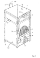
- Fig. 1 is a diagrammatic perspective view of an embodiment of the device according to the invention, showing in particular the exterior thereof.
- This device 10 comprises a frame 100 which in this case is provided with steel side walls screwed thereto and having a thickness of approximately 1.5 mm.
- a part of the device located underneath the latter forms a combustion chamber that can be closed off by means of a plate fitted with a handle 24.
- An air inlet 15 in the form of a perforated plate is present therein. Behind the latter plate there is a similar plate accommodated in a guide rail such that it can be shifted to and fro therein from the exterior by means of a pin in a slot (not shown), so that the air supply 15 can be controlled between a maximum value and zero. The quantity of heat and the heat distribution can thus be controlled to a certain extent in this manner.
- the cover 7 can be set with an opening (of increasing width).
- the combustion gases 40 leave the device 10 via an exhaust pipe 17. Under the combustion chamber there is a space 31 for storing spare fuel 30, for example wood.
- the device 10 is provided at its lower side with two or more wheels so that it can be easily moved.
- the device 10 may be further provided with one or more handles 21 fitted to the sides or rear of the device 10.
- the device 10 in this example is approximately 50 cm wide, 50 cm deep, and 100 to 120 cm high, the plateau being present at the former height and the cover 7 at the latter.
- Fig. 2 is a diagrammatic perspective view, partly broken away, of the device of Fig. 1 , showing in particular the interior thereof.
- the two plateaus 1, 2 for the preparation of food 11, 12 are particularly clearly visible herein.
- the food 11 comprises hamburgers and sausages here, whereas the food 12 comprises a pizza.
- the two plateaus 1, 2 are formed from stone slabs of a few centimeters thickness.
- the plateau 1 is made, for example, of granite or serpentino, and the further plateau 2 comprises a ceramic material.
- the device 10 is provided with various means for distributing the heat generated in the combustion chamber 14.
- Said means comprise that the further plateau forms part of a bottom of a drawer-type body 8 whose open front adjoins a portion of a front face of the device 10 that can be opened, while two side faces of said body are at some distance from the side walls 5 and a rear face thereof is at some distance from the rear wall of the device 10. Both the side faces and the rear and front faces of the drawer-type body 8 are bounded at the upper side by the plateau 1.
- the heat distribution means further comprise that the bottom 3 of the further plateau is double-walled.
- the walls 3A, 3B of the bottom 3 here have a triangular cross-section (height approximately 10 to 15 cm), i.e. viewed perpendicularly to the front (and rear) wall of the device 10.
- Guide strips 6A, 6B have been provided in the path of the combustion gases 140 in order to optimize the heat transfer from the combustion gases 140 to the oven chamber 8 and thus to the plateaus 1, 2.
- Strips 6A guide the combustion gases 140 from the front to the rear and from below to above, while strips 6B, which are present at the rear portions of the sides of the oven chamber 8 and at the rear thereof, slow down the combustion gases 140 and/or guide them from the rear to the front.
- the strips 6A, 6B have a fixed shape and position in the example given here. Said strips may be made adjustable in order to render the heat distribution in the device 10 more controllable, in which case said shape and position can be modified from the outside.
- the temperature of the upper plateau 1 in the device 10 lies between 100 °C and 200 °C, which makes it suitable for the preparation of food 11 such as fish, meat, vegetables, and pancakes.
- the temperature at the further plateau 2 lies between 200 °C and 300 °C, so that it is suitable for the preparation of food comprising dough products such as pizzas.
- the plateau may comprise not only a closed plate or a barbecue grill, but also a plate provided with one or several (larger) openings in which, for example, a wok-type frying pan can be placed, for example for the preparation of vegetables.
- the device is also suitable for use as a terrace heater. This may take place already during barbecuing, in which case the additional heat losses involved may be compensated by a greater fuel consumption. It may also take place while the device is not in use as a barbecue. In that case the door of the air inlet may be left open, so that an open fireplace effect is created.
Landscapes
- Engineering & Computer Science (AREA)
- Food Science & Technology (AREA)
- Baking, Grill, Roasting (AREA)
- General Preparation And Processing Of Foods (AREA)
Abstract
Description
- The invention relates to a device for the outdoor preparation of food by heating, comprising a movable frame with a combustion chamber arranged therein, which chamber is provided with an air inlet and is connected to an outlet for combustion gases adjacent an upper side of the device, and comprising a plateau which is located above the combustion chamber and on which food to be prepared can be placed. The invention also relates to a method for the outdoor preparation of food by heating.
- Such a device is commonly called a barbecue and the method is called barbecuing, but these expressions are too limited to do justice to the present invention. Thus the device can be operated on various fuels, such as gaseous, liquid, and solid fuels. Examples of the latter type are coal, wood, and charcoal. It is noted that, although less obvious, such a device may also be operated with electrically generated heat. In that case the expression 'combustion chamber' should read 'heating chamber' and the expression 'combustion gases' should read 'hot air'.
- Such a device should be suitable for various users with various wishes, i.e. the user himself can decide what kind of food he wishes to prepare by heating. The device should furthermore have a good safety such that a user, in particular a youthful person or a child, is not exposed to unacceptable risks. The device should also be compact and comparatively light in weight, so that it can be easily moved to various locations outdoors such as in the garden, on the terrace, and under a veranda.
- Such a device is known from the American patent
US 2,894,448 published on July 14th, 1959 . This discloses (cf.Fig. 2 of the cited patent) a substantially cylindrical device that comprises a cooking appliance that is suitable for preparing various kinds of food by heating. Smoking of fish or meat is also mentioned as a possible application. The device comprises a plateau on which food to be prepared can be placed, and there are projections at three different distances from the combustion chamber: immediately above it, approximately at the upper side of the device, and in an intermediate position. Roughly in this intermediate position it is possible to insert a removable attachment that acts as a drain for fat dripping from the food located on the plateau in the uppermost position. The plateau in this case comprises a grill through which fat from the food under preparation can drop down. - It is a disadvantage of the known device that it is comparatively unwieldy in use. The device is not suitable for the preparation of all kinds of food. Neither is the safety as good as it could be.
- It is accordingly an object of the present invention to provide a device as described above that is comparatively easy to use, that is suitable for preparing many kinds of food products, and that has an excellent safety.
- According to the invention, a device of the kind mentioned in the opening paragraph is for this purpose characterized in that the device comprises a further plateau on which further food to be prepared can be placed and which is located between the combustion chamber and the plateau, and in that the device is provided with heat distribution means for distributing the heat generated in the combustion chamber over the plateau and the further plateau. The invention is based on the following two surprising recognitions. First, two fixed positions for the preparation of food, one close to the combustion chamber and one approximately at the upper level of the device, have the result that a large number of different food products can be prepared simultaneously. The provision of heat distribution means achieves that the temperature distribution of the two plateaus is suitable for the preparation of the envisaged foods. Thus it is possible on the upper plateau to prepare meat, fish, vegetables, and pancakes at a temperature that lies between approximately 100 °C and 200 °C. On the lower plateau situated closest to the combustion chamber, at a temperature that lies between approximately 200 °C and 300 °C, it is possible to prepare dough products such as pizzas. The latter is particularly remarkable because the preparation of pizzas is highly critical. On the one hand the bottom should be nicely browned and crunchy, while on the other hand the top of a pizza should be exactly done and chewy. Products such as vegetables, meat, fish, and cheese present on such a pizza are very critical in this respect, in particular the cheese. Where a barbecue is mainly designed for preparing meat products, the preparation of pizzas forms a welcome addition to the barbecue menu. This is particularly relevant in the case of children, who are often very fond of pizzas. The wider possibilities may also be attractive for adults, however, for example for vegetarians.
- In a preferred embodiment, the heat distribution means comprise that the bottom of the further plateau is double-walled. It is achieved thereby that the bottom of a pizza does not become too hot, so that burning thereof can be avoided. The heat not supplied directly to the pizza may be distributed through the device in a different manner so as to realize an optimum temperature distribution over the two plateaus. It is noted in this connection that the expression 'heat distribution' herein denotes the spreading and dividing of heat in all three forms in which this is known, and which are also prevalent in a barbecue: firstly radiation of heat, secondly conduction of heat, and thirdly convection of heat.
- Preferably, the bottom of the further plateau has a shape that projects in its center towards the combustion chamber, viewed in a cross-section taken perpendicularly to a projected direction from the air inlet to the outlet. As a result of this, various forms of heat are transported upwards to the right and to the left of the further plateau. The component that projects downwards in the center may be formed by a plate that may be solid or double-walled. In a favorable embodiment, a double-walled bottom has a triangular shape viewed in said cross-section. Good results are also obtainable with a form that somewhat deviates from the triangular shape. Furthermore, a - preferably double-walled - downwardly protruding shape may be advantageously used with another geometry in said cross-section such as a round or oval shape.
- In a further favorable embodiment, the heat distribution means comprise an insulated design of the side walls of the device, while the combustion gases are guided mainly on either side of the further plateau towards the outlet, which is situated close to and below the first plateau. Such an insulated design preferably comprises that side walls of the device are of a double-walled construction at least at the level of the upper portion of the combustion chamber and all components of the device located above said upper portion. More heat is thus available for heating food on both plateaus.
- The heat distribution means furthermore advantageously comprise guide strips that extend in the path of the combustion gases on either side of the further plateau. The combustion gases and the heat contained therein can thus be guided, for example, from the front to the rear, but also a return path or a deceleration are among the possibilities. The heat distribution can be optimized in this manner.
- In a further embodiment, the heat distribution means comprise a cover that can be placed over the plateau. The temperature of the plateau can be raised by means of this.
- In a major embodiment, the heat distribution means comprise that the further plateau forms part of a bottom of a drawer-type body of which an open front adjoins a portion of a front face of the device that can be opened, of which two side faces are at some distance from the side walls, and of which a rear face is at some distance from the rear wall of the device, wherein the side faces, the rear face, as well as the front face are bounded on the upper side by the plateau. In this manner it is possible in particular to optimize the temperature and the temperature distribution in the heating chamber above the further plateau for the preparation of pizzas. An important additional advantage of this embodiment is that flames and combustion gases can never leave the device in principle. This is because the lower plateau in particular will preferably be formed by a closed plate. Sudden flames and/or combustion gases will then never come into direct contact with a user of the device even if the upper plateau is formed as an open barbecue grill. Such flames and gases will normally leave the device through an exhaust pipe that is preferably fitted to the gas outlet. A device according to the invention is thus not only very effective, but also very safe to use.
- For this purpose, the device will be provided with suitable sealing means, for example in the form of a heat-resistant cement, between the drawer-type body and the other parts of the device, among these in particular the gas channels on either side of and behind the combustion chamber formed by the drawer-type body.
- In a favorable modification, both the plateau and the further plateau comprise a closed plate. This may be a metal plate, such as a cast iron or stainless steel plate, but preferably a slab of (natural) stone is used. The plateau is then preferably made of a natural stone such as granite or serpentino, whereas the further plateau comprises a ceramic material.
- Both the shape and the geometry of the device may be varied. Preferably it has a substantially rectangular shape when viewed in projection, wherein the air inlet and the outlet for the combustion gases lie at mutually opposed sides of the device, preferably at the front and at the rear of the device, respectively.
- The device may advantageously be made mobile in that it is provided with two or more wheels so as to make it easier to move.
- According to the invention, a method for the outdoor preparation of food by heating, which method utilizes a device which is provided with a movable frame with a combustion chamber arranged therein, which chamber is provided with an air inlet and is connected to an outlet for combustion gases adjacent an upper side of the device, and which device is provided with a plateau which is located above the combustion chamber and on which food to be prepared can be placed, is characterized in that the device is provided with a further plateau on which further food to be prepared can be placed and which is located between the combustion chamber and the plateau, and in that the device is provided with heat distribution means for distributing the heat generated in the combustion chamber over the plateau and the further plateau. The invention may thus also be advantageously used in the catering and/or restaurant business. A device according to the invention may advantageously be used for this. The device may be increased in size especially for such applications (in particular made wider). The device may advantageously be made of a double construction within one frame. This not only provides the capacity increase desired for said applications, it also provides a greater freedom, for example for placing a barbecue grill next to a stone plate at the level of the higher plateau. A cover over these plates may also be of a double design then.
- These and other aspects of the invention will become apparent from and be explained in more detail with reference to the embodiments to be described below. Reference is made to the drawings, in which:
-
Fig. 1 is a diagrammatic perspective view of an embodiment of the device according to the invention, showing in particular the exterior thereof, and -
Fig. 2 is a diagrammatic perspective view, partly broken away, of the device ofFig. 1 , showing in particular the interior thereof. -
Fig. 1 is a diagrammatic perspective view of an embodiment of the device according to the invention, showing in particular the exterior thereof. Thisdevice 10 comprises aframe 100 which in this case is provided with steel side walls screwed thereto and having a thickness of approximately 1.5 mm. On top of thedevice 10 there is acover 7 that is provided with atemperature indicator 20 and ahandle 22, at the approximate level of which below the cover we find the plateau for the preparation of food. Behind a part of thedevice 10 that can be closed off with aflap 23 there is an oven space on whose bottom the further plateau for the preparation of further food is formed. A part of the device located underneath the latter forms a combustion chamber that can be closed off by means of a plate fitted with ahandle 24. Anair inlet 15 in the form of a perforated plate is present therein. Behind the latter plate there is a similar plate accommodated in a guide rail such that it can be shifted to and fro therein from the exterior by means of a pin in a slot (not shown), so that theair supply 15 can be controlled between a maximum value and zero. The quantity of heat and the heat distribution can thus be controlled to a certain extent in this manner. To control the temperature of the upper food plateau thecover 7 can be set with an opening (of increasing width). Thecombustion gases 40 leave thedevice 10 via anexhaust pipe 17. Under the combustion chamber there is aspace 31 for storingspare fuel 30, for example wood. Thedevice 10 is provided at its lower side with two or more wheels so that it can be easily moved. To facilitate this moving, thedevice 10 may be further provided with one ormore handles 21 fitted to the sides or rear of thedevice 10. Thedevice 10 in this example is approximately 50 cm wide, 50 cm deep, and 100 to 120 cm high, the plateau being present at the former height and thecover 7 at the latter. -
Fig. 2 is a diagrammatic perspective view, partly broken away, of the device ofFig. 1 , showing in particular the interior thereof. The twoplateaus food food 11 comprises hamburgers and sausages here, whereas thefood 12 comprises a pizza. The twoplateaus plateau 1 is made, for example, of granite or serpentino, and thefurther plateau 2 comprises a ceramic material. Thedevice 10 is provided with various means for distributing the heat generated in thecombustion chamber 14. - Said means comprise that the further plateau forms part of a bottom of a drawer-
type body 8 whose open front adjoins a portion of a front face of thedevice 10 that can be opened, while two side faces of said body are at some distance from theside walls 5 and a rear face thereof is at some distance from the rear wall of thedevice 10. Both the side faces and the rear and front faces of the drawer-type body 8 are bounded at the upper side by theplateau 1. In this example, the heat distribution means further comprise that the bottom 3 of the further plateau is double-walled. Thewalls device 10. As a result, the flames present in the combustion chamber and the air sucked in through theair inlet 14 are guided to the left and to the right. Air is also admitted on the left and on the right of thecombustion chamber 14, and the admitted air and subsequently the combustion gases have been indicated here withthinner arrows 40. - Thus it is apparent that (additional)
air 40 is sucked on left and right of theoven chamber 8. This air will rise together with thecombustion gases 140 owing to convection, whereby theoven chamber 8 is optimally heated. Theside walls 5 of thedevice 10 and the rear wall thereof have been made double-walled for this purpose at least over the relevant portion of thedevice 10, i.e. from approximately halfway the combustion chamber up to theplateau 1. This keeps the outside of thedevice 10 comparatively cool while also increasing the amount of heat available for heating theplateaus combustion gases 140 are finally discharged at the rear of thedevice 10 through anoutlet 16 to the exhaust pipe (not shown) mentioned above. Guide strips 6A, 6B have been provided in the path of thecombustion gases 140 in order to optimize the heat transfer from thecombustion gases 140 to theoven chamber 8 and thus to theplateaus combustion gases 140 from the front to the rear and from below to above, whilestrips 6B, which are present at the rear portions of the sides of theoven chamber 8 and at the rear thereof, slow down thecombustion gases 140 and/or guide them from the rear to the front. Thestrips device 10 more controllable, in which case said shape and position can be modified from the outside. - The temperature of the
upper plateau 1 in thedevice 10 according to this embodiment lies between 100 °C and 200 °C, which makes it suitable for the preparation offood 11 such as fish, meat, vegetables, and pancakes. The temperature at thefurther plateau 2 lies between 200 °C and 300 °C, so that it is suitable for the preparation of food comprising dough products such as pizzas. - The invention has been described above with reference to preferred embodiments thereof. Those skilled in the art will realize that many modifications and changes may be applied thereto without departing from the scope of the accompanying claims. Such preferred embodiments should accordingly be regarded as illustrative rather than limitative, and no limitations should be inferred therefrom other than those expressly stated in the accompanying claims.
- Thus it is noted that the plateau may comprise not only a closed plate or a barbecue grill, but also a plate provided with one or several (larger) openings in which, for example, a wok-type frying pan can be placed, for example for the preparation of vegetables.
- It is finally noted that the device is also suitable for use as a terrace heater. This may take place already during barbecuing, in which case the additional heat losses involved may be compensated by a greater fuel consumption. It may also take place while the device is not in use as a barbecue. In that case the door of the air inlet may be left open, so that an open fireplace effect is created.
Claims (15)
- A device (10) for the outdoor preparation of food (11, 12) by heating, comprising a movable frame (100) with a combustion chamber (14) arranged therein, which chamber is provided with an air inlet (15) and is connected to an outlet (16) for combustion gases adjacent an upper side of the device (10), and comprising a plateau (1) which is located above the combustion chamber (14) and on which food (11) to be prepared can be placed, characterized in that the device (10) comprises a further plateau (2) on which further food (12) to be prepared can be placed and which is located between the combustion chamber (14) and the plateau (1), and in that the device (10) is provided with heat distribution means (3, 4, 5, 6, 7, 8) for distributing the heat generated in the combustion chamber (14) over the plateau (1) and the further plateau (2).
- A device as claimed in claim 1, characterized in that the heat distribution means comprise that the bottom (3) of the further plateau (2) is double-walled (3A, 3B).
- A device as claimed in claim 2, characterized in that the bottom (3) has a shape (4) that projects in its center towards the combustion chamber (14) when viewed in a cross-section taken perpendicularly to a projected direction from the air inlet (15) to the outlet (16) for the combustion gases.
- A device as claimed in claim 3, characterized in that the bottom (3) has a triangular shape (4) when viewed in said cross-section.
- A device as claimed in any one of the preceding claims, characterized in that the heat distribution means comprise an insulated design of the side walls (5) of the device (10), while the combustion gases are guided mainly on either side of the further plateau (2) towards the outlet (16), which is situated close to and below the first plateau (1).
- A device as claimed in claim 5, characterized in that the heat distribution means comprise guide strips (6A, 6B) that extend in the path of the combustion gases on either side of the further plateau (2).
- A device as claimed in any one of the preceding claims, characterized in that the heat distribution means comprise a cover (7) that can be placed over the plateau (1).
- A device as claimed in any one of the preceding claims, characterized in that the heat distribution means comprise that the further plateau (2) forms part of a bottom of a drawer-type body (8) of which an open front adjoins a portion of a front face of the device that can be opened, of which two side faces are at some distance from the side walls (5), and of which a rear face is at some distance from the rear wall of the device, wherein the side faces, the rear face, as well as the front face of the drawer-type body (8) are bounded on the upper side by the plateau (1).
- A device as claimed in any one of the preceding claims, characterized in that the plateau (1) and the further plateau (2) each comprise a closed plate.
- A device as claimed in claim 9, characterized in that the plateau (1) comprises a slab of natural stone and the further plateau (2) comprises a ceramic plate.
- A device as claimed in any one of the preceding claims, characterized in that it has a substantially rectangular shape when viewed in projection, wherein the air inlet (15) and the outlet (16) for the combustion gases lie at mutually opposed sides of the device.
- A device as claimed in any one of the preceding claims, characterized in that the temperature adjacent the plateau (1) lies between 100 °C and 200 °C during operation, so that this plateau is suitable for the preparation of food such as fish, meat, vegetables, and pancakes.
- A device as claimed in any one of the preceding claims, characterized in that the temperature adjacent the further plateau (2) lies between 200 °C and 300 °C during operation, so that this plateau is suitable for the preparation of food that contains dough products, such as pizzas.
- A device as claimed in any one of the preceding claims, characterized in that the device is provided with two or more wheels (8).
- A method for the outdoor preparation of food (11, 12) by heating, which method utilizes a device (10) which is provided with a movable frame (100) with a combustion chamber (14) arranged therein, which chamber is provided with an air inlet (15) and is connected to an outlet (16) for combustion gases adjacent an upper side of the device (10), and which device (10) is provided with a plateau (1) which is located above the combustion chamber (14) and on which food (11) to be prepared can be placed, characterized in that the device (10) is provided with a further plateau (2) on which further food (12) to be prepared can be placed and which is located between the combustion chamber (14) and the plateau (1), and in that the device (10) is provided with heat distribution means (3, 4, 5, 6, 7, 8) for distributing the heat generated in the combustion chamber (14) over the plateau (1) and the further plateau (2).
Applications Claiming Priority (1)
| Application Number | Priority Date | Filing Date | Title |
|---|---|---|---|
| NL2002395A NL2002395C2 (en) | 2009-01-05 | 2009-01-05 | DEVICE AND METHOD FOR PREPARING FOOD OUTDOORS |
Publications (2)
| Publication Number | Publication Date |
|---|---|
| EP2204115A1 true EP2204115A1 (en) | 2010-07-07 |
| EP2204115B1 EP2204115B1 (en) | 2011-08-24 |
Family
ID=40942379
Family Applications (1)
| Application Number | Title | Priority Date | Filing Date |
|---|---|---|---|
| EP09179434A Not-in-force EP2204115B1 (en) | 2009-01-05 | 2009-12-16 | Device and method for the outdoor preparation of food |
Country Status (3)
| Country | Link |
|---|---|
| EP (1) | EP2204115B1 (en) |
| AT (1) | ATE521266T1 (en) |
| NL (1) | NL2002395C2 (en) |
Families Citing this family (3)
| Publication number | Priority date | Publication date | Assignee | Title |
|---|---|---|---|---|
| US12035845B1 (en) | 2023-04-26 | 2024-07-16 | Sharkninja Operating Llc | Systems and methods for cooking pizza |
| US12372247B2 (en) | 2023-04-26 | 2025-07-29 | Sharkninja Operating Llc | Systems and methods for cooking pizza |
| USD1104596S1 (en) | 2023-05-31 | 2025-12-09 | Sharkninja Operating Llc | Cooking device |
Citations (6)
| Publication number | Priority date | Publication date | Assignee | Title |
|---|---|---|---|---|
| US3791370A (en) * | 1971-04-13 | 1974-02-12 | Italiana Superior Srl Soc | Device for cooking foods |
| FR2494976A1 (en) * | 1980-11-28 | 1982-06-04 | Oureval | VERSATILE DOUBLE COOKING OVEN |
| EP0626055A1 (en) * | 1992-01-21 | 1994-11-30 | Jaime Sans | Small oven for grilling food on gas cooker burners. |
| US20020017290A1 (en) * | 1998-12-18 | 2002-02-14 | Hines Robert S. | Cooking grill with baking oven insert |
| FR2819708A1 (en) * | 2001-01-25 | 2002-07-26 | Georges Digirolamo | PIZZA BARBECUE OVEN |
| US20050039612A1 (en) * | 2003-08-22 | 2005-02-24 | Sean Patrick Denny | Multiple bottom outdoor grill accessory |
-
2009
- 2009-01-05 NL NL2002395A patent/NL2002395C2/en not_active IP Right Cessation
- 2009-12-16 AT AT09179434T patent/ATE521266T1/en not_active IP Right Cessation
- 2009-12-16 EP EP09179434A patent/EP2204115B1/en not_active Not-in-force
Patent Citations (6)
| Publication number | Priority date | Publication date | Assignee | Title |
|---|---|---|---|---|
| US3791370A (en) * | 1971-04-13 | 1974-02-12 | Italiana Superior Srl Soc | Device for cooking foods |
| FR2494976A1 (en) * | 1980-11-28 | 1982-06-04 | Oureval | VERSATILE DOUBLE COOKING OVEN |
| EP0626055A1 (en) * | 1992-01-21 | 1994-11-30 | Jaime Sans | Small oven for grilling food on gas cooker burners. |
| US20020017290A1 (en) * | 1998-12-18 | 2002-02-14 | Hines Robert S. | Cooking grill with baking oven insert |
| FR2819708A1 (en) * | 2001-01-25 | 2002-07-26 | Georges Digirolamo | PIZZA BARBECUE OVEN |
| US20050039612A1 (en) * | 2003-08-22 | 2005-02-24 | Sean Patrick Denny | Multiple bottom outdoor grill accessory |
Also Published As
| Publication number | Publication date |
|---|---|
| ATE521266T1 (en) | 2011-09-15 |
| NL2002395C2 (en) | 2010-07-06 |
| EP2204115B1 (en) | 2011-08-24 |
Similar Documents
| Publication | Publication Date | Title |
|---|---|---|
| US5313877A (en) | Barbecue grill with controlled heat distribution | |
| US8261732B2 (en) | Cooking grill | |
| US6187359B1 (en) | Method and apparatus for baking foods in a barbeque grill | |
| US9314134B2 (en) | Electrical portable broiler | |
| US5380986A (en) | Multi-purpose electric fast cooking apparatus | |
| EP2901901B1 (en) | Cooking apparatus | |
| US6268592B1 (en) | Electric grill plate appliance for tortilla cuisine | |
| US3581731A (en) | Portable cooking unit | |
| US8993026B2 (en) | Infrared portable broiler | |
| US20070221191A1 (en) | Outdoor oven | |
| US20060102167A1 (en) | Pizza oven for grill | |
| JP6057361B1 (en) | Pottery cooker | |
| US20140261012A1 (en) | Cooking grill having rack supporting individual grilling modules | |
| EP3735879A1 (en) | Compound stove of smoke-free grill and pizza oven | |
| EP2204115B1 (en) | Device and method for the outdoor preparation of food | |
| KR102076911B1 (en) | Roasting apparatus | |
| US20020152900A1 (en) | Radiant heat sausage cook plate | |
| KR102586493B1 (en) | Roasting apparatus | |
| US3832990A (en) | Portable broiler | |
| JP4048324B2 (en) | Cooking device | |
| JP7284601B2 (en) | Cookware, heat cookers, and cooking nets | |
| KR20160084602A (en) | smoking barbecue equipment using indirect heat | |
| CN205625660U (en) | Gas griddle | |
| CN217723296U (en) | Multifunctional furnace | |
| KR102425196B1 (en) | User friendly induction cooker |
Legal Events
| Date | Code | Title | Description |
|---|---|---|---|
| PUAI | Public reference made under article 153(3) epc to a published international application that has entered the european phase |
Free format text: ORIGINAL CODE: 0009012 |
|
| AK | Designated contracting states |
Kind code of ref document: A1 Designated state(s): AT BE BG CH CY CZ DE DK EE ES FI FR GB GR HR HU IE IS IT LI LT LU LV MC MK MT NL NO PL PT RO SE SI SK SM TR |
|
| AX | Request for extension of the european patent |
Extension state: AL BA RS |
|
| 17P | Request for examination filed |
Effective date: 20110107 |
|
| GRAP | Despatch of communication of intention to grant a patent |
Free format text: ORIGINAL CODE: EPIDOSNIGR1 |
|
| RIC1 | Information provided on ipc code assigned before grant |
Ipc: A47J 37/07 20060101AFI20110204BHEP |
|
| GRAS | Grant fee paid |
Free format text: ORIGINAL CODE: EPIDOSNIGR3 |
|
| GRAA | (expected) grant |
Free format text: ORIGINAL CODE: 0009210 |
|
| AK | Designated contracting states |
Kind code of ref document: B1 Designated state(s): AT BE BG CH CY CZ DE DK EE ES FI FR GB GR HR HU IE IS IT LI LT LU LV MC MK MT NL NO PL PT RO SE SI SK SM TR |
|
| REG | Reference to a national code |
Ref country code: GB Ref legal event code: FG4D |
|
| REG | Reference to a national code |
Ref country code: CH Ref legal event code: EP |
|
| REG | Reference to a national code |
Ref country code: IE Ref legal event code: FG4D Ref country code: NL Ref legal event code: T3 |
|
| REG | Reference to a national code |
Ref country code: DE Ref legal event code: R096 Ref document number: 602009002266 Country of ref document: DE Effective date: 20111117 |
|
| LTIE | Lt: invalidation of european patent or patent extension |
Effective date: 20110824 |
|
| PG25 | Lapsed in a contracting state [announced via postgrant information from national office to epo] |
Ref country code: HR Free format text: LAPSE BECAUSE OF FAILURE TO SUBMIT A TRANSLATION OF THE DESCRIPTION OR TO PAY THE FEE WITHIN THE PRESCRIBED TIME-LIMIT Effective date: 20110824 Ref country code: LT Free format text: LAPSE BECAUSE OF FAILURE TO SUBMIT A TRANSLATION OF THE DESCRIPTION OR TO PAY THE FEE WITHIN THE PRESCRIBED TIME-LIMIT Effective date: 20110824 Ref country code: NO Free format text: LAPSE BECAUSE OF FAILURE TO SUBMIT A TRANSLATION OF THE DESCRIPTION OR TO PAY THE FEE WITHIN THE PRESCRIBED TIME-LIMIT Effective date: 20111124 Ref country code: IS Free format text: LAPSE BECAUSE OF FAILURE TO SUBMIT A TRANSLATION OF THE DESCRIPTION OR TO PAY THE FEE WITHIN THE PRESCRIBED TIME-LIMIT Effective date: 20111224 Ref country code: FI Free format text: LAPSE BECAUSE OF FAILURE TO SUBMIT A TRANSLATION OF THE DESCRIPTION OR TO PAY THE FEE WITHIN THE PRESCRIBED TIME-LIMIT Effective date: 20110824 Ref country code: PT Free format text: LAPSE BECAUSE OF FAILURE TO SUBMIT A TRANSLATION OF THE DESCRIPTION OR TO PAY THE FEE WITHIN THE PRESCRIBED TIME-LIMIT Effective date: 20111226 Ref country code: SE Free format text: LAPSE BECAUSE OF FAILURE TO SUBMIT A TRANSLATION OF THE DESCRIPTION OR TO PAY THE FEE WITHIN THE PRESCRIBED TIME-LIMIT Effective date: 20110824 |
|
| REG | Reference to a national code |
Ref country code: AT Ref legal event code: MK05 Ref document number: 521266 Country of ref document: AT Kind code of ref document: T Effective date: 20110824 |
|
| PG25 | Lapsed in a contracting state [announced via postgrant information from national office to epo] |
Ref country code: GR Free format text: LAPSE BECAUSE OF FAILURE TO SUBMIT A TRANSLATION OF THE DESCRIPTION OR TO PAY THE FEE WITHIN THE PRESCRIBED TIME-LIMIT Effective date: 20111125 Ref country code: SI Free format text: LAPSE BECAUSE OF FAILURE TO SUBMIT A TRANSLATION OF THE DESCRIPTION OR TO PAY THE FEE WITHIN THE PRESCRIBED TIME-LIMIT Effective date: 20110824 Ref country code: LV Free format text: LAPSE BECAUSE OF FAILURE TO SUBMIT A TRANSLATION OF THE DESCRIPTION OR TO PAY THE FEE WITHIN THE PRESCRIBED TIME-LIMIT Effective date: 20110824 Ref country code: PL Free format text: LAPSE BECAUSE OF FAILURE TO SUBMIT A TRANSLATION OF THE DESCRIPTION OR TO PAY THE FEE WITHIN THE PRESCRIBED TIME-LIMIT Effective date: 20110824 Ref country code: AT Free format text: LAPSE BECAUSE OF FAILURE TO SUBMIT A TRANSLATION OF THE DESCRIPTION OR TO PAY THE FEE WITHIN THE PRESCRIBED TIME-LIMIT Effective date: 20110824 Ref country code: CY Free format text: LAPSE BECAUSE OF FAILURE TO SUBMIT A TRANSLATION OF THE DESCRIPTION OR TO PAY THE FEE WITHIN THE PRESCRIBED TIME-LIMIT Effective date: 20110824 |
|
| PG25 | Lapsed in a contracting state [announced via postgrant information from national office to epo] |
Ref country code: CZ Free format text: LAPSE BECAUSE OF FAILURE TO SUBMIT A TRANSLATION OF THE DESCRIPTION OR TO PAY THE FEE WITHIN THE PRESCRIBED TIME-LIMIT Effective date: 20110824 Ref country code: SK Free format text: LAPSE BECAUSE OF FAILURE TO SUBMIT A TRANSLATION OF THE DESCRIPTION OR TO PAY THE FEE WITHIN THE PRESCRIBED TIME-LIMIT Effective date: 20110824 |
|
| PG25 | Lapsed in a contracting state [announced via postgrant information from national office to epo] |
Ref country code: RO Free format text: LAPSE BECAUSE OF FAILURE TO SUBMIT A TRANSLATION OF THE DESCRIPTION OR TO PAY THE FEE WITHIN THE PRESCRIBED TIME-LIMIT Effective date: 20110824 Ref country code: IT Free format text: LAPSE BECAUSE OF FAILURE TO SUBMIT A TRANSLATION OF THE DESCRIPTION OR TO PAY THE FEE WITHIN THE PRESCRIBED TIME-LIMIT Effective date: 20110824 Ref country code: EE Free format text: LAPSE BECAUSE OF FAILURE TO SUBMIT A TRANSLATION OF THE DESCRIPTION OR TO PAY THE FEE WITHIN THE PRESCRIBED TIME-LIMIT Effective date: 20110824 |
|
| PG25 | Lapsed in a contracting state [announced via postgrant information from national office to epo] |
Ref country code: DK Free format text: LAPSE BECAUSE OF FAILURE TO SUBMIT A TRANSLATION OF THE DESCRIPTION OR TO PAY THE FEE WITHIN THE PRESCRIBED TIME-LIMIT Effective date: 20110824 |
|
| PLBE | No opposition filed within time limit |
Free format text: ORIGINAL CODE: 0009261 |
|
| STAA | Information on the status of an ep patent application or granted ep patent |
Free format text: STATUS: NO OPPOSITION FILED WITHIN TIME LIMIT |
|
| PG25 | Lapsed in a contracting state [announced via postgrant information from national office to epo] |
Ref country code: MC Free format text: LAPSE BECAUSE OF NON-PAYMENT OF DUE FEES Effective date: 20111231 |
|
| 26N | No opposition filed |
Effective date: 20120525 |
|
| REG | Reference to a national code |
Ref country code: DE Ref legal event code: R097 Ref document number: 602009002266 Country of ref document: DE Effective date: 20120525 |
|
| REG | Reference to a national code |
Ref country code: IE Ref legal event code: MM4A |
|
| PG25 | Lapsed in a contracting state [announced via postgrant information from national office to epo] |
Ref country code: IE Free format text: LAPSE BECAUSE OF NON-PAYMENT OF DUE FEES Effective date: 20111216 |
|
| PG25 | Lapsed in a contracting state [announced via postgrant information from national office to epo] |
Ref country code: MK Free format text: LAPSE BECAUSE OF FAILURE TO SUBMIT A TRANSLATION OF THE DESCRIPTION OR TO PAY THE FEE WITHIN THE PRESCRIBED TIME-LIMIT Effective date: 20110824 Ref country code: MT Free format text: LAPSE BECAUSE OF FAILURE TO SUBMIT A TRANSLATION OF THE DESCRIPTION OR TO PAY THE FEE WITHIN THE PRESCRIBED TIME-LIMIT Effective date: 20110824 |
|
| PG25 | Lapsed in a contracting state [announced via postgrant information from national office to epo] |
Ref country code: SM Free format text: LAPSE BECAUSE OF FAILURE TO SUBMIT A TRANSLATION OF THE DESCRIPTION OR TO PAY THE FEE WITHIN THE PRESCRIBED TIME-LIMIT Effective date: 20110824 Ref country code: ES Free format text: LAPSE BECAUSE OF FAILURE TO SUBMIT A TRANSLATION OF THE DESCRIPTION OR TO PAY THE FEE WITHIN THE PRESCRIBED TIME-LIMIT Effective date: 20111205 |
|
| PG25 | Lapsed in a contracting state [announced via postgrant information from national office to epo] |
Ref country code: LU Free format text: LAPSE BECAUSE OF NON-PAYMENT OF DUE FEES Effective date: 20111216 |
|
| PG25 | Lapsed in a contracting state [announced via postgrant information from national office to epo] |
Ref country code: BG Free format text: LAPSE BECAUSE OF FAILURE TO SUBMIT A TRANSLATION OF THE DESCRIPTION OR TO PAY THE FEE WITHIN THE PRESCRIBED TIME-LIMIT Effective date: 20111124 |
|
| PG25 | Lapsed in a contracting state [announced via postgrant information from national office to epo] |
Ref country code: TR Free format text: LAPSE BECAUSE OF FAILURE TO SUBMIT A TRANSLATION OF THE DESCRIPTION OR TO PAY THE FEE WITHIN THE PRESCRIBED TIME-LIMIT Effective date: 20110824 |
|
| PG25 | Lapsed in a contracting state [announced via postgrant information from national office to epo] |
Ref country code: HU Free format text: LAPSE BECAUSE OF FAILURE TO SUBMIT A TRANSLATION OF THE DESCRIPTION OR TO PAY THE FEE WITHIN THE PRESCRIBED TIME-LIMIT Effective date: 20110824 |
|
| REG | Reference to a national code |
Ref country code: CH Ref legal event code: PL |
|
| PG25 | Lapsed in a contracting state [announced via postgrant information from national office to epo] |
Ref country code: LI Free format text: LAPSE BECAUSE OF NON-PAYMENT OF DUE FEES Effective date: 20131231 Ref country code: CH Free format text: LAPSE BECAUSE OF NON-PAYMENT OF DUE FEES Effective date: 20131231 |
|
| REG | Reference to a national code |
Ref country code: FR Ref legal event code: PLFP Year of fee payment: 7 |
|
| REG | Reference to a national code |
Ref country code: FR Ref legal event code: PLFP Year of fee payment: 8 |
|
| REG | Reference to a national code |
Ref country code: FR Ref legal event code: PLFP Year of fee payment: 9 |
|
| PGFP | Annual fee paid to national office [announced via postgrant information from national office to epo] |
Ref country code: NL Payment date: 20221226 Year of fee payment: 14 Ref country code: GB Payment date: 20221227 Year of fee payment: 14 Ref country code: FR Payment date: 20221227 Year of fee payment: 14 |
|
| PGFP | Annual fee paid to national office [announced via postgrant information from national office to epo] |
Ref country code: BE Payment date: 20221227 Year of fee payment: 14 |
|
| PGFP | Annual fee paid to national office [announced via postgrant information from national office to epo] |
Ref country code: DE Payment date: 20221228 Year of fee payment: 14 |
|
| REG | Reference to a national code |
Ref country code: DE Ref legal event code: R119 Ref document number: 602009002266 Country of ref document: DE |
|
| REG | Reference to a national code |
Ref country code: NL Ref legal event code: MM Effective date: 20240101 |
|
| GBPC | Gb: european patent ceased through non-payment of renewal fee |
Effective date: 20231216 |
|
| REG | Reference to a national code |
Ref country code: BE Ref legal event code: MM Effective date: 20231231 |
|
| PG25 | Lapsed in a contracting state [announced via postgrant information from national office to epo] |
Ref country code: NL Free format text: LAPSE BECAUSE OF NON-PAYMENT OF DUE FEES Effective date: 20240101 |
|
| PG25 | Lapsed in a contracting state [announced via postgrant information from national office to epo] |
Ref country code: NL Free format text: LAPSE BECAUSE OF NON-PAYMENT OF DUE FEES Effective date: 20240101 |
|
| PG25 | Lapsed in a contracting state [announced via postgrant information from national office to epo] |
Ref country code: DE Free format text: LAPSE BECAUSE OF NON-PAYMENT OF DUE FEES Effective date: 20240702 |
|
| PG25 | Lapsed in a contracting state [announced via postgrant information from national office to epo] |
Ref country code: GB Free format text: LAPSE BECAUSE OF NON-PAYMENT OF DUE FEES Effective date: 20231216 |
|
| PG25 | Lapsed in a contracting state [announced via postgrant information from national office to epo] |
Ref country code: BE Free format text: LAPSE BECAUSE OF NON-PAYMENT OF DUE FEES Effective date: 20231231 |
|
| PG25 | Lapsed in a contracting state [announced via postgrant information from national office to epo] |
Ref country code: FR Free format text: LAPSE BECAUSE OF NON-PAYMENT OF DUE FEES Effective date: 20231231 |
|
| PG25 | Lapsed in a contracting state [announced via postgrant information from national office to epo] |
Ref country code: GB Free format text: LAPSE BECAUSE OF NON-PAYMENT OF DUE FEES Effective date: 20231216 Ref country code: FR Free format text: LAPSE BECAUSE OF NON-PAYMENT OF DUE FEES Effective date: 20231231 Ref country code: DE Free format text: LAPSE BECAUSE OF NON-PAYMENT OF DUE FEES Effective date: 20240702 Ref country code: BE Free format text: LAPSE BECAUSE OF NON-PAYMENT OF DUE FEES Effective date: 20231231 |