EP2204082A1 - Electric mower having two-motion activation system - Google Patents
Electric mower having two-motion activation system Download PDFInfo
- Publication number
- EP2204082A1 EP2204082A1 EP09180693A EP09180693A EP2204082A1 EP 2204082 A1 EP2204082 A1 EP 2204082A1 EP 09180693 A EP09180693 A EP 09180693A EP 09180693 A EP09180693 A EP 09180693A EP 2204082 A1 EP2204082 A1 EP 2204082A1
- Authority
- EP
- European Patent Office
- Prior art keywords
- button
- crank
- input member
- switch
- pawl
- Prior art date
- Legal status (The legal status is an assumption and is not a legal conclusion. Google has not performed a legal analysis and makes no representation as to the accuracy of the status listed.)
- Withdrawn
Links
Images




Classifications
-
- A—HUMAN NECESSITIES
- A01—AGRICULTURE; FORESTRY; ANIMAL HUSBANDRY; HUNTING; TRAPPING; FISHING
- A01D—HARVESTING; MOWING
- A01D34/00—Mowers; Mowing apparatus of harvesters
- A01D34/01—Mowers; Mowing apparatus of harvesters characterised by features relating to the type of cutting apparatus
- A01D34/412—Mowers; Mowing apparatus of harvesters characterised by features relating to the type of cutting apparatus having rotating cutters
- A01D34/63—Mowers; Mowing apparatus of harvesters characterised by features relating to the type of cutting apparatus having rotating cutters having cutters rotating about a vertical axis
- A01D34/67—Mowers; Mowing apparatus of harvesters characterised by features relating to the type of cutting apparatus having rotating cutters having cutters rotating about a vertical axis hand-guided by a walking operator
- A01D34/68—Mowers; Mowing apparatus of harvesters characterised by features relating to the type of cutting apparatus having rotating cutters having cutters rotating about a vertical axis hand-guided by a walking operator with motor driven cutters or wheels
- A01D34/6806—Driving mechanisms
- A01D34/6818—Motor starting mechanisms
-
- A—HUMAN NECESSITIES
- A01—AGRICULTURE; FORESTRY; ANIMAL HUSBANDRY; HUNTING; TRAPPING; FISHING
- A01D—HARVESTING; MOWING
- A01D34/00—Mowers; Mowing apparatus of harvesters
- A01D34/01—Mowers; Mowing apparatus of harvesters characterised by features relating to the type of cutting apparatus
- A01D34/412—Mowers; Mowing apparatus of harvesters characterised by features relating to the type of cutting apparatus having rotating cutters
- A01D34/63—Mowers; Mowing apparatus of harvesters characterised by features relating to the type of cutting apparatus having rotating cutters having cutters rotating about a vertical axis
- A01D34/82—Other details
- A01D34/828—Safety devices
-
- H—ELECTRICITY
- H01—ELECTRIC ELEMENTS
- H01H—ELECTRIC SWITCHES; RELAYS; SELECTORS; EMERGENCY PROTECTIVE DEVICES
- H01H3/00—Mechanisms for operating contacts
- H01H3/02—Operating parts, i.e. for operating driving mechanism by a mechanical force external to the switch
- H01H3/20—Operating parts, i.e. for operating driving mechanism by a mechanical force external to the switch wherein an auxiliary movement thereof, or of an attachment thereto, is necessary before the main movement is possible or effective, e.g. for unlatching, for coupling
-
- H—ELECTRICITY
- H01—ELECTRIC ELEMENTS
- H01H—ELECTRIC SWITCHES; RELAYS; SELECTORS; EMERGENCY PROTECTIVE DEVICES
- H01H9/00—Details of switching devices, not covered by groups H01H1/00 - H01H7/00
- H01H9/02—Bases, casings, or covers
- H01H9/06—Casing of switch constituted by a handle serving a purpose other than the actuation of the switch, e.g. by the handle of a vacuum cleaner
-
- H—ELECTRICITY
- H01—ELECTRIC ELEMENTS
- H01H—ELECTRIC SWITCHES; RELAYS; SELECTORS; EMERGENCY PROTECTIVE DEVICES
- H01H9/00—Details of switching devices, not covered by groups H01H1/00 - H01H7/00
- H01H9/02—Bases, casings, or covers
- H01H9/06—Casing of switch constituted by a handle serving a purpose other than the actuation of the switch, e.g. by the handle of a vacuum cleaner
- H01H2009/068—Casing of switch constituted by a handle serving a purpose other than the actuation of the switch, e.g. by the handle of a vacuum cleaner with switches mounted on a handlebar, e.g. for motorcycles, fork lift trucks, etc.
Definitions
- the present disclosure relates to electric outdoor power equipment and more specifically to an electric outdoor power machine having a two-motion activation system.
- An electric outdoor power machine for example a lawn mower
- a machine body supported by wheels and having an output member driven by a motor.
- the motor is powered by a source of electrical power such as a battery.
- An upright assembly extends from the machine body and has a gripping handle.
- a manual input member such as a bail handle is mounted adjacent to the gripping handle and is movable relative to the gripping handle between a deactivated position and an activated position.
- a control assembly that selectively communicates electric power to the output member includes a button supported by a housing on the upright assembly. The button is movable between an unactuated position and an actuated position.
- a button crank is coupled to the button and has an interface portion.
- a switch has a switch input member that is movable between an "ON” position and an “OFF” position. In the “ON” position, the switch electrically connects the source of electrical power with the motor.
- a pawl extends from the bail handle. The switch is moved to the "ON" position by sequential movement of the button into the actuated position followed by movement of the bail handle from the deactivated position to the activated position. Movement of the button into the actuated position operably moves the interface portion of the button crank from an offset position relative to the pawl to an aligned position with the pawl such that movement of the bail handle to the activated position causes the pawl to move the interface portion into contact with the switch input member, which in turn moves the switch to the "ON" position.
- movement of the button from the unactuated position to the actuated position is precluded subsequent to movement of the bail handle to the activated position.
- the pawl is operatively aligned with and blocks the interface portion of the button crank from movement when the bail handle is moved to the activated position prior to movement of the button into the actuated position.
- the interface portion includes a first crank arm that rotatably engages the pawl and a second crank arm that rotatably engages the switch input member.
- the switch input member is a rocker switch that rotates about a rocker axis upon engagement with the second crank arm.
- the button crank is rotatably mounted about a button crank axle. The button crank slidably advances along the button crank axle toward the aligned position upon movement of the button from the unactuated position to the actuated position.
- the bail handle includes an upright post that defines a post axis. The bail handle rotates relative to an upright of the upright assembly about the post axis between the deactivated and activated positions.
- the button crank axle defines a button crank axis that is substantially parallel to the post axis.
- a biasing member biases the bail handle toward the deactivated position.
- the bail actuation control assembly further comprises a key that is removably positioned within a key receiver defined on the housing. The switch electrically connects the source of electrical power with the motor upon installation of the key into the key receiver.
- an electric outdoor power machine in the form of a battery-powered lawn mower (hereinafter, mower) is shown and generally identified at reference numeral 10. While the following discussion is directed toward a battery-powered lawn mower, the teachings are also applicable to other electric corded or cordless outdoor power machines, such as, but not limited to, tillers, snow throwers, rotary mowers, edgers and power washers.
- the mower 10 includes a machine body or deck 12 supported by wheels 14.
- the deck 12 defines a battery pocket 16 on an upper end.
- a battery 20 is removably received within the battery pocket 16.
- a motor 22 is selectively powered by the battery 20 and drives an output member in the form of a cutting mechanism 24.
- the cutting mechanism 24 can include one or more blades (only one shown) mounted for rotatable motion within the deck 12.
- the exemplary battery 20 includes a battery housing 30 that can be formed of rigid plastic for example.
- the battery housing 30 can include three battery cells (not specifically shown) that are connected in series, however, other configurations are contemplated.
- the exemplary battery 20 can be configured to provide 36 volts direct current (DC). It is appreciated that the battery 20 can be configured to provide other voltages.
- a handle 32 is formed on an upper end of the battery housing 30.
- a latch assembly 36 is provided on the deck 12 and includes a latch 38 and a lever 40. In general, the latch 38 and the lever 40 can rotatably cooperate to secure the battery 20 within the battery pocket 16 in an installed position (as illustrated in Fig. 1 ).
- Other features of the battery 20 including its operation and its electrical and mechanical compatibility with the exemplary battery-powered lawn mower 10 can be found in commonly owned and copending U.S. Patent Application Serial Number 61/048,002 , which is expressly incorporated herein by reference.
- the mower 10 includes an upright assembly or handle 44, a manual input member or bail handle 46, and bail actuation control assembly 50. While the manual input member is shown in the form of a bail handle, it may take other forms such as a lever, a knob or other actuator that is movable by the operator.
- the upright assembly 44 generally includes a first and a second upright member 52 and 54, respectively, that connect at a gripping handle 56.
- the bail handle 46 generally includes a first end 58 that rotatably communicates with the bail actuation control assembly 50 and a second end 60 that is rotatably received in an opening 62 ( Fig. 2 ) of the second upright member 54.
- the bail handle 46 is rotatably mounted relative to the upright assembly 44 for rotation along a bail axis 66.
- the gripping handle 56 includes a resilient gripping medium 68.
- the gripping medium 68 can comprise any compliant material such as foam for example.
- the bail actuation control assembly 50 generally includes a clam shell housing 70 having a first clam shell portion 72 and a second clam shell portion 74.
- the first clam shell portion 72 includes a rib 75 ( Fig. 3 ) that extends in a direction generally transverse to the face of the button 76.
- a button 76 is movably supported by the housing 70 between an unactuated position (generally outward as shown in Fig. 2 ) and an actuated position (a depressed position).
- a key 80 is removably received within a key receiver 82 provided on the housing 70.
- a button crank 84 is coupled to the button 76 and axially supported by an axle 88.
- the button crank 84 is both rotatable around a button crank axis 90 defined by the axle 88 and translatable along the axle 88.
- a button biasing member 94 urges the button crank 84 and therefore the button 76 toward the unactuated position (i.e., outwardly).
- a switch assembly 100 is supported within the housing 70.
- the switch assembly 100 includes a switch input member 102.
- the switch input member 102 can comprise any input member, such as a rocker switch as shown in the exemplary embodiment.
- the switch input member 102 is mounted for rotatable motion around a rocker axis 104 ( Fig. 6 ).
- a bail crank 110 is provided at the first end 58 of the bail handle 46.
- the bail crank 110 generally includes a crank body 112, a torsion arm 114 and a bail crank pawl 116.
- the torsion arm 114 can define a torsion arm slot 120 (see also Fig. 4 ) that selectively receives the bail handle 46.
- the bail handle 46 defines a bail post 122 formed generally at a right angle relative to a portion of the bail handle adjacent to the torsion arm 114.
- a bail biasing member 124 is journaled around a portion of the crank body 112. As will be described in more detail herein, the bail handle 46 is rotatable around the bail axis 66 defined through the bail post 122.
- the crank body 112 defines a slot 128 (see also Fig. 4 ) that receives one end of the bail biasing member 124.
- the opposite end of the bail biasing member 124 is statically mounted in the housing 70, such that the bail biasing member 124 biases the bail handle 46 toward a deactivated position (as shown in Fig. 1 ) or a position generally offset from the gripping handle 56.
- the button crank 84 defines a crank body 132 having a first crank arm 134, a second crank arm 136 and a hub 138.
- An axle passage 140 is defined through the crank body 132 for receiving the axle 88.
- the first crank arm 134 and second crank arm 136 can collectively define an interface portion 142.
- a boss 144 defined in the button 76 receives the hub 138 of the button crank 84.
- the bail actuation control assembly 50 provides a two-motion manual activation system.
- the bail actuation control assembly 50 allows a user to actuate a two-motion system with the benefits of the bail handle 46.
- the user In order to activate the two-motion manual activation system, the user must, in sequence, first depress the button 76 from the deactivated position ( Figs. 1 and 6 ) to the actuated position ( Fig. 7 ) followed by rotation of the bail handle 46 from the deactivated position ( Fig. 9 ) to the activated position ( Fig. 11 ).
- a user can depress the button 76 ( Fig. 2 ) causing the button 76 to urge the button crank 84 axially along the axle 88 in a direction along the button crank axis 90.
- the button crank 84 is normally biased outwardly (in the unactuated position) by the button biasing member 94 ( Fig. 4 ). In the unactuated position (as shown in Fig.
- the interface portion 142 of the button crank 84 is laterally offset from the bail crank pawl 116.
- the bail handle 46 is free to rotate about the bail post axis 126 defined by the post 122 (or more generally about the bail axis 66, Fig. 2 ) prior to depression of the button 76 without making contact with the button crank 84.
- the button crank 84 is slidably translated along the button crank axis 90 of the axle 88 into the actuated position.
- the interface portion 142 or more specifically the first crank arm 134, is now laterally aligned with the bail crank pawl 116 of the bail crank 110.
- a user can rotate the bail handle 46 from the deactivated position toward the activated position or more specifically in a counterclockwise direction around the bail post axis as viewed in Figs. 9-11 .
- Power cannot be communicated to the cutting mechanism 24 of the battery-powered lawn mower 10 by reversing the order of the actions, e.g. rotation of the bail handle 46 followed by depression of the button 76. Similarly, movement only of the bail handle 46 from the deactivated position to the activated position will not provide power to the battery-powered lawn mower 10 nor will only depression of the button 76 from the unactuated position to the actuated position. As illustrated in phantom in Fig. 8 , if the bail handle 46 is first moved to the activated position, the first crank arm 134 is blocked from translating along the axle 88 by the pawl 116.
- the bail biasing member 124 will urge the bail handle 46 into the deactivated position (or in a direction generally clockwise as viewed in Figs. 9-11 ).
- the rocker spring 103 urges the switch input member 102 in the clockwise direction causing the button crank 84 to rotate in the counterclockwise direction back to a position as shown in Fig. 9 .
- the button crank 84 clears the rib 75 ( Fig.
- the button biasing member 94 urges the button crank 84, and therefore the button 76, in a direction generally leftward (as viewed in Fig. 3 ) along the button crank axis 90 of the axle 88 as viewed in Fig. 6 into the unactuated position.
- the second crank arm 136 is aligned with the rib 75 (i.e., when the button crank 84 is rotated to the position shown in Fig. 11 )
- the rib 75 will block the button crank 84 and therefore the button 76 from returning to the unactuated position under the bias of the button biasing member 94.
- a user need not keep the button 76 depressed during operation.
- the bail handle 46 can be moved to a shipping position in a location generally against the gripping member 68. This allows the battery-powered lawn mower 10 to be shipped without placing stresses on the components of the bail actuation control assembly 50, such as any of the biasing members described herein while the battery-powered lawn mower 10 is shipped in its packaging.
- the bail handle 46 can be moved generally rightward as viewed in Fig. 12 , such that the first end 58 of the bail handle 46 is moved away or disengaged from the torsion arm slot 120 of the torsion arm 114 of the bail crank 110.
- the bail handle 46 With the first end 58 of the bail handle 46 moved laterally away from the torsion arm slot 120, the bail handle 46 can be moved to a position alongside the gripping handle 56 without moving the bail crank 110 and therefore without moving any of the components associated with the bail actuation control assembly 50.
- the bail handle 46 To move the bail handle 46 back toward an operating position, as shown in Fig. 1 , the bail handle 46 is rotated away from the gripping handle 56 and directed back into a nesting position within the torsion arm slot 120 of the torsion arm 114 provided by the bail crank 110.
Landscapes
- Life Sciences & Earth Sciences (AREA)
- Environmental Sciences (AREA)
- Harvester Elements (AREA)
Abstract
An electric outdoor power machine (10) includes a machine body (12) supported by wheels (14) and having an output member (24) driven by a motor (22). The motor is powered by a source of electrical power such as a battery (20). An upright assembly (44) extends from the machine body (12) and has a gripping handle (56). A manual input member (46) such as a bail handle is mounted adjacent to the gripping handle (56) and is movable relative to the gripping handle between a deactivated position and an activated position. A control assembly (50) that selectively communicates electric power to the output member (24) includes a button (76) supported by a housing (70) on the upright assembly (44). The button (76) is movable between an unactuated position and an actuated position. A button crank (84) is coupled to the button and has an interface portion (142).
Description
- The present disclosure relates to electric outdoor power equipment and more specifically to an electric outdoor power machine having a two-motion activation system.
- Due to concerns regarding urban air pollution, as well as other factors, electric outdoor power products such as lawnmowers are gaining in popularity. In some instances, due to the inconveniences and operating limitations of such corded electric outdoor power products, battery operated cordless power products can be preferred. Many outdoor products require a control system that must be manually actuated. In many instances due to regulatory requirement, such outdoor electric power products have a two-motion manual activation system. The two-motion manual activation system requires two separate actions to start the system.
- An electric outdoor power machine (for example a lawn mower) includes a machine body supported by wheels and having an output member driven by a motor. The motor is powered by a source of electrical power such as a battery. An upright assembly extends from the machine body and has a gripping handle. A manual input member such as a bail handle is mounted adjacent to the gripping handle and is movable relative to the gripping handle between a deactivated position and an activated position. A control assembly that selectively communicates electric power to the output member includes a button supported by a housing on the upright assembly. The button is movable between an unactuated position and an actuated position. A button crank is coupled to the button and has an interface portion. A switch has a switch input member that is movable between an "ON" position and an "OFF" position. In the "ON" position, the switch electrically connects the source of electrical power with the motor. A pawl extends from the bail handle. The switch is moved to the "ON" position by sequential movement of the button into the actuated position followed by movement of the bail handle from the deactivated position to the activated position. Movement of the button into the actuated position operably moves the interface portion of the button crank from an offset position relative to the pawl to an aligned position with the pawl such that movement of the bail handle to the activated position causes the pawl to move the interface portion into contact with the switch input member, which in turn moves the switch to the "ON" position.
- According to other features, movement of the button from the unactuated position to the actuated position is precluded subsequent to movement of the bail handle to the activated position. The pawl is operatively aligned with and blocks the interface portion of the button crank from movement when the bail handle is moved to the activated position prior to movement of the button into the actuated position.
- According to other features, the interface portion includes a first crank arm that rotatably engages the pawl and a second crank arm that rotatably engages the switch input member. The switch input member is a rocker switch that rotates about a rocker axis upon engagement with the second crank arm. The button crank is rotatably mounted about a button crank axle. The button crank slidably advances along the button crank axle toward the aligned position upon movement of the button from the unactuated position to the actuated position. The bail handle includes an upright post that defines a post axis. The bail handle rotates relative to an upright of the upright assembly about the post axis between the deactivated and activated positions. The button crank axle defines a button crank axis that is substantially parallel to the post axis. A biasing member biases the bail handle toward the deactivated position. The bail actuation control assembly further comprises a key that is removably positioned within a key receiver defined on the housing. The switch electrically connects the source of electrical power with the motor upon installation of the key into the key receiver.
- Further areas of applicability will become apparent from the description provided herein. It should be understood that the description and specific examples are intended for purposes of illustration only and are not intended to limit the scope of the present disclosure.
- The drawings described herein are for illustration purposes only and are not intended to limit the scope of the present disclosure in any way.
-
Fig. 1 is a front perspective view of an exemplary battery-powered lawn mower constructed in accordance to the present teachings; -
Fig. 2 is a front perspective view of an upright assembly having a bail handle and a bail actuation control assembly associated with the battery-powered lawn mower ofFig. 1 ; -
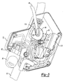
Fig. 3 is a side perspective view of the bail actuation control assembly ofFig. 2 and shown with a portion of the housing removed; -
Fig. 4 is a partial exploded view of components associated with the bail actuation control assembly; -
Fig. 5 is another exploded perspective view of the components shown inFig. 4 ; -
Fig. 6 is a side perspective view of a bail crank, a button crank, and a switch assembly of the bail actuation control assembly shown inFig. 3 and illustrated with the button crank in an offset position relative to a pawl on the bail crank; -
Fig. 7 is a side perspective view of the bail crank, button crank, and switch assembly shown inFig. 6 and illustrated with the button crank in an aligned position with the pawl of the bail crank; -
Fig. 8 is a side perspective view of the bail crank, button crank, and switch assembly shown inFig. 6 and illustrated with the bail crank rotated prior to attempted translation of the button crank; -
Fig. 9 is a side view of the bail crank, button crank and switch assembly and shown with the bail handle in a deactivated position and a switch input member of the switch assembly in an "OFF" position; -
Fig. 10 is a side view of the bail crank, button crank and switch assembly shown inFig. 9 and illustrated with the bail handle being rotated from the deactivated position and toward an activated position; -
Fig. 11 is a side view of the bail crank, button crank and switch assembly and shown with the bail handle rotated to an activated position and with the switch input member rotated to an "ON" position; and -
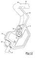
Fig. 12 is a front detailed perspective view of the upright assembly ofFig. 1 and shown with the bail handle moved away from engagement with the bail crank in a shipping position. - With initial reference to
Figs. 1 and2 , an electric outdoor power machine in the form of a battery-powered lawn mower (hereinafter, mower) is shown and generally identified atreference numeral 10. While the following discussion is directed toward a battery-powered lawn mower, the teachings are also applicable to other electric corded or cordless outdoor power machines, such as, but not limited to, tillers, snow throwers, rotary mowers, edgers and power washers. Themower 10 includes a machine body ordeck 12 supported bywheels 14. Thedeck 12 defines abattery pocket 16 on an upper end. Abattery 20 is removably received within thebattery pocket 16. Amotor 22 is selectively powered by thebattery 20 and drives an output member in the form of acutting mechanism 24. Thecutting mechanism 24 can include one or more blades (only one shown) mounted for rotatable motion within thedeck 12. - The
exemplary battery 20 includes abattery housing 30 that can be formed of rigid plastic for example. In one example, thebattery housing 30 can include three battery cells (not specifically shown) that are connected in series, however, other configurations are contemplated. Theexemplary battery 20 can be configured to provide 36 volts direct current (DC). It is appreciated that thebattery 20 can be configured to provide other voltages. Ahandle 32 is formed on an upper end of thebattery housing 30. Alatch assembly 36 is provided on thedeck 12 and includes alatch 38 and alever 40. In general, thelatch 38 and thelever 40 can rotatably cooperate to secure thebattery 20 within thebattery pocket 16 in an installed position (as illustrated inFig. 1 ). Other features of thebattery 20 including its operation and its electrical and mechanical compatibility with the exemplary battery-poweredlawn mower 10 can be found in commonly owned and copendingU.S. Patent Application Serial Number 61/048,002 - The
mower 10 includes an upright assembly or handle 44, a manual input member orbail handle 46, and bailactuation control assembly 50. While the manual input member is shown in the form of a bail handle, it may take other forms such as a lever, a knob or other actuator that is movable by the operator. Theupright assembly 44 generally includes a first and a secondupright member gripping handle 56. Thebail handle 46 generally includes afirst end 58 that rotatably communicates with the bailactuation control assembly 50 and asecond end 60 that is rotatably received in an opening 62 (Fig. 2 ) of the secondupright member 54. As will be described in greater detail, thebail handle 46 is rotatably mounted relative to theupright assembly 44 for rotation along abail axis 66. In one example, the grippinghandle 56 includes a resilient gripping medium 68. The gripping medium 68 can comprise any compliant material such as foam for example. - With continued reference to
Figs. 1 and2 and additional reference now toFig. 3 , the bailactuation control assembly 50 will be described in greater detail. The bailactuation control assembly 50 generally includes aclam shell housing 70 having a firstclam shell portion 72 and a secondclam shell portion 74. The firstclam shell portion 72 includes a rib 75 (Fig. 3 ) that extends in a direction generally transverse to the face of thebutton 76. Abutton 76 is movably supported by thehousing 70 between an unactuated position (generally outward as shown inFig. 2 ) and an actuated position (a depressed position). A key 80 is removably received within akey receiver 82 provided on thehousing 70. - With further reference now to
Figs. 4 and5 , a button crank 84 is coupled to thebutton 76 and axially supported by anaxle 88. As will be described in greater detail herein, the button crank 84 is both rotatable around a button crankaxis 90 defined by theaxle 88 and translatable along theaxle 88. Abutton biasing member 94 urges the button crank 84 and therefore thebutton 76 toward the unactuated position (i.e., outwardly). Aswitch assembly 100 is supported within thehousing 70. Theswitch assembly 100 includes aswitch input member 102. Theswitch input member 102 can comprise any input member, such as a rocker switch as shown in the exemplary embodiment. Theswitch input member 102 is mounted for rotatable motion around a rocker axis 104 (Fig. 6 ). - Turning now to
Figs. 6 and 7 , a bail crank 110 is provided at thefirst end 58 of thebail handle 46. The bail crank 110 generally includes a crankbody 112, atorsion arm 114 and a bail crankpawl 116. Thetorsion arm 114 can define a torsion arm slot 120 (see alsoFig. 4 ) that selectively receives thebail handle 46. The bail handle 46 defines abail post 122 formed generally at a right angle relative to a portion of the bail handle adjacent to thetorsion arm 114. Abail biasing member 124 is journaled around a portion of thecrank body 112. As will be described in more detail herein, thebail handle 46 is rotatable around thebail axis 66 defined through thebail post 122. Thecrank body 112 defines a slot 128 (see alsoFig. 4 ) that receives one end of thebail biasing member 124. The opposite end of thebail biasing member 124 is statically mounted in thehousing 70, such that thebail biasing member 124 biases the bail handle 46 toward a deactivated position (as shown inFig. 1 ) or a position generally offset from thegripping handle 56. - The button crank 84 defines a
crank body 132 having afirst crank arm 134, asecond crank arm 136 and ahub 138. Anaxle passage 140 is defined through thecrank body 132 for receiving theaxle 88. Thefirst crank arm 134 and second crankarm 136 can collectively define aninterface portion 142. Aboss 144 defined in thebutton 76 receives thehub 138 of the button crank 84. - The bail
actuation control assembly 50 according to the present teachings provides a two-motion manual activation system. The bailactuation control assembly 50 allows a user to actuate a two-motion system with the benefits of thebail handle 46. In order to activate the two-motion manual activation system, the user must, in sequence, first depress thebutton 76 from the deactivated position (Figs. 1 and6 ) to the actuated position (Fig. 7 ) followed by rotation of the bail handle 46 from the deactivated position (Fig. 9 ) to the activated position (Fig. 11 ). - With reference now to
Figs. 6-11 , operation of the bailactuation control assembly 50 according to one example will be described. At the outset, a user can depress the button 76 (Fig. 2 ) causing thebutton 76 to urge the button crank 84 axially along theaxle 88 in a direction along the button crankaxis 90. Notably, as shown inFig. 6 , prior to depression of thebutton 76, the button crank 84 is normally biased outwardly (in the unactuated position) by the button biasing member 94 (Fig. 4 ). In the unactuated position (as shown inFig. 6 ), theinterface portion 142 of the button crank 84, or more specifically, thefirst crank arm 134, is laterally offset from the bail crankpawl 116. As a result, thebail handle 46 is free to rotate about the bail post axis 126 defined by the post 122 (or more generally about thebail axis 66,Fig. 2 ) prior to depression of thebutton 76 without making contact with the button crank 84. - As shown in
Fig. 7 , when thebutton 76 is depressed, the button crank 84 is slidably translated along the button crankaxis 90 of theaxle 88 into the actuated position. As shown, in the actuated position, theinterface portion 142, or more specifically thefirst crank arm 134, is now laterally aligned with the bail crankpawl 116 of the bail crank 110. Next, a user can rotate the bail handle 46 from the deactivated position toward the activated position or more specifically in a counterclockwise direction around the bail post axis as viewed inFigs. 9-11 . Rotation of thebail handle 46 will cause the bail crankpawl 116 to rotatably engage thefirst crank arm 134 of the button crank 84 and therefore cause the button crank 84 to rotate in a clockwise direction around theaxle 88 as viewed inFigs. 9-11 . Rotation of the button crank 84 in the clockwise direction around theaxle 88 will cause thesecond crank arm 136 to rotatably engage theswitch input member 102 and cause theswitch input member 102 to rotate in a generally counterclockwise direction around therocker axis 104 as shown inFigs. 9-11 . With theswitch input member 102 rotated to an "ON" position as illustrated inFig. 11 , theswitch 101 communicates power from thebattery 20 to thecutting mechanism 24. As a further safety feature, the key 80 must be placed within the key receiver 82 (to complete an electrical loop) for the bail actuation control assembly to allow power to be delivered to thecutting mechanism 24. - Power cannot be communicated to the
cutting mechanism 24 of the battery-poweredlawn mower 10 by reversing the order of the actions, e.g. rotation of thebail handle 46 followed by depression of thebutton 76. Similarly, movement only of the bail handle 46 from the deactivated position to the activated position will not provide power to the battery-poweredlawn mower 10 nor will only depression of thebutton 76 from the unactuated position to the actuated position. As illustrated in phantom inFig. 8 , if thebail handle 46 is first moved to the activated position, thefirst crank arm 134 is blocked from translating along theaxle 88 by thepawl 116. Also as will be described, once the bailactuation control assembly 50 has been properly activated (thebutton 76 first depressed, followed by rotation of the bail handle 46 to the activated position), the user need not keep thebutton 76 depressed while thebail handle 46 is in the activated position. - When a user releases the
bail handle 46, thebail biasing member 124 will urge the bail handle 46 into the deactivated position (or in a direction generally clockwise as viewed inFigs. 9-11 ). Once the bail crankpawl 116 rotates in the clockwise direction, therocker spring 103 urges theswitch input member 102 in the clockwise direction causing the button crank 84 to rotate in the counterclockwise direction back to a position as shown inFig. 9 . Once the button crank 84 returns to a location as viewed inFig. 9 , the button crank 84 clears the rib 75 (Fig. 3 ) provided in thehousing 70 such that thebutton biasing member 94 urges the button crank 84, and therefore thebutton 76, in a direction generally leftward (as viewed inFig. 3 ) along the button crankaxis 90 of theaxle 88 as viewed inFig. 6 into the unactuated position. When thesecond crank arm 136 is aligned with the rib 75 (i.e., when the button crank 84 is rotated to the position shown inFig. 11 ), therib 75 will block the button crank 84 and therefore thebutton 76 from returning to the unactuated position under the bias of thebutton biasing member 94. As can be appreciated, a user need not keep thebutton 76 depressed during operation. - With reference now to
Fig. 12 , the bail handle 46 can be moved to a shipping position in a location generally against the grippingmember 68. This allows the battery-poweredlawn mower 10 to be shipped without placing stresses on the components of the bailactuation control assembly 50, such as any of the biasing members described herein while the battery-poweredlawn mower 10 is shipped in its packaging. To move the bail handle 46 to the shipping position, as illustrated inFig. 12 , the bail handle 46 can be moved generally rightward as viewed inFig. 12 , such that thefirst end 58 of thebail handle 46 is moved away or disengaged from thetorsion arm slot 120 of thetorsion arm 114 of the bail crank 110. With thefirst end 58 of the bail handle 46 moved laterally away from thetorsion arm slot 120, the bail handle 46 can be moved to a position alongside thegripping handle 56 without moving the bail crank 110 and therefore without moving any of the components associated with the bailactuation control assembly 50. To move the bail handle 46 back toward an operating position, as shown inFig. 1 , thebail handle 46 is rotated away from thegripping handle 56 and directed back into a nesting position within thetorsion arm slot 120 of thetorsion arm 114 provided by the bail crank 110. - While the disclosure has been described in the specification and illustrated in the drawings with reference to various embodiments, it will be understood by those skilled in the art that various changes may be made and equivalents may be substituted for elements thereof without departing from the scope of the disclosure as defined in the claims. For example, while directional indicators such as leftward, rightward, clockwise and counterclockwise have been used herein, various components, such as associated with the bail
actuation control assembly 50, can be configured for movement in other directions while still reaching similar results. Furthermore, the mixing and matching of features, elements and/or functions between various embodiments is expressly contemplated herein so that one of ordinary skill in the art would appreciate from this disclosure that features, elements and/or functions of one embodiment may be incorporated into another embodiment as appropriate, unless described otherwise above. Moreover, many modifications may be made to adapt a particular situation or material to the teachings of the disclosure without departing from the essential scope thereof. Therefore, it is intended that the disclosure not be limited to the particular embodiments illustrated by the drawings and described in the specification as the best mode presently contemplated for carrying out this disclosure, but that the disclosure will include any embodiments falling within the foregoing description and the appended claims.
Claims (12)
- An electric outdoor power machine (10) characterized in that it includes:a machine body (12) supported by wheels (14) and having an output member (24) driven by a motor (22), the motor being powered by a source of electrical power (20);an upright assembly (44) extending from the machine body and having a gripping handle (56);a manual input member (46) adjacent to the gripping handle and movable relative to the gripping handle between a deactivated position and an activated position; anda control assembly (50) that selectively communicates electric power to the output member, the control assembly comprising:a button (76) supported by a housing (70) on the upright assembly, the button movable between an unactuated position and an actuated position;a button crank (84) coupled to the button and having an interface portion (142);a switch (101) having a switch input member (102) movable between an "ON" position and an "OFF" position, wherein in the "ON" position, the switch electrically connects the source of electrical power with the motor; anda pawl (116) extending from the manual input member;
wherein the switch is moved to the "ON" position by sequential movement of the button into the actuated position followed by movement of the manual input member from the deactivated position to the activated position, wherein movement of the button into the actuated position operatively moves the interface portion of the button crank from an offset position relative to the pawl to an aligned position with the pawl such that movement of the manual input member to the activated position causes the pawl to move the interface portion into contact with the switch input member which in turn moves the switch to the "ON" position. - The electric outdoor power machine of claim 1 further characterized in that movement of the button from the unactuated position to the actuated position is precluded subsequent to movement of the manual input member to the activated position.
- The electric outdoor power machine of claim 2 further characterized in that the pawl is operatively aligned with and blocks the interface portion of the button crank from movement when the manual input member is moved to the activated position prior to movement of the button into the actuated position.
- The electric outdoor power machine of any one of the previous claims, further characterized in that the interface portion includes a first crank arm (134) that rotatably engages the pawl and a second crank arm (136) that rotatably engages the switch input member.
- The electric outdoor power machine of claim 4 further characterized in that the switch input member is a rocker switch that rotates about a rocker axis (104) upon engagement from the second crank arm.
- The electric outdoor power machine of any one of the previous claims, further characterized in that the button crank is rotatably mounted about a button crank axle (88) and wherein the button crank slidably advances along the button crank axle (90) toward the aligned position upon movement of the button from the unactuated position to the actuated position.
- The electric outdoor power machine of claim 6 further characterized in that the manual input member comprises a bail handle having an upright post (122) that defines a post axis (66), wherein the bail handle rotates relative to an upright (52, 54) of the upright assembly about the post axis between the deactivated and activated positions.
- The electric outdoor power machine of claim 7 further characterized in that the button crank axle defines a button crank axis (90) that is substantially parallel to the post axis.
- The electric outdoor power machine of any one of the previous claims, further characterized in that it includes a biasing member (94) that biases the manual input member toward the deactivated position.
- The electric outdoor power machine of any one of the previous claims, wherein the control assembly is further characterized in that it includes a key (80) removably positioned within a key receiver (82) defined on the housing, wherein the switch electrically connects the source of electrical power with the motor upon installation of the key into the key receiver.
- A method of operating an electric outdoor power machine (10) having a motor (22) that drives an output member (24), the method characterized in that it includes:actuating a button (76) supported on a housing (70) of an upright assembly (44) on the power machine, the button translating a button crank (84);rotating a manual input member (46) coupled to the upright assembly subsequent to actuating the button from an deactivated position to an activated position, the manual input member having a pawl (116) that operatively engages the button crank and rotates the button crank from a first position to a second position; andwherein rotation of the button crank to the second position causes the button crank to move a switch input member (102) of a switch (101) from an "OFF" position to an "ON" position, wherein in the "ON" position, the switch electrically connects the motor with a source of electrical power.
- The method of claim 11 wherein actuating the button further includes:translating an interface portion (142) of the button crank from an offset position relative to the pawl to an aligned position with the pawl such that rotating the manual input member to the activated position causes the pawl to rotate a first crank arm (134) on the interface portion such that a second crank arm (136) on the interface portion moves into contact with and rotates the switch input member.
Applications Claiming Priority (1)
| Application Number | Priority Date | Filing Date | Title |
|---|---|---|---|
| US12/347,072 US7762049B2 (en) | 2008-12-31 | 2008-12-31 | Electric mower having two-motion activation system |
Publications (1)
| Publication Number | Publication Date |
|---|---|
| EP2204082A1 true EP2204082A1 (en) | 2010-07-07 |
Family
ID=42078920
Family Applications (1)
| Application Number | Title | Priority Date | Filing Date |
|---|---|---|---|
| EP09180693A Withdrawn EP2204082A1 (en) | 2008-12-31 | 2009-12-23 | Electric mower having two-motion activation system |
Country Status (3)
| Country | Link |
|---|---|
| US (1) | US7762049B2 (en) |
| EP (1) | EP2204082A1 (en) |
| CN (1) | CN201898044U (en) |
Cited By (1)
| Publication number | Priority date | Publication date | Assignee | Title |
|---|---|---|---|---|
| EP2534935A1 (en) * | 2011-06-14 | 2012-12-19 | Makita Corporation | Electric lawn mowers |
Families Citing this family (36)
| Publication number | Priority date | Publication date | Assignee | Title |
|---|---|---|---|---|
| US20090266042A1 (en) * | 2008-04-25 | 2009-10-29 | Mooney P Wade | Mower |
| US8429885B2 (en) * | 2008-04-25 | 2013-04-30 | Black & Decker Inc. | Cordless mower including cooling air flow arrangement |
| US8653786B2 (en) * | 2008-04-25 | 2014-02-18 | Black & Decker Inc. | Cordless mower including battery with two charging connectors |
| JP2011079510A (en) * | 2009-09-10 | 2011-04-21 | Makita Corp | Electric vehicle |
| CN102232332B (en) * | 2010-04-21 | 2013-07-03 | 苏州宝时得电动工具有限公司 | Mower |
| DE102010044302B4 (en) * | 2010-09-03 | 2014-12-11 | Al-Ko Kober Ges. M.B.H | Handle for a gardening tool and gardening tool |
| US9241441B2 (en) | 2012-02-22 | 2016-01-26 | Husqvarna Ab | Robotic lawnmower |
| EP2636295B1 (en) | 2012-03-07 | 2014-09-10 | Robert Bosch GmbH | Lawn-care apparatus |
| EP2657950A1 (en) * | 2012-04-24 | 2013-10-30 | Robert Bosch Gmbh | Isolator switch assembly |
| USD676876S1 (en) | 2012-05-25 | 2013-02-26 | The Toro Company | Handle for a ground-working implement |
| US9596806B2 (en) | 2013-10-10 | 2017-03-21 | Chervon (Hk) Limited | Control system for controlling the operation of a gardening tool |
| US11606900B2 (en) | 2012-10-15 | 2023-03-21 | Chervon (Hk) Limited | Gardening tool |
| US9888627B2 (en) | 2012-10-15 | 2018-02-13 | Chervon (Hk) Limited | Lawncare apparatus with a foldable operating arm |
| US9847186B2 (en) | 2013-01-30 | 2017-12-19 | The Toro Company | Starter and power equipment unit incorporating same |
| US9185843B2 (en) | 2013-11-15 | 2015-11-17 | Honda Motor Co., Ltd. | Variable speed control systems and methods for walk behind working machine |
| US9470305B2 (en) | 2014-01-24 | 2016-10-18 | Honda Motor Co., Ltd. | Variable speed control systems and methods for walk-behind working machines |
| CN105432238B (en) * | 2014-08-21 | 2017-06-30 | 南京德朔实业有限公司 | mower and safety device thereof |
| CN104932607B (en) * | 2015-05-26 | 2016-07-13 | 苏州金莱克精密机械有限公司 | A kind of three-level protective for gardens electric tool switchs |
| USD777795S1 (en) | 2015-09-15 | 2017-01-31 | The Toro Company | Handle for a ground working implement |
| CN105325128B (en) * | 2015-11-28 | 2017-06-09 | 宁波市德霖机械有限公司 | The operating mechanism and its hay mover of a kind of hay mover |
| ES2962769T3 (en) * | 2016-06-14 | 2024-03-21 | Globe Jiangsu Co Ltd | power device |
| CN117256299A (en) * | 2017-06-23 | 2023-12-22 | 创科(澳门离岸商业服务)有限公司 | Lawn mower |
| JP7068959B2 (en) * | 2018-08-02 | 2022-05-17 | 株式会社クボタ | Battery connector assembly and battery equipment |
| CN109392467B (en) | 2018-12-14 | 2024-01-02 | 格力博(江苏)股份有限公司 | Garden Tools |
| CN110700060B (en) * | 2019-09-23 | 2024-03-26 | 金华市亚虎工具有限公司 | Floor cutting machine |
| US20210112710A1 (en) * | 2019-10-18 | 2021-04-22 | Bluebird Turf Products LLLP, A Delaware Limited Liability Partnership | Electric Power Hover Lawn Mower |
| US11129238B1 (en) * | 2020-01-02 | 2021-09-21 | Gary D. Riha | Battery powered wireless controller system |
| US11638397B2 (en) | 2020-02-10 | 2023-05-02 | Techtronic Cordless Gp | Control assembly coupled to handle of an implement |
| US12069984B2 (en) * | 2021-09-29 | 2024-08-27 | The Toro Company | Walk outdoor power equipment unit having handle mounted operational controls using compliant mechanisms |
| CN113841470A (en) * | 2021-10-12 | 2021-12-28 | 宁波爱乐吉电动工具股份有限公司 | a raking machine |
| US12576746B2 (en) * | 2021-10-14 | 2026-03-17 | Briggs & Stratton, Llc | Lawn tractor with removable battery packs |
| US12279552B2 (en) | 2021-12-08 | 2025-04-22 | Honda Motor Co., Ltd. | Blade control assembly, lawnmower, and method for operating a blade control assembly |
| US20230397528A1 (en) * | 2022-06-13 | 2023-12-14 | Milwaukee Electric Tool Corporation | Power tool user interface |
| US12527252B2 (en) | 2022-10-31 | 2026-01-20 | Honda Motor Co., Ltd. | Blade control system and lawnmower |
| CN116784088A (en) * | 2023-07-19 | 2023-09-22 | 宁波动创机电有限公司 | A weeding machine with adjustable weeding height |
| WO2025237281A1 (en) * | 2024-05-15 | 2025-11-20 | 格力博(江苏)股份有限公司 | Push mower and control method therefor |
Citations (5)
| Publication number | Priority date | Publication date | Assignee | Title |
|---|---|---|---|---|
| US3982082A (en) * | 1975-08-04 | 1976-09-21 | The Toro Company | Starting system |
| US4800208A (en) | 1986-08-13 | 1989-01-24 | A. Menarini S.A.S. | (Benzofuran-2-yl)imidazoles having pharmaceutical activity, their salts and relevant production processes |
| US5203147A (en) * | 1992-01-22 | 1993-04-20 | Ryobi Motor Products Corp. | Lawn mower activation switch |
| WO1996005719A2 (en) * | 1994-08-22 | 1996-02-29 | Briggs & Stratton Corporation | Improved battery-powered lawn cutting system |
| US6078015A (en) * | 1998-01-22 | 2000-06-20 | Mtd Products Inc | Actuator for power switch in a lawn and garden care appliance |
Family Cites Families (28)
| Publication number | Priority date | Publication date | Assignee | Title |
|---|---|---|---|---|
| US4309862A (en) * | 1980-06-09 | 1982-01-12 | Capro, Inc. | Lawn mower and controls therefor |
| US4430848A (en) * | 1981-09-28 | 1984-02-14 | Mcdonough Power Equipment, Division Of Fuqua Industries, Inc. | Double action manual control for walk-behind mower |
| US4413466A (en) * | 1982-01-01 | 1983-11-08 | Conchemco, Incorporated | Control assembly for blade clutch unit |
| JPS58205416A (en) * | 1982-05-25 | 1983-11-30 | スタ−テング工業株式会社 | Operation lever for mower |
| US4466308A (en) * | 1982-06-16 | 1984-08-21 | Conchemco, Incorporated | Control assembly for lawnmower having electrically started engine |
| US4667459A (en) * | 1985-03-14 | 1987-05-26 | Roper Corporation | Two action control for power mowers |
| US4753062A (en) * | 1987-06-11 | 1988-06-28 | Capro, Inc. | Lawn mower and safety control therefor |
| US4833935A (en) * | 1987-06-11 | 1989-05-30 | Capro, Inc. | Lawn mower electric start control |
| US4930369A (en) * | 1987-07-09 | 1990-06-05 | Wescon Products Company | Radial ground drive and blade clutch control for lawnmower |
| US4967543A (en) * | 1989-10-10 | 1990-11-06 | Scag Power Equipment, Inc. | Lawn mower |
| US5085043A (en) * | 1990-06-01 | 1992-02-04 | Black & Decker Inc. | Electro-mechanical interlock and module system for lawn mower or other electrical device |
| US5279101A (en) * | 1992-06-25 | 1994-01-18 | Honda Giken Kogyo Kabushiki Kaisha | Control lever assembly for self-propelled machinery |
| EP0817352A2 (en) * | 1992-08-18 | 1998-01-07 | Black & Decker Inc. | Improvements in battery operated electric machines |
| US5375674A (en) * | 1993-04-13 | 1994-12-27 | Mtd Products Inc. | Operator control for lawn and garden vehicles |
| US5606851A (en) * | 1993-09-22 | 1997-03-04 | Briggs & Stratton Corporation | Battery-powered lawn cutting system |
| US5937622A (en) * | 1995-07-26 | 1999-08-17 | Black & Decker Inc. | Cordless electric lawn mower having energy management control system |
| JP3329654B2 (en) * | 1996-03-22 | 2002-09-30 | 株式会社マキタ | Operation switch of electric lawn mower |
| US5784868A (en) * | 1996-06-13 | 1998-07-28 | The Toro Company | Control system for outdoor power equipment |
| GB2338392A (en) * | 1998-06-16 | 1999-12-22 | Black & Decker Inc | Switch for battery powered lawn mower. |
| US6230678B1 (en) * | 1998-10-30 | 2001-05-15 | Briggs & Stratton Corporation | Starting and stopping device for internal combustion engine |
| EP1333712B1 (en) * | 2000-10-20 | 2006-06-07 | MTD Products Inc. | Apparatus and method for starting a mower engine |
| JP4607382B2 (en) * | 2000-12-28 | 2011-01-05 | 本田技研工業株式会社 | Walking type work machine |
| JP2002315416A (en) * | 2001-04-20 | 2002-10-29 | Honda Motor Co Ltd | Walking type self-propelled work machine |
| US6668529B2 (en) * | 2001-06-27 | 2003-12-30 | Emark Manufacturing Company, Incorporated | Operator control system for self-propelled vehicles |
| JP3776772B2 (en) * | 2001-08-22 | 2006-05-17 | 本田技研工業株式会社 | Electric lawn mower |
| US7540131B2 (en) * | 2004-09-16 | 2009-06-02 | The Toro Company | Ground speed control system with hill assist, cruise control and lockout lever |
| US7712292B2 (en) * | 2005-11-09 | 2010-05-11 | The Toro Company | Control system for outdoor power equipment |
| US7543430B2 (en) * | 2007-09-10 | 2009-06-09 | Honda Motor Co., Ltd. | Button type blade brake clutch control |
-
2008
- 2008-12-31 US US12/347,072 patent/US7762049B2/en not_active Expired - Fee Related
-
2009
- 2009-12-23 EP EP09180693A patent/EP2204082A1/en not_active Withdrawn
- 2009-12-23 CN CN2009202992595U patent/CN201898044U/en not_active Expired - Fee Related
Patent Citations (5)
| Publication number | Priority date | Publication date | Assignee | Title |
|---|---|---|---|---|
| US3982082A (en) * | 1975-08-04 | 1976-09-21 | The Toro Company | Starting system |
| US4800208A (en) | 1986-08-13 | 1989-01-24 | A. Menarini S.A.S. | (Benzofuran-2-yl)imidazoles having pharmaceutical activity, their salts and relevant production processes |
| US5203147A (en) * | 1992-01-22 | 1993-04-20 | Ryobi Motor Products Corp. | Lawn mower activation switch |
| WO1996005719A2 (en) * | 1994-08-22 | 1996-02-29 | Briggs & Stratton Corporation | Improved battery-powered lawn cutting system |
| US6078015A (en) * | 1998-01-22 | 2000-06-20 | Mtd Products Inc | Actuator for power switch in a lawn and garden care appliance |
Cited By (1)
| Publication number | Priority date | Publication date | Assignee | Title |
|---|---|---|---|---|
| EP2534935A1 (en) * | 2011-06-14 | 2012-12-19 | Makita Corporation | Electric lawn mowers |
Also Published As
| Publication number | Publication date |
|---|---|
| US20100162674A1 (en) | 2010-07-01 |
| CN201898044U (en) | 2011-07-13 |
| US7762049B2 (en) | 2010-07-27 |
Similar Documents
| Publication | Publication Date | Title |
|---|---|---|
| US7762049B2 (en) | Electric mower having two-motion activation system | |
| EP2606717B1 (en) | Vegetation cutting device | |
| EP1762136B2 (en) | Power tool with interchangeable blades and method | |
| US3873796A (en) | Trigger mechanism for hand-operated power device including independently operable locking devices providing automatic lock off and manual lock-on operation | |
| US3847233A (en) | Trigger mechanism for hand-operated power device providing automatic lock-off and manual lock-on operation | |
| CN102781222B (en) | Power tool | |
| EP2233251B1 (en) | Impact tool | |
| US4122320A (en) | Hand-operated double-acting trigger switch | |
| US9242362B2 (en) | Slide switch for a power tool | |
| CN101658105B (en) | Switch-operating mechanism | |
| US6973728B2 (en) | Filament trimmer with dual triggers | |
| EP3669628B1 (en) | Garden tool and control box thereof | |
| US6610946B2 (en) | Actuation mechanism for a power tool | |
| JPH08205676A (en) | Operating lever mechanism for handle | |
| EP2622953B1 (en) | Electric cultivators | |
| US20120055032A1 (en) | Hedge trimmer | |
| JP4615850B2 (en) | Power working machine | |
| US7213340B1 (en) | Battery-operated can opener | |
| CN110125882B (en) | Switch device for electrically driven garden tool | |
| JP2005160306A (en) | Power working machine | |
| JPH06262414A (en) | Motor-driven tool | |
| EP1787507B1 (en) | Power tool | |
| CN109243882B (en) | Switch box device and power tool | |
| JP4455112B2 (en) | Power working machine | |
| CN121282040A (en) | Machine tools and their switching units |
Legal Events
| Date | Code | Title | Description |
|---|---|---|---|
| PUAI | Public reference made under article 153(3) epc to a published international application that has entered the european phase |
Free format text: ORIGINAL CODE: 0009012 |
|
| AK | Designated contracting states |
Kind code of ref document: A1 Designated state(s): AT BE BG CH CY CZ DE DK EE ES FI FR GB GR HR HU IE IS IT LI LT LU LV MC MK MT NL NO PL PT RO SE SI SK SM TR |
|
| AX | Request for extension of the european patent |
Extension state: AL BA RS |
|
| 17P | Request for examination filed |
Effective date: 20100715 |
|
| STAA | Information on the status of an ep patent application or granted ep patent |
Free format text: STATUS: THE APPLICATION IS DEEMED TO BE WITHDRAWN |
|
| 18D | Application deemed to be withdrawn |
Effective date: 20110108 |