EP2203722B1 - Integrally formed receptacle with depth marks on the sidewall - Google Patents
Integrally formed receptacle with depth marks on the sidewall Download PDFInfo
- Publication number
- EP2203722B1 EP2203722B1 EP08806669.1A EP08806669A EP2203722B1 EP 2203722 B1 EP2203722 B1 EP 2203722B1 EP 08806669 A EP08806669 A EP 08806669A EP 2203722 B1 EP2203722 B1 EP 2203722B1
- Authority
- EP
- European Patent Office
- Prior art keywords
- sidewall
- jug
- base wall
- upper edge
- receptacle
- Prior art date
- Legal status (The legal status is an assumption and is not a legal conclusion. Google has not performed a legal analysis and makes no representation as to the accuracy of the status listed.)
- Active
Links
Images




Classifications
-
- A—HUMAN NECESSITIES
- A47—FURNITURE; DOMESTIC ARTICLES OR APPLIANCES; COFFEE MILLS; SPICE MILLS; SUCTION CLEANERS IN GENERAL
- A47G—HOUSEHOLD OR TABLE EQUIPMENT
- A47G19/00—Table service
- A47G19/12—Vessels or pots for table use
-
- G—PHYSICS
- G01—MEASURING; TESTING
- G01F—MEASURING VOLUME, VOLUME FLOW, MASS FLOW OR LIQUID LEVEL; METERING BY VOLUME
- G01F19/00—Calibrated capacity measures for fluids or fluent solid material, e.g. measuring cups
-
- A—HUMAN NECESSITIES
- A47—FURNITURE; DOMESTIC ARTICLES OR APPLIANCES; COFFEE MILLS; SPICE MILLS; SUCTION CLEANERS IN GENERAL
- A47K—SANITARY EQUIPMENT; ACCESSORIES THEREFOR, e.g. TOILET ACCESSORIES
- A47K1/00—Wash-stands; Appurtenances therefor
- A47K1/04—Basins; Jugs; Holding devices therefor
-
- B—PERFORMING OPERATIONS; TRANSPORTING
- B65—CONVEYING; PACKING; STORING; HANDLING THIN OR FILAMENTARY MATERIAL
- B65D—CONTAINERS FOR STORAGE OR TRANSPORT OF ARTICLES OR MATERIALS, e.g. BAGS, BARRELS, BOTTLES, BOXES, CANS, CARTONS, CRATES, DRUMS, JARS, TANKS, HOPPERS, FORWARDING CONTAINERS; ACCESSORIES, CLOSURES, OR FITTINGS THEREFOR; PACKAGING ELEMENTS; PACKAGES
- B65D1/00—Rigid or semi-rigid containers having bodies formed in one piece, e.g. by casting metallic material, by moulding plastics, by blowing vitreous material, by throwing ceramic material, by moulding pulped fibrous material or by deep-drawing operations performed on sheet material
- B65D1/40—Details of walls
-
- B—PERFORMING OPERATIONS; TRANSPORTING
- B65—CONVEYING; PACKING; STORING; HANDLING THIN OR FILAMENTARY MATERIAL
- B65D—CONTAINERS FOR STORAGE OR TRANSPORT OF ARTICLES OR MATERIALS, e.g. BAGS, BARRELS, BOTTLES, BOXES, CANS, CARTONS, CRATES, DRUMS, JARS, TANKS, HOPPERS, FORWARDING CONTAINERS; ACCESSORIES, CLOSURES, OR FITTINGS THEREFOR; PACKAGING ELEMENTS; PACKAGES
- B65D1/00—Rigid or semi-rigid containers having bodies formed in one piece, e.g. by casting metallic material, by moulding plastics, by blowing vitreous material, by throwing ceramic material, by moulding pulped fibrous material or by deep-drawing operations performed on sheet material
- B65D1/40—Details of walls
- B65D1/42—Reinforcing or strengthening parts or members
-
- B—PERFORMING OPERATIONS; TRANSPORTING
- B65—CONVEYING; PACKING; STORING; HANDLING THIN OR FILAMENTARY MATERIAL
- B65D—CONTAINERS FOR STORAGE OR TRANSPORT OF ARTICLES OR MATERIALS, e.g. BAGS, BARRELS, BOTTLES, BOXES, CANS, CARTONS, CRATES, DRUMS, JARS, TANKS, HOPPERS, FORWARDING CONTAINERS; ACCESSORIES, CLOSURES, OR FITTINGS THEREFOR; PACKAGING ELEMENTS; PACKAGES
- B65D25/00—Details of other kinds or types of rigid or semi-rigid containers
- B65D25/28—Handles
-
- B—PERFORMING OPERATIONS; TRANSPORTING
- B65—CONVEYING; PACKING; STORING; HANDLING THIN OR FILAMENTARY MATERIAL
- B65D—CONTAINERS FOR STORAGE OR TRANSPORT OF ARTICLES OR MATERIALS, e.g. BAGS, BARRELS, BOTTLES, BOXES, CANS, CARTONS, CRATES, DRUMS, JARS, TANKS, HOPPERS, FORWARDING CONTAINERS; ACCESSORIES, CLOSURES, OR FITTINGS THEREFOR; PACKAGING ELEMENTS; PACKAGES
- B65D25/00—Details of other kinds or types of rigid or semi-rigid containers
- B65D25/38—Devices for discharging contents
- B65D25/40—Nozzles or spouts
- B65D25/42—Integral or attached nozzles or spouts
-
- B—PERFORMING OPERATIONS; TRANSPORTING
- B65—CONVEYING; PACKING; STORING; HANDLING THIN OR FILAMENTARY MATERIAL
- B65D—CONTAINERS FOR STORAGE OR TRANSPORT OF ARTICLES OR MATERIALS, e.g. BAGS, BARRELS, BOTTLES, BOXES, CANS, CARTONS, CRATES, DRUMS, JARS, TANKS, HOPPERS, FORWARDING CONTAINERS; ACCESSORIES, CLOSURES, OR FITTINGS THEREFOR; PACKAGING ELEMENTS; PACKAGES
- B65D2203/00—Decoration means, markings, information elements, contents indicators
- B65D2203/04—Level indicators
Definitions
- This invention relates to moulded paper pulp jugs.
- Disposable, paper pulp receptacles are widely used in hospitals, care homes and the like, where it is desirable, for hygiene reasons, and to minimise the risk of cross-infection, to have single-use receptacles.
- moulded paper pulp disposable receptacles can be macerated on-site after use for immediate disposal into a drain or sewer.
- a moulded paper pulp receptacle is a moulded paper pulp jug.
- moulded paper pulp receptacles suffer a number of disadvantages compared to reusable receptacles, namely:
- This invention aims to provide a solution to one or more of the above problems. Additionally or alternatively, this invention aims to provide an improved receptacle.
- US 2 135 045 discloses a calibrated self-supporting sanitary spoon comprising a calibrated bowl portion and a handle portion extending arcuately upwardly and away from the bowl.
- a moulded paper pulp jug comprising a flat or substantially flat base wall and a sidewall extending upwardly from the base wall to define a liquid receiving volume, the sidewall being shaped to form a grip portion having first and second opposed finger-receiving recessed portions and a pouring spout on the opposite side of the jug from the grip portion, the sidewall further comprising a plurality of integrally-formed projections and/or indentations arranged to indicate, in use, the depth of liquid within the liquid receiving volume wherein each of the said opposed recesses in the sidewall comprises a gripping surface comprising a concavity in the exterior of the sidewall which forms a projection projecting into the liquid receiving volume and comprising a shoulder portion at its upper end and wherein the grip portion comprises a base wall located above the level of the jug base wall, and comprises a tapered side wall.
- the plurality of integrally-formed projections and/or indentations may together form a graduated scale for estimating or measuring, in use, the volume of liquid within the liquid receiving volume of the receptacle. Since the scale is integrally formed with the sidewall, it is not possible to incorrectly position or orient the scale (as can be done with a known dipstick). Thus, provided the receptacle is always placed in a known orientation, e.g. on a flat surface, the quantity of liquid within the liquid retaining volume can be more accurately estimated/measured.
- the level of the liquid within the liquid retaining volume of the receptacle is read off against a series of integrally-formed projections/indentations, there is no need to provide a printed scale on the inner surface of the receptacle, which printing constitutes, in any event, an additional manufacturing step, and which printed scale is difficult to register consistently with respect to a datum of the receptacle.
- the indentions/projections may comprise dots and/or dashes and/or other indicia, e.g. letters and/or numerals.
- the indentions/projections can comprise a series of spaced-apart major dashes and one or more minor dashes located between respective pairs of spaced-apart major dashes, and numerals indicating the volume of liquid in the receptacle corresponding to each of the major dashes and/or minor dashes or dots.
- a receptacle comprising a flat or substantially flat base wall, a sidewall extending upwardly from the base wall to define a liquid receiving volume, the upper edge of the sidewall defining the periphery of an opening located above the base wall, wherein the sidewall comprises a spout comprising a generattyv-shaped channel that intersects, and extends downwardly from, the upper edge of the sidewall towards the base wall, and wherein the upper edge of the sidewall is overturned, except in the region of thespout
- the upper edge of the sidewall is preferably overturned, except in the region of the tip of the spout.
- the majority of the upper edge of the sidewall may lie in a first, substantially flat plane, and the upper edge of the sidewall in the vicinity of the spout may lie in a second plane inclined with respect to the first plane.
- the second plane is preferably substantially flat.
- the radius of curvature of the overturned upper edge of the sidewall may be smaller in the vicinity of the spout than around the remainder of the receptacle.
- the upper edge of the sidewall in the vicinity of the spout may have a sharper edge than the upper edge of the sidewall around the remainder of the receptacle.
- the upper edge of the sidewall at the tip of the spout may have a sharper edge than the upper edge of the sidewall around the remainder of the receptacle.
- the v-shaped channel may comprise a pair of substantially triangular, planar surfaces that meet along a valley line, the internal radius of curvature of the valley being less than 5mm.
- the internal radius of curvature of the valley is preferably less than 2mm.
- the upper edge of the sidewall is formed as an integral part of the sidewall.
- the spout is formed integrally with the sidewall.
- a receptacle comprising a flat or substantially flat base wall, a sidewall extending upwardly from the base wall to define a liquid receiving volume, the upper edge of the sidewall defining the periphery of an opening located above the base wall, wherein the sidewall comprises a pair of opposed recesses which form a grip means for grasping the receptacle, each of the said recesses comprising a gripping surface comprising a concavity in the exterior of the sidewall which forms a projection projecting into the liquid receiving volume and comprising a shoulder portion at its upper end.
- the shoulder portion may comprise a substantially planarwall portion.
- the substantially planar wall portions may be substantially parallel to the base wall.
- the substantially planar wall portions are preferably substantially flat.
- the substantially planar wall portions are arranged, in use, to abut the user's thumb and forefinger, whilst the remaining fingers of the user's hand grasp the gripping surfaces.
- Such a configuration provides an amount of triangulation, which enables the receptacle to be more securely gripped, thereby facilitating manipulation thereof.
- a stiffening shoulder may also be provided in the vicinity of the grip means.
- the stiffening shoulder may comprise a surface that projects into the liquid receiving volume of the receptacle.
- the inwardly projecting surface of the stiffening shoulder may extend around a portion of the receptacle corresponding substantially to the position of the grip portion.
- the stiffening shoulder may be located between the rim of the receptacle and the shoulder of the grip portion.
- the stiffening shoulder and/or the shoulders both cause the surface of the receptacle to change direction, which can increase the stiffness of the receptacle in the region of the grip portion.
- increased stiffness can reduce the likelihood of the receptacle being deformed during use, thereby enabling it to be gripped more securely and/or manipulated more easily.
- the stiffening shoulder is preferably located between the grip means and the upper edge of the sidewall.
- the receptacle may further comprise a pouring spout.
- pouring spout and grip means are on opposite sides of the base wall.
- a receptacle comprising a flat or substantially flat base wall, a sidewall extending upwardly from the base wall to define a liquid receiving volume, the upper edge of the sidewall defining the periphery of an opening located above the base wall, a grip means and a stiffening shoulder in the vicinity of the grip means.
- the grip means may comprise a gripping surface comprising a concavity in the exterior of the sidewall which forms a projection projecting into the liquid receiving volume and a shoulder portion at its upper end.
- the grip means may comprise two opposed concavities in the exterior of the sidewall which forms projections projecting into the liquid receiving volume, the opposed concavities being adapted for gripping by the opposed thumb and fingers respectively of a user.
- the stiffening shoulder may comprise a surface that projects into the liquid receiving volume of the receptacle, which inwardly projecting surface of the stiffening shoulder may extend around a portion of the receptacle corresponding substantially to the position of the grip portion.
- the stiffening shoulder is located between the upper edge of the sidewall and the grip means.
- the stiffening shoulder is preferably located between the upper edge of the sidewall and the shoulder portion of the grip portion.
- the receptacle may comprise a pouring spout.
- pouring spout and the grip means are on opposite sides of the base wall.
- a receptacle comprising a flat or substantially flat base wall, a sidewall extending upwardly from the base wall to define a liquid receiving volume, an overturned upper edge of the sidewall defining a periphery of an opening located above the base wall, wherein the radius of curvature of the overturned upper edge of the sidewall is less than ten millimetres.
- the radius of curvature of the overturned upper edge of the sidewall is preferably less than 5mm.
- this configuration may give rise to a higher rim stiffness compared to an equivalent amount of material used in a rim having a greater radius of curvature.
- the smaller the radius of curvature of the rim the greater the rim stiffness for a given amount of material.
- the radius of curvature of the rim is smaller than in known receptacles, the surface area of the rim of the receptacle is reduced, giving rise to a reduction in material usage.
- the receptacle may be manufactured of paper pulp.
- the wall thickness of the paper pulp can be between 1mm and 2mm.
- the opening preferably communicates directly with the liquid receiving volume.
- the receptacle may be a jug.
- a jug 10 manufactured from moulded paper pulp comprises an upwardly open hollow receptacle having a main liquid-receiving portion 12, which communicates with a grip portion 14.
- the main liquid-receiving portion 12 comprises a flat, generally circular base wall 16 and a sidewall 18 extending upwardly from the base wall 16.
- the sidewall 18 tapers inwardly from its upper edge 20 towards the base wall 16 and the upper edge of the sidewall 18 is formed into an overturned lip 22.
- the lip 22 is formed into a pouring spout 24 at a position on the opposite side of the base wall from the grip portion 14.
- the grip portion 14 comprises a generally flat base wall portion 26 which is located above the level of the base wall 16 of the main liquid-receiving portion 12, and a tapered sidewall 28, which extends upwardly from the base wall 26 and merges smoothly with the sidewall 18 of the main liquid-receiving portion 12.
- the upper edge of the sidewall 28 is formed into an overturned lip 30, which merges smoothly with the lip 22 of the main liquid-receiving portion 12.
- the sidewall 28 of the grip portion 14 is formed into two opposed finger recesses 32 on opposite sides of the grip portion 14, which project into the interior of the jug 10.
- the upper end of each of the finger recesses 32 is defined by a generally planar face 34, which forms a shoulder in the interior of the jug 10. The recesses allow the user's hand to grip the grip portion 14.
- the jug 10 is moulded from paper pulp as a single unitary item and all of the features of the jug including the base wall 16, overturned lip 22, spout 24, grip portion 14, overturned lip 30, etc. are formed integrally with each other.
- a user's hand grips the grip portion 14 such that his/her thumb and forefinger simultaneously engage opposite finger recesses 32 and shoulders 34.
- the user's three remaining fingers engage one of the finger recesses 32 at points located below the height of the shoulders 34, and a convex portion 36 of the grip 14 engages the user's palm.
- a stiffening shoulder 38 located at a level between the lip 30 of the jug 10 and the shoulders 34 serves to stiffen the jug 10 in the vicinity of the grip portion 14.
- the stiffening shoulder 38 comprises a radiused edge 40 and a generally flat, u-shaped shelf portion 42 (when viewed from above) that extends around the rear half of the jug 10.
- the shelf portion 42 is widest at the rear of the jug 10 where it aligns with the convex portion 36 of the grip 14, and tapers at either end to blend into the sidewalls 18 of the jug 10 at a point located above the circular base wall 16 thereof.
- the rim 22, 30 of the jug 10 comprises an outwardly directed flange 44 and an overturned peripheral lip portion 46.
- the overturned peripheral lip portion 46 has a small internal radius of curvature, which radius is approximately 2mm.
- the majority of the lip 22, 30 of the jug 10 lies in a first generally flat plane 50.
- the lip 22 lies in a second, flat plane 52 inclined with respect to the first plane 50.
- the lip 22 comprises an outwardly directed flange portion 44, but has no overturned portion.
- the spout 24 comprises a pair of generally flat, triangular wall portions/surfaces 54 whose edges meet along a valley line 56 to form a generally v-section channel that intersects, and extends downwardly from, the lip 22 of the jug 10 towards the base wall 16.
- the v-section channel guides liquid within the liquid receiving volume 12, 14 to the tip of the spout 24 during pouring.
- the internal surface of the sidewall 18 is provided with a scale 58 for indicating the quantity of liquid (not shown) within the liquid receiving volume 12.
- the scale 58 is comprised of integrally moulded indentions in the sidewall 18 that form the major and minor graduations of the scale 58. Numbers and letters are also integrally formed in the sidewall 18 of the jug 10 to facilitate reading the scale 58.
- the pouring spout 24 and the grip portion 14 lie on a plane passing perpendicularly through the base wall 16, about which the lug is symmetrical (apart from the scale 58).
Landscapes
- Engineering & Computer Science (AREA)
- Mechanical Engineering (AREA)
- Physics & Mathematics (AREA)
- Fluid Mechanics (AREA)
- General Physics & Mathematics (AREA)
- Ceramic Engineering (AREA)
- Health & Medical Sciences (AREA)
- Public Health (AREA)
- Details Of Rigid Or Semi-Rigid Containers (AREA)
- Table Devices Or Equipment (AREA)
Description
- This invention relates to moulded paper pulp jugs.
- Disposable, paper pulp receptacles are widely used in hospitals, care homes and the like, where it is desirable, for hygiene reasons, and to minimise the risk of cross-infection, to have single-use receptacles. Conveniently, moulded paper pulp disposable receptacles can be macerated on-site after use for immediate disposal into a drain or sewer. One example of a moulded paper pulp receptacle is a moulded paper pulp jug.
- Whilst functionally adequate, known moulded paper pulp receptacles suffer a number of disadvantages compared to reusable receptacles, namely:
- It is difficult to estimate the volume of liquid within the receptacle, and the known solution of providing a graduated dipstick provides only a subjective, and/or inaccurate estimate of the receptacle's contents.
- Due to the nature of the manufacturing process, known single-use receptacles generally have a rudimentary spout that affords poor control of liquid during pouring.
- Known single use receptacles can be difficult to handle/manipulate, especially where the user wears gloves.
- Being manufactured of moulded paper pulp, known single-use receptacles can have a flimsy feel, and/or can be prone to deformation whilst being gripped.
- This invention aims to provide a solution to one or more of the above problems. Additionally or alternatively, this invention aims to provide an improved receptacle.
- Reference is also made to
US 2 135 045 , which discloses a calibrated self-supporting sanitary spoon comprising a calibrated bowl portion and a handle portion extending arcuately upwardly and away from the bowl. - According to the invention, there is provided a moulded paper pulp jug comprising a flat or substantially flat base wall and a sidewall extending upwardly from the base wall to define a liquid receiving volume, the sidewall being shaped to form a grip portion having first and second opposed finger-receiving recessed portions and a pouring spout on the opposite side of the jug from the grip portion, the sidewall further comprising a plurality of integrally-formed projections and/or indentations arranged to indicate, in use, the depth of liquid within the liquid receiving volume wherein each of the said opposed recesses in the sidewall comprises a gripping surface comprising a concavity in the exterior of the sidewall which forms a projection projecting into the liquid receiving volume and comprising a shoulder portion at its upper end and wherein the grip portion comprises a base wall located above the level of the jug base wall, and comprises a tapered side wall.
- The plurality of integrally-formed projections and/or indentations may together form a graduated scale for estimating or measuring, in use, the volume of liquid within the liquid receiving volume of the receptacle. Since the scale is integrally formed with the sidewall, it is not possible to incorrectly position or orient the scale (as can be done with a known dipstick). Thus, provided the receptacle is always placed in a known orientation, e.g. on a flat surface, the quantity of liquid within the liquid retaining volume can be more accurately estimated/measured.
- Advantageously also, since the level of the liquid within the liquid retaining volume of the receptacle is read off against a series of integrally-formed projections/indentations, there is no need to provide a printed scale on the inner surface of the receptacle, which printing constitutes, in any event, an additional manufacturing step, and which printed scale is difficult to register consistently with respect to a datum of the receptacle.
- The indentions/projections may comprise dots and/or dashes and/or other indicia, e.g. letters and/or numerals. Advantageously, the indentions/projections can comprise a series of spaced-apart major dashes and one or more minor dashes located between respective pairs of spaced-apart major dashes, and numerals indicating the volume of liquid in the receptacle corresponding to each of the major dashes and/or minor dashes or dots.
- Also disclosed, but not forming part of the invention, is a receptacle comprising a flat or substantially flat base wall, a sidewall extending upwardly from the base wall to define a liquid receiving volume, the upper edge of the sidewall defining the periphery of an opening located above the base wall, wherein the sidewall comprises a spout comprising a generattyv-shaped channel that intersects, and extends downwardly from, the upper edge of the sidewall towards the base wall, and wherein the upper edge of the sidewall is overturned, except in the region of thespout
- The upper edge of the sidewall is preferably overturned, except in the region of the tip of the spout. The majority of the upper edge of the sidewall may lie in a first, substantially flat plane, and the upper edge of the sidewall in the vicinity of the spout may lie in a second plane inclined with respect to the first plane. The second plane is preferably substantially flat.
- The radius of curvature of the overturned upper edge of the sidewall may be smaller in the vicinity of the spout than around the remainder of the receptacle. The upper edge of the sidewall in the vicinity of the spout may have a sharper edge than the upper edge of the sidewall around the remainder of the receptacle.
- The upper edge of the sidewall at the tip of the spout may have a sharper edge than the upper edge of the sidewall around the remainder of the receptacle.
- The v-shaped channel may comprise a pair of substantially triangular, planar surfaces that meet along a valley line, the internal radius of curvature of the valley being less than 5mm. The internal radius of curvature of the valley is preferably less than 2mm.
- The above spout configuration affords better control of the liquid during pouring, since the liquid pours over the rim of the receptacle at a more precisely defined position compared to known disposable receptacles.
- Preferably, the upper edge of the sidewall is formed as an integral part of the sidewall.
- Preferably, the spout is formed integrally with the sidewall.
- Also disclosed, but not forming part of the invention, is a receptacle comprising a flat or substantially flat base wall, a sidewall extending upwardly from the base wall to define a liquid receiving volume, the upper edge of the sidewall defining the periphery of an opening located above the base wall, wherein the sidewall comprises a pair of opposed recesses which form a grip means for grasping the receptacle, each of the said recesses comprising a gripping surface comprising a concavity in the exterior of the sidewall which forms a projection projecting into the liquid receiving volume and comprising a shoulder portion at its upper end.
- The shoulder portion may comprise a substantially planarwall portion.
- The substantially planar wall portions may be substantially parallel to the base wall. The substantially planar wall portions are preferably substantially flat.
- The substantially planar wall portions are arranged, in use, to abut the user's thumb and forefinger, whilst the remaining fingers of the user's hand grasp the gripping surfaces. Such a configuration provides an amount of triangulation, which enables the receptacle to be more securely gripped, thereby facilitating manipulation thereof.
- A stiffening shoulder may also be provided in the vicinity of the grip means. Where provided, the stiffening shoulder may comprise a surface that projects into the liquid receiving volume of the receptacle. The inwardly projecting surface of the stiffening shoulder may extend around a portion of the receptacle corresponding substantially to the position of the grip portion. The stiffening shoulder may be located between the rim of the receptacle and the shoulder of the grip portion.
- The stiffening shoulder and/or the shoulders both cause the surface of the receptacle to change direction, which can increase the stiffness of the receptacle in the region of the grip portion. Advantageously, increased stiffness can reduce the likelihood of the receptacle being deformed during use, thereby enabling it to be gripped more securely and/or manipulated more easily.
- The stiffening shoulder is preferably located between the grip means and the upper edge of the sidewall.
- The receptacle may further comprise a pouring spout.
- Preferably the pouring spout and grip means are on opposite sides of the base wall.
- Also disclosed, but not forming part of the invention, is a receptacle comprising a flat or substantially flat base wall, a sidewall extending upwardly from the base wall to define a liquid receiving volume, the upper edge of the sidewall defining the periphery of an opening located above the base wall, a grip means and a stiffening shoulder in the vicinity of the grip means.
- The grip means may comprise a gripping surface comprising a concavity in the exterior of the sidewall which forms a projection projecting into the liquid receiving volume and a shoulder portion at its upper end.
- The grip means may comprise two opposed concavities in the exterior of the sidewall which forms projections projecting into the liquid receiving volume, the opposed concavities being adapted for gripping by the opposed thumb and fingers respectively of a user.
- The stiffening shoulder may comprise a surface that projects into the liquid receiving volume of the receptacle, which inwardly projecting surface of the stiffening shoulder may extend around a portion of the receptacle corresponding substantially to the position of the grip portion.
- Preferably the stiffening shoulder is located between the upper edge of the sidewall and the grip means.
- The stiffening shoulder is preferably located between the upper edge of the sidewall and the shoulder portion of the grip portion.
- The receptacle may comprise a pouring spout.
- In one embodiment the pouring spout and the grip means are on opposite sides of the base wall.
- Also disclosed, but not forming part of the invention, is a receptacle comprising a flat or substantially flat base wall, a sidewall extending upwardly from the base wall to define a liquid receiving volume, an overturned upper edge of the sidewall defining a periphery of an opening located above the base wall, wherein the radius of curvature of the overturned upper edge of the sidewall is less than ten millimetres.
- The radius of curvature of the overturned upper edge of the sidewall is preferably less than 5mm.
- Advantageously, this configuration may give rise to a higher rim stiffness compared to an equivalent amount of material used in a rim having a greater radius of curvature. In other words, the smaller the radius of curvature of the rim, the greater the rim stiffness for a given amount of material.
- Additionally, since the radius of curvature of the rim is smaller than in known receptacles, the surface area of the rim of the receptacle is reduced, giving rise to a reduction in material usage.
- In all of the above arrangements, the receptacle may be manufactured of paper pulp. The wall thickness of the paper pulp can be between 1mm and 2mm.
- The opening preferably communicates directly with the liquid receiving volume. The receptacle may be a jug.
- A preferred embodiment of the invention shall now be described, by way of example only, with reference to the accompanying drawings in which:
-
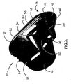
Figure 1 is a perspective view from above of an embodiment of a jug according to the invention; -
Figure 2 is a perspective view from below of the jug shown inFigure 1 ; -
Figure 3 is a side view of the jug shown inFigures 1 and2 ; -
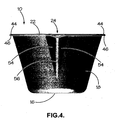
Figure 4 is a first end view of the jug shown inFigures 1 to 3 , as viewed looking from left to right inFigure 3 ; -
Figure 5 is a second end view of the jug shown inFigures 1 to 4 , as viewed looking from right to left inFigure 3 ; -
Figure 6 is a plan view of the jug shown inFigures 1 to 5 ; and -
Figure 7 is a view from below of the jug shown inFigures 1 to 6 . - In
Figures 1 to 7 , ajug 10 manufactured from moulded paper pulp comprises an upwardly open hollow receptacle having a main liquid-receivingportion 12, which communicates with agrip portion 14. The main liquid-receivingportion 12 comprises a flat, generallycircular base wall 16 and asidewall 18 extending upwardly from thebase wall 16. Thesidewall 18 tapers inwardly from itsupper edge 20 towards thebase wall 16 and the upper edge of thesidewall 18 is formed into an overturnedlip 22. Thelip 22 is formed into a pouringspout 24 at a position on the opposite side of the base wall from thegrip portion 14. When viewed from above thejug 10 has a teardrop shape and is wider towards the spout than towards thegrip portion 14. - The
grip portion 14 comprises a generally flatbase wall portion 26 which is located above the level of thebase wall 16 of the main liquid-receivingportion 12, and a taperedsidewall 28, which extends upwardly from thebase wall 26 and merges smoothly with thesidewall 18 of the main liquid-receivingportion 12. The upper edge of thesidewall 28 is formed into an overturnedlip 30, which merges smoothly with thelip 22 of the main liquid-receivingportion 12. - The
sidewall 28 of thegrip portion 14 is formed into two opposed finger recesses 32 on opposite sides of thegrip portion 14, which project into the interior of thejug 10. The upper end of each of the finger recesses 32 is defined by a generallyplanar face 34, which forms a shoulder in the interior of thejug 10. The recesses allow the user's hand to grip thegrip portion 14. - The
jug 10 is moulded from paper pulp as a single unitary item and all of the features of the jug including thebase wall 16, overturnedlip 22,spout 24,grip portion 14, overturnedlip 30, etc. are formed integrally with each other. - In use, a user's hand grips the
grip portion 14 such that his/her thumb and forefinger simultaneously engage opposite finger recesses 32 and shoulders 34. The user's three remaining fingers engage one of the finger recesses 32 at points located below the height of theshoulders 34, and aconvex portion 36 of thegrip 14 engages the user's palm. - A stiffening
shoulder 38 located at a level between thelip 30 of thejug 10 and theshoulders 34 serves to stiffen thejug 10 in the vicinity of thegrip portion 14. The stiffeningshoulder 38 comprises aradiused edge 40 and a generally flat, u-shaped shelf portion 42 (when viewed from above) that extends around the rear half of thejug 10. Theshelf portion 42 is widest at the rear of thejug 10 where it aligns with theconvex portion 36 of thegrip 14, and tapers at either end to blend into thesidewalls 18 of thejug 10 at a point located above thecircular base wall 16 thereof. - The
rim jug 10 comprises an outwardly directedflange 44 and an overturnedperipheral lip portion 46. The overturnedperipheral lip portion 46 has a small internal radius of curvature, which radius is approximately 2mm. - As can be seen best from
Figure 3 , the majority of thelip jug 10 lies in a first generallyflat plane 50. However, in the vicinity of thespout 24, thelip 22 lies in a second,flat plane 52 inclined with respect to thefirst plane 50. In the vicinity of thespout 24, thelip 22 comprises an outwardly directedflange portion 44, but has no overturned portion. - The
spout 24 comprises a pair of generally flat, triangular wall portions/surfaces 54 whose edges meet along avalley line 56 to form a generally v-section channel that intersects, and extends downwardly from, thelip 22 of thejug 10 towards thebase wall 16. The v-section channel guides liquid within theliquid receiving volume spout 24 during pouring. - The internal surface of the
sidewall 18 is provided with ascale 58 for indicating the quantity of liquid (not shown) within theliquid receiving volume 12. Thescale 58 is comprised of integrally moulded indentions in thesidewall 18 that form the major and minor graduations of thescale 58. Numbers and letters are also integrally formed in thesidewall 18 of thejug 10 to facilitate reading thescale 58. - The pouring
spout 24 and thegrip portion 14 lie on a plane passing perpendicularly through thebase wall 16, about which the lug is symmetrical (apart from the scale 58).
Claims (9)
- A moulded paper pulp jug (10) comprising a flat or substantially flat base Wall (16) and a sid ewal (18) extending upwardly from the base wall to define a liquid receiving volume (12), the sidewall (18) being shaped to form a grip portion (14) having first and second opposed finger-receiving recessed portions (32) and a pouring spout (24) on the opposite side of the jug from the grip portion, the sidewall (18) further comprising a plurality of integrally-formed projections and/or indentations arranged to indicate, in use, the depth of liquid within the liquid receiving volume wherein each of the said opposed recesses (32) in the sidewall (18) comprises a gripping surface comprising a concavity in the exterior of the sidewall (18) which forms a projection projecting into the liquid receiving volume and comprising a shoulder portion (34) at its upper end and wherein the grip portion (14) comprises a base wall (26) located above the level of the jug base wall (16), and comprises a tapered side wall (28).
- A jug as claimed in claim 1, wherein the plurality of integrally-formed projections and/or indentations together form a graduated scale (58).
- A jug as claimed in claim 1 or claim 2, wherein the indentions/projections comprise dots and/or dashes and/or letters and/or numerals.
- A jug as claimed in any of the preceding claims, wherein the sidewall (18) comprises an upper peripheral edge (20) and the recessed portions (32) are located below the upper peripheral edge of the sidewall (18).
- A jug as claimed in any of the preceding claims, wherein the shoulder portion (34) comprises a substantially planar portion.
- A jug as claimed in any of the preceding claims, wherein the substantially planar portion extends substantially parallel to the base wall (16).
- A jug as claimed in any of the preceding claims, wherein the upper edge (20) of the sidewall (18) defines the periphery of an opening located above the base wall (16) and further comprising a stiffening shoulder (38) in the vicinity of thegrip means (14).
- A jug as claimed in any of the preceding claims, wherein the sidewall (18) comprises a spout (24) comprising a v-shaped channel that intersects, and extends downwardly from, the upper edge (20) of the sidewall (18) towards the base wall (16), and wherein the upper edge (20) of the sidewall is overturned, except in the region of the spout (24).
- A jug as claimed in any of the preceding claims, comprising an overturned upper edge (46) of the sidewall (18), wherein the radius of curvature of the overturned upper edge (46) of the sidewall is less than ten millimetres.
Applications Claiming Priority (2)
| Application Number | Priority Date | Filing Date | Title |
|---|---|---|---|
| GB0718574A GB2449721A (en) | 2007-09-24 | 2007-09-24 | Receptacles, particularly of moulded paper pulp |
| PCT/GB2008/050853 WO2008152430A2 (en) | 2007-09-24 | 2008-09-23 | Integrally formed receptacle with depth marks on the sidewall |
Publications (2)
| Publication Number | Publication Date |
|---|---|
| EP2203722A2 EP2203722A2 (en) | 2010-07-07 |
| EP2203722B1 true EP2203722B1 (en) | 2015-08-12 |
Family
ID=38670392
Family Applications (1)
| Application Number | Title | Priority Date | Filing Date |
|---|---|---|---|
| EP08806669.1A Active EP2203722B1 (en) | 2007-09-24 | 2008-09-23 | Integrally formed receptacle with depth marks on the sidewall |
Country Status (7)
| Country | Link |
|---|---|
| US (1) | US20100243723A1 (en) |
| EP (1) | EP2203722B1 (en) |
| AU (1) | AU2008263592A1 (en) |
| CA (1) | CA2700451C (en) |
| GB (1) | GB2449721A (en) |
| WO (1) | WO2008152430A2 (en) |
| ZA (1) | ZA201002759B (en) |
Families Citing this family (11)
| Publication number | Priority date | Publication date | Assignee | Title |
|---|---|---|---|---|
| AU2009322077C1 (en) * | 2008-12-02 | 2019-02-14 | Slattery Group Holdings Pty Ltd | Improved drink holder |
| USD705083S1 (en) * | 2011-06-01 | 2014-05-20 | Slattery Group Holdings Pty, Ltd. | Drink holder |
| US20130313271A1 (en) * | 2012-05-22 | 2013-11-28 | Richard Frank Speciale | Training drinking cup |
| US9359110B2 (en) * | 2013-04-15 | 2016-06-07 | Jill Dudik | Clip and pour |
| USD846410S1 (en) * | 2016-11-09 | 2019-04-23 | Ut Brands Llc | Measuring cup and funnel set |
| AU201713695S (en) | 2017-01-31 | 2017-08-15 | Henkel Ag & Co Kgaa | Dosing cap (for Detergents) |
| CN210520696U (en) * | 2019-09-25 | 2020-05-15 | 江苏绿森包装有限公司 | Paper pulp molding folding spoon |
| US20210222813A1 (en) * | 2020-01-16 | 2021-07-22 | Performance Pulsation Control, Inc. | Reactive fluid system accounting for thermal expansion in replacement of nitrogen within charged pulsation control equipment |
| EP4435176A3 (en) * | 2020-01-17 | 2024-11-27 | Société des Produits Nestlé S.A. | Recyclable dosing device |
| WO2021198290A1 (en) | 2020-03-30 | 2021-10-07 | Société des Produits Nestlé S.A. | Dosing device |
| US11933652B1 (en) * | 2023-05-02 | 2024-03-19 | Joseph B. Feuchtwanger, III | Flushable urine collector with volume indicator |
Citations (1)
| Publication number | Priority date | Publication date | Assignee | Title |
|---|---|---|---|---|
| US2023470A (en) * | 1933-11-03 | 1935-12-10 | John M Hart | Molded pulp article |
Family Cites Families (25)
| Publication number | Priority date | Publication date | Assignee | Title |
|---|---|---|---|---|
| US1986824A (en) * | 1933-01-09 | 1935-01-08 | American Lace Paper Company | Receptacle of molded pulp |
| US2135045A (en) | 1934-05-04 | 1938-11-01 | Westinghouse Electric & Mfg Co | Control for welding generators |
| US2165045A (en) * | 1938-02-16 | 1939-07-04 | Garside Elena May | Calibrated self-supporting sanitary spoon |
| GB668241A (en) * | 1950-01-12 | 1952-03-12 | Bbc Brown Boveri & Cie | Rectangular container for transport purposes |
| NL7305660A (en) * | 1973-04-24 | 1974-10-28 | ||
| GB2095977B (en) * | 1981-03-20 | 1984-08-30 | Mothercare Ltd | Containers |
| USD274778S (en) * | 1982-07-06 | 1984-07-24 | The Procter & Gamble Company | Scoop |
| EP0332885A1 (en) * | 1988-03-17 | 1989-09-20 | Societe Des Produits Nestle S.A. | Reclosable container made from a synthetic material |
| US5096083A (en) * | 1990-05-08 | 1992-03-17 | Essef Corporation | Polyethylene shipping drum |
| US5201893A (en) * | 1991-07-25 | 1993-04-13 | Vollrath Group, Inc. | Irrigation container and syringe |
| NL1000422C2 (en) * | 1995-05-23 | 1996-11-25 | Wavin Bv | Rectangular container with lid. |
| JPH09123300A (en) * | 1995-11-02 | 1997-05-13 | San Chem Kk | Manufacture of paper-made weighing instrument |
| US5823345A (en) * | 1997-07-24 | 1998-10-20 | Berry Plastics Corporation | Stackable receptacle assembly for pourable products |
| FR2789288B1 (en) * | 1999-02-08 | 2001-03-09 | Alain Jacques Paul Petit | TOILET DEVICE FOR BABIES WHO HAS BEEN BORN |
| JP2004191248A (en) * | 2002-12-12 | 2004-07-08 | Izumi Kasei Kogyo Kk | Weighing spoon |
| US7306120B2 (en) * | 2003-08-07 | 2007-12-11 | Rubbermaid Incorporated | Measuring cup with volume markings visible while pouring |
| US7546932B2 (en) * | 2003-10-01 | 2009-06-16 | Solo Cup Operating Corporation | Ergonomic disposable cup having improved structural integrity |
| JP2005289481A (en) * | 2004-04-02 | 2005-10-20 | Isamu Sato | Food storage container and food storage container manufacturing method |
| EP1627826A3 (en) * | 2004-08-18 | 2006-04-19 | Remia C.V. | Method for producing and packaging a heatable sauce in a container |
| USD524589S1 (en) * | 2004-08-19 | 2006-07-11 | Alice Ink, Inc. | Bowl with friction material |
| US20060076395A1 (en) * | 2004-10-12 | 2006-04-13 | Hayes Thomas J | Container having textured grip and enhanced wall integrity |
| USD530617S1 (en) * | 2004-11-18 | 2006-10-24 | Plastipak Packaging, Inc. | Container |
| US7766185B2 (en) * | 2006-01-11 | 2010-08-03 | Island Oasis Frozen Cocktail Company, Inc. | Detachable spill guard for a blender cup or other container |
| GB2461434B (en) * | 2006-07-31 | 2011-01-05 | Vernacare Ltd | Wash bowl |
| GB2434079B (en) * | 2006-10-27 | 2007-12-19 | Doch & Doris Ltd | Medicine cup combined with gauge for checking risk of objects causing a baby to choke |
-
2007
- 2007-09-24 GB GB0718574A patent/GB2449721A/en not_active Withdrawn
-
2008
- 2008-09-23 US US12/679,353 patent/US20100243723A1/en not_active Abandoned
- 2008-09-23 EP EP08806669.1A patent/EP2203722B1/en active Active
- 2008-09-23 WO PCT/GB2008/050853 patent/WO2008152430A2/en not_active Ceased
- 2008-09-23 AU AU2008263592A patent/AU2008263592A1/en not_active Abandoned
- 2008-09-23 CA CA2700451A patent/CA2700451C/en active Active
-
2010
- 2010-04-20 ZA ZA2010/02759A patent/ZA201002759B/en unknown
Patent Citations (1)
| Publication number | Priority date | Publication date | Assignee | Title |
|---|---|---|---|---|
| US2023470A (en) * | 1933-11-03 | 1935-12-10 | John M Hart | Molded pulp article |
Also Published As
| Publication number | Publication date |
|---|---|
| CA2700451C (en) | 2018-02-13 |
| AU2008263592A1 (en) | 2008-12-18 |
| GB2449721A (en) | 2008-12-03 |
| CA2700451A1 (en) | 2009-12-18 |
| WO2008152430A3 (en) | 2009-05-07 |
| WO2008152430A2 (en) | 2008-12-18 |
| US20100243723A1 (en) | 2010-09-30 |
| WO2008152430A4 (en) | 2009-07-23 |
| EP2203722A2 (en) | 2010-07-07 |
| GB0718574D0 (en) | 2007-10-31 |
| ZA201002759B (en) | 2011-06-29 |
Similar Documents
| Publication | Publication Date | Title |
|---|---|---|
| CA2700451C (en) | Receptacles | |
| CA1151860A (en) | Cutlery | |
| US8382730B2 (en) | Surgical fluid basin | |
| US5555892A (en) | Biopsy shaver | |
| CA2353056C (en) | Vessel with measuring capability | |
| US5678450A (en) | Adjustable measurement container | |
| AU2010226256B2 (en) | Pouring device with deformable spout | |
| CN106796134A (en) | For the measuring cup of detergent composition | |
| EP4090919B1 (en) | Dosing cups and medicinal fluid delivery systems | |
| EP1142522A1 (en) | Flexible element for forming a piece of cutlery | |
| JP6192225B2 (en) | Weighing cap | |
| JP4949078B2 (en) | Toride | |
| USRE39827E1 (en) | Vessel with measuring capability | |
| CN210749284U (en) | Urine collecting cup | |
| JP3249235U (en) | Packaging Bag | |
| JPH0518673Y2 (en) | ||
| JPS6331670Y2 (en) | ||
| JP3490928B2 (en) | Pail | |
| WO2025136094A1 (en) | Piping bag cutting tool | |
| KR200290467Y1 (en) | Spoon hanging structure of powder container | |
| WO2006071016A1 (en) | Measuring rule having function of division and multiplication | |
| GB2374146A (en) | Pasta apportioning device | |
| JP5243152B2 (en) | Squeeze container | |
| KR20150002690U (en) | Sanitary cup | |
| JP2004321230A (en) | Beverage cup for child |
Legal Events
| Date | Code | Title | Description |
|---|---|---|---|
| PUAI | Public reference made under article 153(3) epc to a published international application that has entered the european phase |
Free format text: ORIGINAL CODE: 0009012 |
|
| 17P | Request for examination filed |
Effective date: 20100423 |
|
| AK | Designated contracting states |
Kind code of ref document: A2 Designated state(s): AT BE BG CH CY CZ DE DK EE ES FI FR GB GR HR HU IE IS IT LI LT LU LV MC MT NL NO PL PT RO SE SI SK TR |
|
| AX | Request for extension of the european patent |
Extension state: AL BA MK RS |
|
| 17Q | First examination report despatched |
Effective date: 20111202 |
|
| DAX | Request for extension of the european patent (deleted) | ||
| GRAP | Despatch of communication of intention to grant a patent |
Free format text: ORIGINAL CODE: EPIDOSNIGR1 |
|
| INTG | Intention to grant announced |
Effective date: 20150302 |
|
| GRAS | Grant fee paid |
Free format text: ORIGINAL CODE: EPIDOSNIGR3 |
|
| GRAA | (expected) grant |
Free format text: ORIGINAL CODE: 0009210 |
|
| AK | Designated contracting states |
Kind code of ref document: B1 Designated state(s): AT BE BG CH CY CZ DE DK EE ES FI FR GB GR HR HU IE IS IT LI LT LU LV MC MT NL NO PL PT RO SE SI SK TR |
|
| REG | Reference to a national code |
Ref country code: GB Ref legal event code: FG4D |
|
| REG | Reference to a national code |
Ref country code: CH Ref legal event code: EP |
|
| REG | Reference to a national code |
Ref country code: AT Ref legal event code: REF Ref document number: 742580 Country of ref document: AT Kind code of ref document: T Effective date: 20150815 |
|
| REG | Reference to a national code |
Ref country code: IE Ref legal event code: FG4D |
|
| REG | Reference to a national code |
Ref country code: DE Ref legal event code: R096 Ref document number: 602008039550 Country of ref document: DE |
|
| REG | Reference to a national code |
Ref country code: LT Ref legal event code: MG4D |
|
| REG | Reference to a national code |
Ref country code: AT Ref legal event code: MK05 Ref document number: 742580 Country of ref document: AT Kind code of ref document: T Effective date: 20150812 |
|
| REG | Reference to a national code |
Ref country code: NL Ref legal event code: MP Effective date: 20150812 |
|
| PG25 | Lapsed in a contracting state [announced via postgrant information from national office to epo] |
Ref country code: LT Free format text: LAPSE BECAUSE OF FAILURE TO SUBMIT A TRANSLATION OF THE DESCRIPTION OR TO PAY THE FEE WITHIN THE PRESCRIBED TIME-LIMIT Effective date: 20150812 Ref country code: LV Free format text: LAPSE BECAUSE OF FAILURE TO SUBMIT A TRANSLATION OF THE DESCRIPTION OR TO PAY THE FEE WITHIN THE PRESCRIBED TIME-LIMIT Effective date: 20150812 Ref country code: GR Free format text: LAPSE BECAUSE OF FAILURE TO SUBMIT A TRANSLATION OF THE DESCRIPTION OR TO PAY THE FEE WITHIN THE PRESCRIBED TIME-LIMIT Effective date: 20151113 Ref country code: FI Free format text: LAPSE BECAUSE OF FAILURE TO SUBMIT A TRANSLATION OF THE DESCRIPTION OR TO PAY THE FEE WITHIN THE PRESCRIBED TIME-LIMIT Effective date: 20150812 Ref country code: NO Free format text: LAPSE BECAUSE OF FAILURE TO SUBMIT A TRANSLATION OF THE DESCRIPTION OR TO PAY THE FEE WITHIN THE PRESCRIBED TIME-LIMIT Effective date: 20151112 |
|
| PG25 | Lapsed in a contracting state [announced via postgrant information from national office to epo] |
Ref country code: IS Free format text: LAPSE BECAUSE OF FAILURE TO SUBMIT A TRANSLATION OF THE DESCRIPTION OR TO PAY THE FEE WITHIN THE PRESCRIBED TIME-LIMIT Effective date: 20151212 Ref country code: ES Free format text: LAPSE BECAUSE OF FAILURE TO SUBMIT A TRANSLATION OF THE DESCRIPTION OR TO PAY THE FEE WITHIN THE PRESCRIBED TIME-LIMIT Effective date: 20150812 Ref country code: AT Free format text: LAPSE BECAUSE OF FAILURE TO SUBMIT A TRANSLATION OF THE DESCRIPTION OR TO PAY THE FEE WITHIN THE PRESCRIBED TIME-LIMIT Effective date: 20150812 Ref country code: SE Free format text: LAPSE BECAUSE OF FAILURE TO SUBMIT A TRANSLATION OF THE DESCRIPTION OR TO PAY THE FEE WITHIN THE PRESCRIBED TIME-LIMIT Effective date: 20150812 Ref country code: PT Free format text: LAPSE BECAUSE OF FAILURE TO SUBMIT A TRANSLATION OF THE DESCRIPTION OR TO PAY THE FEE WITHIN THE PRESCRIBED TIME-LIMIT Effective date: 20151214 Ref country code: HR Free format text: LAPSE BECAUSE OF FAILURE TO SUBMIT A TRANSLATION OF THE DESCRIPTION OR TO PAY THE FEE WITHIN THE PRESCRIBED TIME-LIMIT Effective date: 20150812 Ref country code: PL Free format text: LAPSE BECAUSE OF FAILURE TO SUBMIT A TRANSLATION OF THE DESCRIPTION OR TO PAY THE FEE WITHIN THE PRESCRIBED TIME-LIMIT Effective date: 20150812 |
|
| PG25 | Lapsed in a contracting state [announced via postgrant information from national office to epo] |
Ref country code: NL Free format text: LAPSE BECAUSE OF FAILURE TO SUBMIT A TRANSLATION OF THE DESCRIPTION OR TO PAY THE FEE WITHIN THE PRESCRIBED TIME-LIMIT Effective date: 20150812 |
|
| PG25 | Lapsed in a contracting state [announced via postgrant information from national office to epo] |
Ref country code: IT Free format text: LAPSE BECAUSE OF FAILURE TO SUBMIT A TRANSLATION OF THE DESCRIPTION OR TO PAY THE FEE WITHIN THE PRESCRIBED TIME-LIMIT Effective date: 20150812 Ref country code: EE Free format text: LAPSE BECAUSE OF FAILURE TO SUBMIT A TRANSLATION OF THE DESCRIPTION OR TO PAY THE FEE WITHIN THE PRESCRIBED TIME-LIMIT Effective date: 20150812 Ref country code: CZ Free format text: LAPSE BECAUSE OF FAILURE TO SUBMIT A TRANSLATION OF THE DESCRIPTION OR TO PAY THE FEE WITHIN THE PRESCRIBED TIME-LIMIT Effective date: 20150812 Ref country code: SK Free format text: LAPSE BECAUSE OF FAILURE TO SUBMIT A TRANSLATION OF THE DESCRIPTION OR TO PAY THE FEE WITHIN THE PRESCRIBED TIME-LIMIT Effective date: 20150812 Ref country code: DK Free format text: LAPSE BECAUSE OF FAILURE TO SUBMIT A TRANSLATION OF THE DESCRIPTION OR TO PAY THE FEE WITHIN THE PRESCRIBED TIME-LIMIT Effective date: 20150812 |
|
| REG | Reference to a national code |
Ref country code: CH Ref legal event code: PL |
|
| REG | Reference to a national code |
Ref country code: DE Ref legal event code: R097 Ref document number: 602008039550 Country of ref document: DE |
|
| PG25 | Lapsed in a contracting state [announced via postgrant information from national office to epo] |
Ref country code: RO Free format text: LAPSE BECAUSE OF FAILURE TO SUBMIT A TRANSLATION OF THE DESCRIPTION OR TO PAY THE FEE WITHIN THE PRESCRIBED TIME-LIMIT Effective date: 20150812 Ref country code: MC Free format text: LAPSE BECAUSE OF FAILURE TO SUBMIT A TRANSLATION OF THE DESCRIPTION OR TO PAY THE FEE WITHIN THE PRESCRIBED TIME-LIMIT Effective date: 20150812 |
|
| PLBE | No opposition filed within time limit |
Free format text: ORIGINAL CODE: 0009261 |
|
| STAA | Information on the status of an ep patent application or granted ep patent |
Free format text: STATUS: NO OPPOSITION FILED WITHIN TIME LIMIT |
|
| REG | Reference to a national code |
Ref country code: IE Ref legal event code: MM4A |
|
| 26N | No opposition filed |
Effective date: 20160513 |
|
| PG25 | Lapsed in a contracting state [announced via postgrant information from national office to epo] |
Ref country code: CH Free format text: LAPSE BECAUSE OF NON-PAYMENT OF DUE FEES Effective date: 20150930 Ref country code: LI Free format text: LAPSE BECAUSE OF NON-PAYMENT OF DUE FEES Effective date: 20150930 Ref country code: IE Free format text: LAPSE BECAUSE OF NON-PAYMENT OF DUE FEES Effective date: 20150923 |
|
| REG | Reference to a national code |
Ref country code: FR Ref legal event code: PLFP Year of fee payment: 9 |
|
| PG25 | Lapsed in a contracting state [announced via postgrant information from national office to epo] |
Ref country code: SI Free format text: LAPSE BECAUSE OF FAILURE TO SUBMIT A TRANSLATION OF THE DESCRIPTION OR TO PAY THE FEE WITHIN THE PRESCRIBED TIME-LIMIT Effective date: 20150812 |
|
| PG25 | Lapsed in a contracting state [announced via postgrant information from national office to epo] |
Ref country code: BE Free format text: LAPSE BECAUSE OF FAILURE TO SUBMIT A TRANSLATION OF THE DESCRIPTION OR TO PAY THE FEE WITHIN THE PRESCRIBED TIME-LIMIT Effective date: 20150812 |
|
| PG25 | Lapsed in a contracting state [announced via postgrant information from national office to epo] |
Ref country code: MT Free format text: LAPSE BECAUSE OF FAILURE TO SUBMIT A TRANSLATION OF THE DESCRIPTION OR TO PAY THE FEE WITHIN THE PRESCRIBED TIME-LIMIT Effective date: 20150812 |
|
| PG25 | Lapsed in a contracting state [announced via postgrant information from national office to epo] |
Ref country code: HU Free format text: LAPSE BECAUSE OF FAILURE TO SUBMIT A TRANSLATION OF THE DESCRIPTION OR TO PAY THE FEE WITHIN THE PRESCRIBED TIME-LIMIT; INVALID AB INITIO Effective date: 20080923 Ref country code: BG Free format text: LAPSE BECAUSE OF FAILURE TO SUBMIT A TRANSLATION OF THE DESCRIPTION OR TO PAY THE FEE WITHIN THE PRESCRIBED TIME-LIMIT Effective date: 20150812 |
|
| PG25 | Lapsed in a contracting state [announced via postgrant information from national office to epo] |
Ref country code: CY Free format text: LAPSE BECAUSE OF FAILURE TO SUBMIT A TRANSLATION OF THE DESCRIPTION OR TO PAY THE FEE WITHIN THE PRESCRIBED TIME-LIMIT Effective date: 20150812 |
|
| REG | Reference to a national code |
Ref country code: FR Ref legal event code: PLFP Year of fee payment: 10 |
|
| PG25 | Lapsed in a contracting state [announced via postgrant information from national office to epo] |
Ref country code: TR Free format text: LAPSE BECAUSE OF FAILURE TO SUBMIT A TRANSLATION OF THE DESCRIPTION OR TO PAY THE FEE WITHIN THE PRESCRIBED TIME-LIMIT Effective date: 20150812 |
|
| PG25 | Lapsed in a contracting state [announced via postgrant information from national office to epo] |
Ref country code: LU Free format text: LAPSE BECAUSE OF NON-PAYMENT OF DUE FEES Effective date: 20150923 |
|
| REG | Reference to a national code |
Ref country code: FR Ref legal event code: PLFP Year of fee payment: 11 |
|
| REG | Reference to a national code |
Ref country code: DE Ref legal event code: R082 Ref document number: 602008039550 Country of ref document: DE Representative=s name: HOEGER, STELLRECHT & PARTNER PATENTANWAELTE MB, DE |
|
| P01 | Opt-out of the competence of the unified patent court (upc) registered |
Effective date: 20230602 |
|
| PGFP | Annual fee paid to national office [announced via postgrant information from national office to epo] |
Ref country code: DE Payment date: 20250919 Year of fee payment: 18 |
|
| PGFP | Annual fee paid to national office [announced via postgrant information from national office to epo] |
Ref country code: GB Payment date: 20250813 Year of fee payment: 18 |
|
| PGFP | Annual fee paid to national office [announced via postgrant information from national office to epo] |
Ref country code: FR Payment date: 20250902 Year of fee payment: 18 |