EP2203039A2 - Automotive inverter assembly - Google Patents
Automotive inverter assembly Download PDFInfo
- Publication number
- EP2203039A2 EP2203039A2 EP10160215A EP10160215A EP2203039A2 EP 2203039 A2 EP2203039 A2 EP 2203039A2 EP 10160215 A EP10160215 A EP 10160215A EP 10160215 A EP10160215 A EP 10160215A EP 2203039 A2 EP2203039 A2 EP 2203039A2
- Authority
- EP
- European Patent Office
- Prior art keywords
- inverter assembly
- volume
- wall
- component
- supporting body
- Prior art date
- Legal status (The legal status is an assumption and is not a legal conclusion. Google has not performed a legal analysis and makes no representation as to the accuracy of the status listed.)
- Granted
Links
Images



Classifications
-
- H—ELECTRICITY
- H05—ELECTRIC TECHNIQUES NOT OTHERWISE PROVIDED FOR
- H05K—PRINTED CIRCUITS; CASINGS OR CONSTRUCTIONAL DETAILS OF ELECTRIC APPARATUS; MANUFACTURE OF ASSEMBLAGES OF ELECTRICAL COMPONENTS
- H05K7/00—Constructional details common to different types of electric apparatus
- H05K7/20—Modifications to facilitate cooling, ventilating, or heating
- H05K7/2089—Modifications to facilitate cooling, ventilating, or heating for power electronics, e.g. for inverters for controlling motor
- H05K7/20927—Liquid coolant without phase change
Definitions
- the present invention relates to an automotive inverter assembly, in particular for an electric, hybrid or fuel-cell vehicle.
- the invention also relates to a propulsion system comprising such an inverter assembly, and to a vehicle equipped with such an inverter assembly.
- a hybrid vehicle is a vehicle powered by two or more drive systems. Most commonly, the term refers to hybrid electric vehicles (HEVs) which feature a conventional drive system, such as an internal combustion engine, combined with one or more electric motors.
- HEVs hybrid electric vehicles
- PHEVs hybrid electric vehicles
- PHEVs plug-in hybrid electric vehicles
- vehicles which, in addition to a conventional (e.g. internal combustion) engine and an electric motor, also feature a system of batteries chargeable by plugging in to an electric power source.
- PHEVs normally also comprise an electric drive system in turn comprising: a power inverter assembly; a low-voltage battery charger for charging a service battery from the high-voltage traction battery; and a high-voltage battery charger, connectable to the power mains, for charging the traction battery.
- a PHEV normally employs connectors to supply electric power from the batteries (for which fuel cells may be substituted) to the internal combustion engine and other devices and electric systems on the vehicle.
- the inverter assemblies of such vehicles serve to convert the direct current from the batteries or alternative sources to alternating current to power the vehicle user devices mentioned.
- an automotive inverter assembly as claimed in Claim 1.
- Figure 1 shows a propulsion system 100, for a hybrid vehicle (not shown), the propulsion system substantially comprising:
- Electric drive 104 in turn comprises: an inverter assembly 1; a low-voltage battery charger 105 for charging a service battery 106 from a high-voltage traction battery 107; and a high-voltage battery charger 108 for charging traction battery 107, and which is connectable to the power mains 109, and substantially comprises an active power factor correction AC/DC converter 110 at the input, and a DC/DC converter 111 at the output.
- the Figure 1 propulsion system 100 performs at least the following functions:
- transmission 102 is connected functionally to electric machine 103.
- Inverter assembly 1 controls electric power flow to the system's motor-generator, and so supplies the necessary electric power when the vehicle is driven by electric machine 103 on its own or in conjunction with combustion engine 101. Inverter assembly 1 also controls electric machine 103 operating in electric generator mode during regenerative braking, to feed electric power to high-voltage battery 107.
- Inverter assembly 1 comprises a number of electric/electronic components 20, including an IGBT module and a power capacitor on the high-voltage DC bus.
- components 20 Figures 2-9 ) produce considerable heat, which must be removed to avoid overheating and ensure the best operating conditions.
- Inverter assembly 1 advantageously comprises a supporting body 2 for supporting components 20, and which defines at least part of a volume 3 ( Figure 6 ), through which flows a cooling fluid coupled thermally with components 20 to be cooled.
- Supporting body 2 comprises a first and second wall 4 and 5, substantially parallel and opposite, and which vertically define volume 3 in between.
- First and second wall 4 and 5 of supporting body 2 are preferably connected releasably (e.g. by screws inserted inside threaded seats) and hermetically (e.g. with the interposition of a seal) along respective peripheries p.
- Wall 4 has a first face 4A and a second face 4B substantially parallel to each other, with face 4A located on top with reference to Figure 6 .
- wall 5 has a first face 5A and a second face 5B substantially parallel to each other, with face 5A located on top with reference to Figure 6 . Faces 4B and 5A are oppositely facing, and are flowed over by the cooling fluid.
- Supporting body 2 has fastening holes 21 on walls 4 and 5 for assembling components 20 ( Figures 6 and 7 ).
- Face 4A of wall 4 advantageously has a number of dead seats 17 for housing respective components 20 to be cooled.
- seats 17 are adjacent to holes 21.
- Components 20 are thus coupled thermally with supporting body 2 and, in series with this, with the cooling fluid flowing through volume 3.
- Seats 17 define thin portions of wall 4, i.e. of first wall 4 of supporting body 2.
- At least one surface of volume 3 flowed over, in use, by the cooling fluid e.g. top face 5A ( Figures 6 and 8 ), preferably comprises a number of fins 16 facing inwards of volume 3, so as also to be flowed over by the cooling fluid.
- Fins 16 increase the heat exchange surface per unit of volume, and promote turbulent flow of the cooling fluid, to advantageously improve heat exchange efficiency.
- Fins 16 are defined by pegs substantially perpendicular to faces 5A and 4B and of a length substantially equal to the distance between walls 4 and 5.
- groups of fins 16 may conveniently be welded to one another at welds extending between walls 4 and 5, and which define deflectors 15 for directing the cooling fluid, in use, along a preferential path.
- inverter assembly 1 may comprise deflectors 15 defined by one or more partitions inside volume 3, e.g. interposed between first and second wall 4 and 5.
- the part of the cooling fluid prevented from flowing through deflectors 15 may thus be directed through volume 3 along a non-straight path.
- Supporting body 2 also comprises lateral walls 6, 7, 8, 9, which are substantially perpendicular to first and second wall 4 and 5, are parallel two by two, and laterally define volume 3 through which the cooling fluid flows.
- volume 3 extends between walls 4 and 5 and the portions of walls 6, 7, 8, 9 defined between walls 4 and 5.
- Walls 6 and 7 are opposite and substantially parallel to walls 8 and 9 respectively.
- Wall 7 is higher than wall 9.
- walls 6 and 8 extend between walls 7 and 9, and taper from wall 7 to wall 9.
- Openings are formed in walls 6, 7, 8 to insert cables or connectors for connecting components 20 of inverter assembly 1 electrically, as shown in the Figure 1 diagram of the hybrid drive.
- Walls 6, 7, 8 of supporting body 2 also laterally define at least part of a volume 10 housing components 20 to be cooled.
- Inverter assembly 1 also comprises a top and bottom half-casing 11, 12 ( Figure 2 ) located on opposite sides of walls 4 and 5 to volume 3.
- half-casing 11, face 4A, and the portions of walls 6, 7, 8 on the opposite side of face 4A to volume 3 define volume 10 housing components 20.
- Half-casings 11 and 12 are fixed removably to walls 6, 7, 8, 9, and impart a parallelepiped shape to supporting body 2 as a whole.
- lateral wall 9 laterally defines volume 3, through which the cooling fluid flows, but not volume 10 housing components 20. So, when half-casings 11 and 12 are not fixed to supporting body 2, volume 10 is easily accessible to assemble components 20.
- Supporting body 2 also comprises an inlet 13 connected hydraulically to a pump (not shown) to feed cooling fluid into volume 3; and an outlet 14 for draining the cooling fluid flowing through volume 3.
- the heat produced, during operation of propulsion system 100 of the vehicle, by components 20 of inverter assembly 1, which are fixed inside dead seats 17 and/or holes 21 in the supporting body, is removed by feeding into volume 3 an appropriate amount of cooling fluid, e.g. water, which may possibly be regulated according to the amount of heat generated. More specifically, the cooling fluid is pumped through inlet 13 into volume 3, flows through volume 3, and is drained from outlet 14 on the opposite side.
- cooling fluid e.g. water
- the cooling fluid flows over the walls of volume 3, and in particular over face 5A with fins 16, and over face 4B, and so removes from volume 3 the heat yielded to it by components 20 fixed to walls 4 and 5 of supporting body 2.
- Cooling fluid flow through volume 3 may advantageously be made more circuitous by deflectors 15 described above, which, in use, direct the cooling fluid inside volume 3 along a preferential, non-straight, e.g. zig-zag, path between inlet 13 and outlet 14.
- dead seats 17 also define thinner portions of wall 4, i.e. of first wall 4 of supporting body 2, which reduce the heat conduction resistance of wall 4, and so improve thermal coupling of components 20 and supporting body 2 and, indirectly, cooling of components 20 by the cooling fluid flowing through volume 3.
- Number 2' in Figure 10 indicates the supporting body of an inverter assembly 1' in accordance with the invention.
- Inverter assembly 1' will be described only in what it differs from inverter assembly 1, and any corresponding or equivalent parts of inverter assemblies 1, 1' are indicated, where possible, using the same reference numbers.
- Wall 5' of supporting body 2' has through seats 18 in which to fix components 20, so that components 20 face inwards of volume 3 and have, in use, one surface flowed over directly by the cooling fluid.
- Components 20 are housed hermetically inside through seats 18, e.g. by inserting a seal between the periphery of components 20 and the edges of through seats 18.
- Components 20 each have a surface 22, over which cooling fluid flows in use, and which has fins 16, identical to those of face 5A of supporting body 2, to increase the direct heat exchange surface between the cooling fluid and components 20.
- inverter assembly 1' Operation of inverter assembly 1' is described below only insofar as it differs from that of inverter assembly 1.
- the cooling fluid pumped into volume 3 flows directly over the surfaces of components 20 housed in through seats 18, thus improving heat exchange efficiency by eliminating the conduction heat exchange component involved in the inverter assembly 1 by interposing wall 4 or 5 between components 20 and the cooling fluid.
- Providing fins 16 on surfaces 22 of components 20 exposed to the cooling fluid further improves heat exchange efficiency by increasing the heat exchange surface.
- inverter assembly 1' according to the present invention will be clear from the above description.
- inverter assembly 1' Compared with solutions employing a coil to cool components 20, inverter assembly 1' according to the invention provides for more effective heat exchange by greatly increasing the heat exchange surface per unit of volume.
- the cooling fluid undergoes much smaller load losses than a cooling coil, on account of the much larger flow section and, at the same time, the shorter distance the cooling fluid has to travel. Smaller load losses mean less energy is expended in circulating the cooling fluid, and so also reduce the overall energy cost of the vehicle.
- Inverter assembly 1' features a built-in heat dissipater substantially defined by supporting body 2, to which components 20 to be cooled are fixed, and which is coupled thermally with both the components themselves and a cooling fluid.
- Inverter assembly 1' is therefore highly compact and lightweight, and so aids in improving vehicle performance in terms of energy efficiency, consumption, and environmental impact.
- Heat exchange with the flowed-over surfaces is made more effective by deflectors 15, which reduce the likelihood of stagnation.
- Heat exchange with the flowed-over surfaces is also made more effective by fins 16, which greatly increase the heat exchange surface and turbulent flow of the cooling fluid.
- volume 10 housing components 20 is bounded by half-casing 11, wall 4, and portions of walls 6, 7, 8, inverter assembly 1' is extremely easy to assemble.
- inverter assembly 1' as described and illustrated herein without, however, departing from the scope of the accompanying Claims.
- inverter assembly 1' may be applied to an all-electric, possibly mains-powered, vehicle.
- Walls 4 and 5 may, for example, be formed integrally with supporting body 2.
- one component 20 may define all or most of wall 5.
Landscapes
- Engineering & Computer Science (AREA)
- Microelectronics & Electronic Packaging (AREA)
- Physics & Mathematics (AREA)
- Thermal Sciences (AREA)
- Electric Propulsion And Braking For Vehicles (AREA)
- Inverter Devices (AREA)
- Motor Or Generator Cooling System (AREA)
- Cooling, Air Intake And Gas Exhaust, And Fuel Tank Arrangements In Propulsion Units (AREA)
- Motor Or Generator Frames (AREA)
- Control Of Multiple Motors (AREA)
- Cooling Or The Like Of Electrical Apparatus (AREA)
Abstract
Description
- The present invention relates to an automotive inverter assembly, in particular for an electric, hybrid or fuel-cell vehicle. The invention also relates to a propulsion system comprising such an inverter assembly, and to a vehicle equipped with such an inverter assembly.
- A hybrid vehicle is a vehicle powered by two or more drive systems. Most commonly, the term refers to hybrid electric vehicles (HEVs) which feature a conventional drive system, such as an internal combustion engine, combined with one or more electric motors.
- Of particular interest to researchers have been what are known as "plug-in" hybrid electric vehicles (PHEVs), i.e. vehicles which, in addition to a conventional (e.g. internal combustion) engine and an electric motor, also feature a system of batteries chargeable by plugging in to an electric power source.
- PHEVs normally also comprise an electric drive system in turn comprising: a power inverter assembly; a low-voltage battery charger for charging a service battery from the high-voltage traction battery; and a high-voltage battery charger, connectable to the power mains, for charging the traction battery.
- A PHEV normally employs connectors to supply electric power from the batteries (for which fuel cells may be substituted) to the internal combustion engine and other devices and electric systems on the vehicle.
- The inverter assemblies of such vehicles serve to convert the direct current from the batteries or alternative sources to alternating current to power the vehicle user devices mentioned.
- The electronic components of the inverter assembly, however, produce considerable heat, which must be removed to ensure correct operation and prevent overheating, which means the inverter assembly must be equipped with appropriate cooling means.
- A need is felt within the industry for an inverter assembly, particularly for hybrid vehicles, designed to effectively dissipate the heat generated in use, and more effectively, for example, than conventional solutions employing a cooling coil.
- A need is also felt for an inverter assembly which is compact and lightweight, and provides for improving vehicle performance in terms of energy efficiency, consumption, and therefore environmental impact.
- Finally, a need is also felt for an automotive inverter assembly that is potentially cheaper to produce by being easier to assemble.
- It is an object of the present invention to provide an automotive inverter assembly designed to meet at least one of the above requirements in a straightforward, low-cost manner.
- According to the present invention, there is provided an automotive inverter assembly as claimed in Claim 1.
- A preferred, non-limiting embodiment of the present invention will be described by way of example with reference to the accompanying drawings, in which:
-
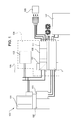
Figure 1 shows an operating diagram of a drive comprising a an automotive inverter assembly; -
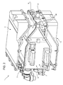
Figure 2 shows a view in perspective of theFigure 1 inverter assembly; -
Figures 3 and4 show views in perspective, from different angles, of theFigure 1 and2 inverter assembly; -
Figure 5 shows an exploded view in perspective of theFigure 2-4 inverter assembly; -
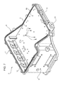
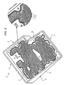
Figures 6 ,7 ,8 ,9 show views in perspective, from respective angles and with parts removed for clarity, of theFigure 2-5 inverter assembly; -
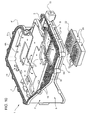
Figure 10 shows a view in perspective of an inverter assembly according to the invention. -
Figure 1 shows apropulsion system 100, for a hybrid vehicle (not shown), the propulsion system substantially comprising: - a combustion engine 101 (e.g. a low-power petrol engine);
- a
transmission 102, e.g. a dual dry clutch transmission (DDCT); - an
electric machine 103, which operates as a motor or electric generator, and can be activated to startcombustion engine 101; and - an
electric power drive 104. -
Electric drive 104 in turn comprises: an inverter assembly 1; a low-voltage battery charger 105 for charging aservice battery 106 from a high-voltage traction battery 107; and a high-voltage battery charger 108 forcharging traction battery 107, and which is connectable to thepower mains 109, and substantially comprises an active power factor correction AC/DC converter 110 at the input, and a DC/DC converter 111 at the output. - The
Figure 1 propulsion system 100 performs at least the following functions: - turn-on/turn-off of
combustion engine 101 byelectric machine 103 operating as an electric drive motor; - vehicle launch and creep in electric mode;
- economy gear shifting;
- regenerative braking;
- electric torque boost.
- In the example shown,
transmission 102 is connected functionally toelectric machine 103. - Inverter assembly 1 controls electric power flow to the system's motor-generator, and so supplies the necessary electric power when the vehicle is driven by
electric machine 103 on its own or in conjunction withcombustion engine 101. Inverter assembly 1 also controlselectric machine 103 operating in electric generator mode during regenerative braking, to feed electric power to high-voltage battery 107. - Inverter assembly 1 comprises a number of electric/
electronic components 20, including an IGBT module and a power capacitor on the high-voltage DC bus. In use, components 20 (Figures 2-9 ) produce considerable heat, which must be removed to avoid overheating and ensure the best operating conditions. - Inverter assembly 1 advantageously comprises a supporting
body 2 for supportingcomponents 20, and which defines at least part of a volume 3 (Figure 6 ), through which flows a cooling fluid coupled thermally withcomponents 20 to be cooled. -
Supporting body 2 comprises a first andsecond wall volume 3 in between. - First and
second wall body 2 are preferably connected releasably (e.g. by screws inserted inside threaded seats) and hermetically (e.g. with the interposition of a seal) along respective peripheries p.Wall 4 has afirst face 4A and asecond face 4B substantially parallel to each other, withface 4A located on top with reference toFigure 6 . - Similarly,
wall 5 has afirst face 5A and asecond face 5B substantially parallel to each other, withface 5A located on top with reference toFigure 6 .Faces - Supporting
body 2 has fasteningholes 21 onwalls Figures 6 and7 ). -
Face 4A ofwall 4 advantageously has a number ofdead seats 17 for housingrespective components 20 to be cooled. - In the example shown,
seats 17 are adjacent toholes 21. -
Components 20 are thus coupled thermally with supportingbody 2 and, in series with this, with the cooling fluid flowing throughvolume 3. -
Seats 17 define thin portions ofwall 4, i.e. offirst wall 4 of supportingbody 2. - At least one surface of
volume 3 flowed over, in use, by the cooling fluid, e.g.top face 5A (Figures 6 and8 ), preferably comprises a number offins 16 facing inwards ofvolume 3, so as also to be flowed over by the cooling fluid. - Fins 16 increase the heat exchange surface per unit of volume, and promote turbulent flow of the cooling fluid, to advantageously improve heat exchange efficiency.
- Fins 16 are defined by pegs substantially perpendicular to faces 5A and 4B and of a length substantially equal to the distance between
walls - As shown in
Figure 8 , groups offins 16 may conveniently be welded to one another at welds extending betweenwalls deflectors 15 for directing the cooling fluid, in use, along a preferential path. - Alternatively, inverter assembly 1 may comprise
deflectors 15 defined by one or more partitions insidevolume 3, e.g. interposed between first andsecond wall - The part of the cooling fluid prevented from flowing through
deflectors 15 may thus be directed throughvolume 3 along a non-straight path. -
Supporting body 2 also compriseslateral walls second wall volume 3 through which the cooling fluid flows. - More specifically,
volume 3 extends betweenwalls walls walls -
Walls walls -
Wall 7 is higher thanwall 9. - More specifically,
walls walls wall 7 towall 9. - Openings are formed in
walls components 20 of inverter assembly 1 electrically, as shown in theFigure 1 diagram of the hybrid drive. -
Walls body 2 also laterally define at least part of a volume 10housing components 20 to be cooled. - Inverter assembly 1 also comprises a top and bottom half-
casing 11, 12 (Figure 2 ) located on opposite sides ofwalls volume 3. - In the example shown, half-
casing 11,face 4A, and the portions ofwalls face 4A tovolume 3 define volume 10housing components 20. - Half-
casings walls body 2 as a whole. - The geometry of the lateral walls of the supporting body is advantageously designed to permit easy access to
walls components 20. More specifically,lateral wall 9 laterally definesvolume 3, through which the cooling fluid flows, but not volume 10housing components 20. So, when half-casings body 2, volume 10 is easily accessible to assemblecomponents 20. - Supporting
body 2 also comprises aninlet 13 connected hydraulically to a pump (not shown) to feed cooling fluid intovolume 3; and anoutlet 14 for draining the cooling fluid flowing throughvolume 3. - In use, the heat produced, during operation of
propulsion system 100 of the vehicle, bycomponents 20 of inverter assembly 1, which are fixed insidedead seats 17 and/or holes 21 in the supporting body, is removed by feeding intovolume 3 an appropriate amount of cooling fluid, e.g. water, which may possibly be regulated according to the amount of heat generated. More specifically, the cooling fluid is pumped throughinlet 13 intovolume 3, flows throughvolume 3, and is drained fromoutlet 14 on the opposite side. - As it flows through
volume 3, the cooling fluid flows over the walls ofvolume 3, and in particular overface 5A withfins 16, and overface 4B, and so removes fromvolume 3 the heat yielded to it bycomponents 20 fixed towalls body 2. - Cooling fluid flow through
volume 3 may advantageously be made more circuitous bydeflectors 15 described above, which, in use, direct the cooling fluid insidevolume 3 along a preferential, non-straight, e.g. zig-zag, path betweeninlet 13 andoutlet 14. - This reduces the likelihood of the cooling fluid being distributed unevenly within the volume, and stagnating in certain areas, thus reducing heat exchange efficiency.
- In addition to enabling faster, easier assembly of
components 20 to supportingbody 2,dead seats 17 also define thinner portions ofwall 4, i.e. offirst wall 4 of supportingbody 2, which reduce the heat conduction resistance ofwall 4, and so improve thermal coupling ofcomponents 20 and supportingbody 2 and, indirectly, cooling ofcomponents 20 by the cooling fluid flowing throughvolume 3. - Number 2' in
Figure 10 indicates the supporting body of an inverter assembly 1' in accordance with the invention. - Inverter assembly 1', will be described only in what it differs from inverter assembly 1, and any corresponding or equivalent parts of inverter assemblies 1, 1' are indicated, where possible, using the same reference numbers.
- Wall 5' of supporting body 2' has through
seats 18 in which to fixcomponents 20, so thatcomponents 20 face inwards ofvolume 3 and have, in use, one surface flowed over directly by the cooling fluid. -
Components 20 are housed hermetically inside throughseats 18, e.g. by inserting a seal between the periphery ofcomponents 20 and the edges of throughseats 18. -
Components 20 each have asurface 22, over which cooling fluid flows in use, and which hasfins 16, identical to those offace 5A of supportingbody 2, to increase the direct heat exchange surface between the cooling fluid andcomponents 20. - Operation of inverter assembly 1' is described below only insofar as it differs from that of inverter assembly 1.
- The cooling fluid pumped into
volume 3 flows directly over the surfaces ofcomponents 20 housed in throughseats 18, thus improving heat exchange efficiency by eliminating the conduction heat exchange component involved in the inverter assembly 1 by interposingwall components 20 and the cooling fluid. Providingfins 16 onsurfaces 22 ofcomponents 20 exposed to the cooling fluid further improves heat exchange efficiency by increasing the heat exchange surface. - The advantages of inverter assembly 1' according to the present invention will be clear from the above description.
- Compared with solutions employing a coil to cool
components 20, inverter assembly 1' according to the invention provides for more effective heat exchange by greatly increasing the heat exchange surface per unit of volume. - Moreover, as it flows through
volume 3 of the inverter assembly according to the invention, the cooling fluid undergoes much smaller load losses than a cooling coil, on account of the much larger flow section and, at the same time, the shorter distance the cooling fluid has to travel. Smaller load losses mean less energy is expended in circulating the cooling fluid, and so also reduce the overall energy cost of the vehicle. - Inverter assembly 1' according to the invention, in other words, features a built-in heat dissipater substantially defined by supporting
body 2, to whichcomponents 20 to be cooled are fixed, and which is coupled thermally with both the components themselves and a cooling fluid. - Inverter assembly 1' is therefore highly compact and lightweight, and so aids in improving vehicle performance in terms of energy efficiency, consumption, and environmental impact.
- Heat exchange with the flowed-over surfaces is made more effective by
deflectors 15, which reduce the likelihood of stagnation. - Heat exchange with the flowed-over surfaces is also made more effective by
fins 16, which greatly increase the heat exchange surface and turbulent flow of the cooling fluid. - Because volume 10
housing components 20 is bounded by half-casing 11,wall 4, and portions ofwalls - Clearly, changes may be made to inverter assembly 1' as described and illustrated herein without, however, departing from the scope of the accompanying Claims.
- In particular, inverter assembly 1' may be applied to an all-electric, possibly mains-powered, vehicle.
-
Walls body 2. - In another variation, one
component 20 may define all or most ofwall 5.
Claims (11)
- An automotive inverter assembly (1') comprising at least one component (20) to be cooled; characterized by comprising a supporting body (2) for supporting said first component (20); and in that said supporting body (2) defines at least part of a volume (3) through which flows a cooling fluid coupled thermally with said first component (20) to be cooled;
said supporting body (2) further comprising a number of first fins (16) facing inwards of said volume (3) so as to be flowed over by said fluid;
characterized in that said component (20) to be cooled faces at least partly inwards of said volume (3) so as to be flowed over by said fluid; and in that said first component (20) is fitted integrally with a number of second fins (16), which face inwards of said volume (3), so as to be flowed over by said fluid. - An inverter assembly as claimed in claim 1, characterized in that said supporting body (2) comprises a first (4) and a second (5) wall opposite each other and defining said at least part of said volume (3);
said first wall (4) comprising a first face (4A), and said second wall (5) comprising a second face (5A);
said second face (5A) comprising a number of said first fins (16). - An inverter assembly as claimed in claim 2, characterized in that said first fins (16) and/or said second fins (16) are defined by pegs substantially perpendicular to said first face (4A) of said first wall (4) and to said second face (5A) of said second wall (5).
- An inverter according to claim 2 or 3,
characterized in that said second face (4A) has a number of seats (17) for housing respective second components (20) to be cooled. - An inverter assembly as claimed in any one of claim 2 to 4, characterized in that at least one of said first (4) and said second (5) wall comprises a through seat (18) engaged hermetically by said first component (20) to be cooled.
- An inverter assembly as claimed in any one of claims 2 to 5, characterized in that said first (4) and said second (5) wall are connected releasably and hermetically to each other along respective peripheries.
- An inverter assembly as claimed in any one of claims 2 to 5, characterized in that said first (4) and said second (5) wall are integral with each other.
- An inverter assembly as claimed in any one of claims 2 to 7, characterized in that said supporting body (2) comprises a number of lateral walls (6, 7, 8, 9) crosswise to said first and second walls (4, 5); and by comprising at least one half-casing (11, 12) connected releasably to said lateral walls (6, 7, 8, 9) and defining, with one (4) of said first and second walls (4, 5) and with said lateral walls (6, 7, 8, 9), a volume (10) housing said component (20).
- A vehicle propulsion system (100) comprising:- at least a traction electric machine (103);- an inverter assembly (1') as claimed in any one of the foregoing Claims and for powering said electric machine (103).
- A propulsion system (100) as claimed in Claim 9, characterized by comprising a voltage generator (107) chargeable by connection to an electric mains (109) and for powering said inverter assembly (1').
- A hybrid vehicle, characterized by comprising a propulsion system (100) as claimed in Claim 9 or 10.
Priority Applications (1)
| Application Number | Priority Date | Filing Date | Title |
|---|---|---|---|
| EP10160215A EP2203039B1 (en) | 2008-10-24 | 2009-07-09 | Automotive inverter assembly |
Applications Claiming Priority (3)
| Application Number | Priority Date | Filing Date | Title |
|---|---|---|---|
| EP08425690 | 2008-10-24 | ||
| EP09165081A EP2180776B1 (en) | 2008-10-24 | 2009-07-09 | Automotive inverter assembly |
| EP10160215A EP2203039B1 (en) | 2008-10-24 | 2009-07-09 | Automotive inverter assembly |
Related Parent Applications (1)
| Application Number | Title | Priority Date | Filing Date |
|---|---|---|---|
| EP09165081.2 Division | 2009-07-09 |
Publications (3)
| Publication Number | Publication Date |
|---|---|
| EP2203039A2 true EP2203039A2 (en) | 2010-06-30 |
| EP2203039A3 EP2203039A3 (en) | 2010-10-13 |
| EP2203039B1 EP2203039B1 (en) | 2011-10-26 |
Family
ID=41571147
Family Applications (2)
| Application Number | Title | Priority Date | Filing Date |
|---|---|---|---|
| EP09165081A Active EP2180776B1 (en) | 2008-10-24 | 2009-07-09 | Automotive inverter assembly |
| EP10160215A Not-in-force EP2203039B1 (en) | 2008-10-24 | 2009-07-09 | Automotive inverter assembly |
Family Applications Before (1)
| Application Number | Title | Priority Date | Filing Date |
|---|---|---|---|
| EP09165081A Active EP2180776B1 (en) | 2008-10-24 | 2009-07-09 | Automotive inverter assembly |
Country Status (5)
| Country | Link |
|---|---|
| US (1) | US8072758B2 (en) |
| EP (2) | EP2180776B1 (en) |
| CN (2) | CN101722831B (en) |
| AT (2) | ATE531247T1 (en) |
| DE (1) | DE602009001170D1 (en) |
Cited By (2)
| Publication number | Priority date | Publication date | Assignee | Title |
|---|---|---|---|---|
| DE102010029869A1 (en) * | 2010-06-09 | 2011-12-15 | Zf Friedrichshafen Ag | Cooling device for power electronics, has pin-fin array extending from foot point of base body, and pins continuously tapered from proximate end to distal end of foot point in cone form or truncated cone form |
| WO2024235395A1 (en) * | 2023-05-12 | 2024-11-21 | Schaeffler Technologies AG & Co. KG | Arrangement of dc link capacitors in a heavy-duty inverter |
Families Citing this family (28)
| Publication number | Priority date | Publication date | Assignee | Title |
|---|---|---|---|---|
| US8897013B2 (en) | 2011-02-17 | 2014-11-25 | Lear Corporation | Sealed battery charger housing |
| US9030822B2 (en) | 2011-08-15 | 2015-05-12 | Lear Corporation | Power module cooling system |
| US9076593B2 (en) | 2011-12-29 | 2015-07-07 | Lear Corporation | Heat conductor for use with an inverter in an electric vehicle (EV) or a hybrid-electric vehicle (HEV) |
| US8811015B2 (en) | 2012-02-16 | 2014-08-19 | Mission Motor Company | Motor control device |
| WO2013122594A1 (en) * | 2012-02-16 | 2013-08-22 | Mission Motors | Motor control device |
| US9066453B2 (en) * | 2012-03-06 | 2015-06-23 | Mission Motor Company | Power electronic system and method of assembly |
| US8971041B2 (en) | 2012-03-29 | 2015-03-03 | Lear Corporation | Coldplate for use with an inverter in an electric vehicle (EV) or a hybrid-electric vehicle (HEV) |
| US8902582B2 (en) | 2012-05-22 | 2014-12-02 | Lear Corporation | Coldplate for use with a transformer in an electric vehicle (EV) or a hybrid-electric vehicle (HEV) |
| US8971038B2 (en) | 2012-05-22 | 2015-03-03 | Lear Corporation | Coldplate for use in an electric vehicle (EV) or a hybrid-electric vehicle (HEV) |
| KR101337542B1 (en) * | 2013-09-13 | 2013-12-06 | 국방과학연구소 | Electric propulsion system of electric vehicle |
| US9362040B2 (en) | 2014-05-15 | 2016-06-07 | Lear Corporation | Coldplate with integrated electrical components for cooling thereof |
| US9615490B2 (en) | 2014-05-15 | 2017-04-04 | Lear Corporation | Coldplate with integrated DC link capacitor for cooling thereof |
| GB201503806D0 (en) * | 2015-03-06 | 2015-04-22 | Nissan Motor Mfg Uk Ltd | Intergrated Power Module |
| US9241428B1 (en) | 2015-08-31 | 2016-01-19 | Faraday & Future Inc. | Inverter assembly |
| CN106341052B (en) * | 2015-08-31 | 2019-05-07 | 法拉第未来公司 | Inverter components |
| US10135355B2 (en) | 2015-08-31 | 2018-11-20 | Faraday&Future Inc. | Inverter DC bus bar assembly |
| US11218080B2 (en) | 2015-08-31 | 2022-01-04 | Faraday & Future Inc. | Inverter AC bus bar assembly |
| US9762146B2 (en) | 2015-10-30 | 2017-09-12 | Faraday&Future Inc. | Methods and systems for interconnecting parallel IGBT modules |
| US10253848B2 (en) | 2015-10-30 | 2019-04-09 | Faraday & Future Inc. | Thrust balanced planetary gear assemblies |
| US9806659B2 (en) * | 2015-12-16 | 2017-10-31 | General Electric Company | Inverter drive system, bus bar and assembly |
| DE102016104758A1 (en) * | 2016-03-15 | 2017-09-21 | Linde Material Handling Gmbh | Traction battery for industrial trucks |
| US10063077B2 (en) * | 2016-03-28 | 2018-08-28 | The Boeing Company | System architecture for battery charger |
| DE102017223214A1 (en) * | 2017-12-19 | 2019-06-19 | Siemens Aktiengesellschaft | Track-bound vehicle, arrangement for cooling an energy storage device of the track-bound vehicle and method for controlling the arrangement |
| DE102018121244A1 (en) * | 2018-08-30 | 2020-03-05 | Eugen Forschner Gmbh | Device for energy distribution and / or for energy conversion |
| JP6952086B2 (en) * | 2019-09-17 | 2021-10-20 | 住友電装株式会社 | Electrical junction box |
| US11523550B2 (en) * | 2019-10-08 | 2022-12-06 | Lear Corporation | Electrical assembly enclosure |
| JP7279661B2 (en) * | 2020-02-18 | 2023-05-23 | トヨタ自動車株式会社 | power control unit |
| EP4333270A1 (en) * | 2022-09-02 | 2024-03-06 | Valeo eAutomotive Germany GmbH | Inverter assembly for an electric motor or for a gearbox |
Family Cites Families (45)
| Publication number | Priority date | Publication date | Assignee | Title |
|---|---|---|---|---|
| US5349498A (en) * | 1992-12-23 | 1994-09-20 | Hughes Aircraft Company | Integral extended surface cooling of power modules |
| ATA105093A (en) * | 1993-05-28 | 2001-07-15 | Steyr Daimler Puch Ag | LIQUID-COOLED DRIVE UNIT FOR AN ELECTROMOBILE |
| JPH07194139A (en) * | 1993-12-27 | 1995-07-28 | Hitachi Ltd | Electric vehicle inverter cooling device |
| US5504378A (en) * | 1994-06-10 | 1996-04-02 | Westinghouse Electric Corp. | Direct cooled switching module for electric vehicle propulsion system |
| US5923085A (en) * | 1996-05-02 | 1999-07-13 | Chrysler Corporation | IGBT module construction |
| US5740015A (en) * | 1996-05-02 | 1998-04-14 | Chrysler Corporation | Heat exchanger |
| US5828554A (en) * | 1996-05-02 | 1998-10-27 | Chrysler Corporation | Integrated chassis, enclosure and cage |
| DE19643717A1 (en) * | 1996-10-23 | 1998-04-30 | Asea Brown Boveri | Liquid cooling device for a high-performance semiconductor module |
| DE19645636C1 (en) * | 1996-11-06 | 1998-03-12 | Telefunken Microelectron | Power module for operating electric motor with speed and power control |
| JPH11346480A (en) * | 1998-06-02 | 1999-12-14 | Hitachi Ltd | Inverter device |
| US6213195B1 (en) * | 1998-12-23 | 2001-04-10 | Hamilton Sundstrand Corporation | Modular coolant manifold for use with power electronics devices having integrated coolers |
| US6141219A (en) * | 1998-12-23 | 2000-10-31 | Sundstrand Corporation | Modular power electronics die having integrated cooling apparatus |
| US6414867B2 (en) * | 2000-02-16 | 2002-07-02 | Hitachi, Ltd. | Power inverter |
| US6219245B1 (en) * | 2000-04-18 | 2001-04-17 | General Motors Corporation | Electrically isolated power switching device mounting assembly for EMI reduction |
| FR2809281B1 (en) * | 2000-05-22 | 2002-07-12 | Alstom | ELECTRONIC POWER DEVICE |
| US6313991B1 (en) * | 2000-07-24 | 2001-11-06 | General Motors Corporation | Power electronics system with fully-integrated cooling |
| JP3793407B2 (en) * | 2000-09-19 | 2006-07-05 | 株式会社日立製作所 | Power converter |
| US6529394B1 (en) * | 2000-11-07 | 2003-03-04 | United Defense Lp | Inverter for an electric motor |
| JP3676719B2 (en) * | 2001-10-09 | 2005-07-27 | 株式会社日立製作所 | Water-cooled inverter |
| JP3641232B2 (en) * | 2001-11-13 | 2005-04-20 | 本田技研工業株式会社 | Inverter device and manufacturing method thereof |
| US6496393B1 (en) * | 2001-11-28 | 2002-12-17 | Ballard Power Systems Corporation | Integrated traction inverter module and bi-directional DC/DC converter |
| JP3882994B2 (en) * | 2001-12-27 | 2007-02-21 | アイシン・エィ・ダブリュ株式会社 | Motor control unit cooling device |
| US6965514B2 (en) * | 2002-01-16 | 2005-11-15 | Rockwell Automation Technologies, Inc. | Fluid cooled vehicle drive module |
| US7187548B2 (en) * | 2002-01-16 | 2007-03-06 | Rockwell Automation Technologies, Inc. | Power converter having improved fluid cooling |
| DE10317580B4 (en) * | 2002-04-18 | 2010-09-16 | Hitachi, Ltd. | Electric inverter device with a liquid channel and electric vehicle with such an inverter device |
| DE60331611D1 (en) * | 2002-09-13 | 2010-04-15 | Aisin Aw Co | drive unit |
| US6956742B2 (en) * | 2002-09-27 | 2005-10-18 | Rockwell Automation Technologies, Inc. | Compact liquid converter assembly |
| US6822850B2 (en) * | 2002-09-27 | 2004-11-23 | Rockwell Automation Technologies, Inc. | Laminated bus bar for use with a power conversion configuration |
| JP4310683B2 (en) * | 2003-05-13 | 2009-08-12 | アイシン・エィ・ダブリュ株式会社 | Drive unit with built-in electric motor |
| JP4041437B2 (en) * | 2003-07-22 | 2008-01-30 | 株式会社日本自動車部品総合研究所 | Semiconductor device cooling device |
| JP4382445B2 (en) * | 2003-11-18 | 2009-12-16 | トヨタ自動車株式会社 | Cooling structure for electrical equipment |
| EP1709853B1 (en) * | 2003-12-05 | 2008-08-13 | Renk Aktiengesellschaft | Cooling device for electrical power units of electrically operated vehicles |
| US7173823B1 (en) * | 2004-12-18 | 2007-02-06 | Rinehart Motion Systems, Llc | Fluid cooled electrical assembly |
| US7190581B1 (en) * | 2005-01-11 | 2007-03-13 | Midwest Research Institute | Low thermal resistance power module assembly |
| KR100802923B1 (en) * | 2005-11-24 | 2008-02-14 | 현대자동차주식회사 | Cooling system |
| JP2007201225A (en) * | 2006-01-27 | 2007-08-09 | Mitsubishi Electric Corp | Semiconductor device |
| JP4857017B2 (en) * | 2006-04-27 | 2012-01-18 | 日立オートモティブシステムズ株式会社 | Power converter |
| JP4434181B2 (en) * | 2006-07-21 | 2010-03-17 | 株式会社日立製作所 | Power converter |
| US7343884B1 (en) * | 2006-09-13 | 2008-03-18 | Cummins Power Generation Inc. | Coolant system for hybrid power system |
| JP4751810B2 (en) * | 2006-11-02 | 2011-08-17 | 日立オートモティブシステムズ株式会社 | Power converter |
| JP5024600B2 (en) * | 2007-01-11 | 2012-09-12 | アイシン・エィ・ダブリュ株式会社 | Heating element cooling structure and driving device having the structure |
| JP4861840B2 (en) * | 2007-01-26 | 2012-01-25 | アイシン・エィ・ダブリュ株式会社 | Heating element cooling structure and driving device |
| JP4436843B2 (en) * | 2007-02-07 | 2010-03-24 | 株式会社日立製作所 | Power converter |
| US7564129B2 (en) * | 2007-03-30 | 2009-07-21 | Nichicon Corporation | Power semiconductor module, and power semiconductor device having the module mounted therein |
| JP5120604B2 (en) * | 2007-05-22 | 2013-01-16 | アイシン・エィ・ダブリュ株式会社 | Semiconductor module and inverter device |
-
2009
- 2009-07-09 AT AT10160215T patent/ATE531247T1/en not_active IP Right Cessation
- 2009-07-09 DE DE602009001170T patent/DE602009001170D1/en active Active
- 2009-07-09 AT AT09165081T patent/ATE507711T1/en not_active IP Right Cessation
- 2009-07-09 EP EP09165081A patent/EP2180776B1/en active Active
- 2009-07-09 EP EP10160215A patent/EP2203039B1/en not_active Not-in-force
- 2009-10-06 US US12/573,965 patent/US8072758B2/en not_active Expired - Fee Related
- 2009-10-26 CN CN2009102066572A patent/CN101722831B/en not_active Expired - Fee Related
- 2009-10-26 CN CN201310282525.4A patent/CN103547120A/en active Pending
Non-Patent Citations (1)
| Title |
|---|
| None |
Cited By (2)
| Publication number | Priority date | Publication date | Assignee | Title |
|---|---|---|---|---|
| DE102010029869A1 (en) * | 2010-06-09 | 2011-12-15 | Zf Friedrichshafen Ag | Cooling device for power electronics, has pin-fin array extending from foot point of base body, and pins continuously tapered from proximate end to distal end of foot point in cone form or truncated cone form |
| WO2024235395A1 (en) * | 2023-05-12 | 2024-11-21 | Schaeffler Technologies AG & Co. KG | Arrangement of dc link capacitors in a heavy-duty inverter |
Also Published As
| Publication number | Publication date |
|---|---|
| EP2203039B1 (en) | 2011-10-26 |
| US20100128437A1 (en) | 2010-05-27 |
| CN103547120A (en) | 2014-01-29 |
| EP2180776A1 (en) | 2010-04-28 |
| ATE531247T1 (en) | 2011-11-15 |
| DE602009001170D1 (en) | 2011-06-09 |
| ATE507711T1 (en) | 2011-05-15 |
| CN101722831B (en) | 2013-08-14 |
| EP2180776A8 (en) | 2010-08-18 |
| CN101722831A (en) | 2010-06-09 |
| EP2203039A3 (en) | 2010-10-13 |
| US8072758B2 (en) | 2011-12-06 |
| EP2180776B1 (en) | 2011-04-27 |
Similar Documents
| Publication | Publication Date | Title |
|---|---|---|
| EP2203039B1 (en) | Automotive inverter assembly | |
| KR102942522B1 (en) | Integrated electric drive system and electric vehicle | |
| KR102532313B1 (en) | Hybrid power control unit for vehicle | |
| KR101000594B1 (en) | Integrated power converter of fuel cell vehicle | |
| CN100334792C (en) | Drive device | |
| EP2432106A1 (en) | Electric vehicle, and method for cooling vehicular dc/dc-converter | |
| US20100326750A1 (en) | Cooling device and electric vehicle using cooling device | |
| CN110040029A (en) | Power module assembly for vehicle power inverter | |
| EP2697860A1 (en) | Battery system having an external thermal management system | |
| CN102378557A (en) | Structure for cooling parts of hev | |
| CN114430135A (en) | Liquid cooled terminal block assembly | |
| CN105552477A (en) | Traction battery thermal management | |
| US20240282498A1 (en) | Variable voltage inductor with direct liquid cooling | |
| JP7347460B2 (en) | batteries and vehicles | |
| EP4624226A1 (en) | Electric drive device for vehicle | |
| CN119283609A (en) | Electric Vehicles | |
| US11757349B2 (en) | Liquid cooled current sensor assemblies | |
| KR20230112690A (en) | Integrated drivetrain assemblies for electric vehicles and electric vehicles | |
| CN217197794U (en) | Unmanned vehicle serial-type hybrid power system and unmanned vehicle | |
| CN222346773U (en) | Powertrain controllers for electric vehicles | |
| CN223625781U (en) | Control device and driving device | |
| CN218996862U (en) | Battery assembly of vehicle, vehicle body assembly and vehicle | |
| US20250234497A1 (en) | Inverter device, electric drive and vehicle | |
| CN117674615A (en) | Motor control module with water cooling structure | |
| JP2025118169A (en) | Power Conversion Device |
Legal Events
| Date | Code | Title | Description |
|---|---|---|---|
| PUAI | Public reference made under article 153(3) epc to a published international application that has entered the european phase |
Free format text: ORIGINAL CODE: 0009012 |
|
| AC | Divisional application: reference to earlier application |
Ref document number: 2180776 Country of ref document: EP Kind code of ref document: P |
|
| AK | Designated contracting states |
Kind code of ref document: A2 Designated state(s): AT BE BG CH CY CZ DE DK EE ES FI FR GB GR HR HU IE IS IT LI LT LU LV MC MK MT NL NO PL PT RO SE SI SK SM TR |
|
| AX | Request for extension of the european patent |
Extension state: AL BA RS |
|
| PUAL | Search report despatched |
Free format text: ORIGINAL CODE: 0009013 |
|
| AK | Designated contracting states |
Kind code of ref document: A3 Designated state(s): AT BE BG CH CY CZ DE DK EE ES FI FR GB GR HR HU IE IS IT LI LT LU LV MC MK MT NL NO PL PT RO SE SI SK SM TR |
|
| AX | Request for extension of the european patent |
Extension state: AL BA RS |
|
| 17P | Request for examination filed |
Effective date: 20101020 |
|
| GRAP | Despatch of communication of intention to grant a patent |
Free format text: ORIGINAL CODE: EPIDOSNIGR1 |
|
| RIC1 | Information provided on ipc code assigned before grant |
Ipc: H05K 7/20 20060101AFI20110113BHEP |
|
| GRAS | Grant fee paid |
Free format text: ORIGINAL CODE: EPIDOSNIGR3 |
|
| GRAA | (expected) grant |
Free format text: ORIGINAL CODE: 0009210 |
|
| AC | Divisional application: reference to earlier application |
Ref document number: 2180776 Country of ref document: EP Kind code of ref document: P |
|
| AK | Designated contracting states |
Kind code of ref document: B1 Designated state(s): AT BE BG CH CY CZ DE DK EE ES FI FR GB GR HR HU IE IS IT LI LT LU LV MC MK MT NL NO PL PT RO SE SI SK SM TR |
|
| REG | Reference to a national code |
Ref country code: GB Ref legal event code: FG4D |
|
| REG | Reference to a national code |
Ref country code: CH Ref legal event code: EP |
|
| REG | Reference to a national code |
Ref country code: IE Ref legal event code: FG4D |
|
| REG | Reference to a national code |
Ref country code: DE Ref legal event code: R096 Ref document number: 602009003366 Country of ref document: DE Effective date: 20120119 |
|
| REG | Reference to a national code |
Ref country code: NL Ref legal event code: VDEP Effective date: 20111026 |
|
| LTIE | Lt: invalidation of european patent or patent extension |
Effective date: 20111026 |
|
| REG | Reference to a national code |
Ref country code: AT Ref legal event code: MK05 Ref document number: 531247 Country of ref document: AT Kind code of ref document: T Effective date: 20111026 |
|
| PG25 | Lapsed in a contracting state [announced via postgrant information from national office to epo] |
Ref country code: NO Free format text: LAPSE BECAUSE OF FAILURE TO SUBMIT A TRANSLATION OF THE DESCRIPTION OR TO PAY THE FEE WITHIN THE PRESCRIBED TIME-LIMIT Effective date: 20120126 Ref country code: BE Free format text: LAPSE BECAUSE OF FAILURE TO SUBMIT A TRANSLATION OF THE DESCRIPTION OR TO PAY THE FEE WITHIN THE PRESCRIBED TIME-LIMIT Effective date: 20111026 Ref country code: LT Free format text: LAPSE BECAUSE OF FAILURE TO SUBMIT A TRANSLATION OF THE DESCRIPTION OR TO PAY THE FEE WITHIN THE PRESCRIBED TIME-LIMIT Effective date: 20111026 Ref country code: IS Free format text: LAPSE BECAUSE OF FAILURE TO SUBMIT A TRANSLATION OF THE DESCRIPTION OR TO PAY THE FEE WITHIN THE PRESCRIBED TIME-LIMIT Effective date: 20120226 |
|
| PG25 | Lapsed in a contracting state [announced via postgrant information from national office to epo] |
Ref country code: PL Free format text: LAPSE BECAUSE OF FAILURE TO SUBMIT A TRANSLATION OF THE DESCRIPTION OR TO PAY THE FEE WITHIN THE PRESCRIBED TIME-LIMIT Effective date: 20111026 Ref country code: HR Free format text: LAPSE BECAUSE OF FAILURE TO SUBMIT A TRANSLATION OF THE DESCRIPTION OR TO PAY THE FEE WITHIN THE PRESCRIBED TIME-LIMIT Effective date: 20111026 Ref country code: NL Free format text: LAPSE BECAUSE OF FAILURE TO SUBMIT A TRANSLATION OF THE DESCRIPTION OR TO PAY THE FEE WITHIN THE PRESCRIBED TIME-LIMIT Effective date: 20111026 Ref country code: SI Free format text: LAPSE BECAUSE OF FAILURE TO SUBMIT A TRANSLATION OF THE DESCRIPTION OR TO PAY THE FEE WITHIN THE PRESCRIBED TIME-LIMIT Effective date: 20111026 Ref country code: PT Free format text: LAPSE BECAUSE OF FAILURE TO SUBMIT A TRANSLATION OF THE DESCRIPTION OR TO PAY THE FEE WITHIN THE PRESCRIBED TIME-LIMIT Effective date: 20120227 Ref country code: SE Free format text: LAPSE BECAUSE OF FAILURE TO SUBMIT A TRANSLATION OF THE DESCRIPTION OR TO PAY THE FEE WITHIN THE PRESCRIBED TIME-LIMIT Effective date: 20111026 Ref country code: GR Free format text: LAPSE BECAUSE OF FAILURE TO SUBMIT A TRANSLATION OF THE DESCRIPTION OR TO PAY THE FEE WITHIN THE PRESCRIBED TIME-LIMIT Effective date: 20120127 Ref country code: LV Free format text: LAPSE BECAUSE OF FAILURE TO SUBMIT A TRANSLATION OF THE DESCRIPTION OR TO PAY THE FEE WITHIN THE PRESCRIBED TIME-LIMIT Effective date: 20111026 |
|
| PG25 | Lapsed in a contracting state [announced via postgrant information from national office to epo] |
Ref country code: CY Free format text: LAPSE BECAUSE OF FAILURE TO SUBMIT A TRANSLATION OF THE DESCRIPTION OR TO PAY THE FEE WITHIN THE PRESCRIBED TIME-LIMIT Effective date: 20111026 |
|
| PG25 | Lapsed in a contracting state [announced via postgrant information from national office to epo] |
Ref country code: SK Free format text: LAPSE BECAUSE OF FAILURE TO SUBMIT A TRANSLATION OF THE DESCRIPTION OR TO PAY THE FEE WITHIN THE PRESCRIBED TIME-LIMIT Effective date: 20111026 Ref country code: EE Free format text: LAPSE BECAUSE OF FAILURE TO SUBMIT A TRANSLATION OF THE DESCRIPTION OR TO PAY THE FEE WITHIN THE PRESCRIBED TIME-LIMIT Effective date: 20111026 Ref country code: BG Free format text: LAPSE BECAUSE OF FAILURE TO SUBMIT A TRANSLATION OF THE DESCRIPTION OR TO PAY THE FEE WITHIN THE PRESCRIBED TIME-LIMIT Effective date: 20120126 Ref country code: CZ Free format text: LAPSE BECAUSE OF FAILURE TO SUBMIT A TRANSLATION OF THE DESCRIPTION OR TO PAY THE FEE WITHIN THE PRESCRIBED TIME-LIMIT Effective date: 20111026 Ref country code: DK Free format text: LAPSE BECAUSE OF FAILURE TO SUBMIT A TRANSLATION OF THE DESCRIPTION OR TO PAY THE FEE WITHIN THE PRESCRIBED TIME-LIMIT Effective date: 20111026 |
|
| PG25 | Lapsed in a contracting state [announced via postgrant information from national office to epo] |
Ref country code: RO Free format text: LAPSE BECAUSE OF FAILURE TO SUBMIT A TRANSLATION OF THE DESCRIPTION OR TO PAY THE FEE WITHIN THE PRESCRIBED TIME-LIMIT Effective date: 20111026 |
|
| PLBE | No opposition filed within time limit |
Free format text: ORIGINAL CODE: 0009261 |
|
| STAA | Information on the status of an ep patent application or granted ep patent |
Free format text: STATUS: NO OPPOSITION FILED WITHIN TIME LIMIT |
|
| 26N | No opposition filed |
Effective date: 20120727 |
|
| REG | Reference to a national code |
Ref country code: DE Ref legal event code: R097 Ref document number: 602009003366 Country of ref document: DE Effective date: 20120727 |
|
| PG25 | Lapsed in a contracting state [announced via postgrant information from national office to epo] |
Ref country code: AT Free format text: LAPSE BECAUSE OF FAILURE TO SUBMIT A TRANSLATION OF THE DESCRIPTION OR TO PAY THE FEE WITHIN THE PRESCRIBED TIME-LIMIT Effective date: 20111026 |
|
| PG25 | Lapsed in a contracting state [announced via postgrant information from national office to epo] |
Ref country code: MC Free format text: LAPSE BECAUSE OF NON-PAYMENT OF DUE FEES Effective date: 20120731 Ref country code: MK Free format text: LAPSE BECAUSE OF FAILURE TO SUBMIT A TRANSLATION OF THE DESCRIPTION OR TO PAY THE FEE WITHIN THE PRESCRIBED TIME-LIMIT Effective date: 20111026 |
|
| PG25 | Lapsed in a contracting state [announced via postgrant information from national office to epo] |
Ref country code: ES Free format text: LAPSE BECAUSE OF FAILURE TO SUBMIT A TRANSLATION OF THE DESCRIPTION OR TO PAY THE FEE WITHIN THE PRESCRIBED TIME-LIMIT Effective date: 20120206 |
|
| REG | Reference to a national code |
Ref country code: IE Ref legal event code: MM4A |
|
| PG25 | Lapsed in a contracting state [announced via postgrant information from national office to epo] |
Ref country code: FI Free format text: LAPSE BECAUSE OF FAILURE TO SUBMIT A TRANSLATION OF THE DESCRIPTION OR TO PAY THE FEE WITHIN THE PRESCRIBED TIME-LIMIT Effective date: 20111026 |
|
| PG25 | Lapsed in a contracting state [announced via postgrant information from national office to epo] |
Ref country code: IE Free format text: LAPSE BECAUSE OF NON-PAYMENT OF DUE FEES Effective date: 20120709 Ref country code: MT Free format text: LAPSE BECAUSE OF FAILURE TO SUBMIT A TRANSLATION OF THE DESCRIPTION OR TO PAY THE FEE WITHIN THE PRESCRIBED TIME-LIMIT Effective date: 20111026 |
|
| REG | Reference to a national code |
Ref country code: CH Ref legal event code: PL |
|
| GBPC | Gb: european patent ceased through non-payment of renewal fee |
Effective date: 20130709 |
|
| PG25 | Lapsed in a contracting state [announced via postgrant information from national office to epo] |
Ref country code: GB Free format text: LAPSE BECAUSE OF NON-PAYMENT OF DUE FEES Effective date: 20130709 Ref country code: LI Free format text: LAPSE BECAUSE OF NON-PAYMENT OF DUE FEES Effective date: 20130731 Ref country code: CH Free format text: LAPSE BECAUSE OF NON-PAYMENT OF DUE FEES Effective date: 20130731 Ref country code: TR Free format text: LAPSE BECAUSE OF FAILURE TO SUBMIT A TRANSLATION OF THE DESCRIPTION OR TO PAY THE FEE WITHIN THE PRESCRIBED TIME-LIMIT Effective date: 20111026 |
|
| PG25 | Lapsed in a contracting state [announced via postgrant information from national office to epo] |
Ref country code: LU Free format text: LAPSE BECAUSE OF NON-PAYMENT OF DUE FEES Effective date: 20120709 Ref country code: SM Free format text: LAPSE BECAUSE OF FAILURE TO SUBMIT A TRANSLATION OF THE DESCRIPTION OR TO PAY THE FEE WITHIN THE PRESCRIBED TIME-LIMIT Effective date: 20111026 |
|
| PG25 | Lapsed in a contracting state [announced via postgrant information from national office to epo] |
Ref country code: HU Free format text: LAPSE BECAUSE OF FAILURE TO SUBMIT A TRANSLATION OF THE DESCRIPTION OR TO PAY THE FEE WITHIN THE PRESCRIBED TIME-LIMIT Effective date: 20090709 |
|
| REG | Reference to a national code |
Ref country code: FR Ref legal event code: PLFP Year of fee payment: 7 |
|
| PGFP | Annual fee paid to national office [announced via postgrant information from national office to epo] |
Ref country code: DE Payment date: 20150630 Year of fee payment: 7 |
|
| PGFP | Annual fee paid to national office [announced via postgrant information from national office to epo] |
Ref country code: FR Payment date: 20150629 Year of fee payment: 7 |
|
| PGFP | Annual fee paid to national office [announced via postgrant information from national office to epo] |
Ref country code: IT Payment date: 20150703 Year of fee payment: 7 |
|
| REG | Reference to a national code |
Ref country code: DE Ref legal event code: R119 Ref document number: 602009003366 Country of ref document: DE |
|
| PG25 | Lapsed in a contracting state [announced via postgrant information from national office to epo] |
Ref country code: FR Free format text: LAPSE BECAUSE OF NON-PAYMENT OF DUE FEES Effective date: 20160801 Ref country code: DE Free format text: LAPSE BECAUSE OF NON-PAYMENT OF DUE FEES Effective date: 20170201 |
|
| REG | Reference to a national code |
Ref country code: FR Ref legal event code: ST Effective date: 20170331 |
|
| PG25 | Lapsed in a contracting state [announced via postgrant information from national office to epo] |
Ref country code: IT Free format text: LAPSE BECAUSE OF NON-PAYMENT OF DUE FEES Effective date: 20160709 |