EP2202934B1 - A multimedia session call control method and the application server thereof - Google Patents
A multimedia session call control method and the application server thereof Download PDFInfo
- Publication number
- EP2202934B1 EP2202934B1 EP08846806.1A EP08846806A EP2202934B1 EP 2202934 B1 EP2202934 B1 EP 2202934B1 EP 08846806 A EP08846806 A EP 08846806A EP 2202934 B1 EP2202934 B1 EP 2202934B1
- Authority
- EP
- European Patent Office
- Prior art keywords
- party
- message
- call
- master
- session
- Prior art date
- Legal status (The legal status is an assumption and is not a legal conclusion. Google has not performed a legal analysis and makes no representation as to the accuracy of the status listed.)
- Not-in-force
Links
- 238000000034 method Methods 0.000 title claims description 86
- 238000012546 transfer Methods 0.000 claims description 46
- 230000008569 process Effects 0.000 claims description 23
- 238000012545 processing Methods 0.000 claims description 8
- 230000011664 signaling Effects 0.000 description 41
- 238000004873 anchoring Methods 0.000 description 29
- 238000005516 engineering process Methods 0.000 description 6
- 230000005540 biological transmission Effects 0.000 description 3
- 238000006243 chemical reaction Methods 0.000 description 3
- 238000011161 development Methods 0.000 description 3
- 230000006870 function Effects 0.000 description 3
- 102000018059 CS domains Human genes 0.000 description 2
- 108050007176 CS domains Proteins 0.000 description 2
- 238000004891 communication Methods 0.000 description 2
- 230000007246 mechanism Effects 0.000 description 2
- 230000004048 modification Effects 0.000 description 2
- 238000012986 modification Methods 0.000 description 2
- 238000013459 approach Methods 0.000 description 1
- 230000008901 benefit Effects 0.000 description 1
- 230000007547 defect Effects 0.000 description 1
- 230000004069 differentiation Effects 0.000 description 1
- VJYFKVYYMZPMAB-UHFFFAOYSA-N ethoprophos Chemical compound CCCSP(=O)(OCC)SCCC VJYFKVYYMZPMAB-UHFFFAOYSA-N 0.000 description 1
- 230000006872 improvement Effects 0.000 description 1
- 230000000977 initiatory effect Effects 0.000 description 1
- 230000003993 interaction Effects 0.000 description 1
- 230000006855 networking Effects 0.000 description 1
- 230000004044 response Effects 0.000 description 1
- 238000004904 shortening Methods 0.000 description 1
Images





Classifications
-
- H—ELECTRICITY
- H04—ELECTRIC COMMUNICATION TECHNIQUE
- H04L—TRANSMISSION OF DIGITAL INFORMATION, e.g. TELEGRAPHIC COMMUNICATION
- H04L65/00—Network arrangements, protocols or services for supporting real-time applications in data packet communication
- H04L65/1066—Session management
- H04L65/1083—In-session procedures
- H04L65/1094—Inter-user-equipment sessions transfer or sharing
-
- H—ELECTRICITY
- H04—ELECTRIC COMMUNICATION TECHNIQUE
- H04L—TRANSMISSION OF DIGITAL INFORMATION, e.g. TELEGRAPHIC COMMUNICATION
- H04L65/00—Network arrangements, protocols or services for supporting real-time applications in data packet communication
- H04L65/1066—Session management
- H04L65/1083—In-session procedures
- H04L65/1093—In-session procedures by adding participants; by removing participants
-
- H—ELECTRICITY
- H04—ELECTRIC COMMUNICATION TECHNIQUE
- H04L—TRANSMISSION OF DIGITAL INFORMATION, e.g. TELEGRAPHIC COMMUNICATION
- H04L65/00—Network arrangements, protocols or services for supporting real-time applications in data packet communication
- H04L65/10—Architectures or entities
- H04L65/1063—Application servers providing network services
-
- H—ELECTRICITY
- H04—ELECTRIC COMMUNICATION TECHNIQUE
- H04L—TRANSMISSION OF DIGITAL INFORMATION, e.g. TELEGRAPHIC COMMUNICATION
- H04L65/00—Network arrangements, protocols or services for supporting real-time applications in data packet communication
- H04L65/1066—Session management
- H04L65/1069—Session establishment or de-establishment
-
- H—ELECTRICITY
- H04—ELECTRIC COMMUNICATION TECHNIQUE
- H04L—TRANSMISSION OF DIGITAL INFORMATION, e.g. TELEGRAPHIC COMMUNICATION
- H04L65/00—Network arrangements, protocols or services for supporting real-time applications in data packet communication
- H04L65/1066—Session management
- H04L65/1083—In-session procedures
- H04L65/1095—Inter-network session transfer or sharing
-
- H—ELECTRICITY
- H04—ELECTRIC COMMUNICATION TECHNIQUE
- H04L—TRANSMISSION OF DIGITAL INFORMATION, e.g. TELEGRAPHIC COMMUNICATION
- H04L65/00—Network arrangements, protocols or services for supporting real-time applications in data packet communication
- H04L65/40—Support for services or applications
- H04L65/403—Arrangements for multi-party communication, e.g. for conferences
Definitions
- the present invention relates to multimedia communication technologies, and in particular, to a multimedia session call control method and an Application Server (AS).
- AS Application Server
- multimedia session call transfer enables transfer of a user session and transfer of media streams between User Equipments (UEs), as described below with the Explicit Call Transfer (ECT) service as an example.
- UEs User Equipments
- ECT Explicit Call Transfer
- the ECT service falls into two types: interrogating ECT and blind ECT:
- the detailed process of the blind ECT includes these steps: UE-1 performs a multimedia session with UE-2; UE-1 sends the address of UE-3 to UE-2; UE-2 establishes a conversion with UE-3, and UE-1 quits.
- PS Packet Switched
- IMS IP Multimedia Subsystem
- the current multimedia session technology enables one user to operate multiple UEs simultaneously and perform a multimedia session with the peer.
- Multiple UEs operated by the user may be integrated, for example, into a dual-mode UE.
- a user may use multiple UEs to talk with the peer through call transfer performed in the following way:
- the session includes three types of media streams: voice, video, and text. Two types of media streams are exchanged between UE-1 and UE-3, and one type of media streams is exchanged between UE-2 and UE-3. In this case, UE-3 transfers the session to UE-4.
- both the Serving Call Session Control Function (S-CSCF) and the Multimedia Session Continuity (MMSC) AS are in the home network of UE-1.
- S-CSCF and the MMSC AS in the home networks of UE-2, UE-3, and UE-4 are omitted.
- Step 1 UE-3 initiates an ECT request.
- the ECT request is a Refer, namely, call transfer, message and carries the address of UE-4. This message is transmitted through the S-CSCF of UE-1 to the MMSC AS of UE-1.
- the MMSC technology enables a multimedia session to be continuous between different access networks or different UEs.
- the core of the MMSC technology is the MMSC AS. All calls and sessions of a user need to pass through the MMSC AS of the IMS domain.
- the MMSC AS acts as a Back-to-Back User Agent (B2BUA) to prepare for the subsequent multimedia session continuity. This process is known as "anchoring in IMS". All calls initiated by an MMSC user from different access networks or different UEs need to be routed to the MMSC AS to undergo the anchoring process, and then sent to the called party. Likewise, all calls or sessions directed to the MMSC user need to be routed to the MMSC AS for anchoring.
- B2BUA Back-to-Back User Agent
- Step 2 The MMSC AS sends the Refer message to UE-2.
- Step 3 The MMSC AS sends the Refer message to UE-1.
- the MMSC AS is a B2BUA. According to the anchoring information existent at the time of establishing the call, the MMSC AS splits the Refer message into two Refer messages, which are sent to UE-2 and UE-1 respectively through step 2 and step 3.
- the B2BUA is defined as two user agents that are connected back to back.
- UE-1 sends an Invite, namely, a call request, message to UE-2 on the peer side.
- the AS terminates the Invite message, generates a new Invite message and sends it to UE-2 on the peer side.
- the AS acts as a B2BUA.
- the connection between UE-1 and the AS is dialog-1
- the connection between the AS and UE-2 is dialog-2.
- the AS binds dialog-1 and dialog-2 together.
- the dialog processing mechanism maintains the sequence and the transmission path of the messages between the two UAs.
- a dialog is a peer-to-peer relation between two UAs.
- Steps 4-5 UE-1 and UE-2 return a 202 OK message respectively.
- Step 6 According to the anchoring information, the MMSC AS integrates the two 202 OK messages and sends them to UE-3.
- Step 7 After receiving the OK message, UE-3 sends a BYE message to release the session.
- Steps 8-9 According to the anchoring information, the MMSC AS sends the BYE message to UE-1 and UE-2 respectively. After step 9, the signaling and media connections between UE-1, UE-2, and UE-3 are cut off.
- Steps 10-11 UE-1 and UE-2 send an Invite message to UE-4 respectively.
- Step 12 The MMSC AS anchors and correlates the two Invite messages, and sends the Invite message to UE-4.
- a document (XP050361615, 3rd Generation Partnership Project; Technical Specification Group Services and Architecture; Feasibility Study on Multimedia Session continuity; Stage 2; (Release 8 )) discusses introduction of a new UE into an established session. However, this document does not teach or suggest a session transfer from one UE to another UE.
- a multimedia session call control method is provided in various embodiments of the present invention to simplify the call transfer process, to shorten the call transfer time and to improve efficiency.
- a multimedia session call control method provided in one embodiment of the present invention includes: performing, by a multi-UE party, a multimedia session with a peer under control of an AS; establishing, by a master UE of the multi-UE party, a session with a third party under control of the AS; and binding, by the AS, a call leg between a slave UE of the multi-UE party and the AS to the session established with the third party.
- a multimedia session call control method provided in another example includes: performing, by a multi-UE party, a multimedia session with a peer under control of an AS; establishing, by the AS, a call leg with a third party in place of the multi-UE party; and binding, by the AS, the call leg already established with each UE of the multi-UE party to the call leg established with the third party, and establishing a session connection between each UE of the multi-UE party and the third party.
- a multimedia session call control method provided in still another example includes: performing, by a multi-UE party, a multimedia session with a second party under control of an AS; performing, by the multi-UE party, a multimedia session with a third party under control of the AS; sending, by a master UE of the multi-UE party, a Refer message to the second party, where the Refer message requires the second party to establish a session with the third party, carries an identifier (ID) of a call leg between the master UE and the AS, and is routed to the AS; modifying, by the AS, the ID of the call leg in the Refer message to an ID of the call leg between the AS and the third party, and sending the Refer message to the second party; sending, by the second party, an Invite message to the third party, where the Invite message carries the ID of the call leg between the AS and the third party; accepting, by the third party, the invitation, and establishing a session with the second party; and releasing, by the third party, the session of the call leg indicated by the ID according to
- An AS provided in one embodiment of the present invention includes: a session control unit, configured to control a multi-UE party to perform a multimedia session with a peer; a call establishment unit, configured to control a master UE of the multi-UE party to establish a session with a third party; and a call binding unit, configured to bind a call leg between a slave UE of the multi-UE party and the peer to the session established with the third party.
- An AS provided in a further example includes: a session control unit, configured to control a multi-UE party to perform a multimedia session with a peer; a call establishment unit, configured to establish a call leg with a third party in place of the multi-UE party; and a call binding unit, configured to: bind a call leg already established with each UE of the multi-UE party to the call leg established with the third party, and establish a session connection between each UE of the multi-UE party and the third party.
- the embodiments of the present invention simplify the signaling flow of call transfer, shorten the call transfer time, improve the system processing efficiency, and enhance the user experience.
- a multimedia session call control method is provided in various embodiments of the present invention to simplify the call transfer process, to shorten the call transfer time and to improve efficiency.
- the multimedia session call control method under the present invention is detailed below.
- a multimedia session call control method is provided. As shown in FIG. 2 , the method includes the following steps:
- the master UE may be differentiated from the slave UE in many ways. For example, at the time of subscription, a UE is specified as a master UE and other UEs are specified as slave UEs; or, at the time of establishing the multimedia session, the UE that joins the session first is the master UE, and the UEs that join the session later are slave UEs; or, the AS may select a random PS access terminal as a master UE.
- the UE control capabilities may be allocated in multiple modes, which do not constitute limitations to the present invention.
- the master UE in the present invention is generally a PS UE.
- the Media Gateway Control Function (MGCF) for signaling conversion between the Circuit Switched (CS) domain and the PS domain is unable to convert certain control signaling. Therefore, the CS UE is currently not suitable for acting as a master UE. With the improvement of the MGCF in the future, it is practicable to use the CS UE as a master UE.
- the major concern is that the AS can differentiate the master UE from the slave UE in multiple modes according to preset rules. The specific differentiation modes do not constitute limitations to the present invention.
- the session established between the master UE and the third party may be initiated by the master UE or the third party.
- the third party may be a UE, or an access network that covers the UE, or a server, for example, a conference center.
- the process of establishing a session between the AS and the third party may include the following steps:
- the AS acts as a B2BUA to maintain the signaling connection with the master UE and the third party, and bind the call leg between the AS and the master UE to the call leg between the master UE and the third party.
- “Bind” refers to maintaining the trigger relation of the signaling sent by both parties. For example, if receiving an Invite message from the master UE that invites the third party to join a session, the AS generates a new Invite message and sends it to the third party; if receiving a 200 OK message returned by the third party, the AS sends the 200 OK message to the master UE.
- the process is known as "anchoring".
- the third party may be a UE, or an access network that covers the UE, or a server such as a conference center.
- the AS binds the call leg trigger relation between the slave UE of the multi-UE party and the AS to the call leg between the AS and the third party.
- the multi-UE party and the third party can update the media information of the peer reciprocally through the bound call leg, negotiate the media information between the master UE and the third party, and establish a connection of the media streams at the media layer.
- the UEs of the multi-UE party include PS UEs and CS UEs.
- the PS UE is the master UE because the CS UE is unable to receive the Refer message from the AS.
- the process of updating the PS UE media information is implemented through the MGCF, as detailed below:
- the MGCF performs media negotiation with the third party in place of the CS UE of the multi-UE party.
- the CS UE of the multi-UE party After completion of the negotiation, the CS UE of the multi-UE party establishes a media connection with the third party according to the negotiated media information.
- the call transfer may be initiated by the peer. That is, before step a2, the AS receives a Refer message from the peer, and sends the Refer message to the multi-UE party, where the Refer message carries the address of the third party of the call transfer.
- the multi-UE party may be notified of call transfer initiated by the peer through a Refer message or a Notify message.
- the major concern herein is the content carried in the message, and the specific message name and the message format do not constitute any limitation to the present invention.
- the multi-UE party may establish a session with the third party according to the third-party address obtained from the Refer message.
- the AS may send the Refer message to the multi-UE party in this way: Through the PS call leg between the AS and the multi-UE party, the Refer message is sent to the master UE of the multi-UE party.
- the Refer message is split into two Refer messages, which are sent to the PS UE and the CS UE of the multi-UE party respectively.
- the Refer message sent to the CS UE in the prior art fails to reach the destination. After this Refer message arrives at the MGCF, the MGCF is unable to interpret it, and hence reports error information to the AS. By comparison.
- the call transfer message is sent to the master UE of the multi-UE party directly, where the master UE is a PS UE.
- this embodiment simplifies the signaling, removes the redundant signaling flow, and makes the technical solution under the present invention simpler and more appropriate.
- the method further includes:
- the AS releases the call leg between the AS and the peer; and the AS releases the call leg between the AS and the master UE of the multi-UE party.
- the embodiments of the present invention simplify the signaling flow of call transfer, shorten the call transfer time, and improve the system processing efficiency.
- the multi-UE party performs a multimedia session with a peer under control of an AS.
- a master UE of the multi-UE party establishes a session with a third party under control of the AS.
- the AS binds a call leg between a slave UE of the multi-UE party and the peer to the session established with the third party.
- the storage medium may be a Read-Only Memory (ROM), a magnetic disk, or a compact disk.
- ROM Read-Only Memory
- the first scenario is:
- step a2 Before step a2:
- the peer interacts with the conference center to establish a conference.
- the peer sends a Refer message to the conference center, where the Refer message carries the address of the multi-UE party and the ID of the call leg between the AS and the peer.
- Step a2 includes:
- the conference center sends an Invite message to the AS, where the Invite message carries the address of the multi-UE party and the ID of the call leg.
- the AS modifies the ID of the call leg in the Invite message to the ID of the call leg between the AS and the master UE of the multi-UE party, and sends the modified Invite message to the master UE;
- the master UE accepts the invitation, and returns an OK message to the AS, and the AS returns the OK message to the conference center.
- step a2 After step a2:
- the master UE releases the call leg indicated by the received call leg ID.
- the second scenario is specific to the conference initiated by the multi-UE party.
- step a3 After step a3:
- the master UE of the multi-UE party sends a Refer message to the conference center.
- the Refer message carries the address of the peer and the ID of the call leg between the master UE and the AS, and is routed to the AS.
- the AS modifies the ID of the call leg in the Refer message to the ID of the call leg between the AS and the peer, and sends the Refer message to the conference center.
- the conference center sends an Invite message to the peer, where the Invite message carries the ID of the call leg between the AS and the peer.
- the peer returns an OK message to accept the invitation.
- the peer releases the session of the call leg indicated by the ID of the call leg between the AS and the peer.
- a conference is established through interaction between the peer and the conference center, and the conference center invites the multi-UE party to the conference. Therefore, after the multi-UE party and the peer join the conference, the multi-UE party may talk with the peer through the conference. Disconnecting the call between the multi-UE party and the peer may release more resources and reduce the network load.
- the AS modifies the call leg ID, and disconnects the call between the multi-UE party and the peer after the multi-UE party and the peer join the conference.
- the peer sends a Refer message to the third party, where the Refer message carries the address of the multi-UE party and the ID of the call leg between the AS and the peer.
- the master UE of the multi-UE party establishes a session with the third party under control of the AS in the following way:
- the third party sends an Invite message to the AS, where the Invite message carries the address of the multi-UE party and the ID of the call leg.
- the AS modifies the ID of the call leg in the Invite message to the ID of the call leg between the AS and the master UE of the multi-UE party, and sends the modified Invite message to the master UE.
- the master UE accepts the invitation, and returns an OK message to the AS, and the AS returns the OK message to the third party.
- the master UE of the multi-UE party After the master UE of the multi-UE party establishes a session with the third party under control of the AS, the master UE releases the session of the call leg indicated by the received call leg ID, namely, releases the session between the master UE and the peer.
- a multimedia session call control method is provided in this embodiment.
- the signaling flow of the method is shown in FIG. 3 .
- the method in the second embodiment applied in a specific scenario is detailed below:
- the multi-UE party uses a dual-mode UE capable of accessing a CS network and a PS network simultaneously.
- This UE is equivalent to a CS UE integrated with a PS UE.
- the PS part may be separated from the CS part of UE-1 to form two UEs, which does not affect the implementation of the method in this embodiment.
- a multimedia session call control method is provided in this embodiment.
- the signaling flow of the method is shown in FIG. 4 .
- the method in the third embodiment applied in a specific scenario is detailed below:
- the multi-UE party is composed of two PS UEs. It is understandable that the multi-UE party may be composed of more UEs. The number of UEs of the multiple-UE party does not constitute any limitation to the present invention.
- the third embodiment differs from the second embodiment in that the two UEs of the multi-UE party in the third embodiment are PS UEs.
- the third party may be a conference center, and that the multi-UE party may interact with the conference center to create a conference or join a conference.
- a multimedia session call control method is provided. As shown in FIG. 5 , the method includes the following steps:
- the method may include the following steps: The AS receives the Refer message from the peer, where the Refer message carries the address of the third party of the call transfer; the AS sends the Refer message to the multi-UE party; if receiving an OK message returned from the multi-UE party, the AS sends the OK message to the peer; the peer receives the OK message and releases the call leg between the peer and the AS.
- the fourth embodiment differs from the first embodiment in that: In the multimedia session established between the multi-UE party and the third party, all of the existing call legs are reused, thus simplifying the signaling flow of call transfer, shortening the call transfer time, and improving the system processing efficiency.
- a multimedia session call control method is provided.
- the signaling flow is shown in FIG. 6 .
- This embodiment supposes that the multimedia session between the local UE-1 and the peer UE-2 is established successfully; the session involves three types of media streams: voice, video, and text.
- the multi-UE party UE-1 uses a dual-mode UE capable of accessing the CS network and the PS network simultaneously.
- the voice streams are transmitted in the CS network of the UMTS, and the remaining two types of media streams are transmitted in the PS network of the UMTS.
- the S-CSCF and the AS are network devices that serve UE-1.
- FIG. 6 does not illustrate the S-CSCF or the AS corresponding to UE-2 and UE-3.
- the process of establishing a call between UE-1 and UE-2 is the same as steps 1-6 in the second embodiment. It is understandable that the specific process of establishing a call between UE-1 and UE-2 may be implemented in many ways based on the prior art, and does not constitute any limitation to the present invention.
- UE-2 transfers the multimedia session between UE-2 and UE-1 to UE-3. That is, an ECT supplementary service is implemented.
- the ECT is implemented through a SIP Refer message.
- a multimedia session call control method is provided.
- the signaling flow of the method is shown in FIG. 7 .
- the method in the sixth embodiment of the present invention applied in a specific scenario is detailed below.
- the multi-UE party is composed of two PS UEs. It is understandable that the multi-UE party may be composed of more UEs. The number of UEs of the multiple-UE party does not constitute any limitation to the present invention.
- the process of establishing a call between UE-1 and UE-2 is the same as steps 1-4 in the third embodiment. It is understandable that the specific process of establishing a call between UE-1 and UE-2 may be implemented in many ways based on the prior art, and does not constitute any limitation to the present invention.
- UE-3 transfers the multimedia session between UE-3 and UE-1 and the multimedia session between UE-3 and UE-2 to UE-4. That is, an ECT supplementary service is implemented.
- the ECT is implemented through a SIP Refer message.
- a multimedia session call control method is provided.
- the signaling flow of the method is shown in FIG. 8 .
- the multi-UE party is UE-1; UE-1 is a dual-mode UE; the PS part of the UE may access the PS domain, and the CS part may access the CS domain. It is understandable that the multi-UE party may be a conference center.
- This embodiment supposes that a multimedia session is already established between the multi-UE party (UE-1) and the peer (UE-2).
- This session involves two types of media streams: voice, and video.
- voice streams are transmitted in the CS network
- video streams are transmitted in the PS network.
- the S-CSCF and the AS are network devices that serve UE-1.
- FIG. 8 does not illustrate the S-CSCF or the AS corresponding to UE-2.
- the process of establishing a call between UE-1 and UE-2 in this embodiment is the same as steps A1-A6 in the second embodiment.
- a multimedia session call control method is provided.
- the signaling flow of the method is shown in FIG. 9 .
- the multi-UE party is UE-1; UE-1 is a dual-mode UE; the PS part of the UE may access the PS domain, and the CS part may access the CS domain. It is understandable that the multi-UE party may be a conference center.
- This embodiment supposes that a multimedia session is already established between the multi-UE party (UE-1) and the peer (UE-2).
- This session involves two types of media streams: voice, and video.
- voice streams are transmitted in the CS network
- video streams are transmitted in the PS network.
- the S-CSCF and the AS are network devices that serve UE-1.
- FIG. 9 does not illustrate the S-CSCF or the AS corresponding to UE-2.
- the process of establishing a call between UE-1 and UE-2 in this embodiment is the same as steps A1-A6 in the second embodiment.
- a multimedia session call control method is provided.
- the signaling flow is shown in FIG. 10 .
- the multi-UE party is composed of two PS UEs: UE-1 and UE-2.
- This embodiment supposes that a multimedia session is already established between UE-1 and UE-2.
- This session involves two types of media streams: voice, and video.
- the voice streams are transmitted in the CS network, and the video streams are transmitted in the PS network.
- the S-CSCF and the AS are network devices that serve UE-1.
- FIG. 10 does not illustrate the S-CSCF or the AS corresponding to UE-2 and UE-3.
- the process of establishing a call between UE-1 and UE-2 in this embodiment is the same as steps C1-C4 in the third embodiment.
- a call control method is provided.
- the signaling flow is shown in FIG. 11 .
- This embodiment supposes that UE-1 and UE-2 are two UEs of the multi-UE party; UE-1 and UE-2 are connected to UE-3 in a session; and UE-3 is connected to UE-4 in a session.
- the S-CSCF and the AS are network devices that serve UE-1.
- FIG. 11 does not illustrate the S-CSCF or the AS corresponding to UE-2 and UE-3.
- a multimedia session call control method is provided. As shown in FIG. 12 , the method includes:
- the AS differentiates the master UE from the slave UE of the multi-UE party.
- the ID of the call leg between the AS and the second party is modified to the ID of the master UE. Therefore, the multi-UE party can identify the session that needs to be released after the call transfer, and the ECT service supports multiple UEs and is applicable in a wider scope.
- the signaling flow includes:
- the AS 1300 includes: a session control unit 1310, configured to control the multi-UE party to perform a multimedia session with the peer; a call establishment unit 1320, configured to control the master UE of the multi-UE party to establish a session with a third party; a call binding unit 1330, configured to bind the call leg between the slave UE of the multi-UE party and the peer to the session established with the third party; a Refer message processing unit 1340, configured to receive a Refer message from the peer, and send the Refer message to the multi-UE party, the Refer message carrying the address of the third party of the call transfer; and a call leg releasing unit 1350, configured to receive the call transfer acknowledgement from the multi-UE party, and therefore, release the call leg between the AS and the peer; and release the call leg between the AS and the master UE of the multi-UE party.
- a session control unit 1310 configured to control the multi-UE party to perform a multimedia session with the peer
- a call establishment unit 1320 configured to control the master UE of the multi
- the AS 1400 includes: a session control unit 1410, configured to control the multi-UE party to perform a multimedia session with the peer; a call establishment unit 1420, configured to establish a call leg with a third party in place of the multi-UE party; a call binding unit 1430, configured to bind the call leg already established with each UE of the multi-UE party to the call leg established with the third party, and establish a session connection between each UE of the multi-UE party and the third party; a Refer message processing unit 1440, configured to receive a Refer message from the peer, and notify the multi-UE party that the peer requests call transfer, the Refer message carrying the address of the third party of the call transfer; and a call leg releasing unit 1450, configured to release the call leg between the AS and the peer after receiving an OK message from the multi-UE party in response to the notification.
- a session control unit 1410 configured to control the multi-UE party to perform a multimedia session with the peer
- a call establishment unit 1420 configured to establish a call leg with a third
- the embodiments of the present invention simplify the signaling flow of call transfer, shorten the call transfer time, improve the system processing efficiency, and enhance the user experience.
- the call transfer message is sent to the master UE of the multi-UE party directly, where the master UE is a PS UE.
- this embodiment simplifies the signaling, removes the redundant signaling flow, and makes the technical solution under the present invention simpler and more appropriate.
Landscapes
- Engineering & Computer Science (AREA)
- Multimedia (AREA)
- Computer Networks & Wireless Communication (AREA)
- Signal Processing (AREA)
- Business, Economics & Management (AREA)
- General Business, Economics & Management (AREA)
- Telephonic Communication Services (AREA)
- Mobile Radio Communication Systems (AREA)
Description
- The present invention relates to multimedia communication technologies, and in particular, to a multimedia session call control method and an Application Server (AS).
- With the development of radio communications, users impose higher and higher requirements on Quality of Service (QoS) and diversification, thus giving rise to numerous Value Added Services (VASs). Being convenient and quickly available, the VASs meet the diversification requirements of the users.
- Currently, the technology of multimedia session call transfer enables transfer of a user session and transfer of media streams between User Equipments (UEs), as described below with the Explicit Call Transfer (ECT) service as an example.
- The ECT service falls into two types: interrogating ECT and blind ECT:
- The detailed process of the interrogating ECT includes the following steps:
- A first UE (UE-1) performs a multimedia session with a second UE (UE-2);
- UE-1 holds the call with UE-2;
- UE-1 establishes a call with a third UE (UE-3), and keeps a conversion with UE-3 for a period;
- UE-1 quits the session; and
- UE-2 connects to UE-3 for a conversation.
- The detailed process of the blind ECT includes these steps: UE-1 performs a multimedia session with UE-2; UE-1 sends the address of UE-3 to UE-2; UE-2 establishes a conversion with UE-3, and UE-1 quits.
- With the development of the multimedia transmission technology, the user services are diversified, including not only the voice service, but also the video service and file transfer. The Packet Switched (PS)-based IP Multimedia Subsystem (IMS) will be the development trend.
- The current multimedia session technology enables one user to operate multiple UEs simultaneously and perform a multimedia session with the peer. Multiple UEs operated by the user may be integrated, for example, into a dual-mode UE. A user may use multiple UEs to talk with the peer through call transfer performed in the following way:
- As shown in
FIG. 1 , suppose that UE-1, UE-2, and UE-3 are performing a multimedia session. The session includes three types of media streams: voice, video, and text. Two types of media streams are exchanged between UE-1 and UE-3, and one type of media streams is exchanged between UE-2 and UE-3. In this case, UE-3 transfers the session to UE-4. - In
FIG. 1 , both the Serving Call Session Control Function (S-CSCF) and the Multimedia Session Continuity (MMSC) AS are in the home network of UE-1. The S-CSCF and the MMSC AS in the home networks of UE-2, UE-3, and UE-4 are omitted. - Step 1: UE-3 initiates an ECT request. The ECT request is a Refer, namely, call transfer, message and carries the address of UE-4. This message is transmitted through the S-CSCF of UE-1 to the MMSC AS of UE-1.
- The MMSC technology enables a multimedia session to be continuous between different access networks or different UEs. The core of the MMSC technology is the MMSC AS. All calls and sessions of a user need to pass through the MMSC AS of the IMS domain. The MMSC AS acts as a Back-to-Back User Agent (B2BUA) to prepare for the subsequent multimedia session continuity. This process is known as "anchoring in IMS". All calls initiated by an MMSC user from different access networks or different UEs need to be routed to the MMSC AS to undergo the anchoring process, and then sent to the called party. Likewise, all calls or sessions directed to the MMSC user need to be routed to the MMSC AS for anchoring.
- Step 2: The MMSC AS sends the Refer message to UE-2.
- Step 3: The MMSC AS sends the Refer message to UE-1.
- The MMSC AS is a B2BUA. According to the anchoring information existent at the time of establishing the call, the MMSC AS splits the Refer message into two Refer messages, which are sent to UE-2 and UE-1 respectively through
step 2 andstep 3. - The B2BUA is defined as two user agents that are connected back to back. For example, in the anchoring implemented by the AS, UE-1 sends an Invite, namely, a call request, message to UE-2 on the peer side. After the call arrives at the AS, the AS terminates the Invite message, generates a new Invite message and sends it to UE-2 on the peer side. In this case, the AS acts as a B2BUA. The connection between UE-1 and the AS is dialog-1, and the connection between the AS and UE-2 is dialog-2. The AS binds dialog-1 and dialog-2 together. The dialog processing mechanism maintains the sequence and the transmission path of the messages between the two UAs. A dialog is a peer-to-peer relation between two UAs.
- Steps 4-5: UE-1 and UE-2 return a 202 OK message respectively.
- Step 6: According to the anchoring information, the MMSC AS integrates the two 202 OK messages and sends them to UE-3.
- Step 7: After receiving the OK message, UE-3 sends a BYE message to release the session.
- Steps 8-9: According to the anchoring information, the MMSC AS sends the BYE message to UE-1 and UE-2 respectively. After
step 9, the signaling and media connections between UE-1, UE-2, and UE-3 are cut off. - Steps 10-11: UE-1 and UE-2 send an Invite message to UE-4 respectively.
- Step 12: The MMSC AS anchors and correlates the two Invite messages, and sends the Invite message to UE-4.
- In the process of developing the present invention, the inventor finds at least the following defects in the prior art:
- In the call transfer method in the prior art, a mechanism of disconnecting and reconstructing a session is applied. The existing multimedia session between the party who uses multiple UEs (multi-UE party) and the peer is released, and a new multimedia session is established between the multi-UE party and the third party. The whole process is troublesome and the signaling flow is complicated, and the implementation is time-consuming and inefficient.
- A document (XP050361615, 3rd Generation Partnership Project; Technical Specification Group Services and Architecture; Feasibility Study on Multimedia Session continuity; )) discusses introduction of a new UE into an established session. However, this document does not teach or suggest a session transfer from one UE to another UE.
- Another document (XP031338332, "Enabling Session Mobility in Full Mesh Conferencing Model", WIRELESS AND MOBILE COMPUTING, NETWORKING AND COMMUNICATIONS, 2007. WIMOB 2007, THIRD IEEE INTERNATIONAL CONFERENCE ON, IEEEE, PISCATAWAY, NJ, USA, 8 October 2007(2007-10-08), page 49) discloses conference meeting system. This document does not suggest the technical approaches in the invention.
- A multimedia session call control method is provided in various embodiments of the present invention to simplify the call transfer process, to shorten the call transfer time and to improve efficiency.
- A multimedia session call control method provided in one embodiment of the present invention includes: performing, by a multi-UE party, a multimedia session with a peer under control of an AS; establishing, by a master UE of the multi-UE party, a session with a third party under control of the AS; and binding, by the AS, a call leg between a slave UE of the multi-UE party and the AS to the session established with the third party.
- A multimedia session call control method provided in another example includes: performing, by a multi-UE party, a multimedia session with a peer under control of an AS; establishing, by the AS, a call leg with a third party in place of the multi-UE party; and binding, by the AS, the call leg already established with each UE of the multi-UE party to the call leg established with the third party, and establishing a session connection between each UE of the multi-UE party and the third party.
- A multimedia session call control method provided in still another example includes: performing, by a multi-UE party, a multimedia session with a second party under control of an AS; performing, by the multi-UE party, a multimedia session with a third party under control of the AS; sending, by a master UE of the multi-UE party, a Refer message to the second party, where the Refer message requires the second party to establish a session with the third party, carries an identifier (ID) of a call leg between the master UE and the AS, and is routed to the AS; modifying, by the AS, the ID of the call leg in the Refer message to an ID of the call leg between the AS and the third party, and sending the Refer message to the second party; sending, by the second party, an Invite message to the third party, where the Invite message carries the ID of the call leg between the AS and the third party; accepting, by the third party, the invitation, and establishing a session with the second party; and releasing, by the third party, the session of the call leg indicated by the ID according to the ID of the call leg.
- An AS provided in one embodiment of the present invention includes: a session control unit, configured to control a multi-UE party to perform a multimedia session with a peer; a call establishment unit, configured to control a master UE of the multi-UE party to establish a session with a third party; and a call binding unit, configured to bind a call leg between a slave UE of the multi-UE party and the peer to the session established with the third party.
- An AS provided in a further example includes: a session control unit, configured to control a multi-UE party to perform a multimedia session with a peer; a call establishment unit, configured to establish a call leg with a third party in place of the multi-UE party; and a call binding unit, configured to: bind a call leg already established with each UE of the multi-UE party to the call leg established with the third party, and establish a session connection between each UE of the multi-UE party and the third party.
- The embodiments of the present invention bring the following benefits:
- According to the embodiments of the present invention, in the multimedia session established between the multi-UE party and the third party, all or part of the existing call legs are reused. By contrast, in the prior art, a multimedia session needs to be reconstructed to implement call transfer. Therefore, the embodiments of the present invention simplify the signaling flow of call transfer, shorten the call transfer time, improve the system processing efficiency, and enhance the user experience.
-
-
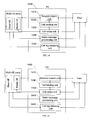
FIG. 1 is a flowchart of a call transfer method in a session between multiple UEs and a peer in the prior art; -
FIG. 2 is a flowchart of a multimedia session call control method in a first embodiment of the present invention; -
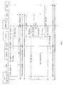
FIG. 3 is a signaling flowchart of a multimedia session call control method in a second embodiment of the present invention; -
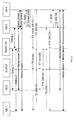
FIG. 4 is a signaling flowchart of a multimedia session call control method in a third embodiment of the present invention; -
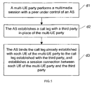
FIG. 5 is a flowchart of a multimedia session call control method in a fourth embodiment of the present invention; -
FIG. 6 is a signaling flowchart of a multimedia session call control method in a fifth embodiment of the present invention; -
FIG. 7 is a signaling flowchart of a multimedia session call control method in a sixth embodiment of the present invention; -
FIG. 8 is a signaling flowchart of a multimedia session call control method in a seventh embodiment of the present invention; -
FIG. 9 is a signaling flowchart of a multimedia session call control method in an eighth embodiment of the present invention; -
FIG. 10 is a signaling flowchart of a multimedia session call control method in a ninth embodiment of the present invention; -
FIG. 11 is a signaling flowchart of a multimedia session call control method in a tenth embodiment of the present invention; -
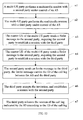
FIG. 12 is a flowchart of a multimedia session call control method in an eleventh embodiment of the present invention; -
FIG. 13 is a signaling flowchart of the eleventh embodiment of the present invention; -
FIG. 14 shows a structure of an AS in a twelfth embodiment of the present invention; and -
FIG. 15 shows a structure of an AS in a thirteenth embodiment of the present invention. - A multimedia session call control method is provided in various embodiments of the present invention to simplify the call transfer process, to shorten the call transfer time and to improve efficiency. The multimedia session call control method under the present invention is detailed below.
- A multimedia session call control method is provided. As shown in
FIG. 2 , the method includes the following steps: - a1. A multi-UE party performs a multimedia session with a peer under control of an AS.
- In this embodiment, the multi-UE party may perform a session with the peer under control of the AS according to the prior art. The AS is an MMSC AS or another AS with the B2BUA functions.
- a2. The master UE of the multi-UE party establishes a session with a third party under control of the AS.
- It is understandable that the master UE may be differentiated from the slave UE in many ways. For example, at the time of subscription, a UE is specified as a master UE and other UEs are specified as slave UEs; or, at the time of establishing the multimedia session, the UE that joins the session first is the master UE, and the UEs that join the session later are slave UEs; or, the AS may select a random PS access terminal as a master UE. The UE control capabilities may be allocated in multiple modes, which do not constitute limitations to the present invention.
- Nevertheless, the master UE in the present invention is generally a PS UE. Currently, the Media Gateway Control Function (MGCF) for signaling conversion between the Circuit Switched (CS) domain and the PS domain is unable to convert certain control signaling. Therefore, the CS UE is currently not suitable for acting as a master UE. With the improvement of the MGCF in the future, it is practicable to use the CS UE as a master UE. The major concern is that the AS can differentiate the master UE from the slave UE in multiple modes according to preset rules. The specific differentiation modes do not constitute limitations to the present invention.
- It is understandable that the session established between the master UE and the third party may be initiated by the master UE or the third party. The third party may be a UE, or an access network that covers the UE, or a server, for example, a conference center.
- If the session is initiated by the master UE, the process of establishing a session between the AS and the third party may include the following steps:
- The master UE and the AS send an Invite message carrying the address of the third party;
- The AS acts as a B2BUA, terminates the session, and regenerates an Invite message and sends it to the third party;
- The third party receives the Invite message, and returns a 200 OK message to accept the invitation;
- The AS receives the 200 OK message, and a call leg is established between the AS and the third party. The AS sends a 200 OK message to the third party, and a call leg is established between the AS and the master UE.
- In the whole call establishment process, the AS acts as a B2BUA to maintain the signaling connection with the master UE and the third party, and bind the call leg between the AS and the master UE to the call leg between the master UE and the third party. "Bind" refers to maintaining the trigger relation of the signaling sent by both parties. For example, if receiving an Invite message from the master UE that invites the third party to join a session, the AS generates a new Invite message and sends it to the third party; if receiving a 200 OK message returned by the third party, the AS sends the 200 OK message to the master UE. The process is known as "anchoring".
- The third party may be a UE, or an access network that covers the UE, or a server such as a conference center.
- a3. The AS binds the call leg between the slave UE of the multi-UE party and the AS to the session established with the third party.
- After step a3, the AS binds the call leg trigger relation between the slave UE of the multi-UE party and the AS to the call leg between the AS and the third party. The multi-UE party and the third party can update the media information of the peer reciprocally through the bound call leg, negotiate the media information between the master UE and the third party, and establish a connection of the media streams at the media layer.
- It is understandable that the UEs of the multi-UE party include PS UEs and CS UEs.
- If the slave UE of the multi-UE party is a CS UE, the PS UE is the master UE because the CS UE is unable to receive the Refer message from the AS.
- The process of updating the PS UE media information is implemented through the MGCF, as detailed below:
- The MGCF performs media negotiation with the third party in place of the CS UE of the multi-UE party.
- After completion of the negotiation, the CS UE of the multi-UE party establishes a media connection with the third party according to the negotiated media information.
- In this embodiment, the call transfer may be initiated by the peer. That is, before step a2, the AS receives a Refer message from the peer, and sends the Refer message to the multi-UE party, where the Refer message carries the address of the third party of the call transfer.
- It is understandable that the multi-UE party may be notified of call transfer initiated by the peer through a Refer message or a Notify message. The major concern herein is the content carried in the message, and the specific message name and the message format do not constitute any limitation to the present invention.
- Afterward, the multi-UE party may establish a session with the third party according to the third-party address obtained from the Refer message.
- The AS may send the Refer message to the multi-UE party in this way: Through the PS call leg between the AS and the multi-UE party, the Refer message is sent to the master UE of the multi-UE party. In the prior art, when the AS receives the Refer message from the peer, the Refer message is split into two Refer messages, which are sent to the PS UE and the CS UE of the multi-UE party respectively. In fact, the Refer message sent to the CS UE in the prior art fails to reach the destination. After this Refer message arrives at the MGCF, the MGCF is unable to interpret it, and hence reports error information to the AS. By comparison. In the embodiments of the present invention, the call transfer message is sent to the master UE of the multi-UE party directly, where the master UE is a PS UE. Compared with the prior art, this embodiment simplifies the signaling, removes the redundant signaling flow, and makes the technical solution under the present invention simpler and more appropriate.
- After the AS sends the Refer message to the multi-UE party, the method further includes:
- If the multi-UE party returns an acknowledgement of the Notify message to the AS, the AS releases the call leg between the AS and the peer; and the AS releases the call leg between the AS and the master UE of the multi-UE party.
- According to the first embodiment of the present invention, in the multimedia session established between the multi-UE party and the third party, part of the existing call legs are reused. By contrast, in the prior art, a multimedia session needs to be reconstructed to implement call transfer. Therefore, the embodiments of the present invention simplify the signaling flow of call transfer, shorten the call transfer time, and improve the system processing efficiency.
- It is understandable to those skilled in the art that all or part of the steps of the foregoing embodiment may be implemented by hardware instructed by a program. The program may be stored in a computer-readable storage medium. When being executed, the program performs at least the following steps:
- The multi-UE party performs a multimedia session with a peer under control of an AS.
- A master UE of the multi-UE party establishes a session with a third party under control of the AS.
- The AS binds a call leg between a slave UE of the multi-UE party and the peer to the session established with the third party.
- The storage medium may be a Read-Only Memory (ROM), a magnetic disk, or a compact disk.
- If the third party in the first embodiment of the present invention is a conference center, the method comes in two scenarios. The first scenario is:
- The peer interacts with the conference center to establish a conference.
- The peer sends a Refer message to the conference center, where the Refer message carries the address of the multi-UE party and the ID of the call leg between the AS and the peer.
- Step a2 includes:
- The conference center sends an Invite message to the AS, where the Invite message carries the address of the multi-UE party and the ID of the call leg.
- The AS modifies the ID of the call leg in the Invite message to the ID of the call leg between the AS and the master UE of the multi-UE party, and sends the modified Invite message to the master UE;
- The master UE accepts the invitation, and returns an OK message to the AS, and the AS returns the OK message to the conference center.
- The master UE releases the call leg indicated by the received call leg ID.
- The second scenario is specific to the conference initiated by the multi-UE party.
- The master UE of the multi-UE party sends a Refer message to the conference center. The Refer message carries the address of the peer and the ID of the call leg between the master UE and the AS, and is routed to the AS.
- The AS modifies the ID of the call leg in the Refer message to the ID of the call leg between the AS and the peer, and sends the Refer message to the conference center.
- The conference center sends an Invite message to the peer, where the Invite message carries the ID of the call leg between the AS and the peer.
- The peer returns an OK message to accept the invitation.
- The peer releases the session of the call leg indicated by the ID of the call leg between the AS and the peer.
- In the first scenario and the second scenario described above, a conference is established through interaction between the peer and the conference center, and the conference center invites the multi-UE party to the conference. Therefore, after the multi-UE party and the peer join the conference, the multi-UE party may talk with the peer through the conference. Disconnecting the call between the multi-UE party and the peer may release more resources and reduce the network load.
- As described above, in the case that the third party is a conference center, the AS modifies the call leg ID, and disconnects the call between the multi-UE party and the peer after the multi-UE party and the peer join the conference.
- It is understandable that the modification of the call leg ID is also applicable to the following scenarios:
- Before the master UE of the multi-UE party establishes a session with the third party under control of the AS:
- The peer sends a Refer message to the third party, where the Refer message carries the address of the multi-UE party and the ID of the call leg between the AS and the peer.
- The master UE of the multi-UE party establishes a session with the third party under control of the AS in the following way:
- The third party sends an Invite message to the AS, where the Invite message carries the address of the multi-UE party and the ID of the call leg.
- The AS modifies the ID of the call leg in the Invite message to the ID of the call leg between the AS and the master UE of the multi-UE party, and sends the modified Invite message to the master UE.
- The master UE accepts the invitation, and returns an OK message to the AS, and the AS returns the OK message to the third party.
- After the master UE of the multi-UE party establishes a session with the third party under control of the AS, the master UE releases the session of the call leg indicated by the received call leg ID, namely, releases the session between the master UE and the peer.
- A multimedia session call control method is provided in this embodiment. The signaling flow of the method is shown in
FIG. 3 . The method in the second embodiment applied in a specific scenario is detailed below: - In this embodiment, the multi-UE party uses a dual-mode UE capable of accessing a CS network and a PS network simultaneously. This UE is equivalent to a CS UE integrated with a PS UE.
- B1. UE-1 initiates an Invite message to UE-2 through an Establishment message in the CS network of a Universal Mobile Telecommunications System (UMTS). This message arrives at the visited Mobile Switching Center (vMSC) first.
- B2. The vMSC converts the message into an Initial Address Message (IAM), and sends it to the MGCF.
- B3. The MGCF converts the CS signaling into a Session Initiation Protocol (SIP) Invite message, and sends the message to the S-CSCF of UE-1.
- B4. The S-CSCF of UE-1 sends the message to the MMSC AS of UE-1 for anchoring.
- B5. UE-1 initiates an Invite message to UE-2 through the PS network of the UMTS. The Invite message arrives at the S-CSCF of UE-1 first, and the S-CSCF sends the message to the MMSC AS for anchoring.
Steps B1-B4 and step B5 may occur simultaneously, and are not sequence-sensitive. - B6. The MMSC AS integrates the PS calls and the CS calls of UE-1, and then sends the calls to UE-2 on the peer side.
Steps 1-6 complete the process of call establishment between UE-1 and UE-2. InFIG. 3 , the dotted line indicates the dialog relation;dialog 1 anddialog 2 are anchored at the MMSC AS; the dialog between the MMSC AS and UE-2 isdialog 3; and the solid line indicates the media stream transmission state after the session is established. - B7. UE-2 sends a Refer message to UE-1. The address of the Refer-To header of the message is the SIP Uniform Resource Identifier (URI) of UE-3, and the Refer message arrives at the MMSC AS first.
UE-2 transfers the multimedia session between UE-2 and UE-1 to UE-3. That is, an ECT supplementary service is implemented. The ECT is implemented through a SIP Refer message. - B8. After receiving the Refer message, the MMSC AS splits the media, and sends the Refer message to UE-1 through the leg in the PS domain.
- B9. UE-1 returns a 202 OK message from the PS leg.
- B10. According to the anchoring information, the MMSC AS generates a new 202 OK message and sends it to UE-2.
- B11. After receiving the OK message, UE-2 sends a BYE message to UE-1. The BYE message arrives at the MMSC AS first.
- B12. According to the anchoring information, the MMSC AS splits the BYE message, and sends the BYE message to the PS leg of UE-1.
- B13. UE-1 initiates an Invite message to UE-3 from the PS leg. The Invite message arrives at the MMSC AS through the S-CSCF.
- B14. After receiving the Invite message, the MMSC AS generates new anchoring information. Under control of the MMSC AS, the old CS signaling leg is added to the new anchoring information, and the PS media information of UE-1 and the media information of the Media Gateway (MGW) are integrated and then sent to UE-3.
- B 15. UE-3 returns a 200 OK message. This message carries media information, namely, IP address and port number, of UE-3.
- B16. According to the anchoring information, the MMSC AS sends the 200 OK message to UE-1.
- B17. The MMSC AS sends a re-Invite/Update message to the MGCF. This message carries UE-3 media information and instructs the MGW to establish a media connection with UE-3.
- In this embodiment, the PS part may be separated from the CS part of UE-1 to form two UEs, which does not affect the implementation of the method in this embodiment.
- A multimedia session call control method is provided in this embodiment. The signaling flow of the method is shown in
FIG. 4 . The method in the third embodiment applied in a specific scenario is detailed below: - In this embodiment, the multi-UE party is composed of two PS UEs. It is understandable that the multi-UE party may be composed of more UEs. The number of UEs of the multiple-UE party does not constitute any limitation to the present invention.
- C1. UE-1 initiates an Invite message to UE-3. Through the S-CSCF, the Invite message arrives at the MMSC AS for anchoring. The Invite message carries three types of media: voice, video, and text.
- C2. The MMSC AS generates a new Invite message and sends it to UE-2.
- C3. UE-1 decides to transfer the second channel of media to UE-2. UE-2 initiates an Invite message to the AS. The Session Description Protocol (SDP) media line information of the Invite message is "video". The MMSC AS anchors the Invite message, and adds the Invite message to the multimedia session between UE-1 and UE-3.
- C4. The MMSC AS sends an Update message to UE-3, instructing UE-3 to connect the second channel of media to UE-2.
Note 1: Steps 1-4 implement multimedia connections between UE-1, UE-2, and UE-3. InFIG. 4 , the dotted line indicates the dialog relation;dialog 1 anddialog 2 are anchored at the MMSC AS; and the dialog between the MMSC AS and UE-3 isdialog 3.
In this embodiment, UE-1 is a master UE, and UE-2 is a slave UE. UE-3 transfers the multimedia session between UE-3 and UE-1 as well as the multimedia session between UE-3 and UE-2 to UE-4. That is, an ECT supplementary service is implemented. The ECT is implemented through a SIP Refer message. - C5. UE-3 sends a Refer message. The address of the Refer-To header of the message is the SIP URI of UE-4, and the Refer message arrives at the MMSC AS first.
- C6. After receiving the Refer message, the MMSC AS splits the media, and sends the Refer message only to UE-1.
- C7. UE-1 returns a 202 OK message.
- C8. According to the anchoring information, the MMSC AS generates a new 202 OK message and sends it to UE-3.
- C9. After receiving the OK message, UE-3 sends a BYE message. The BYE message arrives at the MMSC AS first.
- C10. According to the anchoring information, the MMSC AS splits the BYE message, and sends the BYE message to UE-1.
- C11. UE-1 sends a new Invite message to UE-4. This message arrives at the MMSC AS through the S-CSCF.
- C12. After receiving the Invite message, the MMSC AS generates new anchoring information. Under control of the MMSC AS, the signaling of UE-2 is added to the new anchoring information, and the media information of UE-1 and the media information of UE-2 are integrated and then sent to UE-4.
- C13. UE-4 returns a 200 OK message. This message carries media information, namely, IP address and port number, of UE-4.
- C14. The MMSC AS sends a 200 OK message to UE-1 according to the anchoring information. This message carries media information of UE-4.
- C15. The MMSC AS sends a re-Invite/Update message to UE-2. This message carries UE-4 media information and instructs UE-2 to connect to UE-4.
- The third embodiment differs from the second embodiment in that the two UEs of the multi-UE party in the third embodiment are PS UEs.
- It is understandable that in the second embodiment and the third embodiment of present invention, the third party may be a conference center, and that the multi-UE party may interact with the conference center to create a conference or join a conference.
- A multimedia session call control method is provided. As shown in
FIG. 5 , the method includes the following steps: - d1. The multi-UE party performs a multimedia session with the peer under control of the AS.
The multi-UE party may be composed of PS UEs and CS UEs, or composed of PS UEs only. A multi-UE party may include one or more UEs. - d2. The AS establishes a call leg with a third party in place of the multi-UE party.
The call leg established between the AS and the third party is initiated by the AS or the third party.
The third party may be a UE, or an access network that covers the UE, or a server such as a conference center. - d3. The AS binds the call leg already established with each UE of the multi-UE party to the call leg established with the third party, and establishes a session connection between each UE of the multi-UE party and the third party.
- In this embodiment, before step d2, the method may include the following steps: The AS receives the Refer message from the peer, where the Refer message carries the address of the third party of the call transfer; the AS sends the Refer message to the multi-UE party; if receiving an OK message returned from the multi-UE party, the AS sends the OK message to the peer; the peer receives the OK message and releases the call leg between the peer and the AS.
- The fourth embodiment differs from the first embodiment in that: In the multimedia session established between the multi-UE party and the third party, all of the existing call legs are reused, thus simplifying the signaling flow of call transfer, shortening the call transfer time, and improving the system processing efficiency.
- A multimedia session call control method is provided. The signaling flow is shown in
FIG. 6 . This embodiment supposes that the multimedia session between the local UE-1 and the peer UE-2 is established successfully; the session involves three types of media streams: voice, video, and text. The multi-UE party UE-1 uses a dual-mode UE capable of accessing the CS network and the PS network simultaneously. The voice streams are transmitted in the CS network of the UMTS, and the remaining two types of media streams are transmitted in the PS network of the UMTS. - In
FIG. 6 , the S-CSCF and the AS are network devices that serve UE-1.FIG. 6 does not illustrate the S-CSCF or the AS corresponding to UE-2 and UE-3. - The process of establishing a call between UE-1 and UE-2 is the same as steps 1-6 in the second embodiment. It is understandable that the specific process of establishing a call between UE-1 and UE-2 may be implemented in many ways based on the prior art, and does not constitute any limitation to the present invention.
- In this embodiment, UE-2 transfers the multimedia session between UE-2 and UE-1 to UE-3. That is, an ECT supplementary service is implemented. The ECT is implemented through a SIP Refer message.
- E1. UE-2 sends a Refer message to UE-1. The address of the Refer-To header of the message is the SIP URI of UE-3, and the Refer message arrives at the MMSC AS first.
- E2. The MMSC AS sends a notification message (for example, Notify, or Info) to UE-1. This message notifies UE-1 that the peer is expected to perform an ECT supplementary service.
- E3. If accepting the supplementary service, the peer returns an OK message. If the peer refuses the supplementary service, the conversation between UE-1 and UE-2 goes on, without subsequent steps.
- E4. The MMSC AS sends a 202 OK message to UE-2 in place of UE-1.
- E5. After receiving the OK message, UE-2 sends a BYE message to UE-1, thus cutting off the signaling and multimedia connection with UE-1.
- E6. The MMSC AS sends an Invite message to a third-party UE-3 in place of UE-1.
- E7. The third-party UE-3 returns a 200 OK message. This message carries media information, namely, IP address and port number, of UE-3.
- E8. The MMSC AS sends a re-Invite/Update message to the MGCF. This message carries UE-3 media information and instructs the MGW to establish a media connection with UE-3.
- E9. The MMSC AS sends a re-Invite/Update message to the PS leg of UE-1. This message carries UE-3 media information and instructs UE-1 to establish a media connection with UE-3.
- A multimedia session call control method is provided. The signaling flow of the method is shown in
FIG. 7 . The method in the sixth embodiment of the present invention applied in a specific scenario is detailed below. - In this embodiment, the multi-UE party is composed of two PS UEs. It is understandable that the multi-UE party may be composed of more UEs. The number of UEs of the multiple-UE party does not constitute any limitation to the present invention.
- The process of establishing a call between UE-1 and UE-2 is the same as steps 1-4 in the third embodiment. It is understandable that the specific process of establishing a call between UE-1 and UE-2 may be implemented in many ways based on the prior art, and does not constitute any limitation to the present invention.
- In this embodiment, UE-3 transfers the multimedia session between UE-3 and UE-1 and the multimedia session between UE-3 and UE-2 to UE-4. That is, an ECT supplementary service is implemented. The ECT is implemented through a SIP Refer message.
- F1. UE-3 sends a Refer message. The address of the Refer-To header of the message is the SIP URI of UE-4; the Replace header of the message is the dialog ID of the dialog between UE-3 and UE-4; and the Refer message arrives at the MMSC AS first.
- F2. The MMSC AS sends a notification message (for example, Notify, or Info) to UE-1. This message notifies UE-1 that the peer is expected to perform an ECT supplementary service.
- F3. If accepting the supplementary service, the peer returns an OK message, and proceeds to step F4. If refusing the supplementary service, the peer goes on with the existing multimedia session, without performing the subsequent steps.
- F4. The MMSC AS returns a 202 OK message in place of UE-1 and UE-2.
- F5. The MMSC AS initiates an Invite message to UE-4 in place of UE-1 and UE-2. This message carries media information, namely, IP address and port number, of UE-1 and UE-2.
- F6. UE-4 returns a 200 OK message. This message carries media information, namely, IP address and port number, of UE-4.
- F7-F8. The MMSC AS sends a re-Invite/Update message to UE-1 and UE-2 respectively according to the anchoring information. This message carries UE-4 media information.
- F9. After establishing a call with UE-1 and UE-2 successfully, UE-4 sends a BYE message to UE-3.
- F10. UE-3 sends a BYE message, and the MMSC AS terminates the BYE message.
- The scenario in which the third party is a conference center is detailed below.
- A multimedia session call control method is provided. The signaling flow of the method is shown in
FIG. 8 . In this embodiment, the multi-UE party is UE-1; UE-1 is a dual-mode UE; the PS part of the UE may access the PS domain, and the CS part may access the CS domain. It is understandable that the multi-UE party may be a conference center. - This embodiment supposes that a multimedia session is already established between the multi-UE party (UE-1) and the peer (UE-2). This session involves two types of media streams: voice, and video. The voice streams are transmitted in the CS network, and the video streams are transmitted in the PS network.
- In
FIG. 8 , the S-CSCF and the AS are network devices that serve UE-1.FIG. 8 does not illustrate the S-CSCF or the AS corresponding to UE-2. - The process of establishing a call between UE-1 and UE-2 in this embodiment is the same as steps A1-A6 in the second embodiment.
- G1. UE-2 sends an Invite message to the conference center of the conference server. The destination address of the Invite message is a URI of the conference server.
- G2. The conference server generates a new focus for the newly created conference, allocates a conference URI (Conf URI) for the new conference, and adds the Conf URI to a 200 OK message, which is then returned to UE-2.
After steps G1-G2, the connection between UE-2 and the conference center is established successfully. - G3. UE-2 sends a Refer message to the conference center. The address of the Refer-To header of the message is the SIP URI of UE-1, and the Replace header of the message is the ID of the call leg between UE-2 and the MMSC AS. In this embodiment, the Replace header is the dialog ID of
dialog 3. - G4. The conference center sends an Invite message to UE-1. The Replace header of the Invite message is the dialog ID of
dialog 3 between UE-2 and the MMSC AS. The Contact header of the message is the URI of the conference center, and carries an isfocus parameter. The isfocus parameter indicates that the URI carried in this message is the URI of the conference center. - G5. After receiving the Invite message from the third party (MGCF), the MMSC AS generates new anchoring information and exercises control to add the old CS signaling leg to the new anchoring information. The MMSC AS splits the media, and sends an Invite message to the PS leg of UE-1. According to the anchoring information, the MMSC AS modifies the Replace header of the Invite message in
step 4 to the dialog ID ofdialog 2 between the PS domain of UE-1 and the MMSC AS, and adds the Replace header to the Invite message, which is then sent to UE-1. - G6. The MMSC AS sends a re-Invite message to the CS leg of UE-1. This message carries the media information of the conference center.
- G7. The MMSC AS returns a 200 OK message to the conference center. The message carries the integrated PS media information of UE-1 and the media information of the MGW.
- G8. UE-1 sends a BYE message to UE-2.
- G9. The MMSC AS sends a BYE message to UE-2 to release the session between UE-1 and UE-2.
- A multimedia session call control method is provided. The signaling flow of the method is shown in
FIG. 9 . In this embodiment, the multi-UE party is UE-1; UE-1 is a dual-mode UE; the PS part of the UE may access the PS domain, and the CS part may access the CS domain. It is understandable that the multi-UE party may be a conference center. - This embodiment supposes that a multimedia session is already established between the multi-UE party (UE-1) and the peer (UE-2). This session involves two types of media streams: voice, and video. The voice streams are transmitted in the CS network, and the video streams are transmitted in the PS network.
- In
FIG. 9 , the S-CSCF and the AS are network devices that serve UE-1.FIG. 9 does not illustrate the S-CSCF or the AS corresponding to UE-2. - The process of establishing a call between UE-1 and UE-2 in this embodiment is the same as steps A1-A6 in the second embodiment.
- H1. UE-2 sends an Invite message to the conference center of the conference server. The destination address of the Invite message is a URI of the conference server.
- H2. The conference server generates a new focus for the newly created conference, allocates a Conf URI for the new conference, and adds the Conf URI to a 200 OK message, which is then returned to UE-2.
- After steps H1-H2, the connection between UE-2 and the conference center is established successfully.
- H3. UE-2 sends a Refer message to the conference center. The address of the Refer-To header of the message is the SIP URI of UE-1, and the Replace header of the message is the dialog ID of the dialog between the MMSC AS and UE-2.
- H4. The conference center sends an Invite message to UE-1. The Replace header of the Invite message is the dialog ID of the dialog between UE-2 and the MMSC AS. The Contact header of the message is the URI of the conference center, and carries an isfocus parameter. The isfocus parameter indicates that the URI carried in this message is the URI of the conference center.
- H5. The MMSC AS sends a notification message (for example, Notify, or Info) to UE-1. This message notifies UE-1 that the third party is expected to perform a conference call.
- H6. If accepting the conference call, the peer returns an OK message. If refusing the conference call, the peer goes on with the existing multimedia session, without performing the subsequent steps.
- H7. The MMSC AS splits the media according to the anchoring information, and sends a re-Invite message to the PS leg of UE-1. This message carries the media information of the conference center.
- H8. The MMSC AS sends a re-Invite message to the CS leg of UE-1. This message carries the media information of the conference center.
- H9. The MMSC AS returns a 200 OK message to the conference center. The message carries the PS media information of UE-1 and the media information of the MGW.
- H10. The MMSC AS sends a BYE message to UE-2 in place of UE-1.
- A multimedia session call control method is provided. The signaling flow is shown in
FIG. 10 . In this embodiment, the multi-UE party is composed of two PS UEs: UE-1 and UE-2. - This embodiment supposes that a multimedia session is already established between UE-1 and UE-2. This session involves two types of media streams: voice, and video. The voice streams are transmitted in the CS network, and the video streams are transmitted in the PS network.
- In
FIG. 10 , the S-CSCF and the AS are network devices that serve UE-1.FIG. 10 does not illustrate the S-CSCF or the AS corresponding to UE-2 and UE-3. - The process of establishing a call between UE-1 and UE-2 in this embodiment is the same as steps C1-C4 in the third embodiment.
- S1. UE-1 sends an Invite message to the conference center of the conference server. The destination address of the Invite message is a URI of the conference server.
- S2. The MMSC AS generates new anchoring information for the message. Under control of the MMSC AS, the signaling of UE-2 is added to the new anchoring information, and the media information of UE-1 and the media information of UE-2 are integrated and then sent to the third party.
- S3. The conference server generates a new focus for the newly created conference, allocates a Conf URI for the new conference, and adds the Conf URI to a 200 OK message, which is then returned. The 200 OK message carries media information of the conference center.
- S4. According to the anchoring information, the MMSC AS sends the 200 OK message to UE-1.
- S5. The MMSC AS sends an Update message to UE-2, and sends the media information of the MREFP to UE-2.
After steps S1-S5, the connection between UE-1 and the conference center as well as the connection between UE-2 and the conference center are established successfully. - S6. UE-1 sends a Refer message to the conference center. The address of the Refer-To header of the message is the SIP URI of UE-3, and the Replace header of the message is the dialog ID of
dialog 2 between UE-1 and the MMSC AS. - S7. The MMSC AS generates a new Refer message, modifies the dialog ID of the dialog between UE-1 and the MMSC AS in the Replace header to the dialog ID of
dialog 3 between the MMSC AS and UE-3, and sends the new Refer message to the conference center. - S8. According to the Refer message, the conference center sends a new Invite message to UE-3. The Replace header of the Invite message is the dialog ID of
dialog 3 between UE-3 and the MMSC AS. The Contact header of the message is the URI of the conference center, and carries an isfocus parameter. The message carries media information of the conference center. - S9. UE-3 returns a 200 OK message. This message carries media information of UE-3.
Afterstep 9, the link between UE-3 and the conference center is established successfully. - S10. UE-3 sends a BYE message.
-
S 11. The MMSC AS sends a BYE message to UE-1. - A call control method is provided. The signaling flow is shown in
FIG. 11 . This embodiment supposes that UE-1 and UE-2 are two UEs of the multi-UE party; UE-1 and UE-2 are connected to UE-3 in a session; and UE-3 is connected to UE-4 in a session. - In
FIG. 11 , the S-CSCF and the AS are network devices that serve UE-1.FIG. 11 does not illustrate the S-CSCF or the AS corresponding to UE-2 and UE-3. - T1. UE-3 sends a Refer message to UE-4. The address of the Refer-To header of the message is the SIP URI of UE-1, and the Replace header of the message is the dialog ID of
dialog 3 between UE-3 and the MMSC AS. - T2. UE-4 returns an OK message to UE-3.
- T3. UE-4 sends an Invite message to UE-1. The Replace header of the Invite message is the dialog ID of
dialog 3 between UE-2 and the MMSC AS. - T4. After receiving the Invite message, the MMSC AS exercises control to bind the existing signaling leg between UE-2 and the MMSC AS to the signaling leg established in this step. The MMSC AS splits the media, and sends an Invite message to UE-1. The MMSC AS modifies the Replace header of the Invite message in
step 3 to the dialog ID ofdialog 2 between UE-1 and the MMSC AS, and adds the Replace header to the Invite message, which is then sent to UE-1. - T5. UE-1 returns an OK message.
- T6. The MMSC AS returns an OK message to UE-4.
- T7. The MMSC AS sends a re-Invite message to UE-2. This message carries the media information of UE-4.
- T8. UE-2 returns an OK message.
- T9. UE-1 sends a BYE message to UE-3.
- T10. UE-3 returns an OK message.
- T11-T12. UE-3 is disconnected from UE-4.
- A multimedia session call control method is provided. As shown in
FIG. 12 , the method includes: - n1. The multi-UE party performs a multimedia session with the second party under control of the AS.
- n2. The multi-UE party performs a multimedia session with the third party under control of the AS.
- n3. The master UE of the multi-UE party sends a Refer message to the second party, where the Refer message requires the second party to establish a session with the third party, carries an ID of a call leg between the master UE and the AS, and is routed to the AS.
- n4. The AS modifies the ID of the call leg in the Refer message to the ID of the call leg between the AS and the third party, and sends the Refer message to the second party.
- n5. The second party sends an Invite message to the third party, where the Invite message carries the ID of the call leg between the AS and the third party.
- n6. The third party accepts the invitation, and establishes a session with the second party.
- n7. The third party releases the session of the call leg indicated by the ID according to the ID of the call leg.
- In the eleventh embodiment of the present invention, the AS differentiates the master UE from the slave UE of the multi-UE party. In the call transfer process, after a Refer message is received from the second party, the ID of the call leg between the AS and the second party is modified to the ID of the master UE. Therefore, the multi-UE party can identify the session that needs to be released after the call transfer, and the ECT service supports multiple UEs and is applicable in a wider scope.
- Described below is a signaling flow of the eleventh embodiment applied in a specific scenario. As shown in
FIG. 13 , the signaling flow includes: - M1. UE-1 sends a Refer message to UE-3. The address of the Refer-To header of the message is the SIP URI of UE-4, and the Replace header of the message is the dialog ID of
dialog 2 between UE-1 and the MMSC AS. - M2. The MMSC AS generates a new Refer message, modifies the dialog ID of the dialog between UE-1 and the MMSC AS in the Replace header to the dialog ID of
dialog 3 between the MMSC AS and UE-4, and sends the new Refer message to UE-3. - M3. UE-3 returns an OK message.
- M4. UE-3 sends a new Invite message to UE-3 according to the foregoing Refer message. The Replace header of the new Invite message is the dialog ID of
dialog 3 between UE-4 and the MMSC AS. - M5. UE-4 returns a 200 OK message. This message carries media information of UE-4.
After step M5, the link between UE-4 and UE-3 is established successfully. - M6. UE-4 sends a BYE message to the MMSC AS to cut off the connection between UE-4 and UE-1, and the connection between UE-4 and UE-2.
- M7-M8. The MMSC AS splits the message, and sends a BYE message to UE-1 and UE-2 respectively.
- M9. UE-1 sends a BYE message to UE-4.
- M10-M11. The MMSC AS splits the message in
step 9, and sends a BYE message to UE-4 and UE-2 respectively to cut off the connection between UE-1 and UE-4, and the connection between UE-2 and UE-4. - An AS 1300 is provided. As shown in
FIG. 14 , theAS 1300 includes: asession control unit 1310, configured to control the multi-UE party to perform a multimedia session with the peer; acall establishment unit 1320, configured to control the master UE of the multi-UE party to establish a session with a third party; acall binding unit 1330, configured to bind the call leg between the slave UE of the multi-UE party and the peer to the session established with the third party; a Refermessage processing unit 1340, configured to receive a Refer message from the peer, and send the Refer message to the multi-UE party, the Refer message carrying the address of the third party of the call transfer; and a callleg releasing unit 1350, configured to receive the call transfer acknowledgement from the multi-UE party, and therefore, release the call leg between the AS and the peer; and release the call leg between the AS and the master UE of the multi-UE party. - An AS 1400 is provided. As shown in
FIG. 15 , theAS 1400 includes: asession control unit 1410, configured to control the multi-UE party to perform a multimedia session with the peer; acall establishment unit 1420, configured to establish a call leg with a third party in place of the multi-UE party; acall binding unit 1430, configured to bind the call leg already established with each UE of the multi-UE party to the call leg established with the third party, and establish a session connection between each UE of the multi-UE party and the third party; a Refermessage processing unit 1440, configured to receive a Refer message from the peer, and notify the multi-UE party that the peer requests call transfer, the Refer message carrying the address of the third party of the call transfer; and a callleg releasing unit 1450, configured to release the call leg between the AS and the peer after receiving an OK message from the multi-UE party in response to the notification. - Detailed above are a multimedia session call control method and an AS under the present invention.
- According to the embodiments of the present invention, in the multimedia session established between the multi-UE party and the third party, all or part of the existing call legs are reused. By contrast, in the prior art, a multimedia session needs to be reconstructed to implement call transfer. Therefore, the embodiments of the present invention simplify the signaling flow of call transfer, shorten the call transfer time, improve the system processing efficiency, and enhance the user experience.
- By comparison, in the embodiments of the present invention, the call transfer message is sent to the master UE of the multi-UE party directly, where the master UE is a PS UE. Compared with the prior art, this embodiment simplifies the signaling, removes the redundant signaling flow, and makes the technical solution under the present invention simpler and more appropriate.
- Although the invention is described through some exemplary embodiments, the invention is not limited to such embodiments. It is apparent that those skilled in the art can make various modifications and variations to the invention without departing from the scope of the invention defined by the appended claims.
Claims (13)
- A multimedia session call control method, comprising:performing (a1), by a multi-User Equipment UE party (UE1, UE2), a multimedia session with a peer (UE3) under control of an Application Server AS, characterized by:establishing (a2), by a master UE (UE1) of the multi-UE party (UE1, UE2), a session with a third party (UE4) under control of the AS; andbinding (a3), by the AS, a call leg between a slave UE (UE2) of the multi-UE party (UE1, UE2) and the AS to the session established with the third party (UE4).
- The method of claim 1, wherein before the master UE (UE1) of the multi-UE party (UE1, UE2)establishes the session with the third party (UE4) under control of the AS, the method further comprises:receiving, by the AS, a Refer message from the peer (UE3), and sending the Refer message to the master UE (UE1) of the multi-UE party (UE1, UE2), the Refer message carrying an address of the third party (UE4).
- The method of claim 2, wherein the process of sending the Refer message to the master UE (UE1) of the multi-UE party (UE1, UE2) comprises:sending the Refer message to the master UE (UE1) of the multi-UE party (UE1, UE2) through a Packet Switched PS call leg between the AS and the multi-UE party (UE1, UE2).
- The method of claim 2, wherein after the AS sends the Refer message to the master UE (UE1) of the multi-UE party (UE1, UE2), the method further comprises:releasing the call leg between the AS and the peer (UE3), and releasing the call leg between the AS and the master UE (UE1) of the multi-UE party (UE1, UE2) if the master UE (UE1) of the multi-UE party (UE I, UE2) returns an acknowledgement message of the call transfer to the AS.
- The method of claim 1, wherein the session established by the master UE (UE1) of the multi-UE party (UE1, UE2) with the third party under control of the AS is initiated by the master UE (UE1) or the third party (UE4).
- The method of claim 5, wherein the third party (UE4) is a conference center.
- The method of claim 1, wherein before the master UE (UE1) of the multi-UE party (UE1, UE2) establishes the session with the third party (UE4) under control of the AS, the method further comprises:sending, by the peer (UE3), a Refer message to the third party (UE4), wherein the Refer message carries an address of the multi-UE party (UE1, UE2) and an ID of the call leg between the AS and the peer(UE3).
- The method of claim 7, wherein the process of establishing the session with the third party (UE4) under control of the AS by the master UE (UE1) of the multi-UE party (UE1, UE2)comprises:sending, by the third party (UE4), an Invite message to the AS, wherein the Invite message carries the address of the multi-UE party (UE1, UE2) and the ID of the call leg;modifying, by the AS, the ID of the call leg in the Invite message to the ID of the call leg between the AS and the multi-UE party (UE1, UE2), and sending the modified Invite message to the master UE (UE1); andaccepting, by the master UE (UE1), the invitation, and returning an OK message to the AS; and, returning, by the AS, the OK message to the third party (UE4).
- The method of claim 8, wherein after the master UE (UE1) of the multi-UE party (UE1, UE2) establishes the session with the third party (UE4) under control of the AS, the method further comprises:releasing, by the master UE (UE1), the session of the call leg indicated by the received ID of the call leg.
- The method of claim 1, wherein after the AS binds the call leg between the slave UE (UE2) of the multi-UE party (UE1, UE2) and the AS to the session established with the third party (UE4), the method further comprises:sending, by the AS, an Update message through the call leg between the slave UE (UE2) and the AS, wherein the Update message is configured to establish a media connection between the slave UE (UE2) and the third party (UE4).
- An Application Server AS, comprising:a session control unit (1310), configured to control a multi-User Equipment UE party (UE1, UE2) to perform a multimedia session with a peer (UE3), characterized by:a call establishment unit (1320), configured to control a master UE (UE1) of the multi-UE party (UE1, UE2) to establish a session with a third party (UE4); anda call binding unit (1330), configured to bind a call leg between a slave UE (UE2) of the multi-UE party (UE1, UE2)and the peer (UE3) to the session established with the third party (UE4).
- The AS of claim 11, further comprising:a Refer message processing unit (1340), configured to receive a Refer message from the peer (UE3), and send the Refer message to the multi-UE party (UE1, UE2), the Refer message carrying an address of the third party (UE4) of call transfer.
- The AS of claim 12, further comprising: a call leg releasing unit (1350), configured to receive a call transfer acknowledgement from the multi-UE party (UE1, UE2), and therefore, release the call leg between the AS and the peer (UE3); and release the call leg between the AS and the master UE (UE1) of the multi-UE party (UE1, UE2).
Applications Claiming Priority (2)
| Application Number | Priority Date | Filing Date | Title |
|---|---|---|---|
| CN2007101657839A CN101431737B (en) | 2007-11-05 | 2007-11-05 | Multimedia conversation call control method and application server thereof |
| PCT/CN2008/072924 WO2009059559A1 (en) | 2007-11-05 | 2008-11-04 | A multimedia session call control method and the application server thereof |
Publications (3)
| Publication Number | Publication Date |
|---|---|
| EP2202934A1 EP2202934A1 (en) | 2010-06-30 |
| EP2202934A4 EP2202934A4 (en) | 2011-12-07 |
| EP2202934B1 true EP2202934B1 (en) | 2014-05-07 |
Family
ID=40625385
Family Applications (1)
| Application Number | Title | Priority Date | Filing Date |
|---|---|---|---|
| EP08846806.1A Not-in-force EP2202934B1 (en) | 2007-11-05 | 2008-11-04 | A multimedia session call control method and the application server thereof |
Country Status (6)
| Country | Link |
|---|---|
| US (2) | US9031057B2 (en) |
| EP (1) | EP2202934B1 (en) |
| JP (1) | JP5118204B2 (en) |
| KR (1) | KR101141125B1 (en) |
| CN (1) | CN101431737B (en) |
| WO (1) | WO2009059559A1 (en) |
Families Citing this family (32)
| Publication number | Priority date | Publication date | Assignee | Title |
|---|---|---|---|---|
| US8542802B2 (en) | 2007-02-15 | 2013-09-24 | Global Tel*Link Corporation | System and method for three-way call detection |
| CN101431737B (en) | 2007-11-05 | 2012-07-04 | 华为技术有限公司 | Multimedia conversation call control method and application server thereof |
| US9225838B2 (en) | 2009-02-12 | 2015-12-29 | Value-Added Communications, Inc. | System and method for detecting three-way call circumvention attempts |
| CN101883342B (en) * | 2009-05-05 | 2014-12-10 | 华为终端有限公司 | Session transferring method, device and system |
| CN101567797B (en) * | 2009-05-20 | 2013-02-27 | 中兴通讯股份有限公司 | Method and system for realizing transfer class service |
| CN101990181A (en) * | 2009-08-07 | 2011-03-23 | 华为终端有限公司 | Method for transmitting session information and device thereof |
| CN101662472B (en) * | 2009-09-16 | 2012-10-03 | 中兴通讯股份有限公司 | Method and system of realizing call forwarding employing set-top box based on SIP protocol |
| CN102075494B (en) * | 2009-11-20 | 2014-02-26 | 华为终端有限公司 | Method and device for establishing federated session |
| CN101827322B (en) | 2010-03-02 | 2013-02-13 | 华为终端有限公司 | Business control method and device |
| CN102299908B (en) * | 2010-06-24 | 2014-11-05 | 中兴通讯股份有限公司 | Method and system for realizing media switching among users |
| FR2964000A1 (en) * | 2010-08-17 | 2012-02-24 | France Telecom | COMMUNICATION TRANSFER PROCESSING IN SIP MODE. |
| US9602634B2 (en) * | 2012-02-15 | 2017-03-21 | Avaya Inc. | Global session identifier |
| CN103298047B (en) * | 2012-02-28 | 2015-11-25 | 鼎桥通信技术有限公司 | A kind of by the method for multiple user-association in same community and the network equipment |
| CN102647615B (en) * | 2012-03-15 | 2015-06-10 | 北京视博云科技有限公司 | Method, device and system for providing multimedia application data |
| US10110682B2 (en) * | 2012-03-23 | 2018-10-23 | Avaya Inc. | Supporting intermediate back to back user agents between user agents and a conference focus |
| US9544099B2 (en) * | 2012-07-02 | 2017-01-10 | Intel Corporation | User equipment, evolved node B, and method for multicast device-to-device communications |
| US8700019B2 (en) * | 2012-08-27 | 2014-04-15 | Avaya Inc. | Method and apparatus for dynamic device pairing |
| JP2014103614A (en) * | 2012-11-22 | 2014-06-05 | Hitachi Ltd | Communication system |
| US9148489B2 (en) | 2013-03-11 | 2015-09-29 | Qualcomm Incorporated | Exchanging a contact profile between client devices during a communication session |
| US9622275B2 (en) * | 2013-03-15 | 2017-04-11 | Qualcomm Incorporated | System and method for allowing multiple devices to communicate in a network |
| KR102199030B1 (en) * | 2014-02-22 | 2021-01-06 | 삼성전자주식회사 | Method for communicating with neighbor apparatus, electronic apparatus and storage medium |
| CN104883262A (en) * | 2014-02-28 | 2015-09-02 | 中兴通讯股份有限公司 | Multi-terminal communication method and apparatus |
| CN104935763B (en) * | 2014-03-20 | 2018-05-25 | 华为技术有限公司 | A kind of processing method of videoconference, hosting side's telephone terminal and TeleConference Bridge |
| CN105099987B (en) * | 2014-04-24 | 2018-06-26 | 华为技术有限公司 | Business access method, the apparatus and system of terminal |
| CN105530452A (en) * | 2014-10-24 | 2016-04-27 | 三亚中兴软件有限责任公司 | Processing method and device of conference terminal call forwarding |
| CN106034128B (en) * | 2015-03-18 | 2019-07-23 | 阿尔卡特朗讯 | It is a kind of for discharging the method and apparatus of the media in SIP session |
| US10193931B2 (en) | 2016-03-31 | 2019-01-29 | Avaya Inc. | Session initiation protocol call preservation based on a network failure |
| US10469538B2 (en) * | 2016-03-31 | 2019-11-05 | Avaya Inc. | Call preservation for multiple legs of a call when a primary session manager fails |
| DE112016007007T5 (en) | 2016-06-22 | 2019-03-07 | Intel Corporation | COMMUNICATION DEVICE AND METHOD FOR FULL DUPLEX DISPOSITION |
| US9614974B1 (en) * | 2016-11-23 | 2017-04-04 | Global Tel*Link Corp. | Utilizing sip messages to determine the status of a remote terminal in VoIP communication systems |
| US9930088B1 (en) | 2017-06-22 | 2018-03-27 | Global Tel*Link Corporation | Utilizing VoIP codec negotiation during a controlled environment call |
| CN119521150A (en) * | 2023-08-23 | 2025-02-25 | 上海玄戒技术有限公司 | Blind transfer method, device, communication equipment and chip |
Family Cites Families (30)
| Publication number | Priority date | Publication date | Assignee | Title |
|---|---|---|---|---|
| JPH1032652A (en) * | 1996-07-12 | 1998-02-03 | Ricoh Co Ltd | Multimedia communication system |
| US7684317B2 (en) * | 2001-06-14 | 2010-03-23 | Nortel Networks Limited | Protecting a network from unauthorized access |
| US20030059015A1 (en) * | 2001-09-21 | 2003-03-27 | Mello Eber | Call server allowing calls with multiple participants and multiple services independently of the number of participants |
| JP3767562B2 (en) * | 2002-06-21 | 2006-04-19 | 住友化学株式会社 | Method for producing ε-caprolactam |
| US20040001512A1 (en) * | 2002-06-28 | 2004-01-01 | International Business Machines Corporation | Method and apparatus for peer to peer bandwidth sharing |
| US7602704B2 (en) * | 2002-08-20 | 2009-10-13 | Cisco Technology, Inc. | System and method for providing fault tolerant IP services |
| WO2004075518A1 (en) * | 2003-02-19 | 2004-09-02 | National Institute Of Information And Communications Technology, Independent Administrative Agency | Communication node, signaling network, communication network system, and communication method thereof |
| US7898990B2 (en) * | 2003-03-25 | 2011-03-01 | Spyder Navigations L.L.C. | Method, system and gateway device for enabling interworking between IP and CS networks |
| WO2004107721A2 (en) * | 2003-05-29 | 2004-12-09 | Nimcat Networks Inc. | Call transfer and call pickup |
| GB0329707D0 (en) * | 2003-12-22 | 2004-01-28 | Nokia Corp | Activation of services in a communication system |
| EP1578152A1 (en) * | 2004-03-17 | 2005-09-21 | France Telecom | Method, Server and System to manage a "push-to-talk" session |
| EP1779625B1 (en) | 2004-07-30 | 2018-10-17 | CommScope Technologies LLC | A local network node |
| US20060083244A1 (en) * | 2004-10-15 | 2006-04-20 | Balakumar Jagadesan | Method for sessions including multiple resources |
| DE602005020845D1 (en) * | 2004-12-17 | 2010-06-02 | Nxp Bv | COMMUNICATION SYSTEM WITH PORTABLE MASTER AND SLAVE DEVICES |
| CN100544388C (en) * | 2005-07-01 | 2009-09-23 | 华为技术有限公司 | A method for controlling multiple forwarding and dialing of services |
| EP1959608A4 (en) * | 2005-12-03 | 2009-04-22 | Huawei Tech Co Ltd | A method, a application server and a system for implementing the third party control service |
| CN100433751C (en) * | 2005-12-03 | 2008-11-12 | 华为技术有限公司 | Method for realizing the third-part control bussiness |
| US9060047B2 (en) * | 2005-12-21 | 2015-06-16 | Genband Us Llc | Media stream management |
| CN101026616B (en) | 2006-02-18 | 2013-01-09 | 华为技术有限公司 | Multimedia subsystem based interactive media session establishing system and method |
| US7701971B2 (en) | 2006-02-27 | 2010-04-20 | Cisco Technology, Inc. | System and method for providing a compatibility feature in a session initiation protocol (SIP) environment |
| US8719342B2 (en) | 2006-04-25 | 2014-05-06 | Core Wireless Licensing, S.a.r.l. | Third-party session modification |
| WO2008009089A1 (en) * | 2006-07-21 | 2008-01-24 | Bce Inc | Method, system and apparatus for participant verification in a multi-party call environment |
| TWI430242B (en) * | 2006-08-01 | 2014-03-11 | Samsung Display Co Ltd | Display device and method of driving a display device |
| US20080141343A1 (en) * | 2006-08-16 | 2008-06-12 | Matsushita Electric Industrial Co., Ltd. | Method, system and apparatus for access control |
| US20090323656A1 (en) | 2006-10-04 | 2009-12-31 | Nortel Networks Limited | Circuit-switched and multimedia subsystem voice continuity |
| CN101192851A (en) * | 2006-11-28 | 2008-06-04 | 华为技术有限公司 | Method, system and application server for preventing ring tone crosstalk |
| US20080304451A1 (en) * | 2007-06-05 | 2008-12-11 | Lucent Technologies, Inc. | Method to allow hand-off of a cdma mobile from ims femtocell to circuit msc |
| US20090067408A1 (en) * | 2007-09-12 | 2009-03-12 | Nokia Corporation | Centralized call log and method thereof |
| US8103299B2 (en) * | 2007-09-25 | 2012-01-24 | Qualcomm Incorporated | Uni-directional traffic channel assignment for a receive-only group call in a mobile communication system |
| CN101431737B (en) | 2007-11-05 | 2012-07-04 | 华为技术有限公司 | Multimedia conversation call control method and application server thereof |
-
2007
- 2007-11-05 CN CN2007101657839A patent/CN101431737B/en active Active
-
2008
- 2008-11-04 JP JP2010531404A patent/JP5118204B2/en not_active Expired - Fee Related
- 2008-11-04 KR KR1020107010950A patent/KR101141125B1/en not_active Expired - Fee Related
- 2008-11-04 WO PCT/CN2008/072924 patent/WO2009059559A1/en not_active Ceased
- 2008-11-04 EP EP08846806.1A patent/EP2202934B1/en not_active Not-in-force
-
2010
- 2010-05-03 US US12/772,515 patent/US9031057B2/en active Active
-
2015
- 2015-05-11 US US14/708,818 patent/US10469545B2/en active Active
Also Published As
| Publication number | Publication date |
|---|---|
| JP5118204B2 (en) | 2013-01-16 |
| EP2202934A4 (en) | 2011-12-07 |
| JP2011502411A (en) | 2011-01-20 |
| US10469545B2 (en) | 2019-11-05 |
| KR20100076036A (en) | 2010-07-05 |
| CN101431737B (en) | 2012-07-04 |
| US20150244746A1 (en) | 2015-08-27 |
| WO2009059559A1 (en) | 2009-05-14 |
| US9031057B2 (en) | 2015-05-12 |
| CN101431737A (en) | 2009-05-13 |
| US20100215037A1 (en) | 2010-08-26 |
| EP2202934A1 (en) | 2010-06-30 |
| KR101141125B1 (en) | 2012-05-02 |
Similar Documents
| Publication | Publication Date | Title |
|---|---|---|
| US9031057B2 (en) | Multimedia session call control method and application server | |
| US8402154B2 (en) | Method, application server and user equipment for transferring media streams of multimedia session | |
| CA2672697C (en) | Session continuity in communication networks | |
| US8855104B2 (en) | Method for switching the session control path of IP multimedia core network subsystem centralized service | |
| US8825875B2 (en) | Session establishment in a communication network | |
| CN100563235C (en) | Interworking system and method for interworking function network element, CSI terminal and IMS terminal | |
| US20080285487A1 (en) | Method and system for providing full duplex services over multiple simplex media paths and sessions | |
| CN101674305B (en) | Method and system for realizing multimedia conference | |
| US10681100B2 (en) | Method, user equipment and application server for adding media stream of multimedia session | |
| EP2312806B1 (en) | A media negotiation method for ip multimedia link | |
| CN101835121A (en) | Method, system and device for carrying out adaptation processing on media negotiation | |
| CN101227647A (en) | A Handover Method for Maintaining Multimedia Session Continuity Service | |
| CN101924772A (en) | Communication system and method supporting cross-network and cross-terminal multimedia session merging | |
| CN103517463B (en) | Home gateway, audio communication method and device | |
| CN101527894A (en) | Method, equipment and mobile communication system for realizing explicit communication transfer | |
| CN101227728B (en) | Conversation combining method of multimedia conversation continuity business | |
| CN111404862B (en) | Multimedia processing method and equipment | |
| WO2009121310A1 (en) | Method, system and device for selecting a gateway | |
| WO2011015019A1 (en) | Method for implementing multi party call service continuity and system thereof | |
| CN102158923B (en) | Method and system for realizing single radio voice call continuity (SRVCC) | |
| CN101848194B (en) | Method, system, server and user equipment for transferring media | |
| EP2147525A1 (en) | Method and system for providing full duplex services over multiple simplex media paths and sessions | |
| HK1158423A1 (en) | Conveying session continuity information in a multi-component communication session |
Legal Events
| Date | Code | Title | Description |
|---|---|---|---|
| PUAI | Public reference made under article 153(3) epc to a published international application that has entered the european phase |
Free format text: ORIGINAL CODE: 0009012 |
|
| 17P | Request for examination filed |
Effective date: 20100505 |
|
| AK | Designated contracting states |
Kind code of ref document: A1 Designated state(s): AT BE BG CH CY CZ DE DK EE ES FI FR GB GR HR HU IE IS IT LI LT LU LV MC MT NL NO PL PT RO SE SI SK TR |
|
| AX | Request for extension of the european patent |
Extension state: AL BA MK RS |
|
| DAX | Request for extension of the european patent (deleted) | ||
| A4 | Supplementary search report drawn up and despatched |
Effective date: 20111109 |
|
| RIC1 | Information provided on ipc code assigned before grant |
Ipc: H04L 29/06 20060101AFI20111103BHEP |
|
| GRAP | Despatch of communication of intention to grant a patent |
Free format text: ORIGINAL CODE: EPIDOSNIGR1 |
|
| INTG | Intention to grant announced |
Effective date: 20131202 |
|
| GRAS | Grant fee paid |
Free format text: ORIGINAL CODE: EPIDOSNIGR3 |
|
| GRAA | (expected) grant |
Free format text: ORIGINAL CODE: 0009210 |
|
| AK | Designated contracting states |
Kind code of ref document: B1 Designated state(s): AT BE BG CH CY CZ DE DK EE ES FI FR GB GR HR HU IE IS IT LI LT LU LV MC MT NL NO PL PT RO SE SI SK TR |
|
| REG | Reference to a national code |
Ref country code: GB Ref legal event code: FG4D |
|
| REG | Reference to a national code |
Ref country code: AT Ref legal event code: REF Ref document number: 667418 Country of ref document: AT Kind code of ref document: T Effective date: 20140515 |
|
| REG | Reference to a national code |
Ref country code: IE Ref legal event code: FG4D |
|
| REG | Reference to a national code |
Ref country code: DE Ref legal event code: R096 Ref document number: 602008032166 Country of ref document: DE Effective date: 20140618 |
|
| REG | Reference to a national code |
Ref country code: NL Ref legal event code: T3 |
|
| REG | Reference to a national code |
Ref country code: AT Ref legal event code: MK05 Ref document number: 667418 Country of ref document: AT Kind code of ref document: T Effective date: 20140507 |
|
| REG | Reference to a national code |
Ref country code: LT Ref legal event code: MG4D |
|
| PG25 | Lapsed in a contracting state [announced via postgrant information from national office to epo] |
Ref country code: FI Free format text: LAPSE BECAUSE OF FAILURE TO SUBMIT A TRANSLATION OF THE DESCRIPTION OR TO PAY THE FEE WITHIN THE PRESCRIBED TIME-LIMIT Effective date: 20140507 Ref country code: CY Free format text: LAPSE BECAUSE OF FAILURE TO SUBMIT A TRANSLATION OF THE DESCRIPTION OR TO PAY THE FEE WITHIN THE PRESCRIBED TIME-LIMIT Effective date: 20140507 Ref country code: NO Free format text: LAPSE BECAUSE OF FAILURE TO SUBMIT A TRANSLATION OF THE DESCRIPTION OR TO PAY THE FEE WITHIN THE PRESCRIBED TIME-LIMIT Effective date: 20140807 Ref country code: GR Free format text: LAPSE BECAUSE OF FAILURE TO SUBMIT A TRANSLATION OF THE DESCRIPTION OR TO PAY THE FEE WITHIN THE PRESCRIBED TIME-LIMIT Effective date: 20140808 Ref country code: LT Free format text: LAPSE BECAUSE OF FAILURE TO SUBMIT A TRANSLATION OF THE DESCRIPTION OR TO PAY THE FEE WITHIN THE PRESCRIBED TIME-LIMIT Effective date: 20140507 Ref country code: IS Free format text: LAPSE BECAUSE OF FAILURE TO SUBMIT A TRANSLATION OF THE DESCRIPTION OR TO PAY THE FEE WITHIN THE PRESCRIBED TIME-LIMIT Effective date: 20140907 |
|
| PG25 | Lapsed in a contracting state [announced via postgrant information from national office to epo] |
Ref country code: AT Free format text: LAPSE BECAUSE OF FAILURE TO SUBMIT A TRANSLATION OF THE DESCRIPTION OR TO PAY THE FEE WITHIN THE PRESCRIBED TIME-LIMIT Effective date: 20140507 Ref country code: HR Free format text: LAPSE BECAUSE OF FAILURE TO SUBMIT A TRANSLATION OF THE DESCRIPTION OR TO PAY THE FEE WITHIN THE PRESCRIBED TIME-LIMIT Effective date: 20140507 Ref country code: ES Free format text: LAPSE BECAUSE OF FAILURE TO SUBMIT A TRANSLATION OF THE DESCRIPTION OR TO PAY THE FEE WITHIN THE PRESCRIBED TIME-LIMIT Effective date: 20140507 Ref country code: LV Free format text: LAPSE BECAUSE OF FAILURE TO SUBMIT A TRANSLATION OF THE DESCRIPTION OR TO PAY THE FEE WITHIN THE PRESCRIBED TIME-LIMIT Effective date: 20140507 Ref country code: PL Free format text: LAPSE BECAUSE OF FAILURE TO SUBMIT A TRANSLATION OF THE DESCRIPTION OR TO PAY THE FEE WITHIN THE PRESCRIBED TIME-LIMIT Effective date: 20140507 Ref country code: SE Free format text: LAPSE BECAUSE OF FAILURE TO SUBMIT A TRANSLATION OF THE DESCRIPTION OR TO PAY THE FEE WITHIN THE PRESCRIBED TIME-LIMIT Effective date: 20140507 |
|
| PG25 | Lapsed in a contracting state [announced via postgrant information from national office to epo] |
Ref country code: PT Free format text: LAPSE BECAUSE OF FAILURE TO SUBMIT A TRANSLATION OF THE DESCRIPTION OR TO PAY THE FEE WITHIN THE PRESCRIBED TIME-LIMIT Effective date: 20140908 |
|
| PG25 | Lapsed in a contracting state [announced via postgrant information from national office to epo] |
Ref country code: BE Free format text: LAPSE BECAUSE OF FAILURE TO SUBMIT A TRANSLATION OF THE DESCRIPTION OR TO PAY THE FEE WITHIN THE PRESCRIBED TIME-LIMIT Effective date: 20140507 Ref country code: CZ Free format text: LAPSE BECAUSE OF FAILURE TO SUBMIT A TRANSLATION OF THE DESCRIPTION OR TO PAY THE FEE WITHIN THE PRESCRIBED TIME-LIMIT Effective date: 20140507 Ref country code: SK Free format text: LAPSE BECAUSE OF FAILURE TO SUBMIT A TRANSLATION OF THE DESCRIPTION OR TO PAY THE FEE WITHIN THE PRESCRIBED TIME-LIMIT Effective date: 20140507 Ref country code: DK Free format text: LAPSE BECAUSE OF FAILURE TO SUBMIT A TRANSLATION OF THE DESCRIPTION OR TO PAY THE FEE WITHIN THE PRESCRIBED TIME-LIMIT Effective date: 20140507 Ref country code: RO Free format text: LAPSE BECAUSE OF FAILURE TO SUBMIT A TRANSLATION OF THE DESCRIPTION OR TO PAY THE FEE WITHIN THE PRESCRIBED TIME-LIMIT Effective date: 20140507 Ref country code: EE Free format text: LAPSE BECAUSE OF FAILURE TO SUBMIT A TRANSLATION OF THE DESCRIPTION OR TO PAY THE FEE WITHIN THE PRESCRIBED TIME-LIMIT Effective date: 20140507 |
|
| REG | Reference to a national code |
Ref country code: DE Ref legal event code: R026 Ref document number: 602008032166 Country of ref document: DE |
|
| PLBI | Opposition filed |
Free format text: ORIGINAL CODE: 0009260 |
|
| PLAX | Notice of opposition and request to file observation + time limit sent |
Free format text: ORIGINAL CODE: EPIDOSNOBS2 |
|
| 26 | Opposition filed |
Opponent name: JAMES POOLE LIMITED Effective date: 20150206 |
|
| PLAF | Information modified related to communication of a notice of opposition and request to file observations + time limit |
Free format text: ORIGINAL CODE: EPIDOSCOBS2 |
|
| REG | Reference to a national code |
Ref country code: DE Ref legal event code: R026 Ref document number: 602008032166 Country of ref document: DE Effective date: 20150206 |
|
| PG25 | Lapsed in a contracting state [announced via postgrant information from national office to epo] |
Ref country code: IT Free format text: LAPSE BECAUSE OF FAILURE TO SUBMIT A TRANSLATION OF THE DESCRIPTION OR TO PAY THE FEE WITHIN THE PRESCRIBED TIME-LIMIT Effective date: 20140507 |
|
| PG25 | Lapsed in a contracting state [announced via postgrant information from national office to epo] |
Ref country code: LU Free format text: LAPSE BECAUSE OF FAILURE TO SUBMIT A TRANSLATION OF THE DESCRIPTION OR TO PAY THE FEE WITHIN THE PRESCRIBED TIME-LIMIT Effective date: 20141104 Ref country code: MC Free format text: LAPSE BECAUSE OF FAILURE TO SUBMIT A TRANSLATION OF THE DESCRIPTION OR TO PAY THE FEE WITHIN THE PRESCRIBED TIME-LIMIT Effective date: 20140507 |
|
| REG | Reference to a national code |
Ref country code: CH Ref legal event code: PL |
|
| PG25 | Lapsed in a contracting state [announced via postgrant information from national office to epo] |
Ref country code: CH Free format text: LAPSE BECAUSE OF NON-PAYMENT OF DUE FEES Effective date: 20141130 Ref country code: SI Free format text: LAPSE BECAUSE OF FAILURE TO SUBMIT A TRANSLATION OF THE DESCRIPTION OR TO PAY THE FEE WITHIN THE PRESCRIBED TIME-LIMIT Effective date: 20140507 Ref country code: LI Free format text: LAPSE BECAUSE OF NON-PAYMENT OF DUE FEES Effective date: 20141130 |
|
| PLBB | Reply of patent proprietor to notice(s) of opposition received |
Free format text: ORIGINAL CODE: EPIDOSNOBS3 |
|
| REG | Reference to a national code |
Ref country code: IE Ref legal event code: MM4A |
|
| REG | Reference to a national code |
Ref country code: FR Ref legal event code: PLFP Year of fee payment: 8 |
|
| PG25 | Lapsed in a contracting state [announced via postgrant information from national office to epo] |
Ref country code: IE Free format text: LAPSE BECAUSE OF NON-PAYMENT OF DUE FEES Effective date: 20141104 |
|
| PG25 | Lapsed in a contracting state [announced via postgrant information from national office to epo] |
Ref country code: BG Free format text: LAPSE BECAUSE OF FAILURE TO SUBMIT A TRANSLATION OF THE DESCRIPTION OR TO PAY THE FEE WITHIN THE PRESCRIBED TIME-LIMIT Effective date: 20140507 |
|
| RDAF | Communication despatched that patent is revoked |
Free format text: ORIGINAL CODE: EPIDOSNREV1 |
|
| APBM | Appeal reference recorded |
Free format text: ORIGINAL CODE: EPIDOSNREFNO |
|
| APBP | Date of receipt of notice of appeal recorded |
Free format text: ORIGINAL CODE: EPIDOSNNOA2O |
|
| APAH | Appeal reference modified |
Free format text: ORIGINAL CODE: EPIDOSCREFNO |
|
| PG25 | Lapsed in a contracting state [announced via postgrant information from national office to epo] |
Ref country code: MT Free format text: LAPSE BECAUSE OF FAILURE TO SUBMIT A TRANSLATION OF THE DESCRIPTION OR TO PAY THE FEE WITHIN THE PRESCRIBED TIME-LIMIT Effective date: 20140507 Ref country code: TR Free format text: LAPSE BECAUSE OF FAILURE TO SUBMIT A TRANSLATION OF THE DESCRIPTION OR TO PAY THE FEE WITHIN THE PRESCRIBED TIME-LIMIT Effective date: 20140507 Ref country code: HU Free format text: LAPSE BECAUSE OF FAILURE TO SUBMIT A TRANSLATION OF THE DESCRIPTION OR TO PAY THE FEE WITHIN THE PRESCRIBED TIME-LIMIT; INVALID AB INITIO Effective date: 20081104 |
|
| APBQ | Date of receipt of statement of grounds of appeal recorded |
Free format text: ORIGINAL CODE: EPIDOSNNOA3O |
|
| REG | Reference to a national code |
Ref country code: FR Ref legal event code: PLFP Year of fee payment: 9 |
|
| REG | Reference to a national code |
Ref country code: FR Ref legal event code: PLFP Year of fee payment: 10 |
|
| PGFP | Annual fee paid to national office [announced via postgrant information from national office to epo] |
Ref country code: FR Payment date: 20171012 Year of fee payment: 10 Ref country code: DE Payment date: 20171031 Year of fee payment: 10 |
|
| PGFP | Annual fee paid to national office [announced via postgrant information from national office to epo] |
Ref country code: NL Payment date: 20171016 Year of fee payment: 10 Ref country code: GB Payment date: 20171101 Year of fee payment: 10 |
|
| REG | Reference to a national code |
Ref country code: DE Ref legal event code: R119 Ref document number: 602008032166 Country of ref document: DE |
|
| REG | Reference to a national code |
Ref country code: NL Ref legal event code: MM Effective date: 20181201 |
|
| GBPC | Gb: european patent ceased through non-payment of renewal fee |
Effective date: 20181104 |
|
| PG25 | Lapsed in a contracting state [announced via postgrant information from national office to epo] |
Ref country code: NL Free format text: LAPSE BECAUSE OF NON-PAYMENT OF DUE FEES Effective date: 20181201 |
|
| PG25 | Lapsed in a contracting state [announced via postgrant information from national office to epo] |
Ref country code: FR Free format text: LAPSE BECAUSE OF NON-PAYMENT OF DUE FEES Effective date: 20181130 Ref country code: DE Free format text: LAPSE BECAUSE OF NON-PAYMENT OF DUE FEES Effective date: 20190601 |
|
| PG25 | Lapsed in a contracting state [announced via postgrant information from national office to epo] |
Ref country code: GB Free format text: LAPSE BECAUSE OF NON-PAYMENT OF DUE FEES Effective date: 20181104 |
|
| APBY | Invitation to file observations in appeal sent |
Free format text: ORIGINAL CODE: EPIDOSNOBA2O |
|
| APBU | Appeal procedure closed |
Free format text: ORIGINAL CODE: EPIDOSNNOA9O |
|
| PLBD | Termination of opposition procedure: decision despatched |
Free format text: ORIGINAL CODE: EPIDOSNOPC1 |
|
| REG | Reference to a national code |
Ref country code: DE Ref legal event code: R100 Ref document number: 602008032166 Country of ref document: DE |
|
| PLBM | Termination of opposition procedure: date of legal effect published |
Free format text: ORIGINAL CODE: 0009276 |
|
| STAA | Information on the status of an ep patent application or granted ep patent |
Free format text: STATUS: OPPOSITION PROCEDURE CLOSED |
|
| 27C | Opposition proceedings terminated |
Effective date: 20200919 |
|
| P01 | Opt-out of the competence of the unified patent court (upc) registered |
Effective date: 20230527 |