EP2202904A1 - A relay station and a decoder - Google Patents
A relay station and a decoder Download PDFInfo
- Publication number
- EP2202904A1 EP2202904A1 EP08022422A EP08022422A EP2202904A1 EP 2202904 A1 EP2202904 A1 EP 2202904A1 EP 08022422 A EP08022422 A EP 08022422A EP 08022422 A EP08022422 A EP 08022422A EP 2202904 A1 EP2202904 A1 EP 2202904A1
- Authority
- EP
- European Patent Office
- Prior art keywords
- information
- soft
- soft information
- decoder
- codeword
- Prior art date
- Legal status (The legal status is an assumption and is not a legal conclusion. Google has not performed a legal analysis and makes no representation as to the accuracy of the status listed.)
- Granted
Links
- 238000013139 quantization Methods 0.000 claims abstract description 63
- 238000010295 mobile communication Methods 0.000 claims abstract description 10
- 230000005540 biological transmission Effects 0.000 claims description 36
- 238000000034 method Methods 0.000 claims description 30
- 230000003044 adaptive effect Effects 0.000 claims description 6
- 238000004590 computer program Methods 0.000 claims description 5
- 125000004122 cyclic group Chemical group 0.000 claims description 4
- 230000001413 cellular effect Effects 0.000 claims description 2
- 238000004088 simulation Methods 0.000 description 27
- 238000005562 fading Methods 0.000 description 20
- 238000013461 design Methods 0.000 description 16
- 230000033590 base-excision repair Effects 0.000 description 15
- 238000004422 calculation algorithm Methods 0.000 description 15
- 238000009826 distribution Methods 0.000 description 13
- 238000004891 communication Methods 0.000 description 12
- 230000008901 benefit Effects 0.000 description 10
- 238000001514 detection method Methods 0.000 description 10
- 238000013459 approach Methods 0.000 description 9
- 238000012545 processing Methods 0.000 description 8
- 230000014509 gene expression Effects 0.000 description 7
- 238000005457 optimization Methods 0.000 description 6
- 230000007246 mechanism Effects 0.000 description 5
- 230000003321 amplification Effects 0.000 description 4
- 238000009795 derivation Methods 0.000 description 4
- 230000000694 effects Effects 0.000 description 4
- 238000013507 mapping Methods 0.000 description 4
- 238000003199 nucleic acid amplification method Methods 0.000 description 4
- 239000000654 additive Substances 0.000 description 3
- 230000000996 additive effect Effects 0.000 description 3
- 230000015556 catabolic process Effects 0.000 description 3
- 238000006731 degradation reaction Methods 0.000 description 3
- 230000001934 delay Effects 0.000 description 3
- 230000008569 process Effects 0.000 description 3
- 230000011664 signaling Effects 0.000 description 3
- 238000012546 transfer Methods 0.000 description 3
- 230000001419 dependent effect Effects 0.000 description 2
- 238000009472 formulation Methods 0.000 description 2
- 238000011835 investigation Methods 0.000 description 2
- 238000012804 iterative process Methods 0.000 description 2
- 230000007774 longterm Effects 0.000 description 2
- 239000000203 mixture Substances 0.000 description 2
- 235000008694 Humulus lupulus Nutrition 0.000 description 1
- 238000004458 analytical method Methods 0.000 description 1
- 230000009286 beneficial effect Effects 0.000 description 1
- 238000007906 compression Methods 0.000 description 1
- 230000006835 compression Effects 0.000 description 1
- 238000012937 correction Methods 0.000 description 1
- 230000008878 coupling Effects 0.000 description 1
- 238000010168 coupling process Methods 0.000 description 1
- 238000005859 coupling reaction Methods 0.000 description 1
- 230000007423 decrease Effects 0.000 description 1
- 230000001627 detrimental effect Effects 0.000 description 1
- 238000010586 diagram Methods 0.000 description 1
- 230000010354 integration Effects 0.000 description 1
- 230000006855 networking Effects 0.000 description 1
Images


Classifications
-
- H—ELECTRICITY
- H04—ELECTRIC COMMUNICATION TECHNIQUE
- H04L—TRANSMISSION OF DIGITAL INFORMATION, e.g. TELEGRAPHIC COMMUNICATION
- H04L1/00—Arrangements for detecting or preventing errors in the information received
- H04L1/004—Arrangements for detecting or preventing errors in the information received by using forward error control
- H04L1/0045—Arrangements at the receiver end
- H04L1/0047—Decoding adapted to other signal detection operation
- H04L1/005—Iterative decoding, including iteration between signal detection and decoding operation
-
- H—ELECTRICITY
- H04—ELECTRIC COMMUNICATION TECHNIQUE
- H04B—TRANSMISSION
- H04B7/00—Radio transmission systems, i.e. using radiation field
- H04B7/14—Relay systems
- H04B7/15—Active relay systems
- H04B7/155—Ground-based stations
-
- H—ELECTRICITY
- H04—ELECTRIC COMMUNICATION TECHNIQUE
- H04L—TRANSMISSION OF DIGITAL INFORMATION, e.g. TELEGRAPHIC COMMUNICATION
- H04L25/00—Baseband systems
- H04L25/02—Details ; arrangements for supplying electrical power along data transmission lines
- H04L25/06—Dc level restoring means; Bias distortion correction ; Decision circuits providing symbol by symbol detection
- H04L25/067—Dc level restoring means; Bias distortion correction ; Decision circuits providing symbol by symbol detection providing soft decisions, i.e. decisions together with an estimate of reliability
-
- H—ELECTRICITY
- H04—ELECTRIC COMMUNICATION TECHNIQUE
- H04B—TRANSMISSION
- H04B7/00—Radio transmission systems, i.e. using radiation field
- H04B7/14—Relay systems
- H04B7/15—Active relay systems
- H04B7/155—Ground-based stations
- H04B7/15592—Adapting at the relay station communication parameters for supporting cooperative relaying, i.e. transmission of the same data via direct - and relayed path
-
- H—ELECTRICITY
- H04—ELECTRIC COMMUNICATION TECHNIQUE
- H04L—TRANSMISSION OF DIGITAL INFORMATION, e.g. TELEGRAPHIC COMMUNICATION
- H04L1/00—Arrangements for detecting or preventing errors in the information received
- H04L2001/0092—Error control systems characterised by the topology of the transmission link
- H04L2001/0097—Relays
Definitions
- the present invention is in the field of wireless communication in a mobile communication system using relay stations.
- Conventional relaying concepts comprise, for example, standard relaying methods as amplify-and-forward relaying, decode-and-forward relaying, respectively. While amplify-and-forward relaying has low delay on the expense of noise amplification, decode-and-forward relaying causes a processing delay at the relay station, due to decoding. Moreover, decoding errors at the relay station may have detrimental effects on decoding at the destination.
- the designated purpose of a relay station in wireless networks is to facilitate the transmission of other users within the same cell, where one important benefit is provision of cooperative diversity as shown by A. Sendonaris, E. Erkip, and B. Aazhang, "Increasing uplink capacity via user cooperation diversity,” in Proc. IEEE Int. Symp. on Information Theory, 1998 . While the concept of network coding as shown by R. Ahlswede, N. Cai, S. R. Li, and R. W. Yeung, "Network information flow,” IEEE Trans. Inf. Theory, vol. 46, no. 4, pp. 1204-1216, Apr.
- Fig. 13 illustrates a scenario and a radio network which utilizes multi-hop relaying.
- Fig. 13 shows a source s 1 transmitting a symbol or a transmit word x 1 , which is received by a relay station r and a destination d.
- Fig. 13 shows a second source s 2 transmitting a second symbol or a transmit word x 2 , which is also received by the relay station r and a destination d.
- the relay station r transmits a symbol x r , which is also received by the destination.
- the network geometry is assumed to be such that the relay is closer to the destination than to the sources, so that the source-relay channel quality is too low to permit reliable decoding at the relay.
- the relay-destination link can support a higher rate due to its proximity to the destination.
- the relay can make use of ideas from network coding as described by R. Ahlswede, N. Cai, S. R. Li, and R. W. Yeung, "Network information flow," IEEE Trans. Inf. Theory, vol. 46, no. 4, pp.
- LLRs log-likelihood ratios
- Fig. 14 shows a first encoder 1410 coding an information word u 1 to a first symbol or transmit word x 1 , which is transmitted to a relay station 1450 and a destination 1470. Furthermore, Fig. 14 shows a second encoder 1420, which encodes a second information word u 2 to a second symbol or transmit word x 2 , which is also transmitted to the relay station 1450 and the destination 1470. As indicated in Fig. 14,
- the two decoders 1451 and 1452 decode the information words u 1 and u 2 .
- the two decoded information words are then combined as indicated by addition 1453 in Fig. 14 and the combination is encoded by the encoder 1454 shown in Fig. 14 .
- the encoded combined symbol x R is then transmitted from the relay station 1450 to the destination 1470, where it is superimposed by AWGN n B .
- Three symbols or receive words are received at the destination 1470, namely y 1 from "encoder 1" 1410, y 2 from “encoder 2" 1420, and y R from the relay station 1450.
- joint decoding may be utilized in order to decode the information words u 1 and u 2 .
- One disadvantage of the concept illustrated in Fig. 14 is the delay, which is associated with decoding the received signal at the relay station 1450 in order to derive the information words and with encoding the combination of said information words again at the relay station 1450.
- Fig. 15 shows similar components as have been described with respect to Fig. 14 , however, at the relay station 1450, instead of combining the decoded information words u 1 and u 2 , a joint encoder 1455 is utilized.
- the joint encoder 1455 may have the advantage that an increased block length can be used, which may particularly be beneficial for iterative decoding.
- the joint encoder 1455 may enable increased diversity which may be exploited at the joint decoder at the destination 1470.
- high delays are still involved with decoding the received signals at the relay station and jointly encoding the decoded signals again, especially when increased block lengths are used.
- Another problem arises from decoding errors at the relay station 1450, which are re-encoded, and therewith extended or forwarded to the destination 1470.
- FIG. 16 shows similar components as have already been introduced with respect to Figs. 14 and 15 .
- Fig. 16 illustrates the approach of analog transmission from the relay station 1450 to the destination 1470, which may, for example, be implemented at a base station or a NodeB.
- LLR Log Likelihood Ratio
- the information word u may comprise only a single bit, which can take two values, namely +1 or -1.
- the so-called soft information can be determined by considering the quotient of the probability that the bit equals +1 and the probability that the bit equals -1, which is shown in the equation at the top of Fig. 16 .
- the decoders 1451 and 1452 determine the LLRs of the corresponding information words u 1 and u 2 .
- Fig. 16 shows that the relay station 1450, the LLRs at the output of the second decoder 1452 are provided to an interleaver 1456, which interleaves the LLRs.
- the interleaved LLRs from the second decoder are then combined by the combiner 1457 before analog transmission is used to transmit information on the combination to the destination 1470.
- Reliability information, in terms of the LLRs is therewith provided to the joint decoder at the destination 1470.
- long delays still occur at the relay station 1450 in order to determine the soft information by the two decoders 1451 and 1452.
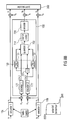
- Fig. 17 illustrates the same scenario as Fig. 16 , however, the details on the destination or NodeB are provided.
- LLRs are determined at the destination 1470 for the three receive signals y 1 , y 2 , and y R by the three detectors 1471, 1472, and 1473.
- Fig. 17 illustrates the concept of joint iterative decoding.
- the log likelihood ratio provided by the detector 1471 is, in a first step, provided to a first decoder 1475, in order to determine LLRs on the information word u 1 .
- the LLRs provided at the input of the decoder 1475 correspond to a-posteriori knowledge of the transmitted code words.
- a-priori knowledge on the information word u 1 is determined by evaluating the difference of the a-posteriori knowledge and the output of the decoder 1475.
- the a-priori knowledge is still available in terms of LLRs which can then be combined by the combiner 1476 with the LLRs determined by detector 1473 from the received signal y R on the combination determined at the relay station 1450.
- the combination can, for example, be determined by determining a combined LLR for an XOR-combination of the information words u 1 and u 2 . Subsequently, a derivation of the exact combination will be provided which is indicated by . From the a-priori knowledge on the first information word and the LLR on the combination, a-posteriori knowledge on the second information word can be determined, which is de-interleaved by de-interleaver 1477. The de-interleaver 1477 corresponds to the interleaver 1456 at the relay station 1450.
- the de-interleaved LLR at the output of the de-interleaver 1477 can then be combined with the LLRs detected by detector 1472 from the second receive signal y 2 , and provided as an input to the second decoder 1478.
- the second decoder 1478 then provides LLRs on the second information word u 2 at its output, from which the a-posteriori knowledge from the detector 1472 and the interleaver 1477 can be deducted for determining a-priori information, which may also be called extrinsic information.
- the interleaved LLRs can again be combined with the output of the detector 1473 by combiner 1480.
- A-posteriori information on the first information word u 1 is available at the output of the combiner 1480, which can again be combined with the a-posteriori knowledge at the output of the detector 1471.
- the above description corresponds to a first iteration loop of the joint iterative decoder, which is similar to the principle of turbo decoding. Multiple iteration loops may be carried out along the lines of the above description in order to determine more reliable information on the information words u 1 and u 2 .
- Fig. 18 illustrates the case, where at a relay station 1450 bad or weak radio channels are experienced and accordingly, LLRs are determined, which are equal or close to zero. Consequently, at the destination 1470, the LLRs determined by the detector 1473 equal zero, i.e. only very unreliable information is available. Consequently, the combinations carried out by combiners 1476 and 1480 also yield LLRs, which are zero. Therefore, within.the decoder, the LLRs of detector 1473 do not influence the LLRs determined by the detectors 1471 and 1472. In other words, if decoding at the relay station 1450 is very unreliable, decoding at the destination is solely based on the outputs of the detectors 1471 and 1472. The iterative process does not provide any benefits in this case.
- bit error rate Bit Error Rate
- two sources 1901 and 1902 transmit signals to a relay station 1903 and a destination 1904.
- SNR Signal-to-Noise Ratio
- SNR sr Signal-to-Noise Ratio
- a view chart depicts BER vs. SNR on the links between the sources 1901 and 1902 and the destination 1904.
- the links are symmetric, i.e. similar SNRs occur on the links of both sources 1901 and 1902 to the relay station 1903.
- SNR sr 5dB and results are shown for different SNR rd between the relay station 1903 and the destination 1904. The results illustrate that significant benefits can be obtained in BER if the signal quality on the link between the relay station 1903 and the destination 1904 increases.
- Fig. 20 illustrates similar simulation results. However, for the results in Fig. 20 , it was assumed that the SNR on the links between the sources 1901 and 1903, and the relay station 1903 was 0dB, i.e. more errors occur at the relay station 1903 than for the case considered in Fig. 19 . It can still, however, be observed that gains in BER can be obtained with increasing signal quality on the link between the relay station 1903 and the destination 1904.
- Fig. 21 shows a similar scenario using analog transmission from the relay station 1450 as explained with the assistance of Fig. 16 .
- the combined LLR L ( u R ) is illustrated. It can be seen from the view chart at the bottom of Fig. 21 that the combined LLR is approximately Gaussian distributed. Since analog transmission is used, large transmit powers need to be utilized, in order to transmit the combined LLR reliably, considering that they are superimposed by AWGN as well.
- Fig. 22 illustrates an option for at least partly overcoming the problem of having to utilize large transmission powers.
- the combined LLRs are processed by signal processor 1458, in which the hyperbolic tangent of the combined LLR is determined and used for analog transmission, also referred to as soft bit transmission in the following.
- a similar option is illustrated in Fig. 23 in which a quantizer 1459 is used for quantizing the LLRs at the relay station 1450, 1903 respectively.
- Fig. 23 shows at the top on the right-hand side the scenario as it was discussed above, involving the two sources 1901 and 1902, the relay station 1903, and the destination 1904. For the simulation results depicted on the left-hand side of Fig.
- the probability density of the LLR L R is shown assuming two quantizer regions separated by the dotted line.
- the two squares represent the quantizer values to be transmitted to the destination 1904. Having only two quantizer regions corresponds to transmitting only one bit per quantized value from the relay station 1903 to the destination 1904.
- almost no degradation due to the quantization occurs with respect to the trans- or mutual information, i.e. almost no information is lost due to quatization.
- Fig. 24 shows simulation results on the BER vs. the SNR sd on the link between the sources 1901 or 1902 and the destination 1904. For the simulations, it was assumed that the SNR sr between the sources 1901 and 1902 and the relay station 1903, is 3dB, for the SNR rd between the relay station 1903 and the destination 1904 0dB was assumed.
- the view chart on the left-hand side of Fig. 24 shows BER simulation results for analog transmission indicated by the square markers, soft bit analog transmission indicated by the triangular markers, and quantizer transmission using two quantizer regions, i.e. only one bit per quantizer value by the circular markers.
- the view chart on the left-hand side of Fig. 25 shows the probability density of the LLRs at the input of the quantizer 1459, the quantizer regions are separated by the dotted lines, and the representative values are indicated by square markers.
- the view graph on the left-hand side of Fig. 26 shows simulation results for analog transmission indicated by square markers, for soft bit transmission indicated by triangular markers and quantized transmission by circular markers. The simulation results indicate that no degradation at all can be observed when quantization is used.
- Fig. 27 illustrates another soft relay and network coding concept wherein quantized transmission from the relay station 1450 to the destination 1470 is used.
- An equation is illustrated at the top of Fig. 27 , which details the combination of the LLRs by the combiner 1457.
- the output of the combiner 1457 corresponds to the LLR, which can be obtained by an XOR combination of the information words u 1 and u 2 , and which is indicated in the equation at the top of Fig. 27 by an arrow operator pointing to the left.
- Fig. 27 illustrates another soft relay and network coding concept wherein quantized transmission from the relay station 1450 to the destination 1470 is used.
- An equation is illustrated at the top of Fig. 27 , which details the combination of the LLRs by the combiner 1457.
- the output of the combiner 1457 corresponds to the LLR, which can be obtained by an XOR combination of the information words u 1 and u 2 , and which is indicated in the equation at the top of Fig. 27 by
- FIG. 27 illustrates, within the relay station 1450, the quantizer 1459 for quantizing the combined LLRs to Z , the source coder 1460 for source coding the quantized combined LLRs and an encoder 1461 for channel encoding the source coded combined LLRs before transmission to the destination 1470.
- Fig. 28 illustrates a similar scenario, but shows that if one of the links between the encoders 1410;1420 and the relay station 1450 degrades, which is exemplified as the link between encoder 1410 and the relay station 1450 in Fig. 28 , the combined LLR becomes zero. Therefore, the SNR on the first hop, on the link between the sources and the relay station can be taken into account in the design of the quantizer.
- Fig. 29 shows another relay station 1450 in which the LLRs are jointly quantized by quantizer 1459 in order to take the signal quality into account, for which Fig. 30 illustrates the details of the quantizer.
- a quantizer for symmetric links is shown for which the mutual information after decoding equals 1.98bits.
- the relevant mutual information or trans-information after quantization equals 1.93bits, and since only two quantizer regions are utilized, only 1-bit is required for encoding the source encoded bits on the link between the relay station 1450 and the base station, or destination 1470.
- the quantizer regions are illustrated in the diagram at the top of Fig. 30 on the left hand side.
- a quantizer for asymmetric links is shown, for which the mutual information after decoding equals 1.16bits.
- the relevant mutual information after quantization equals 1.08bits, and since five quantizer regions are utilized, an average of 2.1bits per source coded bit is required.
- relaying is a promising method in order to overcome coverage limitations at reasonable cost.
- straightforward relaying methods lead to a capacity penalty factor of 0.5, since a time slot has to be split into two hops.
- Another problem is the processing delay in the relay, which may lead to a non-tolerable increase in the round-trip delay, which dues to the decoding at the relay station according to the above described concepts.
- the alternative of an amplify-and-forward relaying method which circumvents the decoding delay at the relay station, causes a lower processing delay, however, these schemes suffer from noise amplification in the relay.
- the object is achieved by a relay station according to claim 1, a method for relaying according to claim 9, a decoder according to claim 10, a method for decoding according to claim 15, and a system according to claim 17.
- Embodiments of the present invention are based on the finding that performance improvements can be achieved with respect to delay as well as with respect to error propagation, if the quantization rule at a relay station can be adapted to the signal quality of the received signals at the relay station, e.g. based on whether the signals at the relay station have been received correctly or not.
- the relay can use a quantizer from a set of available quantizers to compress its soft information, depending on the particular realizations of the channel fading on its incoming links, as for example, generally on an error detection mechanism for each incoming link to efficiently use the resources of the relay-destination link.
- the relay station After soft decoding of a received signal, the relay station has soft information available about its received signal. This soft information can be quantized by an optimized quantizer and forwarded to the destination, where the quantization can be based on a quantization rule, which in turn, is based on an error or signal quality detection mechanism.
- Embodiments of the present invention are further based on the finding that optionally, signals of multiple users can be quantized jointly, or a combination of them can be quantized at the relay station.
- the destination i.e. at the decoder
- joint decoding for all users, which have been processed jointly at the relay station can be performed using an iterative algorithm.
- Embodiments can achieve the advantage that noise enhancement is prevented at the relay station, since explicitly computed soft information is forwarded by the relay, rather than an amplified version of the noisy received signal.
- embodiments may achieve improved transmission characteristics as the relay station may use one quantizer from a set of available quantizers to compress its soft information, depending on the error detection or quality determination scheme at the relay station, and in further embodiments, even on the particular signal qualities of the signals received. Embodiments may therefore enable an efficient use of the resources between the relay station and the destination by taking knowledge about the quality of the received signals into account.
- Embodiments may achieve higher user satisfaction through higher throughputs and lower delays. Embodiments may provide coverage extensions with low cost relay stations and improved performance compared to conventional amplify-and-forward or decode-and-forward relay stations. Embodiments of systems carrying out said relaying concepts may provide diversity gain by using said relay stations and may realize low delay and high throughput, since the signals of multiple users can be processed, i.e. quantized, in combination or jointly with high efficiency at a relay station.
- Embodiments may comprise a decoder, which can for example, be implemented at a destination, a base station, a NodeB, etc., for decoding the quantized information from a relay station, and therewith realizing the above-described benefits.
- a decoder which can for example, be implemented at a destination, a base station, a NodeB, etc., for decoding the quantized information from a relay station, and therewith realizing the above-described benefits.
- each channel realization of a radio channel can be viewed as an additive white Gaussian noise (AWGN) channel with some instantaneous signal-to-noise ratio (SNR).
- AWGN additive white Gaussian noise
- SNR signal-to-noise ratio
- the relay station can then select a suitable quantizer for the particular realization of the fading coefficients on the source-relay links based on error or signal quality detection and/or the values of SNR sr,1 and SNR sr,2 .
- Each of the quantizers available at the relay may be designed with the information bottleneck method for the general (asymmetric) setting described in G. Zeitler, R. Koetter, G. Bauch, and J.Widmer, "On quantizer design for soft values in the multiple-access relay channel," submitted to the 2009 International Conference on Communications. Details of the quantizer design will be provided subsequently.
- the performance of the relaying scheme using quantized transmission in a block fading environment can be evaluated.
- the channel code specified in the UMTS will be used as described by European Telecommunications Standards Institute, "Universal mobile telecommunications system (UMTS): Multiplexing and channel coding (FDD),” 3GPP TS 125.212 version 3.4.0, Tech. Rep., 2000, standard for protection of the individual links in the network.
- UMTS Universal mobile telecommunications system
- FDD Multiplexing and channel coding
- Fig. 1a shows a general system model in which a first channel encoder 10a encodes an information word u 1 to a transmission symbol x 1 , which is transmitted to a first channel 12a to a relay station 100. Moreover, the same transmission symbol x 1 is transmitted through a second radio channel 14a to the destination 300. The received signal at the destination 300 is termed y d,1 . Furthermore, Fig. 1a shows a second channel encoder 10b encoding an information word u 2 to a second transmission symbol x 2 which is transmitted through a second radio channel 12b to the relay station 100.
- the signals received at the relay station are termed y r,1 for the signal received from the first channel encoder 10a and y r,2 for the signal received from the second channel encoder.
- the destination 300 receives a signal y d,2 from the second channel encoder 10b through the channel 14b.
- the relay station 100 transmits a signal x r through channel 14c through which the received signal y r is received by the destination 300.
- the distances between the sources and the relay, between the sources and the destination, and between the relay and the destination are given by d sr,i , d sd , i , and d rd , and the path-loss exponent is given by p.
- the fading coefficients a sr,i , a sd,i , and a rd are mutually independent and Rayleigh distributed with E [
- 2 ] E [
- 2 ] E [
- 2 ] 1.
- 2 ⁇ sr,i , ⁇ sd,i
- 2 ⁇ sd , i and ⁇ rd
- Fig. 1b shows an embodiment of a relay station 100 for being operative in a mobile communication system.
- GSM Global System for Mobile Communication
- UMTS Universal Mobile Telecommunication System
- LTE Long Term Evolution
- LTE-A Long Term Evolution Advanced
- WLAN Wireless Local Area Network
- the relay station 100 depicted in Fig. 1b comprises a receiver 110 for receiving a radio signal from a source, the radio signal comprising symbols representing encoded information, the encoded information being based on an encoding rule and comprising payload information and redundancy information.
- a symbol or transmit word may correspond to x 1 or x 2 .
- the relay station 100 further comprises a decoder 120 for determining soft information on the payload information and the redundancy information based on a symbol and a decoding rule associated with the encoding rule, the soft information comprising an information on a symbol and reliability information on the information on the symbol.
- the relay station 100 comprises a signal quality detector 130 for detecting a signal quality measure based on the soft information to obtain a signal quality indication.
- the relay station 100 further comprises a quantization rule selector 140 for selecting a quantization rule from a plurality of quantization rules based on the signal quality indication and a quantizer 150 for quantizing the soft information of the payload information based on the selected quantization rule to obtain quantized soft information. Furthermore, the relay station 100 comprises a transmitter 160 for transmitting the quantized soft information to a destination.
- the relay station 100 may comprise a signal quality detector 130 which is further adapted for determining an error based on the soft information on the redundancy information to obtain an error indication and the quantization rule selector 140 can be adapted for selecting a quantization rule further based on the error indication.
- CRC Cyclic Redundancy Check
- the relay station 100 may have a receiver 110 for receiving a radio signal y r,1 through the radio channel 12a from the source or channel encoder 10a.
- the quantization rule selector 140 can then be adapted for taking into account the signal quality measure when selecting the quantization rule.
- Embodiments of the quantization rule selector 140 may base the selection of the quantization rule on one of or a combination of the group of an outcome of a CRC, a BER, an FER, a SNR, a SINR, a SIR, a transmission capacity, etc.
- the receiver 110 can be adapted for receiving another radio signal from another source, the other radio signal comprising other symbols representing other encoded information, the other encoded information being based on another encoding rule and comprising other payload information and other redundancy information.
- the relay station 100 may comprise a receiver 110 which is adapted for receiving another radio signal y r,2 from the encoder 10b, i.e. comprising another symbol.
- the decoder 120 can be adapted for determining other soft information on the other payload information and the other redundancy information based on another symbol and another decoding rule the other decoding rule being associated with the other encoding rule, the other soft information comprising information on the other symbol, and reliability information on the information on the other symbol.
- the signal quality detector 130 can be adapted for determining another signal quality measure based on the other soft information to obtain another signal quality indication and correspondingly the quantization rule selector 140 can be adapted for selecting the quantization rule further based on the other signal quality indication.
- the quantizer 150 can be adapted for quantizing a combination of the soft information on the payload information and the other soft information on the other payload information to obtain the quantized soft information and/or for jointly quantizing the soft information on the payload information and the other soft information on the other payload information to obtain the quantized soft information.
- the signal quality detector 130 can be further adapted for determining another error based on the other soft information on the other redundancy information to obtain another error indication and the quantization rule selector 140 can be adapted for selecting the quantization rule further based on the other error indication.
- channel coding at the sources i.e. at the source and the other source
- channel codes at the sources are rate 1/2 turbo codes, as specified in the UMTS Standard with information block length k 1 and k 2 , respectively.
- the relay station performs soft decoding using its received words y r,1 and y r,2 .
- the output of a turbo decoder does not consist of true LLRs but rather of the beliefs of the belief propagation decoder
- the outputs of the soft decoders at the relay are still referred to as L 1 and L 2 .
- the turbo decoder can be seen as a device generating beliefs about the corresponding codeword, and since some situations are focused on where the relay cannot decode error-free, it is of particular interest whether the beliefs produced by the turbo decoder carry sufficient amount of mutual or trans-information about the code bits if reliable decoding is not possible. It was shown in P. E.
- Another effect observed is connected with the behavior of the mutual information between the decoder output and the codeword versus the number of iterations: in some cases, mutual information decreases again if the number of iterations is increased above a certain value. That effect, however, is fairly small, and therefore, although some of the stopping criteria found in the literature can be shown to halt the iterative process close to the maximal value of mutual information, a fairly small number of iterations at the relay are simply performed.
- Fig. 2 shows an embodiment of a decoder 300 for decoding a first encoded codeword to obtain a first soft information on a first codeword and for decoding a second encoded codeword to obtain second soft information on the second codeword.
- the decoder 300 comprises a first soft decoder 310 for determining the first soft information on the first codeword based on the first encoded codeword, and a second soft decoder 320 for determining second soft information on the second codeword based on the second encoded codeword and on second a-priori information.
- the decoder 300 comprises a first soft information renderer 330 for providing the second a-priori information based on the first soft information and quantized soft information, the quantized soft information being based on a combination of the first codeword and the second codeword. Furthermore, the decoder 300 comprises a second soft information renderer 340 for providing first a-priori information based on the second a-priori information, the quantized soft information and the second soft information.
- the first soft decoder 310 is adapted for determining updated first soft information on the first codeword based on the first encoded codeword and the first a-priori information.
- the first soft information renderer 330 can be adapted for providing updated second a-priori information based on the updated first soft information, the first a-priori information and the quantized soft information.
- the first soft decoder 310 can be adapted for determining the first soft information in terms of an LLR
- the second soft decoder 320 can be adapted for determining the second soft information in terms of an LLR
- the first soft information renderer 330 can be adapted for providing the second a-priori information in terms of an LLR
- the second soft information renderer 340 can be adapted for providing the first a-priori information in terms of an LLR.
- the decoder 300 may further comprise a receiver for receiving encoded quantized soft information and a decoder for decoding the encoded quantized soft information and a requantizer for providing the quantized soft information based on a quantization rule and the decoded encoded quantized soft information, wherein the receiver can be adapted for also receiving an information on the quantization rule.
- the receiver can be adapted for being operative in a mobile communication system, for example, a cellular system similar to the above-mentioned mobile communication systems.
- Fig. 3 illustrates a more detailed embodiment of an iterative decoder 300.
- Fig. 3 shows the first soft decoder 310 for determining first soft information at its output on the first codeword based on the first encoded codeword y 1 .
- the first soft decoder 310 is also adapted for determining first soft information or updated first soft information on the first codeword based on the encoded first codeword y 1 , and first a-priori information L A 1 .
- Fig. 3 shows the second soft decoder 320 for determining second soft information at its output on the second codeword based on the second encoded codeword y 2 and on second a-priori information L A 2 .
- Fig. 3 shows a first soft information renderer 330 for providing the second a-priori information L A 2 based on the first soft information provided by the first soft decoder 310 and quantized soft information y r received from a relay station 100.
- the first soft information renderer 330 first determines first extrinsic information L E 1 , for example, as a difference between the first soft information provided at the output of the first soft decoder 310 and the first a-priori information L A 1 .
- all soft information is considered in terms of LLRs.
- Fig. 3 shows a first soft information renderer 330 for providing the second a-priori information L A 2 based on the first soft information provided by the first soft decoder 310 and quantized soft information y r received from a relay station 100.
- the first soft information renderer 330 first determines first extrinsic information L E 1 , for example, as a difference between the first soft information provided at the output of the first soft decoder 310 and the
- the first soft information renderer 330 has a relay check node 335 in which interleaved second a-priori information is determined, based on a combination of the extrinsic information L E 1 and the quantized soft information. Moreover, the first soft information renderer 330 operates a de-interleaver 338 which de-interleaves L ⁇ ⁇ A 2 to obtain the second a-priori information L A 2 .
- Fig. 3 shows the second soft information renderer 340 providing first a-priori information L A 1 .
- the second soft information renderer 340 first determines second extrinsic information L E 2 based on a difference between the second soft information and the second a-priori information.
- the second soft information renderer 340 utilizes an interleaver 348 to interleave the second extrinsic information, and utilizes the relay check node 345 in order to combine the interleaved second extrinsic information L ⁇ ⁇ E 2 and the quantized soft information y r to obtain the first a-priori information L A 1 .
- each soft decoder is a turbo decoder. Iterative decoding in this case consists of inner iterations of the turbo decoder, and outer iterations over the relay check nodes. Like at the relay, it was found that performing a rather small number (4-6) of inner iterations gave good results in terms of extrinsic information.
- each of the soft decoders 310;320 may be implemented as a turbo decoder.
- the iterative decoder consists of four components in total, the EXIT curves for the two decoders 310;320 and the two relay check nodes 332;342 are the same due to the symmetry in the setup. Therefore, to obtain the EXIT chart for the entire decoder, it suffices to plot two curves only, one for the component decoder 310;320 and one for the relay check node 332;342.
- the goal is then to find a way of forwarding that information to the destination such that the EXIT curve in the decoder has maximal slope, subject to a constraint on the rate on the relay-destination link.
- the distortion measure has to be chosen and fixed in advance, and finding the right distortion measure for a particular problem is not an easy task in general.
- the function of the relay node should be: given an LLR L, transmit a quantized version Z that contains as much relevant information, which is information about X . That is, instead of forcing, e. g., the squared error between L and Z to be below some threshold, the goal is to preserve as much information as possible in Z about X .
- Tishby et al. take the following approach towards quantization of a random variable L .
- the goal is to min p z
- X ⁇ L ⁇ Z form a Markov chain, clearly I ( X ; Z ) ⁇ I ( X ; L ) due to the data processing inequality. That is, all that one can possibly aim for is preserving all the information available at the relay node about X in the quantizer output Z . Therefore, D ⁇ has to satisfy 0 ⁇ D ⁇ ⁇ I ( X ; L ).
- IBM Information Bottleneck Method
- the IBM can be used to compute a quantizer or quantization rule which, for a given source-relay SNR, maximizes the relevant information I ( X ; Z ), subject to a constraint on the rate on the relay destination link.
- the parameter ⁇ in the optimization algorithm has to be greatly larger than one to yield a deterministic mapping p ( z
- the rate of the quantizer chosen at the relay is such that the quantizer output Z can be communicated reliably to the destination.
- the quantizer design on L r will be referred to as the XOR-solution to the compression problem at the relay.
- the quantizer should be adapted to operate on L 1 and L 2 ⁇ directly, and accordingly, the quantizer design algorithm as well.
- the relay check node in the receiver processes Z and L E i to produce a-priori information for the corresponding component decoder.
- L E j I X i ; Z
- L E j . Due to the characteristic property of the relay check node of being almost a straight line, the problem simplifies to maximizing the output information for perfect input information I in 1.
- I rel I ( X 1 ; Z
- I rel I ( X 1 ; Z
- Fig. 5 provides a pseudo-code of algorithm 2, which may be carried out at the quantizer 150.
- the quantizer design in an embodiment may follow the above-described framwork using the general formulation of the information bottleneck method. Now, however, the distribution p ( z
- the point-to-point link not using the relay is taken as a reference for this system.
- the relay station is to be placed much closer to the destination than to the sources.
- the symmetry assumed here is only with respect to the distances and hence in terms of average SNR, but not in terms of instantaneous SNR.
- Fig. 6 illustrates two scenarios which are considered for the following simulations and which establish different fading cases.
- Fig. 6 illustrates the first case on the left-hand side in which two sources 61 and 62 transmit signals to the base station 63 and the destination 64, where in the first case the relay station 63 is located closer to the sources 61 and 62 than the destination 64.
- case 2 is depicted which differs from case 1 in that the relay station 63 is farther away from the sources 61 and 62 than the destination 64.
- the relay is placed behind the base station, resulting in an even worse source-relay link.
- d sr (3/2)
- This set of quantizers can be computed offline for various values of ⁇ sr ,1 and ⁇ sr ,2 . Assuming an error detection mechanism at the relay, the quantizers can be classified into three categories. First both users are decoded incorrectly at the relay, second only one user is decoded incorrectly at the relay, and third both users are decoded error-free.
- the relay station 100 may comprise a transmitter 160 which is adapted for transmitting an information on the selected quantization rule to the destination.
- the destination determines the quantizer used by the relay station 100 which in such embodiments is carried out by signaling the choice of the quantization rule or the quantizer to the destination or decoder 300, for example, by using 9 bits.
- the signaling is perfect, i.e. the decoder 300 or destination is completely informed about the quantizer or quantization rule selected by the relay station 100.
- Fig. 7 illustrates another embodiment for the general case.
- Fig. 7 shows an embodiment of the relay station 100, in which, for the sake of simplicity, the receiver 110 is not shown.
- Fig. 7 shows a decoder 120 for determining the soft information L 1 and L 2 based on the received symbols or words y r , 1 and y r ,2 .
- the decoder 120 shown in Fig. 7 is implemented as two separate soft decoders 121 and 122, which is one configuration among multiple configurations in embodiments of the decoder 120.
- Fig. 7 shows an interleaver 701 and a quantizer core 702.
- the section 700 comprises the signal quality detector 130, the quantization rule selector 140, and the quantizer 150, of which the details are not shown in Fig. 7 .
- the quantized soft information Z is available, which is then provided to a source encoder 710.
- the source encoder 710 is comprised in the transmitter 160.
- the transmitter 160 may further comprise a source coder 710 for source coding the quantized soft information Z .
- the transmitter 160 may comprise a channel encoder 720, for channel coding the source coder quantized soft information before transmitting according to Fig. 7 .
- the channel coder 720 may be adapted to operating at adaptive coding rates.
- the channel coder 720 can be configured to adapt the coding rate to a transmission capacity of a radio link to the destination.
- the source coding is necessary at this point since the quantizer output symbols are not equally likely in general.
- the source encoder output bits are channel encoded using the UMTS turbo code of appropriate rate and before being modulated using 16-QAM yielding the relay codeword x r of length 4000. Note that the rate of the turbo code at the relay must be adaptive since the rate of the quantizer depends on the values of the instantaneous SNR.
- Fig. 8a illustrates an embodiment of a relay check node 335 or 345 as explained in the above embodiments of the first soft information renderer 330 or the second soft information renderer 340, respectively.
- the relay check node 335 or 345 depicted in Fig. 8a provides the first a-priori information L A 1 , or an interleaved version of the second a-priori information L ⁇ ⁇ A 2 based on the first extrinsic information L E 1 or an interleaved version of the second extrinsic information L ⁇ ⁇ E 2 and the received quantized soft information y r .
- a channel decoder 805 may be comprised in the relay check node 335 or 345, in order to channel decode the encoded quantized soft information y r to obtain decoded quantized soft information û r . As indicated in Fig.
- a CRC check may also be carried out.
- a source decoded version of the quantized soft information ⁇ may be obtained by the source decoder 810 which can be comprised in embodiments of the relay check node 335 or 345, respectively.
- An LLR processor 815 may then be utilized to process the estimate of the quantized soft information ⁇ and the extrinsic information to obtain the a-priori information.
- an error detection mechanism e.g. CRC
- generally signal quality detection SNR, SINR, BER, FER, etc.
- the error and/or signal quality detection is used to select the appropriate quantizer, and the destination uses the error or signal quality detection mechanism to decide whether to make use of the signal received from the relay, since, if errors are detected in û r (cf. Fig. 8a ), the entire received signal block of the relay is discarded to avoid error propagation through the source decoder.
- Fig. 8b illustrates another embodiment of a relay station 100, embedded in a scenario as it has been discussed with respect to Fig. 1a .
- Fig. 8b depicts the details of the relay station 100 in which the error detector 130 is implemented as two separate error detectors 131 and 132 carrying out CRC checks on the first and second soft information output by the two decoders 121 and 122.
- the quantizer core 702 is assumed to comprise the quantization rule selector 140 and the quantizer 150.
- the two encoders 10a and 10b utilize turbo codes.
- the embodiment of the relay station 100 of Fig. 8b shall illustrate that the quantizer, i.e. the quantization rule may depend on the SNRs on the source relay links, i.e. on the signal quality between encoders 10a and 10b, and the relay station, as well as on the SNR between the relay station and the destination 300.
- the error detector 130 and the CRC checks 131 and 132 illustrate that embodiments may select the quantization rules dependent on whether the transmission between a source 10a, 10b, and the relay station 100 was error free, or erroneous.
- Fig. 8c shall illustrate the difference between the two cases of error free or erroneous decoding of the source to relay station signals in more detail.
- Fig. 8c illustrates the embodiment as depicted in Fig. 8b at the top, as well as two distributions of the soft information in terms of LLRs at the output of a decoder, on the left-hand side the error free decoding case is depicted, while on the right-hand side the case with the decoding errors is depicted.
- UMTS turbo codes at a rate of 1/2 at an SNR of -2dB was assumed.
- the probability, that values around 0 occur is vanishing, which indicates the error free decoding case.
- On the right-hand side it can be seen that there is a probability that soft information of 0 value will occur, for which error free decoding is not possible.
- Fig. 9 illustrates simulation results of the BER vs. the average source to destination SNR in dB for case 1, in which point-to-point transmission, a relay station to destination AWGN channel of 10dB, and a relay station-to-destination Rayleigh fading channel have been considered.
- Fig. 11 illustrates BERs vs. average source to destination SNR in dB for the second case, in which the same channel types have been considered, and consequently, Fig. 12a illustrates the corresponding frame error rates for the second case.
- case 1 where the relay is placed between the sources and the destination.
- the BER is plotted and frame-error-rate (FER) of the reference point-to-point link and the system using the relay with the three types of relay-destination links in Figs. 9 and 10 .
- FER frame-error-rate
- the best performance is achieved if the relay-destination link does not experience fading, and it can be seen that in this case, diversity is achieved.
- the relay-destination link is Rayleigh block fading, although at a slightly inferior performance than in a case where the relay-destination link is AWGN.
- Embodiments may realize an adaptive relay station that quantizes the soft information obtained after decoding. Embodiments may therewith avoid noise amplification as being introduced by amplify-and-forward methods and embodiments may further avoid error propagation as introduced by decode-and-forward schemes. Embodiments may provide the advantages of increased reliability in fading environments and adaptive processing at the relay station, which is made dependent on realizations of the fading channels on the source relay links, the signal quality measures, respectively.
- Embodiments may achieve advantages by introducing moderate signaling requirements for the quantizer choice between the relay station and the destination.
- FEC Forward Error Correction
- LDPC Low Density Parity Check Codes
- Embodiments may overcome the problem of error propagation by forwarding soft information after decoding to the destination as it occurs for high performance codes in the form of turbo codes or LDPC codes.
- Fig. 12b illustrates one section of the decoding graph, wherein on the left-hand side decoder 1 refers to the first soft decoder 310, and the decoder 2 on the right-hand side refers to the second soft decoder 320.
- the nodes labeled x 1, m and x 2, m are two variable nodes of the two different component channel codes coupled by the quantization at the relay.
- the direct observations from the two sources are the function nodes p ( y d ,1, m
- the destination exploits its knowledge of the quantizer chosen by the relay to obtain p ( x 1 , x 2
- z ) is the message passing equivalent of the LLR block 815 in Fig. 8a .
- the message passing rules are applied for function nodes to p ( x 1 , x 2
- Equation (5) is closely related to the boxplus computation in the symmetric case. Note that if L x 1 , m , x ⁇ 2 , m
- z m and - L ⁇ x 1 , m , x ⁇ 2 , m - 1
- m L A , m 1 L ⁇ E , m 2
- z m + e - L ⁇ x 1 , m - 1 , x ⁇ 2 , m
- Embodiments of the present invention may utilize the quantizer design framework which was introduced above for the received LLRs at the relay in symmetric AWGN channels using, for example, the IBM. Furthermore, embodiments may extend this method to the general case, i.e. lifting the symmetry requirement on the source-relay channels. Embodiments may, therefore, provide the advantage that efficient processing may be carried out at the relay station for several users jointly. Moreover, low delay may be achieved since no decoding has to be performed at the relay and noise amplification can be avoided.
- the inventive methods may be implemented in hardware or in software.
- the implementation can be formed using a digital storage medium, in particular a disc, a DVD or a CD, having an electronically readable control signal stored thereon which cooperates with the programmable computer, such that the inventive methods are performed.
- the present invention is therefore a computer program product with a program code for a machine-readable carrier, the program code being operative for performing the inventive methods when the computer program runs on a computer.
- the inventive methods are therefore a computer program having a program code for performing at least one of the inventive methods when the computer program runs on a computer.
Abstract
Description
- The present invention is in the field of wireless communication in a mobile communication system using relay stations.
- Conventional relaying concepts comprise, for example, standard relaying methods as amplify-and-forward relaying, decode-and-forward relaying, respectively. While amplify-and-forward relaying has low delay on the expense of noise amplification, decode-and-forward relaying causes a processing delay at the relay station, due to decoding. Moreover, decoding errors at the relay station may have detrimental effects on decoding at the destination.
- The designated purpose of a relay station in wireless networks is to facilitate the transmission of other users within the same cell, where one important benefit is provision of cooperative diversity as shown by A. Sendonaris, E. Erkip, and B. Aazhang, "Increasing uplink capacity via user cooperation diversity," in Proc. IEEE Int. Symp. on Information Theory, 1998. While the concept of network coding as shown by R. Ahlswede, N. Cai, S. R. Li, and R. W. Yeung, "Network information flow," IEEE Trans. Inf. Theory, vol. 46, no. 4, pp. 1204-1216, Apr. 2000 was originally developed to increase throughput in wireline networks, the application of network coding to wireless networks has been shown to effectively combat the effects of the fading channels shown by X. Bao and J. Li, "Matching code-on-graph with network-on-graph: Adaptive network coding for wireless relay networks," in Proc. 43rd Ann. Allerton Conf. on Communications, Control, and Computing, 2005, C. Hausl, F. Schreckenbach, I. Oikonomidis, G. Bauch, "Iterative network and channel decoding on a tanner graph," in Proc. 43rd Ann. Allerton Conf. on Communications, Control, and Computing, 2005 and Y. Chen, S. Kishore, and J. Li, "Wireless diversity through network coding," in Proc. IEEE Wireless Communications and Networking Conf., 2006 and L. Xiao, T. E. Fuja, J. Kliewer, and D. J. Costello, Jr., "Nested codes with multiple interpretations," in Proc. 40th Ann. Conf. on Information Sciences and Systems, 2006, thereby providing cooperative diversity.
- A common assumption is that the relay node or relay station can recover the source messages perfectly, thus restricting the investigation to relaying protocols based on the decode-and-forward (DF) as shown by the strategy of T. M. Cover and A. A. El Gamal, "Capacity theorems for the relay channel," IEEE Trans. Inf. Theory, vol. IT-25, no. 5, pp. 572-584, Sep. 1979, G. Kramer, M. Gastpar, and P. Gupta, "Cooperative strategies and capacity theorems for relay networks," IEEE Trans. Inf. Theory, vol. 51, no. 9, pp. 3037-3063, Sep. 2005, and L. Sankaranarayanan, G. Kramer, and N. B. Mandayam, "Hierarchical sensor networks: Capacity bounds and cooperative strategies using the multiple-access relay network," in IEEE Conf. on Sensor Networks, 2004, or to the strategy that the relay does not transmit at all if residual errors remain after decoding, provided there exists an error detection scheme at the relay node.
-
Fig. 13 illustrates a scenario and a radio network which utilizes multi-hop relaying.Fig. 13 shows a source s1 transmitting a symbol or a transmit word x 1, which is received by a relay station r and a destination d.Fig. 13 shows a second source s2 transmitting a second symbol or a transmit word x 2, which is also received by the relay station r and a destination d. Moreover, the relay station r transmits a symbol xr , which is also received by the destination. - Throughout, the multiple-access relay channel (MARC = Multiple Access Relay Channel) shown in
Fig. 13 with two sources s1, s2, one relay r and the destination d will be considered. The network geometry is assumed to be such that the relay is closer to the destination than to the sources, so that the source-relay channel quality is too low to permit reliable decoding at the relay. The relay-destination link, however, can support a higher rate due to its proximity to the destination. For such a scenario, the relay can make use of ideas from network coding as described by R. Ahlswede, N. Cai, S. R. Li, and R. W. Yeung, "Network information flow," IEEE Trans. Inf. Theory, vol. 46, no. 4, pp. 1204-1216, Apr. 2000 to form the log-likelihood ratios (LLRs) of the network coded message x 1 ⊕ x 2 and transmit these LLRs in an analog manner to the destination to significantly increase the receiver performance, as shown in S. Yang and R. Koetter, "Network coding over a noisy relay: a belief propagation approach," in Proc. IEEE Int. Symp. on Information Theory, 2007. - Other approaches with respect to relaying can be found in A. D. Wyner and J. Ziv, "The rate-distortion function for source coding with side information at the decoder," IEEE Trans. Inf. Theory, vol. IT-22, no. 1, pp. 1-10, Jan. 1976, A. Chakrabarti, A. de Baynast, A. Sabharwal, and B. Aazhang, "Half-duplex estimate-and-forward relaying: Bounds and code design," in Proc. IEEE Int. Symp. on Information Theory, 2006, pp. 1239-1243, N. Tishby, F. C. Pereira, and W. Bialek, "The information bottleneck method," in Proc. 37th Ann. Allerton Conf. on Communications, Control, and Computing, 1999, and G. Zeitler, R. Koetter, G. Bauch, and J. Widmer, "Design of network coding functions in multihop relay networks," in Proc. 5th symposium Turbo Codes and Related Topics, 2008.
- In E. Ayanoglu, et. al. "Diversity Coding of Transparent Self-Healing and Fault Tolerant Communication Networks", IEEE Transactions on Communications, Vol. 41, No. 11, November 1993, the authors disclose the concept of network coding, which is illustrated in
Fig. 14. Fig. 14 shows afirst encoder 1410 coding an information word u 1 to a first symbol or transmit word x 1, which is transmitted to arelay station 1450 and adestination 1470. Furthermore,Fig. 14 shows asecond encoder 1420, which encodes a second information word u 2 to a second symbol or transmit word x 2, which is also transmitted to therelay station 1450 and thedestination 1470. As indicated inFig. 14 at therelay station 1450, two symbols are received, superimposed by additive white Gaussian noise nr (AWGN = Additive White Gaussian Noise). Two decoders are operative at therelay station 1450, which are labeled "decoder 1" 1451 and "decoder 2" 1452 inFig. 14 . - Ideally, the two
decoders addition 1453 inFig. 14 and the combination is encoded by theencoder 1454 shown inFig. 14 . The encoded combined symbol xR is then transmitted from therelay station 1450 to thedestination 1470, where it is superimposed by AWGN nB . Three symbols or receive words are received at thedestination 1470, namely y 1 from "encoder 1" 1410, y 2 from "encoder 2" 1420, and yR from therelay station 1450. At thedestination 1470 joint decoding may be utilized in order to decode the information words u 1 and u 2. One disadvantage of the concept illustrated inFig. 14 is the delay, which is associated with decoding the received signal at therelay station 1450 in order to derive the information words and with encoding the combination of said information words again at therelay station 1450. - Another conventional approach is illustrated in
Fig. 15. Fig. 15 shows similar components as have been described with respect toFig. 14 , however, at therelay station 1450, instead of combining the decoded information words u 1 and u 2, ajoint encoder 1455 is utilized. Thejoint encoder 1455 may have the advantage that an increased block length can be used, which may particularly be beneficial for iterative decoding. Thejoint encoder 1455 may enable increased diversity which may be exploited at the joint decoder at thedestination 1470. However, high delays are still involved with decoding the received signals at the relay station and jointly encoding the decoded signals again, especially when increased block lengths are used. Another problem arises from decoding errors at therelay station 1450, which are re-encoded, and therewith extended or forwarded to thedestination 1470. - Yet another conventional approach is illustrated in
Fig. 16 , which shows similar components as have already been introduced with respect toFigs. 14 and15 .Fig. 16 illustrates the approach of analog transmission from therelay station 1450 to thedestination 1470, which may, for example, be implemented at a base station or a NodeB. The main difference with respect to the above explained concepts is that thedecoders relay station 1450 provide soft information in terms of log likelihood ratios (LLR = Log Likelihood Ratio) of the information words u 1 and u 2. An equation is shown at the top ofFig. 16 , which provides insight into a LLR of a general information word u. In a general case, the information word u may comprise only a single bit, which can take two values, namely +1 or -1. The so-called soft information can be determined by considering the quotient of the probability that the bit equals +1 and the probability that the bit equals -1, which is shown in the equation at the top ofFig. 16 . - Taking the logarithm of the quotient linearizes the soft information and maps the quotient from the range of positive real number to the full range of the real numbers. Consequently, taking the sign of the LLR corresponds to a hard decision detector. The magnitude of the LLR corresponds to reliability information.
- At the
relay station 1450 inFig. 16 , thedecoders Fig. 16 shows that therelay station 1450, the LLRs at the output of thesecond decoder 1452 are provided to aninterleaver 1456, which interleaves the LLRs. The interleaved LLRs from the second decoder are then combined by thecombiner 1457 before analog transmission is used to transmit information on the combination to thedestination 1470. Reliability information, in terms of the LLRs is therewith provided to the joint decoder at thedestination 1470. However, long delays still occur at therelay station 1450 in order to determine the soft information by the twodecoders -
Fig. 17 illustrates the same scenario asFig. 16 , however, the details on the destination or NodeB are provided. As can be seen fromFig. 17 , LLRs are determined at thedestination 1470 for the three receive signals y 1, y 2, and yR by the threedetectors Fig. 17 illustrates the concept of joint iterative decoding. The log likelihood ratio provided by thedetector 1471 is, in a first step, provided to afirst decoder 1475, in order to determine LLRs on the information word u 1. The LLRs provided at the input of thedecoder 1475 correspond to a-posteriori knowledge of the transmitted code words. At the output of thedecoder 1475, a-priori knowledge on the information word u 1 is determined by evaluating the difference of the a-posteriori knowledge and the output of thedecoder 1475. The a-priori knowledge is still available in terms of LLRs which can then be combined by thecombiner 1476 with the LLRs determined bydetector 1473 from the received signal yR on the combination determined at therelay station 1450. - The combination can, for example, be determined by determining a combined LLR for an XOR-combination of the information words u 1 and u 2. Subsequently, a derivation of the exact combination will be provided which is indicated by. From the a-priori knowledge on the first information word and the LLR on the combination, a-posteriori knowledge on the second information word can be determined, which is de-interleaved by de-interleaver 1477. The de-interleaver 1477 corresponds to the

interleaver 1456 at therelay station 1450. The de-interleaved LLR at the output of the de-interleaver 1477 can then be combined with the LLRs detected bydetector 1472 from the second receive signal y 2, and provided as an input to thesecond decoder 1478. Thesecond decoder 1478 then provides LLRs on the second information word u 2 at its output, from which the a-posteriori knowledge from thedetector 1472 and theinterleaver 1477 can be deducted for determining a-priori information, which may also be called extrinsic information. - After interleaving 1479, the interleaved LLRs can again be combined with the output of the
detector 1473 bycombiner 1480. A-posteriori information on the first information word u 1 is available at the output of thecombiner 1480, which can again be combined with the a-posteriori knowledge at the output of thedetector 1471. The above description corresponds to a first iteration loop of the joint iterative decoder, which is similar to the principle of turbo decoding. Multiple iteration loops may be carried out along the lines of the above description in order to determine more reliable information on the information words u 1 and u 2. -
Fig. 18 illustrates the case, where at arelay station 1450 bad or weak radio channels are experienced and accordingly, LLRs are determined, which are equal or close to zero. Consequently, at thedestination 1470, the LLRs determined by thedetector 1473 equal zero, i.e. only very unreliable information is available. Consequently, the combinations carried out bycombiners detector 1473 do not influence the LLRs determined by thedetectors relay station 1450 is very unreliable, decoding at the destination is solely based on the outputs of thedetectors -
Fig. 19 illustrates simulation results on the bit error rate (BER = Bit Error Rate) for the scenario, which is depicted on the left-hand side ofFig. 19 . In this scenario twosources relay station 1903 and adestination 1904. Moreover, on all links signal-to-noise ratios (SNR = Signal-to-Noise Ratio) are given, namely, SNRsr on the links between thesources relay station 1903, SNRsd on the links between thesources destination 1904, and SNRrd for the link between therelay station 1903 and thedestination 1904. On the right-hand side of theFig. 19 , a view chart depicts BER vs. SNR on the links between thesources destination 1904. For the simulations, it was assumed that the links are symmetric, i.e. similar SNRs occur on the links of bothsources relay station 1903. Moreover, for the results depicted on the right-hand side ofFig. 19 , it was assumed that SNRsr=5dB and results are shown for different SNRrd between therelay station 1903 and thedestination 1904. The results illustrate that significant benefits can be obtained in BER if the signal quality on the link between therelay station 1903 and thedestination 1904 increases. -
Fig. 20 illustrates similar simulation results. However, for the results inFig. 20 , it was assumed that the SNR on the links between thesources relay station 1903 was 0dB, i.e. more errors occur at therelay station 1903 than for the case considered inFig. 19 . It can still, however, be observed that gains in BER can be obtained with increasing signal quality on the link between therelay station 1903 and thedestination 1904. -
Fig. 21 shows a similar scenario using analog transmission from therelay station 1450 as explained with the assistance ofFig. 16 . At the bottom ofFig. 21 the combined LLR L(uR ) is illustrated. It can be seen from the view chart at the bottom ofFig. 21 that the combined LLR is approximately Gaussian distributed. Since analog transmission is used, large transmit powers need to be utilized, in order to transmit the combined LLR reliably, considering that they are superimposed by AWGN as well. -
Fig. 22 illustrates an option for at least partly overcoming the problem of having to utilize large transmission powers. At therelay station 1450, the combined LLRs are processed bysignal processor 1458, in which the hyperbolic tangent of the combined LLR is determined and used for analog transmission, also referred to as soft bit transmission in the following. A similar option is illustrated inFig. 23 in which aquantizer 1459 is used for quantizing the LLRs at therelay station Fig. 23 shows at the top on the right-hand side the scenario as it was discussed above, involving the twosources relay station 1903, and thedestination 1904. For the simulation results depicted on the left-hand side ofFig. 23 , it was assumed that the SNRsr of the links between thesources relay station 1903 is 3dB. At the bottom right-hand side ofFig. 23 , the details of therelay station quantizer 1459 is shown. - In the view chart on the left-hand side the probability density of the LLR LR is shown assuming two quantizer regions separated by the dotted line. The two squares represent the quantizer values to be transmitted to the
destination 1904. Having only two quantizer regions corresponds to transmitting only one bit per quantized value from therelay station 1903 to thedestination 1904. In this scenario it can be observed that almost no degradation due to the quantization occurs with respect to the trans- or mutual information, i.e. almost no information is lost due to quatization. -
Fig. 24 shows simulation results on the BER vs. the SNRsd on the link between thesources destination 1904. For the simulations, it was assumed that the SNRsr between thesources relay station 1903, is 3dB, for the SNRrd between therelay station 1903 and thedestination 1904 0dB was assumed. The view chart on the left-hand side ofFig. 24 shows BER simulation results for analog transmission indicated by the square markers, soft bit analog transmission indicated by the triangular markers, and quantizer transmission using two quantizer regions, i.e. only one bit per quantizer value by the circular markers. It can be observed that the degradation, when using the quantized values, occurs only for high SNRs between the sources and the destination, whereas for rather low SNRs between the sources and the destination, transmitting the quantized value provides improvements in the BER, which is due to the AWGN taking higher effect on the analog transmission for low SNRs. -
Fig. 25 illustrates another simulation scenario, in which five quantizer regions were assumed for a scenario, in which the SNRsr=0dB, i.e. it is lower than in the above discussed scenario. Since five quantizer regions were assumed, an average of 2.3bits have to be transmitted per quantized value after source coding. The view chart on the left-hand side ofFig. 25 shows the probability density of the LLRs at the input of thequantizer 1459, the quantizer regions are separated by the dotted lines, and the representative values are indicated by square markers. -
Fig. 26 shows simulation results on the BER when SNRsr=3dB is assumed for the links between thesources relay station 1903, and an SNR of 0.44dB is assumed for the link between therelay station 1903 and thedestination 1904. The view graph on the left-hand side ofFig. 26 shows simulation results for analog transmission indicated by square markers, for soft bit transmission indicated by triangular markers and quantized transmission by circular markers. The simulation results indicate that no degradation at all can be observed when quantization is used. -
Fig. 27 illustrates another soft relay and network coding concept wherein quantized transmission from therelay station 1450 to thedestination 1470 is used. An equation is illustrated at the top ofFig. 27 , which details the combination of the LLRs by thecombiner 1457. The output of thecombiner 1457 corresponds to the LLR, which can be obtained by an XOR combination of the information words u 1 and u 2, and which is indicated in the equation at the top ofFig. 27 by an arrow operator pointing to the left. Moreover,Fig. 27 illustrates, within therelay station 1450, thequantizer 1459 for quantizing the combined LLRs to Z, thesource coder 1460 for source coding the quantized combined LLRs and anencoder 1461 for channel encoding the source coded combined LLRs before transmission to thedestination 1470. - In the example depicted in
Fig. 27 , it is the task of thequantizer 1459 to compress Lr as much as possible while preserving the relevant information about uR = u 1 ⊕ u 2 in the quantized signal Z. This is expressed by the equation at the bottom ofFig. 27 which indicates that the distribution of the quantizer region Z for a given LLR should be chosen, so as to minimize the difference between trans-information I(Lr ,Z) between the LLR Lr and the chosen quantizer Z, and the trans-information I(Ur ,Z) between the combined information words Ur and the chosen quantizer Z, which is expressed in the equation in terms of a Lagrangian problem based on factor β. -
Fig. 28 illustrates a similar scenario, but shows that if one of the links between theencoders 1410;1420 and therelay station 1450 degrades, which is exemplified as the link betweenencoder 1410 and therelay station 1450 inFig. 28 , the combined LLR becomes zero. Therefore, the SNR on the first hop, on the link between the sources and the relay station can be taken into account in the design of the quantizer. -
Fig. 29 shows anotherrelay station 1450 in which the LLRs are jointly quantized byquantizer 1459 in order to take the signal quality into account, for whichFig. 30 illustrates the details of the quantizer. On the left-hand side ofFig. 30 , a quantizer for symmetric links is shown for which the mutual information after decoding equals 1.98bits. The relevant mutual information or trans-information after quantization equals 1.93bits, and since only two quantizer regions are utilized, only 1-bit is required for encoding the source encoded bits on the link between therelay station 1450 and the base station, ordestination 1470. The quantizer regions are illustrated in the diagram at the top ofFig. 30 on the left hand side. - On the right-hand of
Fig. 30 , a quantizer for asymmetric links is shown, for which the mutual information after decoding equals 1.16bits. The relevant mutual information after quantization equals 1.08bits, and since five quantizer regions are utilized, an average of 2.1bits per source coded bit is required. - Summarizing the conventional concepts, relaying is a promising method in order to overcome coverage limitations at reasonable cost. However, straightforward relaying methods lead to a capacity penalty factor of 0.5, since a time slot has to be split into two hops. Another problem is the processing delay in the relay, which may lead to a non-tolerable increase in the round-trip delay, which dues to the decoding at the relay station according to the above described concepts. The alternative of an amplify-and-forward relaying method, which circumvents the decoding delay at the relay station, causes a lower processing delay, however, these schemes suffer from noise amplification in the relay.
- It is the object of the present invention to provide an improved concept for relaying.
- The object is achieved by a relay station according to
claim 1, a method for relaying according to claim 9, a decoder according toclaim 10, a method for decoding according toclaim 15, and a system according to claim 17. - Embodiments of the present invention are based on the finding that performance improvements can be achieved with respect to delay as well as with respect to error propagation, if the quantization rule at a relay station can be adapted to the signal quality of the received signals at the relay station, e.g. based on whether the signals at the relay station have been received correctly or not. One of the findings is that the relay can use a quantizer from a set of available quantizers to compress its soft information, depending on the particular realizations of the channel fading on its incoming links, as for example, generally on an error detection mechanism for each incoming link to efficiently use the resources of the relay-destination link.
- After soft decoding of a received signal, the relay station has soft information available about its received signal. This soft information can be quantized by an optimized quantizer and forwarded to the destination, where the quantization can be based on a quantization rule, which in turn, is based on an error or signal quality detection mechanism.
- Embodiments of the present invention are further based on the finding that optionally, signals of multiple users can be quantized jointly, or a combination of them can be quantized at the relay station. At the destination, i.e. at the decoder, joint decoding for all users, which have been processed jointly at the relay station can be performed using an iterative algorithm. Embodiments can achieve the advantage that noise enhancement is prevented at the relay station, since explicitly computed soft information is forwarded by the relay, rather than an amplified version of the noisy received signal.
- Moreover, embodiments may achieve improved transmission characteristics as the relay station may use one quantizer from a set of available quantizers to compress its soft information, depending on the error detection or quality determination scheme at the relay station, and in further embodiments, even on the particular signal qualities of the signals received. Embodiments may therefore enable an efficient use of the resources between the relay station and the destination by taking knowledge about the quality of the received signals into account.
- Embodiments may achieve higher user satisfaction through higher throughputs and lower delays. Embodiments may provide coverage extensions with low cost relay stations and improved performance compared to conventional amplify-and-forward or decode-and-forward relay stations. Embodiments of systems carrying out said relaying concepts may provide diversity gain by using said relay stations and may realize low delay and high throughput, since the signals of multiple users can be processed, i.e. quantized, in combination or jointly with high efficiency at a relay station.
- Embodiments may comprise a decoder, which can for example, be implemented at a destination, a base station, a NodeB, etc., for decoding the quantized information from a relay station, and therewith realizing the above-described benefits.
- Embodiments of the present invention will be detailed using the accompanying figures, in which:
-
Fig. 1a shows a general overview of a system model; -
Fig. 1b illustrates an embodiment of a relay station; -
Fig. 2 illustrates an embodiment of a decoder; -
Fig. 3 illustrates another embodiment of a decoder; -
Fig. 4a illustrates an EXIT curve for a relay check node; -
Fig. 4b provides a pseudocode on a first optimization algorithm; -
Fig. 5 provides a pseudocode on a second optimization algorithm; -
Fig. 6 illustrates two simulation scenarios; -
Fig. 7 illustrates operations of an embodiment in the general case; -
Fig. 8a illustrates operations of a relay check node in an embodiment; -
Fig. 8b illustrates another embodiment of a relay station; -
Fig. 8c illustrates two soft information distributions within one embodiment; -
Fig. 9 illustrates simulation results; -
Fig. 10 illustrates simulation results; -
Fig. 11 illustrates simulation results; -
Fig. 12a illustrates simulation results; -
Fig. 12b illustrates one section of a decoding graph of an embodiment; -
Fig. 12c illustrates one section of a decoding graph of an embodiment with messages; -
Fig. 13 illustrates a general transmission scenario; -
Fig. 14 illustrates a state of the art relaying concept; -
Fig. 15 illustrates another state of the art relaying concept; -
Fig. 16 illustrates another state of the art relaying concept; -
Fig. 17 illustrates a state of the art joint iterative decoder; -
Fig. 18 illustrates a joint iterative decoder in a scenario in which the source to relay channel is weak; -
Fig. 19 illustrates simulation results of state of the art concepts; -
Fig. 20 illustrates simulation results of state of the art concepts; -
Fig. 21 illustrates another state of the art relaying concept; -
Fig. 22 illustrates another state of the art relaying concept; -
Fig. 23 illustrates a state of the art relaying concept with quantization; -
Fig. 24 illustrates simulation results of a state of the art concept; -
Fig. 25 illustrates another state of the art relaying concept with quantization; -
Fig. 26 shows simulation results of state of the art concepts; -
Fig. 27 shows another state of the art relaying concept; -
Fig. 28 illustrates another state of the art relaying concept for a weak source to relay station channel; -
Fig. 29 illustrates another state of the art relaying concept utilizing a quantizer; and -
Fig. 30 illustrates quantizer dimensioning for a state of the art relaying concept. - In the following, embodiments of the present invention will be detailed based on the accompanying figures. In the figures, similar components or components having similar tasks will have similar reference signs. Generally, the following considerations will be carried out with respect to a scenario as it has already been explained and illustrated in
Fig. 13 . In the following, the expressions "relay", "relay station" and "relay apparatus" are used synonymously. - Due to the block fading nature, each channel realization of a radio channel can be viewed as an additive white Gaussian noise (AWGN) channel with some instantaneous signal-to-noise ratio (SNR). In embodiments the relay station can then select a suitable quantizer for the particular realization of the fading coefficients on the source-relay links based on error or signal quality detection and/or the values of SNRsr,1 and SNRsr,2. Each of the quantizers available at the relay may be designed with the information bottleneck method for the general (asymmetric) setting described in G. Zeitler, R. Koetter, G. Bauch, and J.Widmer, "On quantizer design for soft values in the multiple-access relay channel," submitted to the 2009 International Conference on Communications. Details of the quantizer design will be provided subsequently.
- Generally in embodiments, for a given quantizer design framework for asymmetric source-relay channels, the performance of the relaying scheme using quantized transmission in a block fading environment can be evaluated. Further, to allow for easy integration of embodiments of relay stations in already existing mobile communication networks, the channel code specified in the UMTS will be used as described by European Telecommunications Standards Institute, "Universal mobile telecommunications system (UMTS): Multiplexing and channel coding (FDD)," 3GPP TS 125.212 version 3.4.0, Tech. Rep., 2000, standard for protection of the individual links in the network.
-
Fig. 1a shows a general system model in which afirst channel encoder 10a encodes an information word u1 to a transmission symbol x1, which is transmitted to afirst channel 12a to arelay station 100. Moreover, the same transmission symbol x1 is transmitted through asecond radio channel 14a to thedestination 300. The received signal at thedestination 300 is termed yd,1. Furthermore,Fig. 1a shows asecond channel encoder 10b encoding an information word u2 to a second transmission symbol x2 which is transmitted through asecond radio channel 12b to therelay station 100. The signals received at the relay station are termed yr,1 for the signal received from thefirst channel encoder 10a and yr,2 for the signal received from the second channel encoder. Moreover, thedestination 300 receives a signal yd,2 from thesecond channel encoder 10b through thechannel 14b. Therelay station 100 transmits a signal xr throughchannel 14c through which the received signal yr is received by thedestination 300. - A network with three phases is considered, where the two sources and the relay broadcast their codewords over mutually orthogonal channels. Generally embodiments are not limited to such scenarios. The system model in
Fig. 1a includes the block fading channels, so that the received signals at the relay and at the destination read as


where the noise variables follow a circular symmetric complex normal distribution with variances σ2, respectively. The distances between the sources and the relay, between the sources and the destination, and between the relay and the destination are given by d sr,i,d sd,i , and drd , and the path-loss exponent is given by p. The fading coefficients a sr,i,asd,i , and ard are mutually independent and Rayleigh distributed with E[|a sr,i |2]=E[|a sd,i |2]=E[|ard |2]=1. The average values of the SNR on the different links are then given by


and the instantaneous SNRs depending on the particular realization of the fading coefficients are γ sr,i =|a sr,i |2ρ sr,i , γ sd,i =|asd,i |2ρ sd,i and γ rd =|ard |2ρ rd . A common assumption is made that the transmitters only know the average values of the SNR for their corresponding channels, but not the realizations of the fading coefficients, and that the receivers know the instantaneous SNRs. In particular, the relay is assumed to have no knowledge, about neither the average, nor instantaneous SNRs, on the source-destination links. -
Fig. 1b shows an embodiment of arelay station 100 for being operative in a mobile communication system. In general, embodiments of therelay station 100 may be operative in all kinds of radio communication systems, as for example, GSM (GSM = Global System for Mobile Communication), UMTS (UMTS = Universal Mobile Telecommunication System), LTE (LTE = Long Term Evolution), LTE-A (LTE-A = Long Term Evolution Advanced), WLAN (WLAN = Wireless Local Area Network), etc. - The
relay station 100 depicted inFig. 1b comprises areceiver 110 for receiving a radio signal from a source, the radio signal comprising symbols representing encoded information, the encoded information being based on an encoding rule and comprising payload information and redundancy information. Referring back toFig. 1a , such a symbol or transmit word may correspond to x1 or x2. - The
relay station 100 further comprises adecoder 120 for determining soft information on the payload information and the redundancy information based on a symbol and a decoding rule associated with the encoding rule, the soft information comprising an information on a symbol and reliability information on the information on the symbol. Moreover, therelay station 100 comprises asignal quality detector 130 for detecting a signal quality measure based on the soft information to obtain a signal quality indication. - As shown in
Fig. 1b , therelay station 100 further comprises aquantization rule selector 140 for selecting a quantization rule from a plurality of quantization rules based on the signal quality indication and aquantizer 150 for quantizing the soft information of the payload information based on the selected quantization rule to obtain quantized soft information. Furthermore, therelay station 100 comprises atransmitter 160 for transmitting the quantized soft information to a destination. - In embodiments, the
relay station 100 may comprise asignal quality detector 130 which is further adapted for determining an error based on the soft information on the redundancy information to obtain an error indication and thequantization rule selector 140 can be adapted for selecting a quantization rule further based on the error indication. In embodiments thesignal quality detector 130 may be adapted to obtain the error indication based on a CRC (CRC = Cyclic Redundancy Check). In other words the signal quality measure may correspond to an error measure and the signal quality indication may correspond to the error indication. - In other words, referring back to
Fig. 1a , therelay station 100 may have areceiver 110 for receiving a radio signal yr,1 through theradio channel 12a from the source orchannel encoder 10a. Thesignal quality detector 130 may be adapted for determining the signal quality measure, which may for example correspond to a signal-to-noise ratio (SNR = Signal-to-Noise Ratio), a signal-to-noise-and-interference ratio (SINR = Signal-to-Noise-and-Interference Ratio), a signal-to-interference ratio (SIR = Signal-to-Interference Ratio), a transmission capacity, an outcome of a CRC, a bit-error rate (BER = Bit Error Rate), a frame error rate (FER = Frame Error Rate), etc., and thequantization rule selector 140 can then be adapted for taking into account the signal quality measure when selecting the quantization rule. Embodiments of thequantization rule selector 140 may base the selection of the quantization rule on one of or a combination of the group of an outcome of a CRC, a BER, an FER, a SNR, a SINR, a SIR, a transmission capacity, etc. - In embodiments, the
receiver 110 can be adapted for receiving another radio signal from another source, the other radio signal comprising other symbols representing other encoded information, the other encoded information being based on another encoding rule and comprising other payload information and other redundancy information. In other words, referring toFig. 1a , therelay station 100 may comprise areceiver 110 which is adapted for receiving another radio signal y r,2 from theencoder 10b, i.e. comprising another symbol. - In embodiments, the
decoder 120 can be adapted for determining other soft information on the other payload information and the other redundancy information based on another symbol and another decoding rule the other decoding rule being associated with the other encoding rule, the other soft information comprising information on the other symbol, and reliability information on the information on the other symbol. - Furthermore, in embodiments, the
signal quality detector 130 can be adapted for determining another signal quality measure based on the other soft information to obtain another signal quality indication and correspondingly thequantization rule selector 140 can be adapted for selecting the quantization rule further based on the other signal quality indication. Thequantizer 150 can be adapted for quantizing a combination of the soft information on the payload information and the other soft information on the other payload information to obtain the quantized soft information and/or for jointly quantizing the soft information on the payload information and the other soft information on the other payload information to obtain the quantized soft information. - In embodiments, the
signal quality detector 130 can be further adapted for determining another error based on the other soft information on the other redundancy information to obtain another error indication and thequantization rule selector 140 can be adapted for selecting the quantization rule further based on the other error indication. - In the following, channel coding at the sources, i.e. at the source and the other source, will be considered. For example, channel codes at the sources are
rate 1/2 turbo codes, as specified in the UMTS Standard with information block length k 1 and k 2, respectively. In the following simulation results will be presented, for which it was assumed k=k 1=k 2=2000. - In an embodiment, the relay station performs soft decoding using its received words y r,1 and y r,2. Although the output of a turbo decoder does not consist of true LLRs but rather of the beliefs of the belief propagation decoder, the outputs of the soft decoders at the relay are still referred to as L 1 and L 2. From a high level point of view, the turbo decoder can be seen as a device generating beliefs about the corresponding codeword, and since some situations are focused on where the relay cannot decode error-free, it is of particular interest whether the beliefs produced by the turbo decoder carry sufficient amount of mutual or trans-information about the code bits if reliable decoding is not possible. It was shown in P. E. Tawk, "Decoding of turbo codes for maximum extrinsic information at codes rates above capacity," Master's thesis, Technische Universität München, 2008 that this is the case, and moreover, that in those cases where the code rate is such that the decoder cannot decode error-free, a rather small number of iterations in the range of 4-6 iterations is sufficient.
- Another effect observed is connected with the behavior of the mutual information between the decoder output and the codeword versus the number of iterations: in some cases, mutual information decreases again if the number of iterations is increased above a certain value. That effect, however, is fairly small, and therefore, although some of the stopping criteria found in the literature can be shown to halt the iterative process close to the maximal value of mutual information, a fairly small number of iterations at the relay are simply performed.
-
Fig. 2 shows an embodiment of adecoder 300 for decoding a first encoded codeword to obtain a first soft information on a first codeword and for decoding a second encoded codeword to obtain second soft information on the second codeword. Thedecoder 300 comprises a firstsoft decoder 310 for determining the first soft information on the first codeword based on the first encoded codeword, and a secondsoft decoder 320 for determining second soft information on the second codeword based on the second encoded codeword and on second a-priori information. Furthermore, thedecoder 300 comprises a firstsoft information renderer 330 for providing the second a-priori information based on the first soft information and quantized soft information, the quantized soft information being based on a combination of the first codeword and the second codeword. Furthermore, thedecoder 300 comprises a secondsoft information renderer 340 for providing first a-priori information based on the second a-priori information, the quantized soft information and the second soft information. The firstsoft decoder 310 is adapted for determining updated first soft information on the first codeword based on the first encoded codeword and the first a-priori information. - In embodiments, the first
soft information renderer 330 can be adapted for providing updated second a-priori information based on the updated first soft information, the first a-priori information and the quantized soft information. - In embodiments, the first
soft decoder 310 can be adapted for determining the first soft information in terms of an LLR, the secondsoft decoder 320 can be adapted for determining the second soft information in terms of an LLR, the firstsoft information renderer 330 can be adapted for providing the second a-priori information in terms of an LLR, and the secondsoft information renderer 340 can be adapted for providing the first a-priori information in terms of an LLR. - In embodiments, the first
soft information renderer 330 can be adapted for determining the second a-prioriinformation 

wherein
soft information renderer 340 can be adapted for determining the first a-prioriinformation 

wherein
- In embodiments, the
decoder 300 may further comprise a receiver for receiving encoded quantized soft information and a decoder for decoding the encoded quantized soft information and a requantizer for providing the quantized soft information based on a quantization rule and the decoded encoded quantized soft information, wherein the receiver can be adapted for also receiving an information on the quantization rule. - In embodiments, the receiver can be adapted for being operative in a mobile communication system, for example, a cellular system similar to the above-mentioned mobile communication systems.
-
Fig. 3 illustrates a more detailed embodiment of aniterative decoder 300.Fig. 3 shows the firstsoft decoder 310 for determining first soft information at its output on the first codeword based on the first encoded codeword y 1. The firstsoft decoder 310 is also adapted for determining first soft information or updated first soft information on the first codeword based on the encoded first codeword y 1, and first a-prioriinformation 
Fig. 3 shows the secondsoft decoder 320 for determining second soft information at its output on the second codeword based on the second encoded codeword y 2 and on second a-prioriinformation 
- Moreover,
Fig. 3 shows a firstsoft information renderer 330 for providing the second a-prioriinformation 
soft decoder 310 and quantized soft information y r received from arelay station 100.Fig. 3 shows that the firstsoft information renderer 330 first determines first extrinsicinformation 
soft decoder 310 and the first a-prioriinformation 
Fig. 3 illustrates that the firstsoft information renderer 330 has arelay check node 335 in which interleaved second a-priori information is determined, based on a combination of the extrinsicinformation 
soft information renderer 330 operates a de-interleaver 338 which de-interleaves
information 
- Moreover,
Fig. 3 shows the secondsoft information renderer 340 providing first a-prioriinformation 
soft information renderer 340 first determines second extrinsicinformation 
soft information renderer 340 utilizes aninterleaver 348 to interleave the second extrinsic information, and utilizes therelay check node 345 in order to combine the interleaved second extrinsic information
information 
- At the destination, in an embodiment the
decoder structure 300 is as shown inFig. 3 , where now, each soft decoder is a turbo decoder. Iterative decoding in this case consists of inner iterations of the turbo decoder, and outer iterations over the relay check nodes. Like at the relay, it was found that performing a rather small number (4-6) of inner iterations gave good results in terms of extrinsic information. In other words, in embodiments each of thesoft decoders 310;320 may be implemented as a turbo decoder. - In the following, a quantizer design at the relay station will be explained. Due to the obvious resemblance of the
decoder 300 with a normal turbo decoder, analysis tools like the Extrinsic Information Transfer (EXIT = EXtrinsic Information Transfer) chart as shown by S. ten Brink, "Convergence behavior of iteratively decoded parallel concatenated codes," IEEE Trans. Comm., vol. 49, no. 10, pp. 1727-1737, Oct. 2001, prove to be useful also for this distributed turbo decoder. - Although the iterative decoder consists of four components in total, the EXIT curves for the two
decoders 310;320 and the two relay check nodes 332;342 are the same due to the symmetry in the setup. Therefore, to obtain the EXIT chart for the entire decoder, it suffices to plot two curves only, one for thecomponent decoder 310;320 and one for the relay check node 332;342. The EXIT curve of the relay node 332;342 describes how information at the output of one component decoder acting as input information

-
Fig. 4a illustrates an EXIT chart of a relay check node, which was determined for SNRsr,1=SNRsr,2=0.5dB, SNRrd=2.28dB, and for three quantization regions. It turns out that the EXIT curve of the relay check node 332;342 is almost a straight line never exceeding the diagonal of the EXIT chart, seeFig. 4a for an example. The higher the slope of the check node EXIT curve, the better the information from the relay node, with the curve approaching the diagonal for perfect reliability of the messages from the relay. Provided that the channel quality on the channels from the sources to the relay determines the amount of information available at the relay, the goal is then to find a way of forwarding that information to the destination such that the EXIT curve in the decoder has maximal slope, subject to a constraint on the rate on the relay-destination link. - If Lm ∈ l, this is equivalent to seeking a function


- In the following, a design of the relay station function of an embodiment will be provided. Rate distortion theory dictates that, given a sequence of i.i.d. random variables L 1,L 2,...,Ln from the source alphabet ℓ distributed according to p(ℓ), the minimum rate required to represent the source at distortion D by a random variable Z from the reproduction alphabet


where
- Instead of putting the constraint on the average distortion for some chosen distortion measure, the constraint is that the reproduction variable Z should contain some minimum level of information about a third variable, the relevant variable, which, in some embodiments, is the random variable X=X 1⊕X' 2. This is exactly what the function of the relay node should be: given an LLR L, transmit a quantized version Z that contains as much relevant information, which is information about X. That is, instead of forcing, e. g., the squared error between L and Z to be below some threshold, the goal is to preserve as much information as possible in Z about X.
- In the following, the information bottleneck method will be explained, which may in embodiments be used in order to determine the quantization rule. In the information bottleneck method, Tishby et al. take the following approach towards quantization of a random variable L. Given the joint distribution p(x,ℓ), the goal is to

where the constraint is now on preserving the relevant information I(X;Z). Since X↔L↔Z form a Markov chain, clearly I(X;Z)≤I(X;L) due to the data processing inequality. That is, all that one can possibly aim for is preserving all the information available at the relay node about X in the quantizer output Z. Therefore, D̃ has to satisfy 0≤D̃≤I(X;L). - Using that p(x,ℓ) is fixed and the Markov chain condition X↔L↔Z, one obtains that

- Since I(X;L) is fixed for a given p(x,ℓ), the minimization in (1) is equivalent to the standard rate distortion problem

where now, the right distortion measure d(ℓ,z) is the relative entropy between p(x|ℓ) and p(x|z), i.e.,
and D̃=I(X;L)-D̃. Note that by putting the constraint on I(X;Z) as in (1), one arrives at an equivalent formulation as a rate distortion problem, for which the evidently right distortion measure d(ℓ,z) emerged as the relative entropy D(p(x| - ℓ)∥p(x|z)).
- Introducing the Lagrangian M = I(L;Z)-βI(X;Z) for some β>0 and evaluating the Karush-Kuhn-Tucker (KKT) conditions, the optimal distribution p(z|ℓ) can be given an exact characterizing solution as described in N. Tishby, F. C. Pereira, and W. Bialek, "The information bottleneck method," in Proc. 37th Ann. Allerton Conf. on Communications, Control, and Computing, 1999, and is shown to be

where N(ℓ,β) is a normalizing term ensuring that p(z|ℓ) is a probability distribution fulfilling Σz p(z|ℓ)=1. However, it is to be noted that the solution specified by (2) is an implicit solution only, since the probability distribution p(z|ℓ) is the only free variable, and both p(z) and p(x|z) are fully determined by p(z|ℓ). - Although the optimal distribution p(z|ℓ) cannot be obtained in closed form, an iterative optimization algorithm used in embodiments can be shown to converge to a local optimum. In essence, this algorithm is very similar to the Blahut-Arimoto algorithm described by R. E. Blahut, "Computation of channel capacity and rate-distortion functions," IEEE Trans. Inf. Theory, vol. IT-18, no. 4, pp. 460-473, Jul. 1972 for computing channel capacities and rate distortion functions, with the main difference that the algorithm for computing the mapping in the information bottleneck setting updates p(x|z) as well.
Fig. 4b provides a pseudo code for a respective iterative optimization algorithm. - In the following, the application of the information bottleneck method (IBM = Information Bottleneck Method) to the relay network according to one embodiment will be discussed.
- The IBM can be used to compute a quantizer or quantization rule which, for a given source-relay SNR, maximizes the relevant information I(X;Z), subject to a constraint on the rate on the relay destination link. To accomplish this, the parameter β in the optimization algorithm has to be greatly larger than one to yield a deterministic mapping p(z|ℓ), and the distribution p(x,ℓ) is obtained for the particular value of SNRsr. Summarizing, by designing the quantizer at the relay with the IBM, one can maximize the slope of the EXIT curve of the relay check node, thereby optimizing the convergence properties of the iterative decoder. Throughout, it is assumed that the rate of the quantizer chosen at the relay is such that the quantizer output Z can be communicated reliably to the destination. In the following, the quantizer design on L r will be referred to as the XOR-solution to the compression problem at the relay.
- The above investigations can be seen as limited to the case where the source-relay links are symmetric with respect to the SNR. If however, the source-relay links are of different channel quality, then the reliability of L r about the network coded message will be dominated by the user with the weaker source-relay channel. Therefore, in order for the relay to be able to handle asymmetric source-relay links effectively, the quantizer should be adapted to operate on L 1 and

- In the following, a general embodiment will be considered and the quantizer design in the asymmetric case will be discussed. As in the symmetric case, the framework for the quantizer design will be provided by the IBM, but with a different expression as relevant information, whose choice will be motivated in the following. As mentioned above, the EXIT curve of the relay check node is almost a straight line with Iout =I(X;Z) for Iin =1, and for the symmetric case considered above, the curves are the same for both check nodes in the decoder. In general however, these curves will be different. During the iterative decoding process, the
component decoders 310;320 andsoft information renderers 330;340 produce randomvariables 


decoder 1 todecoder 2, and the information exchange fromdecoder 2 todecoder 1. Since
one is left with maximizing
- Now, perfect input information means that

decoder 1 todecoder 2, I(X 2;Z|X 1) should be maximized, and analogously, fordecoder 1 to receive maximal information fromdecoder 2, I(X 1;Z|X 2) should be as large as possible. - Various combinations of these information expressions can be taken to form the relevant information term for the IBM. For example, choosing Irel =min{I(X1 ;Z|X 2),I(X2 ;Z|X 1)} as the relevant information expression will aim for keeping the turbo loop in the iterative decoder running as long as possible. However, if one user has a very bad source-relay link, that choice of Irel also claims much of the rate of the relay-destination link for communicating very unreliable information about that users data. Therefore, it is proposed in some embodiments to take the average of I(X 1;Z|X 2) and I(X 2;Z|X 1) as the relevant information term, so that the relay can opportunistically allocate more of its rate to the user with the better source-relay channel. In terms of the IBM, to design a quantizer at the relay, one solves

where now, the relevant information is Irel =I(X 1;Z|X 2)+I(X 2;Z|X 1). Rewriting Irel as
allows another interpretation of the relevant information expression: choose the mapping p(z|ℓ1,ℓ2) such that Z contains as much information about the pair (X 1, X 2) while carrying little information about X 1 and X 2 alone. For some multiplier β>0, the implicit solution to this problem can be shown to be

where D(p∥q) is the relative entropy between p and q, and N(ℓ1,ℓ2,β) is a normalizing term ensuring that p(z|ℓ1,ℓ2) is a valid probability distribution. To compute a locally optimal solution to (3), one can use an adapted version of the information bottleneck algorithm, summarized inAlgorithm 2 inFig. 5 , restricting the embodiment to β>>0 to obtain a two-dimensional quantizer using the deterministic mapping p(z|ℓ1,ℓ2).Fig. 5 provides a pseudo-code ofalgorithm 2, which may be carried out at thequantizer 150. - The quantizer design in an embodiment may follow the above-described framwork using the general formulation of the information bottleneck method. Now, however, the distribution p(z|ℓ1,ℓ2) has to be obtained numerically for the UMTS turbo code of
rate 1/2, at various values of the SNR. - In the following, simulation results will be used to demonstrate the benefits of the above-described relaying concept involving the
relay station 100 and thedecoder 300 at the destination. - To assess the performance of the proposed relaying scheme with quantization at the relay in a block fading environment, the point-to-point link not using the relay is taken as a reference for this system. The information blocks u 1 and u 2 of length k 1 =k 2=2000 are encoded with the UMTS turbo code of
rate 1/3 and BPSK modulated yielding the signals x 1 and x 2 of length m 1 =m 2=6000. Since the relay is absent, communication is taking place in two phases on two orthogonal channels from the sources to the destination. - In the system with the relay, as shown in
Fig. 13 , the sources use the UMTS turbo code to encode and BPSK modulate their messages u 1 and u 2 of length k 1=k 2=2000 into the transmit signals x 1 and x 2 of length m 1=m 2=4000. In the third phase, the relay sends m 3=4000 symbols from its modulation alphabet M , which is chosen to be 16-QAM. - Throughout, it is assumed that the relay station is to be placed much closer to the destination than to the sources. Moreover, it is assumed that the network to be symmetric such that d sr,1=d sr,2=dsr and d sd,1=d sd,2=dsd . Note that the symmetry assumed here is only with respect to the distances and hence in terms of average SNR, but not in terms of instantaneous SNR. Hence, one has ρ sr,1=ρ sr,2=ρ sr and ρ sd,1=ρ sd,2=ρ sd .
-
Fig. 6 illustrates two scenarios which are considered for the following simulations and which establish different fading cases.Fig. 6 illustrates the first case on the left-hand side in which twosources base station 63 and thedestination 64, where in the first case therelay station 63 is located closer to thesources destination 64. On the right-hand side ofFig. 6 ,case 2 is depicted which differs fromcase 1 in that therelay station 63 is farther away from thesources destination 64. - For the simulations, it is considered having the two scenarios depicted in
Fig. 6 . In the first case, the relay is placed between the sources and the destination such that the source-relay distance is 9/10 of the source-destination distance, so that dsr =(9/10)dsd . With a path-loss exponent of ρ=3.52 and the above relation for the distances, ρ sr =ρ sd +35.2log10(10/9) is received. Due to the proximity of the relay to the destination, a fairly high SNR on the relay-destination link is assumed. Concretely, two possible locations for the relay are considered: the first one places the relay on the street level with no direct line-of-sight connection to the destination, making the relay-destination link Rayleigh block fading with average SNR of ρ rd =ρ sd +15dB. Alternatively, one can position the relay above the street level on the rooftop of a building, giving it a strong line-of-sight connection, which is modeled to be AWGN with average SNR ρ rd =10dB. - In the second scenario, the relay is placed behind the base station, resulting in an even worse source-relay link. dsr =(3/2)dsd is chosen so that ρ sr =ρ sd +35.2log10(2/3), again with a path-loss coefficient of p=3.52. As in
case 1, two scenarios for the placement of the relay were considered, above rooftop and below rooftop. Accordingly, the relay-destination link is either AWGN with ρ rd =10dB or Rayleigh block fading with ρ rd =ρ sd +15dB. Both the relay and the destination share a set of quantizers designed with the information bottleneck method. This set of quantizers can be computed offline for various values of γ sr,1 and γ sr,2. Assuming an error detection mechanism at the relay, the quantizers can be classified into three categories. First both users are decoded incorrectly at the relay, second only one user is decoded incorrectly at the relay, and third both users are decoded error-free. - Since the relay is assumed to be placed in the vicinity of the destination with a channel supporting a fairly high rate, it was opted for quantizers with N=4...6 quantization regions, thus making use of the available rate on the relay-destination link. In category 1 (residual errors in both users codewords), for every pair of instantaneous SNR values γ sr,1 and γ sr,2 in the set

one quantizer with N=5 regions is obtained. In category 2 (residual errors in one user's codeword), a quantizer with N = 6 is computed for every value of the γ sr,1 or γ sr,2 in S. - Finally, there is one more quantizer for
category 3 with N=4 regions. In total, since |S|=16 one therefore has
quantizers available corresponding to the plurality of quantization rules in the present embodiment, where the additional factors of 2 are necessary to take into account the order of the two users. - In embodiments, the
relay station 100 may comprise atransmitter 160 which is adapted for transmitting an information on the selected quantization rule to the destination. To perform decoding using the relay signal, the destination determines the quantizer used by therelay station 100 which in such embodiments is carried out by signaling the choice of the quantization rule or the quantizer to the destination ordecoder 300, for example, by using 9 bits. In the following, it will be assumed that the signaling is perfect, i.e. thedecoder 300 or destination is completely informed about the quantizer or quantization rule selected by therelay station 100. -
Fig. 7 illustrates another embodiment for the general case.Fig. 7 shows an embodiment of therelay station 100, in which, for the sake of simplicity, thereceiver 110 is not shown.Fig. 7 shows adecoder 120 for determining the soft information L 1 and L 2 based on the received symbols or words y r ,1 and y r,2. Thedecoder 120 shown inFig. 7 is implemented as two separatesoft decoders decoder 120. In asection 700,Fig. 7 shows aninterleaver 701 and aquantizer core 702. For simplicity reasons, thesection 700 comprises thesignal quality detector 130, thequantization rule selector 140, and thequantizer 150, of which the details are not shown inFig. 7 . At the outcome of thequantizer 150 orquantizer core 702 the quantized soft information Z is available, which is then provided to asource encoder 710. As depicted inFig. 7 , thesource encoder 710 is comprised in thetransmitter 160. In other words, in embodiments thetransmitter 160 may further comprise asource coder 710 for source coding the quantized soft information Z. Moreover, in embodiments thetransmitter 160 may comprise achannel encoder 720, for channel coding the source coder quantized soft information before transmitting according toFig. 7 . In embodiments, thechannel coder 720 may be adapted to operating at adaptive coding rates. Thechannel coder 720 can be configured to adapt the coding rate to a transmission capacity of a radio link to the destination. - As shown in
Fig. 7 , after soft decoding, the relay chooses the right quantizer or quantization rule, performs quantization yielding the quantizer output
- In embodiments, the
signal quality detector 130 may be adapted for detecting the error indication based on a cyclic redundancy check (CRC = Cyclic Redundancy Check). - At the
decoder 300 site, the two relay check nodes, as described with the assistance ofFig. 3 , may in turn consider the corresponding signal processing means at the decoder or destination site.Fig. 8a illustrates an embodiment of arelay check node soft information renderer 330 or the secondsoft information renderer 340, respectively. - As it has been explained for the above embodiments, the
relay check node Fig. 8a provides the first a-prioriinformation 

information 

relay station 100, achannel decoder 805 may be comprised in therelay check node Fig. 8a , a CRC check may also be carried out. From the channel decoded quantized soft information a source decoded version of the quantized soft information Ẑ may be obtained by thesource decoder 810 which can be comprised in embodiments of therelay check node LLR processor 815 may then be utilized to process the estimate of the quantized soft information Ẑ and the extrinsic information to obtain the a-priori information. - Throughout, an error detection mechanism (e.g. CRC) or generally signal quality detection (SNR, SINR, BER, FER, etc.) is assumed, both at the relay and at the destination, for the signal received from the relay. At the relay, the error and/or signal quality detection is used to select the appropriate quantizer, and the destination uses the error or signal quality detection mechanism to decide whether to make use of the signal received from the relay, since, if errors are detected in ûr (cf.
Fig. 8a ), the entire received signal block of the relay is discarded to avoid error propagation through the source decoder. -
Fig. 8b illustrates another embodiment of arelay station 100, embedded in a scenario as it has been discussed with respect toFig. 1a .Fig. 8b depicts the details of therelay station 100 in which theerror detector 130 is implemented as twoseparate error detectors decoders Fig. 8b , thequantizer core 702 is assumed to comprise thequantization rule selector 140 and thequantizer 150. Moreover, it is assumed that the twoencoders Fig. 8b the typical waterfall behavior for the bit error rate (BER = Bit Error Rate) vs. the SNR is depicted. The embodiment of therelay station 100 ofFig. 8b shall illustrate that the quantizer, i.e. the quantization rule may depend on the SNRs on the source relay links, i.e. on the signal quality betweenencoders destination 300. Theerror detector 130 and the CRC checks 131 and 132 illustrate that embodiments may select the quantization rules dependent on whether the transmission between asource relay station 100 was error free, or erroneous. -
Fig. 8c shall illustrate the difference between the two cases of error free or erroneous decoding of the source to relay station signals in more detail.Fig. 8c illustrates the embodiment as depicted inFig. 8b at the top, as well as two distributions of the soft information in terms of LLRs at the output of a decoder, on the left-hand side the error free decoding case is depicted, while on the right-hand side the case with the decoding errors is depicted. For both view graphs, UMTS turbo codes at a rate of 1/2 at an SNR of -2dB was assumed. On the left-hand side it can be seen that the probability, that values around 0 occur, is vanishing, which indicates the error free decoding case. On the right-hand side it can be seen that there is a probability that soft information of 0 value will occur, for which error free decoding is not possible. - In the following, numerical simulation results will be considered. Simulation results will be presented for the two cases illustrated in
Fig. 6 .Fig. 9 illustrates simulation results of the BER vs. the average source to destination SNR in dB forcase 1, in which point-to-point transmission, a relay station to destination AWGN channel of 10dB, and a relay station-to-destination Rayleigh fading channel have been considered.Fig. 10 shows frame error rates (FER = Frame Error Rate) vs. SNRs on the source to destination or base station links, for the first case, for which different channel types have been considered, namely transmission with no relay station, transmission with a relay station to base station AWGN with 10dB SNR, and transmission with a relay station-to-base station Rayleigh fading channel.Fig. 11 illustrates BERs vs. average source to destination SNR in dB for the second case, in which the same channel types have been considered, and consequently,Fig. 12a illustrates the corresponding frame error rates for the second case. - First,
case 1 is considered, where the relay is placed between the sources and the destination. The BER is plotted and frame-error-rate (FER) of the reference point-to-point link and the system using the relay with the three types of relay-destination links inFigs. 9 and10 . As expected, the best performance is achieved if the relay-destination link does not experience fading, and it can be seen that in this case, diversity is achieved. However, it can be seen that diversity can be gained even if the relay-destination link is Rayleigh block fading, although at a slightly inferior performance than in a case where the relay-destination link is AWGN. - Placing the relay behind the destination in
case 2, still allows a diversity gain in the system for both pure AWGN and Rayleigh fading on the relay-destination link, as shown inFigs. 11 and12a . Now, however, for low values of the average SNR on the source destination links, the point-to-point connection slightly outperforms the relay system. This is owed to the fact that despite the low average source-destination SNR and large distance from the sources to the relay, the relay is allowed to send m 3=m 2=m 1=4000 symbols, thereby allotting the same amount of time for transmissions from the relay as to the two sources, although on average, very little information is received at the relay. - This may be considered in embodiments for proper allocation of the timing parameters to optimize the system performance. Embodiments may realize an adaptive relay station that quantizes the soft information obtained after decoding. Embodiments may therewith avoid noise amplification as being introduced by amplify-and-forward methods and embodiments may further avoid error propagation as introduced by decode-and-forward schemes. Embodiments may provide the advantages of increased reliability in fading environments and adaptive processing at the relay station, which is made dependent on realizations of the fading channels on the source relay links, the signal quality measures, respectively.
- Embodiments may achieve advantages by introducing moderate signaling requirements for the quantizer choice between the relay station and the destination.
- Embodiments of the present invention may especially be used in systems with a capacity-approaching FEC (FEC = Forward Error Correction) codes, as for example turbo codes or LDPC (LDPC = Low Density Parity Check Codes). Embodiments may overcome the problem of error propagation by forwarding soft information after decoding to the destination as it occurs for high performance codes in the form of turbo codes or LDPC codes.
-
Fig. 12b illustrates one section of the decoding graph, wherein on the left-hand side decoder 1 refers to the firstsoft decoder 310, and thedecoder 2 on the right-hand side refers to the secondsoft decoder 320. - The nodes labeled x 1,m and x 2,m are two variable nodes of the two different component channel codes coupled by the quantization at the relay. The direct observations from the two sources are the function nodes p(y d,1,m |x1,m ) and p(y' d,2,m |x'2,m ), whereas the coupling through the quantization at the relay is expressed in the function node p(x 1,m ,x'2,m |zm ).
- Since Z is assumed to be available perfectly at the receiver, the destination exploits its knowledge of the quantizer chosen by the relay to obtain p(x 1,x 2|z), which is among the output of the iterative optimization algorithm. Note that the function node p(x 1,x2 |z) is the message passing equivalent of the
LLR block 815 inFig. 8a . To find processing rules for theLLRs 


one obtains that

- A detailed derivation of the above expressions will be provided in the following.
- Equation (5) is closely related to the boxplus computation in the symmetric case. Note that if

and
they simplify to

- It turns out that application of the general quantizer design algorithm to symmetric SR channels can result in a distribution p(x 1,x 2|z) such that

and
so that the XOR-solution is recovered in those situations without computing L r first. - In the following, a derivation of the message passing rules for the general case, as mentioned above, will be provided with the assistance of
Fig. 12c , one section of a decoding graph was chosen which includes the messages which will be introduced in the following. - Expressions on how LLRs are exchanged are derived by the component codes connected by the function node p(x 1,x 2|z). Some definitions are needed before proceeding. Let x 1,m be the m-th element of x 1, and let x'2,m be the m-th element of x'2, and assume that x 1,m and x'2,m are connected by p(x 1,m ,x' 2,m |zm ). Let µA(x 1,m ) and µE (x'2,m ) be the messages from and to the check node, respectively, as shown in
Fig. 12c . Further, define

Fig. 12c shows one section of the decoding graph with the corresponding messages. - The message passing rules for function nodes are applied in the following to compute


one obtains
- Using the definitions in Eq. (4), one obtains that

- Along the lines of the derivations above, one can also compute

where
and
- Embodiments of the present invention may utilize the quantizer design framework which was introduced above for the received LLRs at the relay in symmetric AWGN channels using, for example, the IBM. Furthermore, embodiments may extend this method to the general case, i.e. lifting the symmetry requirement on the source-relay channels. Embodiments may, therefore, provide the advantage that efficient processing may be carried out at the relay station for several users jointly. Moreover, low delay may be achieved since no decoding has to be performed at the relay and noise amplification can be avoided.
- Depending on certain implementation requirements of the inventive methods, the inventive methods may be implemented in hardware or in software. The implementation can be formed using a digital storage medium, in particular a disc, a DVD or a CD, having an electronically readable control signal stored thereon which cooperates with the programmable computer, such that the inventive methods are performed. Generally, the present invention is therefore a computer program product with a program code for a machine-readable carrier, the program code being operative for performing the inventive methods when the computer program runs on a computer. In other words, the inventive methods are therefore a computer program having a program code for performing at least one of the inventive methods when the computer program runs on a computer.
Claims (17)
- A relay station (100) for being operative in a mobile communication system, comprising
a receiver (110) for receiving a radio signal from a source, the radio signal comprising symbols representing encoded information, the encoded information being based on an encoding rule and comprising payload information and redundancy information;
a decoder (120) for determining soft information on the payload information and the redundancy information based on a symbol and a decoding rule associated with the encoding rule, the soft information comprising an information on the symbol and reliability information on the information on the symbol;
a signal quality detector (130) for detecting a signal quality measure based on the soft information to obtain a signal quality indication;
a quantization rule selector (140) for selecting a quantization rule from a plurality of quantization rules based on the signal quality indication;
a quantizer (150) for quantizing the soft information on the payload information based on the selected quantization rule to obtain quantized soft information; and
a transmitter (160) for transmitting the quantized soft information to a destination. - The relay station (100) of claim 1, wherein the signal quality detector (130) is further adapted for determining an
error based on the soft information on the redundancy information to obtain an error indication and wherein the quantization rule selector (140) is adapted for selecting the quantization rule further based on the error indication. - The relay station (100) of one of the claims 1 or 2, wherein the receiver (110) is adapted for receiving another radio signal from another source, the other radio signal comprising other symbols representing other encoded information, the other encoded information being based on another encoding rule and comprising other payload information and other redundancy information,
wherein the decoder (110) is adapted for determining other soft information on the other payload information and the other redundancy information based on another symbol and another decoding rule associated with the other encoding rule, the other soft information comprising an information on the other symbol and reliability information on the information on the other symbol,
wherein the signal quality detector (130) is adapted for detecting another signal quality measure based on the other soft information to obtain another signal quality indication,
wherein the quantization rule selector (140) is adapted for selecting the quantization rule further based on the other signal quality indication,
and the quantizer (150) is adapted for quantizing a combination of the soft information on the payload information and the other soft information on the other payload information to obtain the quantized soft information or for jointly quantizing the soft information on the payload
information and the other soft information on the other payload information. - The relay station (100) of the claim 3, wherein the signal quality detector (130) is further adapted for determining another error based on the other soft information on the other redundancy information to obtain another error indication, and wherein the quantization rule selector (140) is adapted for selecting the quantization rule further based on the other error indication.
- The relay station (100) of one of the claims 1 to 4, wherein the transmitter (160) is adapted for transmitting an information on the selected quantization rule.
- The relay station (100) of one of the claims 1 to 5, wherein the transmitter (160) further comprises a source coder for source coding the quantized soft information and a channel coder for channel coding the source coded quantized soft information before transmitting.
- The relay station (100) of claim 6, wherein the channel coder operates at an adaptive coding rate, the channel coder being configured to adapt the coding rate to a transmission capacity of a radio link to the destination.
- The relay station (100) of one of the claims 2 to 7, wherein the signal quality detector (130) is adapted for detecting the error indication or the other error indication based on a cyclic redundancy check.
- A method for relaying in a mobile communication system, comprising the steps of:receiving a radio signal from a source, the radio signal comprising symbols representing encoded information, the encoded information being based on an encoder rule and comprising payload information and redundancy information;determining soft information on the payload information and the redundancy information based on a symbol and a decoding rule associated with the encoding rule, the soft information comprising an information on the symbol and reliability information on the information on the symbol;determining a signal quality measure based on the soft information to obtain a signal quality indication;selecting a quantization rule from a plurality of quantization rules based on the signal quality indication;quantizing the soft information on the payload information based on the selected quantization rule to obtain quantized soft information; andtransmitting the quantized soft information to a destination.
- A decoder (300) for decoding a first encoded codeword to obtain first soft information on a first codeword and for decoding a second encoded codeword to obtain second soft information on a second codeword, comprising
a first soft decoder (310) for determining the first soft information on the first codeword based on the first encoded codeword;
a second soft decoder (320) for determining the second soft information on the second codeword based on the second encoded codeword and second α-priori information;
a first soft information renderer (330) for providing the second α-priori information based on the first soft information and quantized soft information, the quantized soft information being based on a combination of the first codeword and the second codeword; and
a second soft information renderer (340) for providing first α-priori information based on the second α-priori information, the quantized soft information and the second soft information;
wherein the first soft decoder (310) is adapted for determining updated first soft information on the first codeword based on the encoded first codeword and the first a-priori information. - The decoder (300) of claim 10, wherein the first soft information renderer (330) is adapted for providing updated second α-priori information based on the updated first soft information, the first α-priori information and the quantized soft information.
- The decoder (300) of one of the claims 10 or 11, wherein the first soft decoder (310) is adapted for determining the first soft information in terms of an LLR, wherein the second soft decoder (320) is adapted for determining the second soft information in terms of an LLR, wherein the first soft information renderer (330) is adapted for providing the second α-priori information in terms of an LLR, wherein the second soft information renderer (340) is adapted for providing the first α-priori information in terms of an LLR, and wherein the first soft information renderer (330) is adapted for determining the second α-priori information


wherein


wherein
- The decoder (300) of one of the claims 10 to 12, further comprising a receiver for receiving an encoded quantized soft information and a decoder for decoding the encoded quantized soft information and a re-quantizer for providing the quantized soft information based on a quantization rule and the decoded encoded quantized soft information, wherein the receiver is further adapted for receiving an information on the quantization rule.
- The decoder (300) of one of the claims 10 to 13, wherein the receiver is adapted for receiving in a cellular mobile communication system.
- A method for decoding a first encoded codeword to obtain first soft information on a first codeword and for decoding a second encoded codeword to obtain second soft information on a second codeword, comprising the steps of
determining the first soft information on the first codeword based on the first encoded codeword;
determining second soft information on the second codeword based on the second encoded codeword and second α-priori information;
providing the second α-priori information based on the first soft information and quantized soft information, the quantized soft information being based on a combination of the first codeword and the second codeword;
providing first α-priori information based on the second a-priori information, the quantized soft information and the second soft information; and
determining updated first soft information on the first codeword based on the encoded first codeword and the first a-priori information. - Computer program having a program code for performing one of the methods according to claim 9 or 15, when the program runs on a computer or processor.
- System comprising a relay station (100) according to one of the claims 1 to 8 and a decoder (300) according to one of the claims 10 to 14.
Priority Applications (2)
| Application Number | Priority Date | Filing Date | Title |
|---|---|---|---|
| EP20080022422 EP2202904B1 (en) | 2008-12-23 | 2008-12-23 | A relay station and a decoder |
| JP2009292357A JP4918586B2 (en) | 2008-12-23 | 2009-12-24 | Relay station and decoder |
Applications Claiming Priority (1)
| Application Number | Priority Date | Filing Date | Title |
|---|---|---|---|
| EP20080022422 EP2202904B1 (en) | 2008-12-23 | 2008-12-23 | A relay station and a decoder |
Publications (2)
| Publication Number | Publication Date |
|---|---|
| EP2202904A1 true EP2202904A1 (en) | 2010-06-30 |
| EP2202904B1 EP2202904B1 (en) | 2013-10-02 |
Family
ID=40827047
Family Applications (1)
| Application Number | Title | Priority Date | Filing Date |
|---|---|---|---|
| EP20080022422 Active EP2202904B1 (en) | 2008-12-23 | 2008-12-23 | A relay station and a decoder |
Country Status (2)
| Country | Link |
|---|---|
| EP (1) | EP2202904B1 (en) |
| JP (1) | JP4918586B2 (en) |
Cited By (4)
| Publication number | Priority date | Publication date | Assignee | Title |
|---|---|---|---|---|
| EP2427024A1 (en) * | 2009-04-27 | 2012-03-07 | Alcatel Lucent | Method and device for data packet relaying and data packet decoding |
| WO2016139027A1 (en) * | 2015-03-05 | 2016-09-09 | Intel IP Corporation | Radio communication system with multiple radio access technologies applying network coding |
| CN107210783A (en) * | 2014-09-29 | 2017-09-26 | 华为技术有限公司 | The system and method for carrying out joint MIMO transmission and compression using cooperating relay to reduce interference |
| CN108886372A (en) * | 2016-04-06 | 2018-11-23 | 日本电信电话株式会社 | Wireless communication system and communication means |
Families Citing this family (7)
| Publication number | Priority date | Publication date | Assignee | Title |
|---|---|---|---|---|
| JP5566065B2 (en) * | 2009-08-31 | 2014-08-06 | シャープ株式会社 | Wireless communication system, base station apparatus, and communication method |
| FR2964003A1 (en) * | 2010-08-19 | 2012-02-24 | France Telecom | METHOD AND DEVICE FOR RELAYING IN A COMMUNICATION NETWORK |
| JP6382040B2 (en) * | 2014-09-09 | 2018-08-29 | 日本電信電話株式会社 | COMMUNICATION SYSTEM, RELAY DEVICE, RECEPTION DEVICE, RELAY METHOD, RECEPTION METHOD, RELAY PROGRAM, AND RECEPTION PROGRAM |
| JP2017092611A (en) * | 2015-11-05 | 2017-05-25 | 日本電信電話株式会社 | Radio communication system, communication method, radio receiver, and program |
| EP3255814A4 (en) | 2016-03-04 | 2018-10-31 | Nippon Telegraph And Telephone Corporation | Communication system, relay device, reception device, relay method, reception method, relay program, and reception program |
| JP6675645B2 (en) * | 2016-11-02 | 2020-04-01 | 日本電信電話株式会社 | Relay device and relay method |
| JP7248977B2 (en) * | 2019-04-09 | 2023-03-30 | 矢崎総業株式会社 | Communication control device and communication control method |
Family Cites Families (5)
| Publication number | Priority date | Publication date | Assignee | Title |
|---|---|---|---|---|
| JP3852736B2 (en) * | 2000-02-23 | 2006-12-06 | 株式会社エヌ・ティ・ティ・ドコモ | Received signal synthesis method, system, radio receiving station, and receiving station |
| US6885711B2 (en) * | 2001-06-27 | 2005-04-26 | Qualcomm Inc | Turbo decoder with multiple scale selections |
| JP4680008B2 (en) * | 2004-08-31 | 2011-05-11 | 株式会社エヌ・ティ・ティ・ドコモ | Communication system, communication node, and communication method |
| WO2007102344A1 (en) * | 2006-02-28 | 2007-09-13 | Matsushita Electric Industrial Co., Ltd. | Radio communication device and relay transmission method |
| US7773951B2 (en) * | 2006-05-23 | 2010-08-10 | Telefonaktiebolaget Lm Ericsson (Publ) | Method and apparatus for generating channel quality information for wireless communication |
-
2008
- 2008-12-23 EP EP20080022422 patent/EP2202904B1/en active Active
-
2009
- 2009-12-24 JP JP2009292357A patent/JP4918586B2/en active Active
Non-Patent Citations (22)
| Title |
|---|
| A. CHAKRABARTI ET AL.: "Half-duplex estimate-and-forward relaying: Bounds and code design", PROC. IEEE INT. SYMP. ON INFORMATION THEORY, 2006, pages 1239 - 1243 |
| A. D. WYNER; J. ZIV: "The rate-distortion function for source coding with side information at the decoder", IEEE TRANS. INF. THEORY, vol. IT-22, no. 1, January 1976 (1976-01-01), pages 1 - 10 |
| A. SENDONARIS; E. ERKIP; B. AAZHANG: "Increasing uplink capacity via user cooperation diversity", PROC. IEEE INT. SYMP. ON INFORMATION THEORY, 1998 |
| C. HAUSL ET AL.: "Iterative network and channel decoding on a tanner graph", PROC. 43RD ANN. ALLERTON CONF. ON COMMUNICATIONS, CONTROL, AND COMPUTING, 2005 |
| E. AYANOGLU: "Diversity Coding of Transparent Self-Healing and Fault Tolerant Communication Networks", IEEE TRANSACTIONS ON COMMUNICATIONS, vol. 41, no. 11, November 1993 (1993-11-01), XP000413724, DOI: doi:10.1109/26.241748 |
| G. KRAMER; M. GASTPAR; P. GUPTA: "Cooperative strategies and capacity theorems for relay networks", IEEE TRANS. INF. THEORY, vol. 51, no. 9, September 2005 (2005-09-01), pages 3037 - 3063 |
| G. ZEITLER ET AL.: "Design of network coding functions in multihop relay networks", PROC. 5TH SYMPOSIUM TURBO CODES AND RELATED TOPICS, 2008 |
| GEORG ZEITLER ET AL: "Design of network coding functions in multihop relay networks", TURBO CODES AND RELATED TOPICS, 2008 5TH INTERNATIONAL SYMPOSIUM ON, IEEE, PISCATAWAY, NJ, USA, 1 September 2008 (2008-09-01), pages 249 - 254, XP031353696, ISBN: 978-1-4244-2862-5 * |
| L. SANKARANARAYANAN; G. KRAMER; N. B. MANDAYAM: "Hierarchical sensor networks: Capacity bounds and cooperative strategies using the multiple-access relay network", IEEE CONF. ON SENSOR NETWORKS, 2004 |
| L. XIAO ET AL.: "Nested codes with multiple interpretations", PROC. 40TH ANN. CONF. ON INFORMATION SCIENCES AND SYSTEMS, 2006 |
| N. TISHBY; F. C. PEREIRA; W. BIALEK: "The information bottleneck method", PROC. 37TH ANN. ALLERTON CONF. ON COMMUNICATIONS, CONTROL, AND COMPUTING, 1999 |
| R. AHLSWEDE ET AL.: "Network information flow", IEEE TRANS. INF. THEORY, vol. 46, no. 4, April 2000 (2000-04-01), pages 1204 - 1216 |
| R. E. BLAHUT: "Computation of channel capacity and rate-distortion functions", IEEE TRANS. INF. THEORY, vol. IT-18, no. 4, July 1972 (1972-07-01), pages 460 - 473, XP000797368, DOI: doi:10.1109/TIT.1972.1054855 |
| RUIYUAN HU ET AL: "Practical Compress-Forward in User Cooperation: Wyner-Ziv Cooperation", INFORMATION THEORY, 2006 IEEE INTERNATIONAL SYMPOSIUM ON, IEEE, PI, 1 July 2006 (2006-07-01), pages 489 - 493, XP031032256, ISBN: 978-1-4244-0505-3 * |
| S. TEN BRINK: "Convergence behavior of iteratively decoded parallel concatenated codes", IEEE TRANS. COMM., vol. 49, no. 10, October 2001 (2001-10-01), pages 1727 - 1737, XP011010046 |
| S. YANG; R. KOETTER: "Network coding over a noisy relay: a belief propagation approach", PROC. IEEE INT. SYMP. ON INFORMATION THEORY, 2007 |
| S. YANG; R. KOETTER: "Network coding over a noisy relay: a belief propagation approach", PROC. IEEE INT. SYMP., ON INFORMATION THEORY, 2007 |
| T. M. COVER; A. A. EL GAMAL: "Capacity theorems for the relay channel", IEEE TRANS. INF. THEORY, vol. IT-25, no. 5, September 1979 (1979-09-01), pages 572 - 584 |
| TUYEN BUI ET AL: "A decode and forward cooperation scheme with soft relaying in wireless communication", SIGNAL PROCESSING ADVANCES IN WIRELESS COMMUNICATIONS, 2007. SPAWC 200 7. IEEE 8TH WORKSHOP ON, IEEE, PI, 1 June 2007 (2007-06-01), pages 1 - 5, XP031189409, ISBN: 978-1-4244-0954-9 * |
| X. BAO; J. LI: "Matching code-on-graph with network-on-graph: Adaptive network coding for wireless relay networks", PROC. 43RD ANN. ALLERTON CONF. ON COMMUNICATIONS, CONTROL, AND COMPUTING, 2005 |
| Y. CHEN; S. KISHORE; J. LI: "Wireless diversity through network coding", PROC. IEEE WIRELESS COMMUNICATIONS AND NETWORKING CONF., 2006 |
| Y. LI ET AL.: "Distributed turbo coding with soft information relaying in multihop relay networks", IEEE JOURNAL ON SEL. AREAS IN COMM., vol. 24, no. 11, November 2006 (2006-11-01), pages 2040 - 2050, XP011142603, DOI: doi:10.1109/JSAC.2006.881630 |
Cited By (9)
| Publication number | Priority date | Publication date | Assignee | Title |
|---|---|---|---|---|
| EP2427024A1 (en) * | 2009-04-27 | 2012-03-07 | Alcatel Lucent | Method and device for data packet relaying and data packet decoding |
| EP2427024A4 (en) * | 2009-04-27 | 2014-01-15 | Alcatel Lucent | Method and device for data packet relaying and data packet decoding |
| US9036534B2 (en) | 2009-04-27 | 2015-05-19 | Alcatel Lucent | Method and apparatus for data packet relaying and data packet decoding |
| CN107210783A (en) * | 2014-09-29 | 2017-09-26 | 华为技术有限公司 | The system and method for carrying out joint MIMO transmission and compression using cooperating relay to reduce interference |
| US9998190B2 (en) | 2014-09-29 | 2018-06-12 | Huawei Technologies Co., Ltd. | System and method for joint MIMO transmission and compression for interference mitigation with cooperative relay |
| CN107210783B (en) * | 2014-09-29 | 2020-06-02 | 华为技术有限公司 | System and method for reducing interference using cooperative relaying for joint MIMO transmission and compression |
| WO2016139027A1 (en) * | 2015-03-05 | 2016-09-09 | Intel IP Corporation | Radio communication system with multiple radio access technologies applying network coding |
| CN108886372A (en) * | 2016-04-06 | 2018-11-23 | 日本电信电话株式会社 | Wireless communication system and communication means |
| CN108886372B (en) * | 2016-04-06 | 2022-08-23 | 日本电信电话株式会社 | Wireless communication system and communication method |
Also Published As
| Publication number | Publication date |
|---|---|
| JP4918586B2 (en) | 2012-04-18 |
| JP2010171960A (en) | 2010-08-05 |
| EP2202904B1 (en) | 2013-10-02 |
Similar Documents
| Publication | Publication Date | Title |
|---|---|---|
| EP2202894B1 (en) | Relay station for a mobile communication system | |
| EP2202904B1 (en) | A relay station and a decoder | |
| Zhao et al. | Distributed turbo coded diversity for relay channel | |
| US9312986B2 (en) | Method of transmitting a digital signal for a marc system with a full-duplex relay, a corresponding program product and relay device | |
| US8948232B2 (en) | Method for transmitting a digital signal for a semi-orthogonal MARC system having half-duplex relay, and corresponding program product and relay device | |
| JP4459904B2 (en) | Relay station and method for enabling reliable digital communication between two nodes in a wireless relay-based network | |
| Zeitler et al. | Design of network coding functions in multihop relay networks | |
| Zeitler et al. | On quantizer design for soft values in the multiple-access relay channel | |
| Schwandter et al. | A practical forwarding scheme for wireless relay channels based on the quantization of log-likelihood ratios | |
| Kramer | Distributed and layered codes for relaying | |
| Ejaz et al. | Split labeling diversity for wireless half-duplex relay assisted cooperative communication systems | |
| Pyndiah et al. | Multiple source cooperative coding using turbo product codes with a noisy relay | |
| i Amat et al. | An analytical expression of the probability of error for relaying with decode-and-forward | |
| Hairej et al. | Cooperative diversity using soft decision and distributed decoding | |
| Winkelbauer et al. | Joint network-channel coding for the asymmetric multiple-access relay channel | |
| Nayagam et al. | Collaborative decoding in bandwidth-constrained environments | |
| Lei et al. | Multi‐relay cooperative transmission based on rateless codes and adaptive demodulation | |
| Shakeel et al. | Reed-Solomon coding for cooperative wireless communication | |
| Chen | Opportunistic cooperative communications with reed-solomon convolutional concatenated codes | |
| Tayakout et al. | On the robustness of a cooperative turbo coded system to channel estimation errors | |
| Hatefi et al. | Joint network-channel distributed coding for the multiple access full-duplex relay channel | |
| Fang et al. | Improved joint network-channel coding for the multiple-access relay channel | |
| Sui et al. | Joint physical layer network-channel decoding for the multiple-access relay channel | |
| Chaoui et al. | Network-coded SIR-based distributed coding scheme: A new soft estimate modelling and performance analysis | |
| Yin et al. | Performance of turbo product codes on the multiple-access relay channel with relatively poor source-relay links |
Legal Events
| Date | Code | Title | Description |
|---|---|---|---|
| PUAI | Public reference made under article 153(3) epc to a published international application that has entered the european phase |
Free format text: ORIGINAL CODE: 0009012 |
|
| 17P | Request for examination filed |
Effective date: 20091215 |
|
| AK | Designated contracting states |
Kind code of ref document: A1 Designated state(s): AT BE BG CH CY CZ DE DK EE ES FI FR GB GR HR HU IE IS IT LI LT LU LV MC MT NL NO PL PT RO SE SI SK TR |
|
| AX | Request for extension of the european patent |
Extension state: AL BA MK RS |
|
| AKX | Designation fees paid |
Designated state(s): DE GB |
|
| GRAP | Despatch of communication of intention to grant a patent |
Free format text: ORIGINAL CODE: EPIDOSNIGR1 |
|
| INTG | Intention to grant announced |
Effective date: 20130417 |
|
| GRAS | Grant fee paid |
Free format text: ORIGINAL CODE: EPIDOSNIGR3 |
|
| GRAA | (expected) grant |
Free format text: ORIGINAL CODE: 0009210 |
|
| AK | Designated contracting states |
Kind code of ref document: B1 Designated state(s): DE GB |
|
| REG | Reference to a national code |
Ref country code: GB Ref legal event code: FG4D |
|
| REG | Reference to a national code |
Ref country code: DE Ref legal event code: R096 Ref document number: 602008027860 Country of ref document: DE Effective date: 20131128 |
|
| REG | Reference to a national code |
Ref country code: DE Ref legal event code: R097 Ref document number: 602008027860 Country of ref document: DE |
|
| PLBE | No opposition filed within time limit |
Free format text: ORIGINAL CODE: 0009261 |
|
| STAA | Information on the status of an ep patent application or granted ep patent |
Free format text: STATUS: NO OPPOSITION FILED WITHIN TIME LIMIT |
|
| 26N | No opposition filed |
Effective date: 20140703 |
|
| REG | Reference to a national code |
Ref country code: DE Ref legal event code: R097 Ref document number: 602008027860 Country of ref document: DE Effective date: 20140703 |
|
| P01 | Opt-out of the competence of the unified patent court (upc) registered |
Effective date: 20230510 |
|
| PGFP | Annual fee paid to national office [announced via postgrant information from national office to epo] |
Ref country code: GB Payment date: 20231220 Year of fee payment: 16 |
|
| PGFP | Annual fee paid to national office [announced via postgrant information from national office to epo] |
Ref country code: DE Payment date: 20231214 Year of fee payment: 16 |