EP2202553B3 - Télescope spatial de haute stabilité et à faible inertie - Google Patents
Télescope spatial de haute stabilité et à faible inertie Download PDFInfo
- Publication number
- EP2202553B3 EP2202553B3 EP09178813.3A EP09178813A EP2202553B3 EP 2202553 B3 EP2202553 B3 EP 2202553B3 EP 09178813 A EP09178813 A EP 09178813A EP 2202553 B3 EP2202553 B3 EP 2202553B3
- Authority
- EP
- European Patent Office
- Prior art keywords
- secondary mirror
- support
- blades
- cdrm2
- mirror
- Prior art date
- Legal status (The legal status is an assumption and is not a legal conclusion. Google has not performed a legal analysis and makes no representation as to the accuracy of the status listed.)
- Active
Links
Images
Classifications
-
- G—PHYSICS
- G02—OPTICS
- G02B—OPTICAL ELEMENTS, SYSTEMS OR APPARATUS
- G02B7/00—Mountings, adjusting means, or light-tight connections, for optical elements
- G02B7/18—Mountings, adjusting means, or light-tight connections, for optical elements for prisms; for mirrors
- G02B7/182—Mountings, adjusting means, or light-tight connections, for optical elements for prisms; for mirrors for mirrors
-
- B—PERFORMING OPERATIONS; TRANSPORTING
- B64—AIRCRAFT; AVIATION; COSMONAUTICS
- B64G—COSMONAUTICS; VEHICLES OR EQUIPMENT THEREFOR
- B64G1/00—Cosmonautic vehicles
- B64G1/10—Artificial satellites; Systems of such satellites; Interplanetary vehicles
- B64G1/1021—Earth observation satellites
-
- G—PHYSICS
- G02—OPTICS
- G02B—OPTICAL ELEMENTS, SYSTEMS OR APPARATUS
- G02B23/00—Telescopes, e.g. binoculars; Periscopes; Instruments for viewing the inside of hollow bodies; Viewfinders; Optical aiming or sighting devices
- G02B23/02—Telescopes, e.g. binoculars; Periscopes; Instruments for viewing the inside of hollow bodies; Viewfinders; Optical aiming or sighting devices involving prisms or mirrors
-
- G—PHYSICS
- G02—OPTICS
- G02B—OPTICAL ELEMENTS, SYSTEMS OR APPARATUS
- G02B7/00—Mountings, adjusting means, or light-tight connections, for optical elements
- G02B7/18—Mountings, adjusting means, or light-tight connections, for optical elements for prisms; for mirrors
- G02B7/182—Mountings, adjusting means, or light-tight connections, for optical elements for prisms; for mirrors for mirrors
- G02B7/183—Mountings, adjusting means, or light-tight connections, for optical elements for prisms; for mirrors for mirrors specially adapted for very large mirrors, e.g. for astronomy, or solar concentrators
Definitions
- the present invention relates to an observation spacecraft.
- Spacecraft of the satellite type observation satellites of high resolution in a visible wavelength range are equipped with large embedded mirrors typically can be structures greater than one meter and thickness of the order a few centimeters. These spacecraft and their elements undergo strong temperature variations during operational operation in orbit, and very strong mechanical stresses from the launch phase from the ground to their station in space.
- Such an embodiment leads to high instabilities in terms of the tilt of the secondary mirror and a large shutter related to the need to have a tripod structure rigid enough to support the dynamic environments at launch.
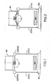
- a high resolution observation satellite in a visible wavelength range comprises a primary mirror M1 and a secondary mirror M2.
- the observation satellite, or telescope also comprises a BS support base, a STAV front structure, a CDRM2 support frame dedicated to the secondary mirror M2, and a BF input baffle to prevent solar inputs into the telescope.
- a plurality of LA support blades conventionally called spider blades, connect the frame CDRM2 of the secondary mirror M2 and the secondary mirror M2, the support strips LA being in the plane of the support frame CDRM2 of the secondary mirror M2, itself in the plane of the secondary mirror M2.
- the publication US 2006/018012 A1 describes a relevant observation craft.
- An object of the invention is to limit the inertia of such a spacecraft, so as to increase the agility of the spacecraft, without reducing the stability of the spacecraft so that it remains compatible with the quality image needed.
- an observation spacecraft comprising a primary mirror, a secondary mirror, a baffle a support base, and a support assembly of said secondary mirror, said support assembly comprising a support frame dedicated to the secondary mirror and comprised in a plane substantially parallel to the plane of the secondary mirror, and being provided with a plurality of support blades connecting the support frame of the secondary mirror and the secondary mirror, characterized in that the support blades are inclined with respect to the plane of the support frame of the secondary mirror, and at least a part of the secondary mirror is arranged inside the entrance cabinet.
- an observation satellite incorporating the invention can be made so that the support frame dedicated to the secondary mirror is closer to the support base, which implies a decrease in the inertia of the satellite.
- the support frame dedicated to the secondary mirror being closer to the support base, the inertia of the satellite is decreased, and the input cabinet can be brought closer to the primary mirror, which further improves the gain in inertia of the observation spacecraft.
- said inclination of the support blades connecting the secondary mirror frame and the secondary mirror is between 5 ° and 45 °.
- said inclination of the support blades connecting the frame of the secondary mirror and the secondary mirror is between 10 ° and 20 °, and for example substantially equal to 16 °.
- Such an embodiment corresponds to an optimization of the compromise between inertial gain of the observation space vehicle, and the optical stability of the secondary mirror.
- the support blades may comprise carbon fiber reinforced plastic or a ceramic material insensitive to the water environment and almost insensitive to thermal fluctuations.
- said ceramic material comprises silicon nitride.
- a high resolution observation satellite in a visible wavelength range comprises a primary mirror M1 and a secondary mirror M2.
- the satellite also includes a BS support base, a STAV front structure, a CDRM2 support frame dedicated to the secondary mirror M2, and a BF input cabinet.
- a plurality of LA support blades or spider blades connect the frame CDRM2 of the secondary mirror M2 and the secondary mirror M2, the support blades LA being inclined relative to the plane of the support frame CDRM2 of the secondary mirror M2, the plane of the mirror secondary M2 and the plane of its dedicated support frame CDRM2 being substantially parallel.
- the support assembly according to the invention is fixedly mounted so that the primary mirror M1 and the secondary mirror M2 are located on either side of the plane of the support frame CDRM2 of the secondary mirror M2.
- the inclination ⁇ of the support blades LA relative to the plane of the support frame CDRM2 of the secondary mirror M2 is between 5 ° and 45 °.
- the inclination ⁇ of the spider blades LA may be substantially equal to 16 °, which corresponds to an optimization of the compromise between the inertial gain of the observation spacecraft, and the stability optical secondary mirror M2.
- a good optimization corresponds to an inclination ⁇ of the spider blades LA substantially between 10 ° and 20 °.
- the support frame CDRM2 dedicated to the secondary mirror M2 is closer to the support base BS, which implies a decrease in the inertia of the satellite, and the input baffle BF can be brought closer to the primary mirror M1, which improves still the gain in inertia of the observation satellite.
- the LA support blades may comprise plastic with carbon fiber reinforcement or a ceramic material insensitive to the water environment and insensitive to thermal variations.
- the ceramic material may, for example, comprise silicon nitride. This limits the tilt that can be generated by the inclination ⁇ of the spider blades, for example of the order of 4 ⁇ rad.
- the design of such a secondary mirror support assembly for observation spacecraft can significantly reduce the inertia of the spacecraft, while avoiding to reduce the stability of the spacecraft so that It remains compatible with the image quality necessary for an observation in a visible wavelength range.
Landscapes
- Physics & Mathematics (AREA)
- Engineering & Computer Science (AREA)
- General Physics & Mathematics (AREA)
- Remote Sensing (AREA)
- Astronomy & Astrophysics (AREA)
- Optics & Photonics (AREA)
- Aviation & Aerospace Engineering (AREA)
- Telescopes (AREA)
- Mounting And Adjusting Of Optical Elements (AREA)
Description
- La présente invention porte sur un engin spatial d'observation.
- Les engins spatiaux de type satellites d'observation de haute résolution dans un domaine de longueurs d'onde visibles, sont équipés de miroirs embarqués de grande dimensions pouvant typiquement être des structures d'envergure supérieure à un mètre et d'épaisseur de l'ordre de quelques centimètres. Ces engins spatiaux et leurs éléments subissent de fortes variations de températures lors du fonctionnement opérationnel en orbite, et de très fortes contraintes mécaniques los de la phase de lancement depuis le sol jusqu'à leur station dans l'espace.
- De tels engins spatiaux ont une agilité ou maniabilité limitée, notamment due aux importantes inerties de tangage et de roulis.
- Une telle réalisation entraine de fortes instabilités en termes de tilt du miroir secondaire ainsi qu'une obturation importante liée à la nécessité d'avoir une structure du tripode suffisamment rigide pour supporter les environnements dynamiques lors du lancement.
- Tel qu'illustré sur la
figure 1 , en vue de coupe, un satellite d'observation de haute résolution dans un domaine de longueurs d'onde visibles comprend un miroir primaire M1 et un miroir secondaire M2. Le satellite d'observation, ou télescope, comprend également une base de support BS, une structure avant STAV, un cadre de support CDRM2 dédié au miroir secondaire M2, et un baffle d'entrée BF pour éviter les entrées solaires dans le télescope. Une pluralité de lames de support LA classiquement nommées lames araignée, relient le cadre CDRM2 du miroir secondaire M2 et le miroir secondaire M2, les lames de support LA étant dans le plan du cadre de support CDRM2 du miroir secondaire M2, lui-même dans le plan du miroir secondaire M2. La publicationUS 2006/018012 A1 décrit un engin d'observation pertinent. - Un but de l'invention est de limiter les inerties d'un tel engin spatial, de manière à augmenter l'agilité de l'engin spatial, sans réduire la stabilité de l'engin spatial pour que celle-ci reste compatible avec la qualité d'image nécessaire.
- Il est proposé, selon un aspect de l'invention, un engin spatial d'observation comprenant un miroir primaire, un miroir secondaire, un baffle d'entrée, une base de support, et un ensemble de support dudit miroir secondaire, ledit ensemble de support comprenant un cadre de support dédié au miroir secondaire et compris dans un plan sensiblement parallèle au plan du miroir secondaire, et étant muni d'une pluralité de lames de support reliant le cadre de support du miroir secondaire et le miroir secondaire, caractérisé en ce que les lames de support sont inclinées par rapport au plan du cadre de support du miroir secondaire, et au moins une partie du miroir secondaire est disposée à l'intérieur du baffle d'entrée.
- Ainsi, pour une configuration identique, un satellite d'observation intégrant l'invention peut être réalisé de façon que le cadre de support dédié au miroir secondaire soit plus proche de la base de support, ce qui implique une diminution de l'inertie du satellite. Aussi, le cadre de support dédié au miroir secondaire étant plus proche de la base de support, l'inertie du satellite est diminuée, et le baffle d'entrée peut être rapproché du miroir primaire, ce qui améliore encore le gain en inertie de l'engin spatial d'observation.
- Selon un mode de réalisation, ladite inclinaison des lames de support reliant le cadre du miroir secondaire et le miroir secondaire est comprise entre 5° et 45°.
- De telles valeurs permettent d'avoir un gain significatif en inertie (inclinaison supérieure ou égale à environ 5°), tout en évitant une instabilité du miroir secondaire et un risque d'obturation (inclinaison inférieure ou égale à environ 45°).
- Dans un mode de réalisation, ladite- inclinaison des lames de support reliant le cadre du miroir secondaire et le miroir secondaire est comprise entre 10° et 20°, et par exemple sensiblement égale à 16°.
- Un tel mode de réalisation correspond à une optimisation du compromis entre gain en inertie de l'engin spatial d'observation, et la stabilité optique du miroir secondaire.
- Lesdites lames de support peuvent comprendre du plastique à renfort fibre de carbone ou un matériau céramique insensible à l'environnement hydrique et quasiment insensible aux fluctuations thermiques.
- Par exemple, ledit matériau céramique comprend du Nitrure de Silicium.
- On limite ainsi le tilt du miroir secondaire pouvant être généré par l'inclinaison des lames d'araignée.
- L'invention sera mieux comprise à l'étude de quelques modes de réalisation décrits à titre d'exemples nullement limitatifs et illustrés par les dessins annexés sur lesquels :
- la
figure 1 illustre un satellite d'observation de l'état de la technique ; et - la
figure 2 illustre un satellite d'observation, comprenant selon un aspect de l'invention. - Sur l'ensemble de figures, les éléments ayants les mêmes références sont similaires.
- Tel qu'illustré sur la
figure 2 , en vue de coupe, un satellite d'observation de haute résolution dans un domaine de longueurs d'onde visibles comprend un miroir primaire M1 et un miroir secondaire M2. Le satellite comprend également une base de support BS, une structure avant STAV, un cadre de support CDRM2 dédié au miroir secondaire M2, et un baffle d'entrée BF. Une pluralité de lames de support LA ou lames araignée, relient le cadre CDRM2 du miroir secondaire M2 et le miroir secondaire M2, les lames de support LA étant inclinées par rapport au plan du cadre de support CDRM2 du miroir secondaire M2, le plan du miroir secondaire M2 et le plan de son cadre de support dédié CDRM2 étant sensiblement parallèles. Considérant la base de support et le miroir primaire M1 comme le bas du satellite d'observation, l'ensemble de support selon l'invention est monté fixement de sorte que les miroirs primaire M1 et secondaire M2 sont situés de part et d'autre du plan du cadre de support CDRM2 du miroir secondaire M2. - L'inclinaison α des lames de support LA par rapport au plan du cadre de support CDRM2 du miroir secondaire M2 est comprise entre 5° et 45°. Ainsi, on peut avoir un gain significatif en inertie car l'inclinaison α est supérieure ou égale à environ 5°, tout en évitant une instabilité du miroir secondaire et un risque d'obturation, car l'inclinaison α est inférieure ou égale à environ 45°.
- Par exemple, l'inclinaison α des lames araignée LA peut être sensiblement égale à 16°, ce qui correspond à une optimisation du compromis entre gain en inertie de l'engin spatial d'observation, et la stabilité optique du miroir secondaire M2. De manière un peu plus générale, une bonne optimisation correspond à une inclinaison α des lames araignée LA sensiblement comprise entre 10° et 20°.
- Le cadre de support CDRM2 dédié au miroir secondaire M2 est plus proche de la base de support BS, ce qui implique une diminution de l'inertie du satellite, et le baffle d'entrée BF peut être rapproché du miroir primaire M1, ce qui améliore encore le gain en inertie du satellite d'observation.
- Par exemple, pour un rapprochement du cadre de support CDRM2 de 15% de la base de support BS, un gain de l'ordre de 8% peut être gagné en inertie pour le satellite, par rapport à une structure en tripode pyramidal classique.
- Les lames de support LA peuvent comprendre du plastique à renfort fibre de carbone ou un matériau céramique insensible à l'environnement hydrique et peu sensible aux variations thermiques. Le matériau céramique peut, par exemple, comprendre du Nitrure de Silicium. On limite ainsi le tilt pouvant être généré par l'inclinaison α des lames d'araignée, par exemple de l'ordre de 4µrad.
- Aussi la conception d'un tel ensemble de support de miroir secondaire pour engin spatial d'observation, permet de diminuer de manière significative l'inertie de l'engin spatial, tout en évitant de réduire la stabilité de l'engin spatial pour que celle-ci reste compatible avec la qualité d'image nécessaire pour une observation dans un domaine de longueurs d'onde visibles.
Claims (4)
- Engin spatial d'observation comprenant un miroir primaire (M1), un miroir secondaire (M2), un baffle d'entrée (BF), une base de support (BS), et un ensemble de support dudit miroir secondaire (M2), ledit ensemble de support comprenant un cadre de support (CDRM2) dédié au miroir secondaire (M2) et compris dans un plan sensiblement parallèle au plan du miroir secondaire (M2), et étant muni d'une pluralité de lames de support (LA) reliant le cadre de support (CDRM2) du miroir secondaire (M2) et le miroir secondaire (M2), caractérisé en ce que les lames de support (LA) sont inclinées par rapport au plan du cadre de support (CDRM2) du miroir secondaire (M2), et au moins une partie du miroir secondaire (M2) est disposée à l'intérieur du baffle d'entrée (BF), l'inclinaison (α) des lames de support (LA) étant comprise entre 10° et 20°.
- Engin spatial d'observation selon la revendication 1, dans lequel ladite inclinaison (α) des lames de support (LA) est sensiblement égale à 16°.
- Engin spatial d'observation selon l'une des revendications 1 à 2, dans lequel lesdites lames de support (LA) comprennent du plastique à renfort fibre de carbone ou un matériau céramique insensible à l'environnement hydrique et quasiment insensible aux variations thermiques.
- Engin spatial d'observation selon la revendication 3, dans lequel ledit matériau céramique comprend du Nitrure de Silicium.
Applications Claiming Priority (1)
| Application Number | Priority Date | Filing Date | Title |
|---|---|---|---|
| FR0807006A FR2939912B1 (fr) | 2008-12-12 | 2008-12-12 | Ensemble de support d'un miroir secondaire d'un engin spatial d'observation de haute stabilite et a faible inertie mecanique |
Publications (3)
| Publication Number | Publication Date |
|---|---|
| EP2202553A1 EP2202553A1 (fr) | 2010-06-30 |
| EP2202553B1 EP2202553B1 (fr) | 2015-08-19 |
| EP2202553B3 true EP2202553B3 (fr) | 2018-06-27 |
Family
ID=40627435
Family Applications (1)
| Application Number | Title | Priority Date | Filing Date |
|---|---|---|---|
| EP09178813.3A Active EP2202553B3 (fr) | 2008-12-12 | 2009-12-11 | Télescope spatial de haute stabilité et à faible inertie |
Country Status (2)
| Country | Link |
|---|---|
| EP (1) | EP2202553B3 (fr) |
| FR (1) | FR2939912B1 (fr) |
Families Citing this family (1)
| Publication number | Priority date | Publication date | Assignee | Title |
|---|---|---|---|---|
| FR3041940B1 (fr) * | 2015-10-02 | 2018-07-13 | Airbus Defence And Space Sas | Satellite a corps principal cylindrique, empilement comprenant un tel satellite et ensemble de lancement pour un tel satellite |
Family Cites Families (3)
| Publication number | Priority date | Publication date | Assignee | Title |
|---|---|---|---|---|
| EP0610399A1 (fr) * | 1991-10-29 | 1994-08-17 | United Technologies Corporation | Structure ceramique monolithe en treillis |
| JP3058000B2 (ja) * | 1994-02-28 | 2000-07-04 | キヤノン株式会社 | ミラー光学装置 |
| US20060018012A1 (en) * | 2004-07-26 | 2006-01-26 | Smith John E | Apparatus and methods for focusing and collimating telescopes |
-
2008
- 2008-12-12 FR FR0807006A patent/FR2939912B1/fr active Active
-
2009
- 2009-12-11 EP EP09178813.3A patent/EP2202553B3/fr active Active
Also Published As
| Publication number | Publication date |
|---|---|
| FR2939912A1 (fr) | 2010-06-18 |
| FR2939912B1 (fr) | 2011-04-15 |
| EP2202553B1 (fr) | 2015-08-19 |
| EP2202553A1 (fr) | 2010-06-30 |
Similar Documents
| Publication | Publication Date | Title |
|---|---|---|
| EP2583900B1 (fr) | Carénage aérodynamique arrière pour dispositif d'accrochage d'un moteur d'aéronef, comprenant un bouclier thermique capable de se dilater librement | |
| EP3313734B1 (fr) | Satellite à corps principal cylindrique, empilement comprenant un tel satellite et ensemble de lancement pour un tel satellite | |
| EP3174794B2 (fr) | Satellite comprenant un instrument optique de prise de vue | |
| EP2469643A1 (fr) | Mat auto stable pour terrasse et procédé d'installation dudit mat | |
| EP1873061B1 (fr) | Structure déployable comportant des éléments rigides, embarquée sur un engin spatial | |
| EP2475866A1 (fr) | Moteur fusee a divergent deployable. | |
| EP2202553B1 (fr) | Télescope spatial de haute stabilité et à faible inertie | |
| EP2290430B1 (fr) | Dispositif de mesure de bougé de ligne de visée d'instrument optique | |
| EP4066037B1 (fr) | Instrument optique spatial comprenant une garde thermique améliorée | |
| FR3013679A1 (fr) | Carenage aerodynamique divise en sous-parties | |
| EP3259188B1 (fr) | Satellite artificiel | |
| EP1955975A1 (fr) | Dispositif télescopique de manutention | |
| WO2002103139A1 (fr) | Pylone monotube haubanne pour support d'antennes de telecommunications | |
| EP1955100B1 (fr) | Instrument optique comprenant une cavite d'entree dans laquelle est place un miroir | |
| EP3624255B1 (fr) | Ensemble de guidage d'ondes radioélectriques et antenne comprenant un tel ensemble | |
| FR2812271A1 (fr) | Satellite comprenant un instrument d'observation et un pare-soleil decouples l'un de l'autre | |
| FR3106778A1 (fr) | Treuil de désembourbage à montage latéral, et procédé de fabrication | |
| FR3087903A1 (fr) | Composant optique a filtre | |
| WO2025248188A1 (fr) | Dispositif optique astronomique et télescope associé | |
| EP4078268A1 (fr) | Joint de protection | |
| WO2011110555A1 (fr) | Ecran rayonnant pour tube a collecteur rayonnant | |
| EP2715100A1 (fr) | Système de réduction de la dynamique du segment mobile d'une tuyère déployable pour moteur de fusée | |
| FR3122262A1 (fr) | Télescope compact pour la détection de débris spatiaux | |
| FR3105178A1 (fr) | Structure porteuse pour véhicule spatial et procédé de montage d’une structure porteuse pour véhicule spatial | |
| WO2005081357A1 (fr) | Plateforme pour pylone de diffusion hertzienne et pylone de diffusion hertzienne muni d’une telle plateforme |
Legal Events
| Date | Code | Title | Description |
|---|---|---|---|
| PUAI | Public reference made under article 153(3) epc to a published international application that has entered the european phase |
Free format text: ORIGINAL CODE: 0009012 |
|
| AK | Designated contracting states |
Kind code of ref document: A1 Designated state(s): AT BE BG CH CY CZ DE DK EE ES FI FR GB GR HR HU IE IS IT LI LT LU LV MC MK MT NL NO PL PT RO SE SI SK SM TR |
|
| AX | Request for extension of the european patent |
Extension state: AL BA RS |
|
| 17P | Request for examination filed |
Effective date: 20101122 |
|
| 17Q | First examination report despatched |
Effective date: 20110414 |
|
| RIC1 | Information provided on ipc code assigned before grant |
Ipc: G02B 23/02 20060101ALN20150220BHEP Ipc: B64G 1/10 20060101ALI20150220BHEP Ipc: G02B 7/182 20060101AFI20150220BHEP Ipc: G02B 7/183 20060101ALN20150220BHEP |
|
| GRAP | Despatch of communication of intention to grant a patent |
Free format text: ORIGINAL CODE: EPIDOSNIGR1 |
|
| INTG | Intention to grant announced |
Effective date: 20150410 |
|
| GRAS | Grant fee paid |
Free format text: ORIGINAL CODE: EPIDOSNIGR3 |
|
| GRAA | (expected) grant |
Free format text: ORIGINAL CODE: 0009210 |
|
| AK | Designated contracting states |
Kind code of ref document: B1 Designated state(s): AT BE BG CH CY CZ DE DK EE ES FI FR GB GR HR HU IE IS IT LI LT LU LV MC MK MT NL NO PL PT RO SE SI SK SM TR |
|
| REG | Reference to a national code |
Ref country code: GB Ref legal event code: FG4D Free format text: NOT ENGLISH |
|
| REG | Reference to a national code |
Ref country code: CH Ref legal event code: EP |
|
| REG | Reference to a national code |
Ref country code: IE Ref legal event code: FG4D Free format text: LANGUAGE OF EP DOCUMENT: FRENCH |
|
| REG | Reference to a national code |
Ref country code: AT Ref legal event code: REF Ref document number: 744212 Country of ref document: AT Kind code of ref document: T Effective date: 20150915 |
|
| REG | Reference to a national code |
Ref country code: DE Ref legal event code: R096 Ref document number: 602009032969 Country of ref document: DE |
|
| REG | Reference to a national code |
Ref country code: FR Ref legal event code: PLFP Year of fee payment: 7 |
|
| REG | Reference to a national code |
Ref country code: AT Ref legal event code: MK05 Ref document number: 744212 Country of ref document: AT Kind code of ref document: T Effective date: 20150819 |
|
| REG | Reference to a national code |
Ref country code: LT Ref legal event code: MG4D |
|
| REG | Reference to a national code |
Ref country code: NL Ref legal event code: MP Effective date: 20150819 |
|
| PG25 | Lapsed in a contracting state [announced via postgrant information from national office to epo] |
Ref country code: FI Free format text: LAPSE BECAUSE OF FAILURE TO SUBMIT A TRANSLATION OF THE DESCRIPTION OR TO PAY THE FEE WITHIN THE PRESCRIBED TIME-LIMIT Effective date: 20150819 Ref country code: LV Free format text: LAPSE BECAUSE OF FAILURE TO SUBMIT A TRANSLATION OF THE DESCRIPTION OR TO PAY THE FEE WITHIN THE PRESCRIBED TIME-LIMIT Effective date: 20150819 Ref country code: LT Free format text: LAPSE BECAUSE OF FAILURE TO SUBMIT A TRANSLATION OF THE DESCRIPTION OR TO PAY THE FEE WITHIN THE PRESCRIBED TIME-LIMIT Effective date: 20150819 Ref country code: GR Free format text: LAPSE BECAUSE OF FAILURE TO SUBMIT A TRANSLATION OF THE DESCRIPTION OR TO PAY THE FEE WITHIN THE PRESCRIBED TIME-LIMIT Effective date: 20151120 Ref country code: NO Free format text: LAPSE BECAUSE OF FAILURE TO SUBMIT A TRANSLATION OF THE DESCRIPTION OR TO PAY THE FEE WITHIN THE PRESCRIBED TIME-LIMIT Effective date: 20151119 |
|
| PG25 | Lapsed in a contracting state [announced via postgrant information from national office to epo] |
Ref country code: AT Free format text: LAPSE BECAUSE OF FAILURE TO SUBMIT A TRANSLATION OF THE DESCRIPTION OR TO PAY THE FEE WITHIN THE PRESCRIBED TIME-LIMIT Effective date: 20150819 Ref country code: SE Free format text: LAPSE BECAUSE OF FAILURE TO SUBMIT A TRANSLATION OF THE DESCRIPTION OR TO PAY THE FEE WITHIN THE PRESCRIBED TIME-LIMIT Effective date: 20150819 Ref country code: PL Free format text: LAPSE BECAUSE OF FAILURE TO SUBMIT A TRANSLATION OF THE DESCRIPTION OR TO PAY THE FEE WITHIN THE PRESCRIBED TIME-LIMIT Effective date: 20150819 Ref country code: IS Free format text: LAPSE BECAUSE OF FAILURE TO SUBMIT A TRANSLATION OF THE DESCRIPTION OR TO PAY THE FEE WITHIN THE PRESCRIBED TIME-LIMIT Effective date: 20151219 Ref country code: ES Free format text: LAPSE BECAUSE OF FAILURE TO SUBMIT A TRANSLATION OF THE DESCRIPTION OR TO PAY THE FEE WITHIN THE PRESCRIBED TIME-LIMIT Effective date: 20150819 Ref country code: PT Free format text: LAPSE BECAUSE OF FAILURE TO SUBMIT A TRANSLATION OF THE DESCRIPTION OR TO PAY THE FEE WITHIN THE PRESCRIBED TIME-LIMIT Effective date: 20151221 |
|
| PG25 | Lapsed in a contracting state [announced via postgrant information from national office to epo] |
Ref country code: NL Free format text: LAPSE BECAUSE OF FAILURE TO SUBMIT A TRANSLATION OF THE DESCRIPTION OR TO PAY THE FEE WITHIN THE PRESCRIBED TIME-LIMIT Effective date: 20150819 |
|
| PG25 | Lapsed in a contracting state [announced via postgrant information from national office to epo] |
Ref country code: SK Free format text: LAPSE BECAUSE OF FAILURE TO SUBMIT A TRANSLATION OF THE DESCRIPTION OR TO PAY THE FEE WITHIN THE PRESCRIBED TIME-LIMIT Effective date: 20150819 Ref country code: EE Free format text: LAPSE BECAUSE OF FAILURE TO SUBMIT A TRANSLATION OF THE DESCRIPTION OR TO PAY THE FEE WITHIN THE PRESCRIBED TIME-LIMIT Effective date: 20150819 Ref country code: CZ Free format text: LAPSE BECAUSE OF FAILURE TO SUBMIT A TRANSLATION OF THE DESCRIPTION OR TO PAY THE FEE WITHIN THE PRESCRIBED TIME-LIMIT Effective date: 20150819 Ref country code: DK Free format text: LAPSE BECAUSE OF FAILURE TO SUBMIT A TRANSLATION OF THE DESCRIPTION OR TO PAY THE FEE WITHIN THE PRESCRIBED TIME-LIMIT Effective date: 20150819 |
|
| REG | Reference to a national code |
Ref country code: DE Ref legal event code: R097 Ref document number: 602009032969 Country of ref document: DE |
|
| PG25 | Lapsed in a contracting state [announced via postgrant information from national office to epo] |
Ref country code: BE Free format text: LAPSE BECAUSE OF NON-PAYMENT OF DUE FEES Effective date: 20151231 Ref country code: RO Free format text: LAPSE BECAUSE OF FAILURE TO SUBMIT A TRANSLATION OF THE DESCRIPTION OR TO PAY THE FEE WITHIN THE PRESCRIBED TIME-LIMIT Effective date: 20150819 |
|
| PLBE | No opposition filed within time limit |
Free format text: ORIGINAL CODE: 0009261 |
|
| 26N | No opposition filed |
Effective date: 20160520 |
|
| PG25 | Lapsed in a contracting state [announced via postgrant information from national office to epo] |
Ref country code: MC Free format text: LAPSE BECAUSE OF FAILURE TO SUBMIT A TRANSLATION OF THE DESCRIPTION OR TO PAY THE FEE WITHIN THE PRESCRIBED TIME-LIMIT Effective date: 20150819 Ref country code: LU Free format text: LAPSE BECAUSE OF FAILURE TO SUBMIT A TRANSLATION OF THE DESCRIPTION OR TO PAY THE FEE WITHIN THE PRESCRIBED TIME-LIMIT Effective date: 20151211 |
|
| REG | Reference to a national code |
Ref country code: CH Ref legal event code: PL |
|
| PG25 | Lapsed in a contracting state [announced via postgrant information from national office to epo] |
Ref country code: SI Free format text: LAPSE BECAUSE OF FAILURE TO SUBMIT A TRANSLATION OF THE DESCRIPTION OR TO PAY THE FEE WITHIN THE PRESCRIBED TIME-LIMIT Effective date: 20150819 |
|
| REG | Reference to a national code |
Ref country code: IE Ref legal event code: MM4A |
|
| PG25 | Lapsed in a contracting state [announced via postgrant information from national office to epo] |
Ref country code: LI Free format text: LAPSE BECAUSE OF NON-PAYMENT OF DUE FEES Effective date: 20151231 Ref country code: CH Free format text: LAPSE BECAUSE OF NON-PAYMENT OF DUE FEES Effective date: 20151231 Ref country code: IE Free format text: LAPSE BECAUSE OF NON-PAYMENT OF DUE FEES Effective date: 20151211 |
|
| REG | Reference to a national code |
Ref country code: FR Ref legal event code: PLFP Year of fee payment: 8 |
|
| PG25 | Lapsed in a contracting state [announced via postgrant information from national office to epo] |
Ref country code: SM Free format text: LAPSE BECAUSE OF FAILURE TO SUBMIT A TRANSLATION OF THE DESCRIPTION OR TO PAY THE FEE WITHIN THE PRESCRIBED TIME-LIMIT Effective date: 20150819 Ref country code: HU Free format text: LAPSE BECAUSE OF FAILURE TO SUBMIT A TRANSLATION OF THE DESCRIPTION OR TO PAY THE FEE WITHIN THE PRESCRIBED TIME-LIMIT; INVALID AB INITIO Effective date: 20091211 Ref country code: BG Free format text: LAPSE BECAUSE OF FAILURE TO SUBMIT A TRANSLATION OF THE DESCRIPTION OR TO PAY THE FEE WITHIN THE PRESCRIBED TIME-LIMIT Effective date: 20150819 |
|
| PG25 | Lapsed in a contracting state [announced via postgrant information from national office to epo] |
Ref country code: CY Free format text: LAPSE BECAUSE OF FAILURE TO SUBMIT A TRANSLATION OF THE DESCRIPTION OR TO PAY THE FEE WITHIN THE PRESCRIBED TIME-LIMIT Effective date: 20150819 |
|
| PG25 | Lapsed in a contracting state [announced via postgrant information from national office to epo] |
Ref country code: HR Free format text: LAPSE BECAUSE OF FAILURE TO SUBMIT A TRANSLATION OF THE DESCRIPTION OR TO PAY THE FEE WITHIN THE PRESCRIBED TIME-LIMIT Effective date: 20150819 |
|
| PG25 | Lapsed in a contracting state [announced via postgrant information from national office to epo] |
Ref country code: MT Free format text: LAPSE BECAUSE OF FAILURE TO SUBMIT A TRANSLATION OF THE DESCRIPTION OR TO PAY THE FEE WITHIN THE PRESCRIBED TIME-LIMIT Effective date: 20150819 |
|
| REG | Reference to a national code |
Ref country code: FR Ref legal event code: PLFP Year of fee payment: 9 |
|
| REG | Reference to a national code |
Ref country code: DE Ref legal event code: R055 Ref document number: 602009032969 Country of ref document: DE |
|
| PLCP | Request for limitation filed |
Free format text: ORIGINAL CODE: EPIDOSNLIM1 |
|
| PLCQ | Request for limitation of patent found admissible |
Free format text: ORIGINAL CODE: 0009231 |
|
| REG | Reference to a national code |
Ref country code: DE Ref legal event code: R081 Ref document number: 602009032969 Country of ref document: DE Owner name: THALES S.A., FR Free format text: FORMER OWNER: THALES, NEUILLY SUR SEINE, FR |
|
| LIM1 | Request for limitation found admissible |
Free format text: SEQUENCE NO: 1; FILED AFTER OPPOSITION PERIOD Filing date: 20171204 Effective date: 20171204 |
|
| PLCR | Communication despatched that request for limitation of patent was allowed |
Free format text: ORIGINAL CODE: 0009245 |
|
| REG | Reference to a national code |
Ref country code: DE Ref legal event code: R056 Ref document number: 602009032969 Country of ref document: DE Ref country code: DE Ref legal event code: R097 Ref document number: 602009032969 Country of ref document: DE |
|
| REG | Reference to a national code |
Ref country code: FR Ref legal event code: CA Effective date: 20180119 |
|
| PLCO | Limitation procedure: reply received to communication from examining division + time limit |
Free format text: ORIGINAL CODE: EPIDOSNLIR3 |
|
| PLCN | Payment of fee for limitation of patent |
Free format text: ORIGINAL CODE: EPIDOSNRAL3 |
|
| PUAM | (expected) publication of b3 document |
Free format text: ORIGINAL CODE: 0009410 |
|
| STAA | Information on the status of an ep patent application or granted ep patent |
Free format text: STATUS: THE PATENT HAS BEEN LIMITED |
|
| PG25 | Lapsed in a contracting state [announced via postgrant information from national office to epo] |
Ref country code: MK Free format text: LAPSE BECAUSE OF FAILURE TO SUBMIT A TRANSLATION OF THE DESCRIPTION OR TO PAY THE FEE WITHIN THE PRESCRIBED TIME-LIMIT Effective date: 20150819 |
|
| PGFP | Annual fee paid to national office [announced via postgrant information from national office to epo] |
Ref country code: TR Payment date: 20201209 Year of fee payment: 12 |
|
| PG25 | Lapsed in a contracting state [announced via postgrant information from national office to epo] |
Ref country code: TR Free format text: LAPSE BECAUSE OF NON-PAYMENT OF DUE FEES Effective date: 20211211 |
|
| PGFP | Annual fee paid to national office [announced via postgrant information from national office to epo] |
Ref country code: DE Payment date: 20241120 Year of fee payment: 16 |
|
| PGFP | Annual fee paid to national office [announced via postgrant information from national office to epo] |
Ref country code: GB Payment date: 20241114 Year of fee payment: 16 |
|
| PGFP | Annual fee paid to national office [announced via postgrant information from national office to epo] |
Ref country code: IT Payment date: 20241128 Year of fee payment: 16 |
|
| PGFP | Annual fee paid to national office [announced via postgrant information from national office to epo] |
Ref country code: FR Payment date: 20251124 Year of fee payment: 17 |