EP2202535A1 - Radiometric electrical line sensor in combination with mechanical rotating mirror for creating 2D image - Google Patents
Radiometric electrical line sensor in combination with mechanical rotating mirror for creating 2D image Download PDFInfo
- Publication number
- EP2202535A1 EP2202535A1 EP08172714A EP08172714A EP2202535A1 EP 2202535 A1 EP2202535 A1 EP 2202535A1 EP 08172714 A EP08172714 A EP 08172714A EP 08172714 A EP08172714 A EP 08172714A EP 2202535 A1 EP2202535 A1 EP 2202535A1
- Authority
- EP
- European Patent Office
- Prior art keywords
- field
- view
- sensor
- line
- mirror
- Prior art date
- Legal status (The legal status is an assumption and is not a legal conclusion. Google has not performed a legal analysis and makes no representation as to the accuracy of the status listed.)
- Withdrawn
Links
Images



Classifications
-
- H—ELECTRICITY
- H01—ELECTRIC ELEMENTS
- H01Q—ANTENNAS, i.e. RADIO AERIALS
- H01Q3/00—Arrangements for changing or varying the orientation or the shape of the directional pattern of the waves radiated from an antenna or antenna system
- H01Q3/12—Arrangements for changing or varying the orientation or the shape of the directional pattern of the waves radiated from an antenna or antenna system using mechanical relative movement between primary active elements and secondary devices of antennas or antenna systems
- H01Q3/16—Arrangements for changing or varying the orientation or the shape of the directional pattern of the waves radiated from an antenna or antenna system using mechanical relative movement between primary active elements and secondary devices of antennas or antenna systems for varying relative position of primary active element and a reflecting device
- H01Q3/20—Arrangements for changing or varying the orientation or the shape of the directional pattern of the waves radiated from an antenna or antenna system using mechanical relative movement between primary active elements and secondary devices of antennas or antenna systems for varying relative position of primary active element and a reflecting device wherein the primary active element is fixed and the reflecting device is movable
-
- G—PHYSICS
- G01—MEASURING; TESTING
- G01S—RADIO DIRECTION-FINDING; RADIO NAVIGATION; DETERMINING DISTANCE OR VELOCITY BY USE OF RADIO WAVES; LOCATING OR PRESENCE-DETECTING BY USE OF THE REFLECTION OR RERADIATION OF RADIO WAVES; ANALOGOUS ARRANGEMENTS USING OTHER WAVES
- G01S13/00—Systems using the reflection or reradiation of radio waves, e.g. radar systems; Analogous systems using reflection or reradiation of waves whose nature or wavelength is irrelevant or unspecified
- G01S13/88—Radar or analogous systems specially adapted for specific applications
- G01S13/887—Radar or analogous systems specially adapted for specific applications for detection of concealed objects, e.g. contraband or weapons
-
- G—PHYSICS
- G03—PHOTOGRAPHY; CINEMATOGRAPHY; ANALOGOUS TECHNIQUES USING WAVES OTHER THAN OPTICAL WAVES; ELECTROGRAPHY; HOLOGRAPHY
- G03B—APPARATUS OR ARRANGEMENTS FOR TAKING PHOTOGRAPHS OR FOR PROJECTING OR VIEWING THEM; APPARATUS OR ARRANGEMENTS EMPLOYING ANALOGOUS TECHNIQUES USING WAVES OTHER THAN OPTICAL WAVES; ACCESSORIES THEREFOR
- G03B37/00—Panoramic or wide-screen photography; Photographing extended surfaces, e.g. for surveying; Photographing internal surfaces, e.g. of pipe
-
- H—ELECTRICITY
- H01—ELECTRIC ELEMENTS
- H01Q—ANTENNAS, i.e. RADIO AERIALS
- H01Q19/00—Combinations of primary active antenna elements and units with secondary devices, e.g. with quasi-optical devices, for giving the antenna a desired directional characteristic
- H01Q19/10—Combinations of primary active antenna elements and units with secondary devices, e.g. with quasi-optical devices, for giving the antenna a desired directional characteristic using reflecting surfaces
- H01Q19/104—Combinations of primary active antenna elements and units with secondary devices, e.g. with quasi-optical devices, for giving the antenna a desired directional characteristic using reflecting surfaces using a substantially flat reflector for deflecting the radiated beam, e.g. periscopic antennas
Definitions
- the present invention relates to the field of two dimensional (2D) radiometric imaging.
- the present invention especially relates to a sensor unit.
- Radiometric imaging uses electromagnetic radiation to obtain images of any kind of object. Radiometric imaging is used in a multitude if applications including military, surveillance/security, geometric, geologic, and industrial applications. By using different frequencies/wavelength, different images can be obtained and different properties of imaged objects can be obtained.
- the wavelengths ranging from of 1000 mm to 1 mm are commonly referred to as microwaves. Other definitions cite 300 mm for the upper bound of the microwave spectrum and 10 mm for the lower bound.
- Electromagnetic radiation in the range from 100 mm to 10 mm is commonly referred as centimeter waves and radiation in the range from 10 mm to 1 mm is commonly referred to millimeter waves.
- Submillimeter waves are commonly seen as ranging from 1 mm to 0.1 mm, but may also comprise still smaller wavelengths from the far infrared. Submillimeter waves are also referred to as Terahertz radiation. The smaller the wavelength, the higher is the attainable resolution. Microwaves, millimeter waves and submillimeter waves penetrate e.g. clothes any may be used to detect objects carried by human beings under the clothes.
- Active and passive sensor are known. Active sensors (e.g. radar sensors) do emit electromagnetic radiation and detect reflected radiation (response radiation), whereas passive sensors do not emit electromagnetic radiation and do detect radiation emitted by a sensed object. Passive sensor may, for example, detect black body radiation emitted by an object due to its temperature according to Planck's law.
- Active sensors e.g. radar sensors
- passive sensors do not emit electromagnetic radiation and do detect radiation emitted by a sensed object.
- Passive sensor may, for example, detect black body radiation emitted by an object due to its temperature according to Planck's law.
- a 2D image By mounting such systems on moving objects like planes, helicopters or satellites, a 2D image can be created.
- the 2D image is created out of the rotation of the mirror and the movement of the sensor itself.
- phased array antennas Another known technique for creating a 2D image is fully electronic scanning using e.g. phased array antennas. These kind of antennas are created out of a high number of single sensors arranged in two dimensions. The array may extends tens of centimeters or even some meters in both of the two dimensions. The number of single sensors is directly related to the resolution of the phased array. The single sensors are operated with individual signals having a specific phase relation to each other in order to achieve a specific direction of the antenna beam. Each direction corresponds to a specific phase combination. Phased array antennas offer high flexibility but the high number of single sensors and the electronic circuit for providing the phase relations makes this design very complex and expensive.
- the sensor unit comprises a reflecting element mounted so as to be rotatable around an axis of rotation and a line sensor operating in the microwave, millimeter wave and/or terahertz frequency range and having its field of view directed towards the reflecting element, whereby the axis of rotation intersects with a reflection plane of the reflecting element.
- a 2D image can be obtained using a relatively small and inexpensive 1D line sensor.
- the size, cost and complexity of the sensor unit is small compared to the prior art.
- the axis of rotation is parallel to a field of view plane of the line sensor.
- the line sensor is mounted on the axis of rotation.
- the line sensor is adapted to electrically scan its field of view.
- the line sensor is a frequency sweeping line sensor.
- the sensor unit further comprises an image processor for compensating an inclination of the reflected field of view plane due to a rotation of the reflective element.
- the sensor unit further comprises one or more further line sensors operating in the microwave, millimeter wave and/or terahertz frequency range and having the respective one or more fields of view directed towards the reflective element, whereby the field of view plane of each line sensor intersects with the field of view plane of each other line sensor.
- the n field of view planes of the n line sensors are advantageously provided at an angular distance ⁇ 180°/ n .
- Fig. 1 shows a first embodiment of the sensor unit according to the present invention.
- the sensor unit 1 comprises a fixed mounted line sensor 1 and a rotating reflective element 2, in the following termed "mirror".
- the mirror 2 as depicted is of rectangular shape, but a circularly or elliptically or otherwise shaped mirror 2 is possible to.
- the mirror may have a flat (as depicted) or may have a curved reflecting surface. When the mirror is flat, the reflecting surface of the mirror 2 is (defines) a reflection plane of the mirror 2. When the mirror is not flat but curved, the principal plane of the mirror 2 is (defines) a reflection of the mirror 2.
- the line sensor 2 operates in the microwave, millimeter wave and/or Terahertz frequency range and is arranged so as to view reflections in the mirror 2.
- the mirror 2 is reflective for the wavelengths of the range of operation of the line sensor 1.
- the mirror may be or be made from a metal, a meta material or a mirror (in the narrow sense).
- a motor 3 comprising a fixed mounted part 3a and a movable part 3b is provided.
- the fixed mounted motor part 3a and the movable (rotatable) motor part 3b are of annular shape but other configurations are possible.
- the mirror 2 is fixed to the movable part 3b with two supporting elements 5.
- the supporting elements 5 are of cylindrical shape with one end attached to the movable part 3b and the other end attached to the mirror 2.
- the supporting elements 5 are arranged in diametrical opposition on the annular shaped movable motor part 3b.
- a right handed Cartesian coordinate system with coordinate axes x, y, and z.
- the x- and y-axes correspond to horizontal directions and the z-axis correspond to the vertical direction.
- the movable motor part 4 and the mirror 2 are rotatable around an axis of rotation 6 which coincides with the z-axis.
- the axis of rotation 6 intersects with the mirror 2 (intersects with the reflection plane of the mirror 2).
- the mirror 2 (the reflection plane) might intersect with the rotation axis 6 at any angle ⁇ between 0° exclusive and 90° exclusive (see Fig. 2 for a definition of the angle ⁇ ).
- the mirror 2 has to be very large and when the angle is very large, the motor parts 3a, 3b and/or the line sensor 1 might block the sensor's field of view.
- the axis of rotation 6 passes through the center of the annular movable motor part 3b and the center of the annular fixed motor part 3a.
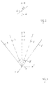
- Fig. 3 illustrates the field of view of the sensor 1. While the field of view of a line sensor is often referred as one dimensional, the notion 'field of view' is also used indicate the two dimensional area within which radiation from a sensed object or from infinity travels to the line sensor 1. This two dimensional area (the field of view) defines and lies within a plane which is called the field of view plane. In the embodiment, the field of view lies within the vertical y-z-plane. The y-z-plane is the field of view plane of the line sensor 1. Generally, it is possible however that the field of view deviates from the vertical.
- the field of view is of substantially conical shape and has an opening angle ⁇ .
- the field of view is composed of a plurality of antenna emission and/or reception patterns (antenna beams).
- the antenna beam width advantageously is very small (very narrow antenna beam) so that a high resolution is obtained.
- Each antenna beam has a different direction 7.
- Fig. 3 shows five antenna beam directions 7 only. Typically, a few tens, hundreds or even thousands of antenna beam directions 7 will be provided.
- Each antenna beam direction 7 corresponds to a pixel.
- an antenna beam direction might be varied continuously.
- the axis of rotation 6 lies in the center of the field of view. In other words, the axis of rotation 6 divides the field of view in two equal parts. Or, more generally, the field of view is mirror symmetrical in relation to the vertical x-z-plane. Generally, it is possible however that the field of view is not centered around the rotation axis 6 or the x-z-plane.
- the sensor 1 and the origin of all antenna beam directions 7 is located on the axis of rotation.
- the line sensor 1 might for example be a sweeping line sensor, in which one antenna beam direction 7 is sensed at a time. Sweeping advantageously is electric and not mechanic, since electric sweeping is faster and less error prone.
- the sensor 1 might be a well known frequency sweeping line sensor (frequency scanning antenna). Alternatively, all antenna beam directions 7 may be sensed simultaneously. This provides for even faster scanning but requires a more complex and more expensive sensor 1.
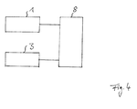
- the sensor unit comprises a processing and control unit 8 for controlling the operation of the line sensor 1 and the motor 3 as schematically depicted in Fig. 4 .
- a 360° panorama image of a region around the sensor unit can be obtained.
- the scanned region corresponds to a (closed) ribbon.
- the ribbon With the field of view arranged exactly as described above, the ribbon is substantially arranged horizontally. When - in departure thereof - the field of view plane is not vertical, the ribbon will deviate from the horizontal.
- Fig. 5 shows three image taking directions (corresponding to mirror rotation angles ⁇ ) 10.
- the first image taking direction 10-1 corresponds to a mirror rotation angle of 0° and is along the y-axis (more generally within the y-z plane).
- a first line 11-1 is scanned.
- the second image taking direction 10-2 corresponds to a mirror rotation angle ⁇ 1 larger than 0° and smaller than 90° (e.g. 45°).
- a second line 11-2 is scanned.
- a line 11-3 is scanned.
- the angle between the image taking direction 10 and the scanned line 11 changes the same amount.
- the angle between the picture taking direction 10 and the scanned line 11 is the same as the mirror rotation angle ⁇ .
- the scanning line 11-1 moves perpendicular to its extension and the scanning ribbon has maximum width.
- the scanning line 11-2 moves askew to its extension and the width of the scanning ribbon decreases.
- the scanning line 11-3 moves along its extension and the width of the scanning ribbon decreases (degenerates) to zero.
- the scanning ribbon has full width and at 270° the width decreases to zero.
- the scanning ribbon is said to have dead spots at 90° and 270°.
- a 2D image can be obtained using a small and inexpensive 1D line sensor.
- the size, cost and complexity of the sensor unit is small compared to the prior art.
- the processing and control unit 8 may be adapted to compensate the variation of the angle between the image taking direction 10 and the scanned line 11 using image processing technology (hardware and/or software) so that a non distorted image is obtained.
- image processing technology hardware and/or software
- it can not compensate for the decrease of the ribbon width, that is, the scanned area is the same with or without compensation.
- the line sensor 1 might be operated with different field of width opening angles ⁇ depending on the mirror rotation angle ⁇ . Compensation by increasing the opening angle fails at and near the dead spots, however.
- the shape for the mirror 2 which provides for the least mirror area is an ellipse.
- the image area can be further reduced e.g. by adopting a bow tie shape.
- an elongated mirror of substantially rectangular form might be employed.
- the present invention proposes the use of two or more line sensors, which are disposed at an angle to each other. This provides for less reduction of the ribbon width and eliminates dead spots.
- Possible arrangements of the sensors and their field of views are depicted in Fig. 6 . Shown are up to three line sensors 21, 22, 23 identical to the line sensor 1 described above. Each line sensor has a conical field of view. The field of view planes of all sensors 21, 22, 23 are assumed to be vertical (parallel to or including the z-axis) and each field of view is assumed to be mirror symmetric in relation to a vertical plane. Generally, this need not be the case however.
- Each line sensor is indicated by a line.
- the orientation of the line indicates the orientation of the field of view.
- the center of the field of view (the origin of all antenna beam directions 7) is indicated by a dot.
- Each of the sensor's fields of view is oriented such that it receives electromagnetic radiation reflected by the mirror 2.
- the sensor 21 is arranged along the y-axis exactly as the line sensor 1 in the embodiment having only one line sensor 1.
- the center of the field of view of the first sensor 21 lies on the rotation axis 6 (i.e. the z-axis).
- the second line sensor 22 is arranged along the x-axis.
- the mirror 2 is in a dead spot position (90° or 270°) in relation to the sensor 21, the mirror is in optimum position (maximum ribbon width) in relation to the sensor 22. Therefore, the problem of dead spots is overcome.
- the sensor 21 is arranged along the y-axis and the sensor 22 is arranged along the x-axis.
- Both the center of the field of view of the first sensor 21 and the center of the field of view of the second sensor 22 lie on the rotation axis 6.
- the sensors 21, 22 are arranged at an angle ⁇ 90° and their field of view planes intersect at an angle ⁇ 90°. None of the field of view centers is located on the axis of rotation 6.
- the sensors 21, 22 are arranged at an angle ⁇ 90° and their field of view planes intersect at an angle ⁇ 90°. Both field of view centers are located on the axis of rotation 6.
- Each of the field of view centers is located on the axis of rotation 6.
- the sensors 21, 22, 23 are arranged at an angle ⁇ 60° and their field of view planes intersect at an angle ⁇ 60°.
- the arrangements b), d) and f), where the centers of each field of view lie on the rotation axis 6, have the advantage that the various ribbons are arranged substantially in the horizontal.
- Some of the configurations a), c), e) and g) may not be optimal in this respect.
- the arrangements c), d) and g), where the n field of view planes of the n line sensors are provided at an angular distance ⁇ 180°/ n have the advantage that they provide for the largest minimum ribbon width in a specific section of the ribbon for any arrangement of n line sensors.
- the arrangements a), b), e) and f), wherein the n field of view planes of the n line sensors are provided at equal angular distance ⁇ 180°/ n , have the advantage that they provide for the largest minimum ribbon width of any arrangement of n line sensors.
- the processing and control unit 8 advantageously is adapted to merge all the (image) information provided by the various line sensors 21, 22, 23 into a single 2D image (e.g. 360° panorama image).
- the mirror 2 is driven by the motor 3.
- the mirror 2 may for example be driven so as to rotate always in one direction (e.g. in embodiments where an images of small width ⁇ is taken) or may be driven so as to alternately rotate clockwise and anti-clockwise (e.g. in embodiments where images of wide widths ⁇ are taken).
- the mirror may for example be driven stepped (in accordance with line image taken by the line sensor 1) or be driven with constant angular speed (at least during the recording of an image).
- Still images and/or moving images may be obtained with the sensor unit.
Landscapes
- Physics & Mathematics (AREA)
- Engineering & Computer Science (AREA)
- Radar, Positioning & Navigation (AREA)
- Remote Sensing (AREA)
- General Physics & Mathematics (AREA)
- Electromagnetism (AREA)
- Computer Networks & Wireless Communication (AREA)
- Transforming Light Signals Into Electric Signals (AREA)
- Aerials With Secondary Devices (AREA)
- Photometry And Measurement Of Optical Pulse Characteristics (AREA)
- Variable-Direction Aerials And Aerial Arrays (AREA)
Abstract
The present invention relates to the field of two dimensional (2D) radiometric imaging. The present invention especially relates to a sensor unit. The sensor unit according to the present invention comprises a reflecting element mounted so as to be rotatable around an axis of rotation and a line sensor operating in the microwave, millimeter wave and/or terahertz frequency range and having its field of view directed towards the reflecting element, whereby the axis of rotation intersects with a reflection plane of the reflecting element.
Description
- The present invention relates to the field of two dimensional (2D) radiometric imaging. The present invention especially relates to a sensor unit.
- Radiometric imaging uses electromagnetic radiation to obtain images of any kind of object. Radiometric imaging is used in a multitude if applications including military, surveillance/security, geometric, geologic, and industrial applications. By using different frequencies/wavelength, different images can be obtained and different properties of imaged objects can be obtained. The wavelengths ranging from of 1000 mm to 1 mm are commonly referred to as microwaves. Other definitions cite 300 mm for the upper bound of the microwave spectrum and 10 mm for the lower bound. Electromagnetic radiation in the range from 100 mm to 10 mm is commonly referred as centimeter waves and radiation in the range from 10 mm to 1 mm is commonly referred to millimeter waves. Submillimeter waves are commonly seen as ranging from 1 mm to 0.1 mm, but may also comprise still smaller wavelengths from the far infrared. Submillimeter waves are also referred to as Terahertz radiation. The smaller the wavelength, the higher is the attainable resolution. Microwaves, millimeter waves and submillimeter waves penetrate e.g. clothes any may be used to detect objects carried by human beings under the clothes.
- In the optical region, cameras having a two dimensional field of view allowing to obtain an image of the object are well known and available at low prices. At other frequency regions of the electromagnetic spectrum, sensors operable to take a two dimensional image might not be available commercially or might be very expensive.
- Active and passive sensor are known. Active sensors (e.g. radar sensors) do emit electromagnetic radiation and detect reflected radiation (response radiation), whereas passive sensors do not emit electromagnetic radiation and do detect radiation emitted by a sensed object. Passive sensor may, for example, detect black body radiation emitted by an object due to its temperature according to Planck's law.
- It is well known to use a single pixel sensor in combination with a rotating mirror for creating a line scanner/sensor.
- By mounting such systems on moving objects like planes, helicopters or satellites, a 2D image can be created. Thus, the 2D image is created out of the rotation of the mirror and the movement of the sensor itself.
- Another known technique for creating a 2D image is fully electronic scanning using e.g. phased array antennas. These kind of antennas are created out of a high number of single sensors arranged in two dimensions. The array may extends tens of centimeters or even some meters in both of the two dimensions. The number of single sensors is directly related to the resolution of the phased array. The single sensors are operated with individual signals having a specific phase relation to each other in order to achieve a specific direction of the antenna beam. Each direction corresponds to a specific phase combination. Phased array antennas offer high flexibility but the high number of single sensors and the electronic circuit for providing the phase relations makes this design very complex and expensive.
- It is an object of the present invention to provide for an inexpensive sensor unit for taking a two dimensional image in the microwave, millimeter wave and/or Terahertz frequency range. This problem is solved by providing the sensor unit according to the present invention.
- The sensor unit according to the present invention comprises a reflecting element mounted so as to be rotatable around an axis of rotation and a line sensor operating in the microwave, millimeter wave and/or terahertz frequency range and having its field of view directed towards the reflecting element, whereby the axis of rotation intersects with a reflection plane of the reflecting element.
- Thus, a 2D image can be obtained using a relatively small and inexpensive 1D line sensor. The size, cost and complexity of the sensor unit is small compared to the prior art.
- Advantageously, the axis of rotation is parallel to a field of view plane of the line sensor.
- Advantageously, the line sensor is mounted on the axis of rotation.
- Advantageously, the line sensor is adapted to electrically scan its field of view.
- Advantageously, the line sensor is a frequency sweeping line sensor.
- Advantageously, the sensor unit further comprises an image processor for compensating an inclination of the reflected field of view plane due to a rotation of the reflective element.
- Advantageously, the sensor unit further comprises one or more further line sensors operating in the microwave, millimeter wave and/or terahertz frequency range and having the respective one or more fields of view directed towards the reflective element, whereby the field of view plane of each line sensor intersects with the field of view plane of each other line sensor. Hereby, when the number of line sensors is n, the n field of view planes of the n line sensors are advantageously provided at equal angular distance σ=180°/n. Alternatively, the n field of view planes of the n line sensors are advantageously provided at an angular distance σ≤180°/n.
-
-
Fig. 1 shows a first embodiment of the sensor unit according to the present invention. -
Fig. 2 shows the definition of a mirror inclination angle. -
Fig. 3 illustrates the field of view of the line sensor according to the first embodiment. -
Fig. 4 shows a schematic representation of the electronic components of the sensor unit. -
Fig. 5 illustrates operation of the sensor unit. -
Fig. 6 shows schematic arrangements of line sensor according to a further embodiment of the present invention. -
Fig. 1 shows a first embodiment of the sensor unit according to the present invention. Thesensor unit 1 comprises a fixed mountedline sensor 1 and a rotatingreflective element 2, in the following termed "mirror". Themirror 2 as depicted is of rectangular shape, but a circularly or elliptically or otherwiseshaped mirror 2 is possible to. The mirror may have a flat (as depicted) or may have a curved reflecting surface. When the mirror is flat, the reflecting surface of themirror 2 is (defines) a reflection plane of themirror 2. When the mirror is not flat but curved, the principal plane of themirror 2 is (defines) a reflection of themirror 2. Theline sensor 2 operates in the microwave, millimeter wave and/or Terahertz frequency range and is arranged so as to view reflections in themirror 2. Themirror 2 is reflective for the wavelengths of the range of operation of theline sensor 1. Eventually, the mirror may be or be made from a metal, a meta material or a mirror (in the narrow sense). A motor 3 comprising a fixed mounted part 3a and a movable part 3b is provided. The fixed mounted motor part 3a and the movable (rotatable) motor part 3b are of annular shape but other configurations are possible. Themirror 2 is fixed to the movable part 3b with two supporting elements 5. The supporting elements 5 are of cylindrical shape with one end attached to the movable part 3b and the other end attached to themirror 2. The supporting elements 5 are arranged in diametrical opposition on the annular shaped movable motor part 3b. As themirror 2 is rotatable and theline sensor 1 is fixed, themirror 2 is rotatable in relation to theline sensor 1. - Further shown is a right handed Cartesian coordinate system with coordinate axes x, y, and z. For the purpose of ease of explanation only, the x- and y-axes correspond to horizontal directions and the z-axis correspond to the vertical direction. The movable motor part 4 and the
mirror 2 are rotatable around an axis ofrotation 6 which coincides with the z-axis. The axis ofrotation 6 intersects with the mirror 2 (intersects with the reflection plane of the mirror 2). The mirror 2 (the reflection plane) might intersect with therotation axis 6 at any angle δ between 0° exclusive and 90° exclusive (seeFig. 2 for a definition of the angle δ). However, when the angle is very small, themirror 2 has to be very large and when the angle is very large, the motor parts 3a, 3b and/or theline sensor 1 might block the sensor's field of view. The axis ofrotation 6 passes through the center of the annular movable motor part 3b and the center of the annular fixed motor part 3a. -
Fig. 3 illustrates the field of view of thesensor 1. While the field of view of a line sensor is often referred as one dimensional, the notion 'field of view' is also used indicate the two dimensional area within which radiation from a sensed object or from infinity travels to theline sensor 1. This two dimensional area (the field of view) defines and lies within a plane which is called the field of view plane. In the embodiment, the field of view lies within the vertical y-z-plane. The y-z-plane is the field of view plane of theline sensor 1. Generally, it is possible however that the field of view deviates from the vertical. The field of view is of substantially conical shape and has an opening angle γ. The field of view is composed of a plurality of antenna emission and/or reception patterns (antenna beams). The antenna beam width advantageously is very small (very narrow antenna beam) so that a high resolution is obtained. Each antenna beam has adifferent direction 7. For ease of presentation,Fig. 3 shows fiveantenna beam directions 7 only. Typically, a few tens, hundreds or even thousands ofantenna beam directions 7 will be provided. Eachantenna beam direction 7 corresponds to a pixel. Also, an antenna beam direction might be varied continuously. The axis ofrotation 6 lies in the center of the field of view. In other words, the axis ofrotation 6 divides the field of view in two equal parts. Or, more generally, the field of view is mirror symmetrical in relation to the vertical x-z-plane. Generally, it is possible however that the field of view is not centered around therotation axis 6 or the x-z-plane. In this embodiment, thesensor 1 and the origin of allantenna beam directions 7 is located on the axis of rotation. - The
line sensor 1 might for example be a sweeping line sensor, in which oneantenna beam direction 7 is sensed at a time. Sweeping advantageously is electric and not mechanic, since electric sweeping is faster and less error prone. For example, thesensor 1 might be a well known frequency sweeping line sensor (frequency scanning antenna). Alternatively, allantenna beam directions 7 may be sensed simultaneously. This provides for even faster scanning but requires a more complex and moreexpensive sensor 1. - Advantageously, the sensor unit comprises a processing and control unit 8 for controlling the operation of the
line sensor 1 and the motor 3 as schematically depicted inFig. 4 . - The operation of the sensor unit is further explained in relation with
Fig. 5 . With the sensor unit, a 360° panorama image of a region around the sensor unit can be obtained. The scanned region corresponds to a (closed) ribbon. The higher the mirror inclination angle δ (the more themirror 2 is horizontal), the lower the imaged region will be located in relation to the sensor unit. With the field of view arranged exactly as described above, the ribbon is substantially arranged horizontally. When - in departure thereof - the field of view plane is not vertical, the ribbon will deviate from the horizontal. Similarly, when - in departure of the above described arrangement - the field of view is not mirror symmetric in relation to the x-z-plane or to a plane parallel to the x-z-plane, the ribbon will deviate from the horizontal. Finally, when the field of view is mirror symmetric in relation to a plane parallel to the x-z-plane but - in departure of the above described arrangement - is not mirror symmetric in relation to the x-z-plane, the ribbon will deviate from the horizontal. In the last case however, the departure from horizontal arrangement is small (negligible) when the imaged region is far and/or the mirror inclination angle δ is large. -
Fig. 5 shows three image taking directions (corresponding to mirror rotation angles α) 10. The first image taking direction 10-1 corresponds to a mirror rotation angle of 0° and is along the y-axis (more generally within the y-z plane). When in the first image taking direction 10-1, a first line 11-1 is scanned. The second image taking direction 10-2 corresponds to a mirror rotation angle α1 larger than 0° and smaller than 90° (e.g. 45°). When in the second image taking direction 10-2, a second line 11-2 is scanned. The third image taking direction 10-3 corresponds to a mirror rotation angle α2=90° and is along the x-axis (more generally within the x-z-plane). When in the third image taking direction, a line 11-3 is scanned. When themirror 2 is rotated, the angle between the image taking direction 10 and the scanned line 11 changes the same amount. In the convention used, the angle between the picture taking direction 10 and the scanned line 11 is the same as the mirror rotation angle α. - At 0°, the scanning line 11-1 moves perpendicular to its extension and the scanning ribbon has maximum width. When the mirror rotation angle α increases, the scanning line 11-2 moves askew to its extension and the width of the scanning ribbon decreases. At 90°, the scanning line 11-3 moves along its extension and the width of the scanning ribbon decreases (degenerates) to zero. Similarly, at 180° the scanning ribbon has full width and at 270° the width decreases to zero. The scanning ribbon is said to have dead spots at 90° and 270°.
- Thus, a 2D image can be obtained using a small and inexpensive 1D line sensor. The size, cost and complexity of the sensor unit is small compared to the prior art.
- The processing and control unit 8 may be adapted to compensate the variation of the angle between the image taking direction 10 and the scanned line 11 using image processing technology (hardware and/or software) so that a non distorted image is obtained. Of course, it can not compensate for the decrease of the ribbon width, that is, the scanned area is the same with or without compensation. In order to compensate for the decrease of ribbon width (and effectively provide a constant or more constant ribbon width), the
line sensor 1 might be operated with different field of width opening angles γ depending on the mirror rotation angle α. Compensation by increasing the opening angle fails at and near the dead spots, however. - The width of an image is given by the variation Δα of the mirror rotation angle α. It is envisaged that the above solution using a
single line sensor 1 is used for image widths which are considerably smaller than 180°, for example, 120°, 90°, 60°, 30° or even less. Such images are advantageously centered around α=0° or α=180°. In the case of a 360° image, the shape for themirror 2 which provides for the least mirror area is an ellipse. When images of a smaller width Δα are taken, the image area can be further reduced e.g. by adopting a bow tie shape. For very small image widths Δα, an elongated mirror of substantially rectangular form (line mirror) might be employed. - For larger image widths Δα, the present invention proposes the use of two or more line sensors, which are disposed at an angle to each other. This provides for less reduction of the ribbon width and eliminates dead spots. Possible arrangements of the sensors and their field of views are depicted in
Fig. 6 . Shown are up to threeline sensors line sensor 1 described above. Each line sensor has a conical field of view. The field of view planes of allsensors mirror 2. - In the first arrangement a), the
sensor 21 is arranged along the y-axis exactly as theline sensor 1 in the embodiment having only oneline sensor 1. The center of the field of view of thefirst sensor 21 lies on the rotation axis 6 (i.e. the z-axis). Thesecond line sensor 22 is arranged along the x-axis. Thus, thesensors mirror 2 is in a dead spot position (90° or 270°) in relation to thesensor 21, the mirror is in optimum position (maximum ribbon width) in relation to thesensor 22.
Therefore, the problem of dead spots is overcome. - In the second arrangement b), the
sensor 21 is arranged along the y-axis and thesensor 22 is arranged along the x-axis. Thus, thesensors first sensor 21 and the center of the field of view of thesecond sensor 22 lie on therotation axis 6. When themirror 2 is in a dead spot position (90° or 270°) in relation to thesensor 21, themirror 2 is not in a dead spot position in relation to thesensor 22 due to the intersection of the field of view planes. Therefore, the problem of dead spots is overcome. - In the third arrangement c), the
sensors rotation 6. - In the fourth arrangement d), the
sensors rotation 6. - In the fifth arrangement e), the
sensors rotation 6. - In the sixth arrangement f), the
sensors rotation 6. - In the seventh arrangement g), the
sensors - The arrangements b), d) and f), where the centers of each field of view lie on the
rotation axis 6, have the advantage that the various ribbons are arranged substantially in the horizontal. When such arrangement is not possible (e.g. due to the use ofgeneric line sensors sensors rotation 6 in order to minimize the ribbon's deviations from the horizontal. Some of the configurations a), c), e) and g) may not be optimal in this respect. - The arrangements c), d) and g), where the n field of view planes of the n line sensors are provided at an angular distance σ≤180°/n, have the advantage that they provide for the largest minimum ribbon width in a specific section of the ribbon for any arrangement of n line sensors.
- The arrangements a), b), e) and f), wherein the n field of view planes of the n line sensors are provided at equal angular distance σ=180°/n, have the advantage that they provide for the largest minimum ribbon width of any arrangement of n line sensors.
- The processing and control unit 8 advantageously is adapted to merge all the (image) information provided by the
various line sensors - The
mirror 2 is driven by the motor 3. Themirror 2 may for example be driven so as to rotate always in one direction (e.g. in embodiments where an images of small width Δα is taken) or may be driven so as to alternately rotate clockwise and anti-clockwise (e.g. in embodiments where images of wide widths Δα are taken). The mirror may for example be driven stepped (in accordance with line image taken by the line sensor 1) or be driven with constant angular speed (at least during the recording of an image). - Still images and/or moving images (video) may be obtained with the sensor unit.
Claims (9)
- Sensor unit comprising
a reflecting element mounted so as to be rotatable around an axis of rotation and
a line sensor operating in the microwave, millimeter wave and/or terahertz frequency range and having its field of view directed towards the reflecting element,
whereby
the axis of rotation intersects with a reflection plane of the reflecting element. - Sensor unit according to claim 1 wherein the axis of rotation is parallel to a field of view plane of the line sensor.
- Sensor unit according to claim 1 or 2 wherein the line sensor is mounted on the axis of rotation.
- Sensor unit according to claim 1, 2 or 3 wherein the line sensor is adapted to electrically scan its field of view.
- Sensor unit according to any one of the claims 1 to 4 wherein the line sensor is a frequency sweeping line sensor.
- Sensor unit according to any one of claims 1 to 6 further comprising an image processor for compensating an inclination of the reflected field of view plane due to a rotation of the reflective element.
- Sensor unit according to any one of claims 1 to 6 further comprising
one or more further line sensors operating in the microwave, millimeter wave and/or terahertz frequency range and having the respective one or more fields of view directed towards the reflective element, whereby
the field of view plane of each line sensor intersects with the field of view plane of each other line sensor. - Sensor unit according to claim 7 wherein the number of line sensors is n and the n field of view planes of the n line sensors are provided at equal angular distance σ=180°/n.
- Sensor unit according to claim 7 wherein the number of line sensors is n and the n field of view planes of the n line sensors are provided at an angular distance σ≤180°/n.
Priority Applications (3)
| Application Number | Priority Date | Filing Date | Title |
|---|---|---|---|
| EP08172714A EP2202535A1 (en) | 2008-12-23 | 2008-12-23 | Radiometric electrical line sensor in combination with mechanical rotating mirror for creating 2D image |
| US12/630,116 US8729476B2 (en) | 2008-12-23 | 2009-12-03 | Radiometric electrical line sensor in combination with mechanical rotating mirror for creating 2D image |
| CN200910215327.XA CN101782660B (en) | 2008-12-23 | 2009-12-23 | Radiometric electrical line sensor in combination with mechanical rotating mirror for creating 2D image |
Applications Claiming Priority (1)
| Application Number | Priority Date | Filing Date | Title |
|---|---|---|---|
| EP08172714A EP2202535A1 (en) | 2008-12-23 | 2008-12-23 | Radiometric electrical line sensor in combination with mechanical rotating mirror for creating 2D image |
Publications (1)
| Publication Number | Publication Date |
|---|---|
| EP2202535A1 true EP2202535A1 (en) | 2010-06-30 |
Family
ID=40792630
Family Applications (1)
| Application Number | Title | Priority Date | Filing Date |
|---|---|---|---|
| EP08172714A Withdrawn EP2202535A1 (en) | 2008-12-23 | 2008-12-23 | Radiometric electrical line sensor in combination with mechanical rotating mirror for creating 2D image |
Country Status (3)
| Country | Link |
|---|---|
| US (1) | US8729476B2 (en) |
| EP (1) | EP2202535A1 (en) |
| CN (1) | CN101782660B (en) |
Families Citing this family (6)
| Publication number | Priority date | Publication date | Assignee | Title |
|---|---|---|---|---|
| CN102313907B (en) * | 2010-06-30 | 2014-04-09 | 清华大学 | Millimeter wave inspection equipment |
| JP5842305B2 (en) * | 2011-12-16 | 2016-01-13 | 中央電子株式会社 | Output correction apparatus, method, program, and imaging system |
| CN103576144B (en) * | 2012-08-10 | 2016-01-13 | 南京理工大学 | Short millimeter wave exchanges radiation imaging apparatus |
| CN110389388B (en) * | 2019-08-06 | 2020-11-13 | 哈尔滨工业大学 | Mechanical linkage scanning passive millimeter wave imaging device |
| JP7475145B2 (en) * | 2020-01-09 | 2024-04-26 | 日本信号株式会社 | Electromagnetic wave detector and scanner |
| JP2023177627A (en) * | 2022-06-02 | 2023-12-14 | 日本電気株式会社 | Microwave irradiation device, microwave irradiation device mounting body, and microwave irradiation method |
Citations (8)
| Publication number | Priority date | Publication date | Assignee | Title |
|---|---|---|---|---|
| FR2651071A1 (en) * | 1989-08-18 | 1991-02-22 | Thomson Csf | Reflector antenna for radar |
| JPH1146325A (en) * | 1997-07-25 | 1999-02-16 | Tec Corp | Panorama image-pickup device |
| US6556174B1 (en) * | 2001-12-05 | 2003-04-29 | Gary M. Hamman | Surveillance radar scanning antenna requiring no rotary joint |
| US6777684B1 (en) * | 1999-08-23 | 2004-08-17 | Rose Research L.L.C. | Systems and methods for millimeter and sub-millimeter wave imaging |
| WO2004084542A1 (en) * | 2003-03-20 | 2004-09-30 | Seijiro Tomita | Panoramic picture creating method and device, and monitor system using the method and device |
| US20060022140A1 (en) * | 2004-05-27 | 2006-02-02 | L-3 Communications Security And Detection Systems, Inc. | Methods and apparatus for detection of contraband using terahertz radiation |
| WO2007018097A1 (en) * | 2005-08-05 | 2007-02-15 | Matsushita Electric Industrial Co., Ltd. | Monitor camera apparatus, image processor and photographing apparatus |
| US20080169963A1 (en) * | 2007-01-16 | 2008-07-17 | White Walter J | Radar system with agile beam steering deflector |
Family Cites Families (12)
| Publication number | Priority date | Publication date | Assignee | Title |
|---|---|---|---|---|
| US4056720A (en) | 1976-03-08 | 1977-11-01 | Cincinnati Electronics Corporation | Scanning point source optical energy detector |
| US4504835A (en) | 1982-06-15 | 1985-03-12 | The United States Of America As Represented By The Secretary Of The Navy | Low sidelobe, high efficiency mirror antenna with twist reflector |
| US5041852A (en) * | 1990-10-18 | 1991-08-20 | Fjui Photo Film Co., Ltd. | Camera shake correction system |
| GB9700966D0 (en) * | 1997-01-17 | 1997-03-05 | Secr Defence | Millimetre wave imaging apparatus |
| US5905472A (en) * | 1997-08-06 | 1999-05-18 | Raytheon Company | Microwave antenna having wide angle scanning capability |
| US6396448B1 (en) | 1999-08-17 | 2002-05-28 | Ems Technologies, Inc. | Scanning directional antenna with lens and reflector assembly |
| SE519734C2 (en) * | 2000-07-07 | 2003-04-01 | Axis Ab | Image changing device for an image generating device and method and digital camera for the same |
| US7248204B2 (en) * | 2001-09-28 | 2007-07-24 | Trex Enterprises Corp | Security system with metal detection and mm-wave imaging |
| GB0203530D0 (en) * | 2002-02-14 | 2002-04-03 | Lettington Alan H | Scanning apparatus |
| GB0417394D0 (en) | 2004-08-04 | 2004-09-08 | Council Cent Lab Res Councils | Scanning imaging device |
| JP4978515B2 (en) * | 2008-03-04 | 2012-07-18 | ソニー株式会社 | Probe apparatus and terahertz spectrometer |
| EP2204671B1 (en) * | 2008-12-30 | 2012-04-11 | Sony Corporation | Camera assisted sensor imaging system and multi aspect imaging system |
-
2008
- 2008-12-23 EP EP08172714A patent/EP2202535A1/en not_active Withdrawn
-
2009
- 2009-12-03 US US12/630,116 patent/US8729476B2/en active Active
- 2009-12-23 CN CN200910215327.XA patent/CN101782660B/en not_active Expired - Fee Related
Patent Citations (8)
| Publication number | Priority date | Publication date | Assignee | Title |
|---|---|---|---|---|
| FR2651071A1 (en) * | 1989-08-18 | 1991-02-22 | Thomson Csf | Reflector antenna for radar |
| JPH1146325A (en) * | 1997-07-25 | 1999-02-16 | Tec Corp | Panorama image-pickup device |
| US6777684B1 (en) * | 1999-08-23 | 2004-08-17 | Rose Research L.L.C. | Systems and methods for millimeter and sub-millimeter wave imaging |
| US6556174B1 (en) * | 2001-12-05 | 2003-04-29 | Gary M. Hamman | Surveillance radar scanning antenna requiring no rotary joint |
| WO2004084542A1 (en) * | 2003-03-20 | 2004-09-30 | Seijiro Tomita | Panoramic picture creating method and device, and monitor system using the method and device |
| US20060022140A1 (en) * | 2004-05-27 | 2006-02-02 | L-3 Communications Security And Detection Systems, Inc. | Methods and apparatus for detection of contraband using terahertz radiation |
| WO2007018097A1 (en) * | 2005-08-05 | 2007-02-15 | Matsushita Electric Industrial Co., Ltd. | Monitor camera apparatus, image processor and photographing apparatus |
| US20080169963A1 (en) * | 2007-01-16 | 2008-07-17 | White Walter J | Radar system with agile beam steering deflector |
Also Published As
| Publication number | Publication date |
|---|---|
| CN101782660B (en) | 2014-07-02 |
| CN101782660A (en) | 2010-07-21 |
| US8729476B2 (en) | 2014-05-20 |
| US20100193688A1 (en) | 2010-08-05 |
Similar Documents
| Publication | Publication Date | Title |
|---|---|---|
| CN101769879B (en) | Camera assisted sensor imaging system and multi aspect imaging system | |
| US8729476B2 (en) | Radiometric electrical line sensor in combination with mechanical rotating mirror for creating 2D image | |
| KR100421771B1 (en) | An efectromagnetic wave imaging system | |
| EP2488910B1 (en) | Compact multispectral scanning system | |
| KR0157250B1 (en) | Three dimensional imaging millimeter tracking and guidance system | |
| AU2004320850B2 (en) | Millimeter-wave active imaging system | |
| CN208314328U (en) | scanning mirror | |
| JP2007163474A (en) | Microwave imaging system and imaging method using microwaves | |
| US6204916B1 (en) | Three dimensional information measurement method and apparatus | |
| EP0386152A1 (en) | IMAGE ARRANGEMENT WITH MILLIMETER SHAFTS. | |
| CA1234911A (en) | Frequency-scanning radiometer | |
| EP4081822A1 (en) | Detection system using optical scanning element with glass body and reflective member | |
| US5526008A (en) | Antenna mirror scannor with constant polarization characteristics | |
| JP3658225B2 (en) | Antenna measurement and adjustment equipment | |
| Lettington et al. | Design and development of a high-performance passive millimeter-wave imager for aeronautical applications | |
| JPH01500218A (en) | Radiometric imager with frequency dispersive linear array antenna | |
| CN216954725U (en) | Reflection type continuous rotation radar scanning device and material three-dimensional form measuring system | |
| JP7557978B2 (en) | Radar device, radar device control method, and program | |
| CN113156432B (en) | Portable microwave imaging system | |
| US11269178B2 (en) | Polygon mirror assembly and scan device | |
| CN107407721B (en) | Imaging device and corresponding imaging method | |
| CN117289240A (en) | A lidar system and mobile device | |
| US20250251496A1 (en) | Software-defined lidar systems and methods | |
| US9431704B2 (en) | Antenna apparatus and method for electronically pivoting a radar beam | |
| JP2983497B2 (en) | Radar equipment |
Legal Events
| Date | Code | Title | Description |
|---|---|---|---|
| PUAI | Public reference made under article 153(3) epc to a published international application that has entered the european phase |
Free format text: ORIGINAL CODE: 0009012 |
|
| AK | Designated contracting states |
Kind code of ref document: A1 Designated state(s): AT BE BG CH CY CZ DE DK EE ES FI FR GB GR HR HU IE IS IT LI LT LU LV MC MT NL NO PL PT RO SE SI SK TR |
|
| AX | Request for extension of the european patent |
Extension state: AL BA MK RS |
|
| AKY | No designation fees paid | ||
| STAA | Information on the status of an ep patent application or granted ep patent |
Free format text: STATUS: THE APPLICATION IS DEEMED TO BE WITHDRAWN |
|
| 18D | Application deemed to be withdrawn |
Effective date: 20101231 |