EP2202402A2 - Temperature controlled venturi for use with an EGR system in an internal combustion engine - Google Patents
Temperature controlled venturi for use with an EGR system in an internal combustion engine Download PDFInfo
- Publication number
- EP2202402A2 EP2202402A2 EP09178289A EP09178289A EP2202402A2 EP 2202402 A2 EP2202402 A2 EP 2202402A2 EP 09178289 A EP09178289 A EP 09178289A EP 09178289 A EP09178289 A EP 09178289A EP 2202402 A2 EP2202402 A2 EP 2202402A2
- Authority
- EP
- European Patent Office
- Prior art keywords
- egr
- venturi
- heat exchange
- exchange chamber
- several
- Prior art date
- Legal status (The legal status is an assumption and is not a legal conclusion. Google has not performed a legal analysis and makes no representation as to the accuracy of the status listed.)
- Granted
Links
Images


Classifications
-
- G—PHYSICS
- G01—MEASURING; TESTING
- G01F—MEASURING VOLUME, VOLUME FLOW, MASS FLOW OR LIQUID LEVEL; METERING BY VOLUME
- G01F1/00—Measuring the volume flow or mass flow of fluid or fluent solid material wherein the fluid passes through a meter in a continuous flow
- G01F1/05—Measuring the volume flow or mass flow of fluid or fluent solid material wherein the fluid passes through a meter in a continuous flow by using mechanical effects
- G01F1/34—Measuring the volume flow or mass flow of fluid or fluent solid material wherein the fluid passes through a meter in a continuous flow by using mechanical effects by measuring pressure or differential pressure
- G01F1/36—Measuring the volume flow or mass flow of fluid or fluent solid material wherein the fluid passes through a meter in a continuous flow by using mechanical effects by measuring pressure or differential pressure the pressure or differential pressure being created by the use of flow constriction
- G01F1/40—Details of construction of the flow constriction devices
- G01F1/44—Venturi tubes
-
- F—MECHANICAL ENGINEERING; LIGHTING; HEATING; WEAPONS; BLASTING
- F02—COMBUSTION ENGINES; HOT-GAS OR COMBUSTION-PRODUCT ENGINE PLANTS
- F02M—SUPPLYING COMBUSTION ENGINES IN GENERAL WITH COMBUSTIBLE MIXTURES OR CONSTITUENTS THEREOF
- F02M26/00—Engine-pertinent apparatus for adding exhaust gases to combustion-air, main fuel or fuel-air mixture, e.g. by exhaust gas recirculation [EGR] systems
- F02M26/13—Arrangement or layout of EGR passages, e.g. in relation to specific engine parts or for incorporation of accessories
- F02M26/22—Arrangement or layout of EGR passages, e.g. in relation to specific engine parts or for incorporation of accessories with coolers in the recirculation passage
- F02M26/23—Layout, e.g. schematics
- F02M26/28—Layout, e.g. schematics with liquid-cooled heat exchangers
-
- F—MECHANICAL ENGINEERING; LIGHTING; HEATING; WEAPONS; BLASTING
- F02—COMBUSTION ENGINES; HOT-GAS OR COMBUSTION-PRODUCT ENGINE PLANTS
- F02M—SUPPLYING COMBUSTION ENGINES IN GENERAL WITH COMBUSTIBLE MIXTURES OR CONSTITUENTS THEREOF
- F02M26/00—Engine-pertinent apparatus for adding exhaust gases to combustion-air, main fuel or fuel-air mixture, e.g. by exhaust gas recirculation [EGR] systems
- F02M26/13—Arrangement or layout of EGR passages, e.g. in relation to specific engine parts or for incorporation of accessories
- F02M26/22—Arrangement or layout of EGR passages, e.g. in relation to specific engine parts or for incorporation of accessories with coolers in the recirculation passage
- F02M26/29—Constructional details of the coolers, e.g. pipes, plates, ribs, insulation or materials
- F02M26/30—Connections of coolers to other devices, e.g. to valves, heaters, compressors or filters; Coolers characterised by their location on the engine
-
- F—MECHANICAL ENGINEERING; LIGHTING; HEATING; WEAPONS; BLASTING
- F02—COMBUSTION ENGINES; HOT-GAS OR COMBUSTION-PRODUCT ENGINE PLANTS
- F02M—SUPPLYING COMBUSTION ENGINES IN GENERAL WITH COMBUSTIBLE MIXTURES OR CONSTITUENTS THEREOF
- F02M26/00—Engine-pertinent apparatus for adding exhaust gases to combustion-air, main fuel or fuel-air mixture, e.g. by exhaust gas recirculation [EGR] systems
- F02M26/45—Sensors specially adapted for EGR systems
- F02M26/46—Sensors specially adapted for EGR systems for determining the characteristics of gases, e.g. composition
- F02M26/47—Sensors specially adapted for EGR systems for determining the characteristics of gases, e.g. composition the characteristics being temperatures, pressures or flow rates
-
- G—PHYSICS
- G01—MEASURING; TESTING
- G01F—MEASURING VOLUME, VOLUME FLOW, MASS FLOW OR LIQUID LEVEL; METERING BY VOLUME
- G01F15/00—Details of, or accessories for, apparatus of groups G01F1/00 - G01F13/00 insofar as such details or appliances are not adapted to particular types of such apparatus
- G01F15/14—Casings, e.g. of special material
-
- F—MECHANICAL ENGINEERING; LIGHTING; HEATING; WEAPONS; BLASTING
- F02—COMBUSTION ENGINES; HOT-GAS OR COMBUSTION-PRODUCT ENGINE PLANTS
- F02M—SUPPLYING COMBUSTION ENGINES IN GENERAL WITH COMBUSTIBLE MIXTURES OR CONSTITUENTS THEREOF
- F02M26/00—Engine-pertinent apparatus for adding exhaust gases to combustion-air, main fuel or fuel-air mixture, e.g. by exhaust gas recirculation [EGR] systems
- F02M26/02—EGR systems specially adapted for supercharged engines
- F02M26/04—EGR systems specially adapted for supercharged engines with a single turbocharger
- F02M26/05—High pressure loops, i.e. wherein recirculated exhaust gas is taken out from the exhaust system upstream of the turbine and reintroduced into the intake system downstream of the compressor
Definitions
- the present invention relates to internal combustion engines, and, more particularly, to exhaust gas recirculation systems in such engines.
- An internal combustion (IC) engine may include an exhaust gas recirculation (EGR) system for controlling the generation of undesirable pollutant gases and particulate matter in the operation of IC engines.
- EGR systems primarily recirculate the exhaust gas by-products into the intake air supply of the IC engine.
- the exhaust gas which is reintroduced to the engine cylinder reduces the concentration of oxygen therein, which in turn lowers the maximum combustion temperature within the cylinder and slows the chemical reaction of the combustion process, decreasing the formation of nitrous oxides (NOx).
- the exhaust gases typically contain unburned hydrocarbons which are burned on reintroduction into the engine cylinder, which further reduces the emission of exhaust gas by-products which would be emitted as undesirable pollutants from the IC engine.
- An IC engine may also include one or more turbochargers for compressing a fluid which is supplied to one or more combustion chambers within corresponding combustion cylinders.
- Each turbocharger typically includes a turbine driven by exhaust gases of the engine and a compressor which is driven by the turbine.
- the compressor receives the fluid to be compressed and supplies the fluid to the combustion chambers.
- the fluid which is compressed by the compressor may be in the form of combustion air or a fuel and air mixture.
- the exhaust gas to be recirculated is preferably removed upstream of the exhaust gas driven turbine associated with the turbocharger.
- the exhaust gas is diverted by a poppet-type EGR valve directly from the exhaust manifold.
- the percentage of the total exhaust flow which is diverted for introduction into the intake manifold of an internal combustion engine is known as the EGR rate of the engine.
- Venturis are widely used as flow meters on competitive diesel engines to measure exhaust gas flow recirculated to the intake manifold. Venturis are useful because a pressure differential exists across the device which can be correlated to a mass flow rate.
- a problem with conventional venturis used in an EGR system is that diesel combustion products build up in the venturi and affect the internal geometry of the venturi, in turn affecting the differential pressure measurement across the venturi. Accurate measurement of EGR is essential to controlling the emissions of the engine.
- venturis used in an EGR system Another problem with conventional venturis used in an EGR system is that the sensor for flow measurement is sensitive to temperature both for the life of the sensor (overheating) and repeatability of the sensor (temperature changes). In normal practice the sensor must be protected from the heat of combustion products by either remote mounting or shielding to prevent damage. On the other hand, ambient temperature variation reduces the repeatability of the sensor.
- the invention in one form is directed to an EGR venturi for use in an EGR system for an IC engine.
- the EGR venturi includes a body defining a converging inlet section, a throat, and an interior liquid heat exchange chamber adjacent to the throat.
- the invention in another form is directed to an internal combustion engine, including a block defining at least one combustion cylinder and a liquid coolant system, an intake manifold fluidly coupled with at least one combustion cylinder, an exhaust manifold fluidly coupled with at least one combustion cylinder, and an EGR venturi fluidly coupled between the exhaust manifold and the intake manifold.
- the EGR venturi includes a body defining a converging inlet section which is fluidly coupled with the exhaust manifold, a throat, and an interior liquid heat exchange chamber adjacent to the throat. The heat exchange chamber is in fluid communication with the liquid coolant system.
- IC engine 10 of the present invention, which generally includes a block 12 having a plurality of combustion cylinders 14, intake manifold 16, exhaust manifold 18, charge air cooler 20, turbocharger 22, EGR valve 24, EGR cooler 26 and EGR venturi 56.
- IC engine 10 is a diesel engine which is incorporated into a work machine, such as an agricultural tractor or combine, but may be differently configured, depending upon the application.
- Block 12 is typically a cast metal block which is formed to define combustion cylinders 14.
- block 12 includes six combustion cylinders 14, but may include a different number depending upon the application.
- Intake manifold 16 and exhaust manifold 18 are also typically formed from cast metal, and are coupled with block 12 in conventional manner, such as by using bolts and gaskets.
- Intake manifold 16 and exhaust manifold 18 are each in fluid communication with combustion cylinders 14.
- Intake manifold 16 receives charge air from charge air cooler 20 at intake manifold inlet 28, and supplies charge air (which may be air or a fuel/air mixture) to combustion cylinders 14, such as by using fuel injectors (not shown).
- exhaust manifold 18 is in fluid communication with combustion cylinders 14, and includes an outlet 30 from which exhaust gas from combustion cylinders 14 is discharged to turbocharger 22.
- Block 12 also typically includes a liquid coolant system with a number of internal liquid coolant passages 31 for cooling IC engine 10, in known manner. Only a single liquid coolant passage 31 is shown in Fig. 1 for simplicity sake. Liquid coolant passage 31 is in fluid communication with EGR venturi 56, as will be described in more detail below.
- Turbocharger 22 includes a variable geometry turbine (VGT) 32 and a compressor 34.
- VGT 32 is adjustably controllable as indicated by line 36, and includes an actuatable element which is controlled electronically using a controller 37.
- VGT 32 may be actuated by changing the position of turbine blades, a variable size orifice, or other actuatable elements.
- the turbine within VGT 32 is driven by exhaust gas from exhaust manifold 18, and is exhausted to the environment, as indicated by arrow 38.
- VGT 32 mechanically drives compressor 34 through a rotatable shaft 40.
- Compressor 34 is a fixed geometry compressor in the embodiment shown.
- Compressor 34 receives combustion air from the ambient environment as indicated by line 42, and discharges the compressed combustion air via line 44 to charge air cooler 20.
- the heated charge air is cooled in charge air cooler 20 prior to being introduced at inlet 28 of intake manifold 16.
- EGR valve 24 and EGR cooler 26 are part of an EGR system 45 which also includes a first fluid line 46, second fluid line 48, third fluid line 50 and fourth fluid line 52.
- the term fluid line is intended broadly to cover a conduit for transporting a gas such as exhaust gas and/or combustion air, as will be understood hereinafter.
- First fluid line 46 is coupled at one end thereof with a fluid line 54 interconnecting exhaust manifold outlet 30 with VGT 32.
- First fluid line 46 is coupled at an opposite end thereof with EGR cooler 26.
- Second fluid line 48 fluidly interconnects EGR cooler 26 with EGR valve 24.
- Third fluid line 50 fluidly interconnects EGR valve 24 with EGR venturi 56.
- Fourth fluid line 52 fluidly interconnects EGR venturi 56 with fluid line 58 extending between charge air cooler 20 and inlet 28 of intake manifold 16.
- controller 37 can control operation of VGT 32 and EGR valve 24. Controller 37 also receives signals from a pressure sensor 60 associated with EGR venturi 56 as indicated by line 62, letter A.
- EGR venturi 56 includes a body 64 to which is mounted a pressure sensor 60 (shown schematically in Fig. 1 , but not shown in Figs. 2 and 3 ).
- Body 64 defines a converging inlet section 66, throat 68 and diverging outlet section 70.
- Body 64 also includes a mounting flange 72 at the inlet side of converging inlet section 66.
- Converging inlet section 66 is fluidly coupled with exhaust manifold 18 (by way of EGR cooler 26 and EGR valve 24), and diverging outlet section 70 is fluidly coupled with intake manifold 16.
- Body 64 also includes a first sensor port 74 in communication with throat 68, and a second sensor port 76 in communication with converging inlet section 66. Each sensor port 74 and 76 terminates at a mounting surface 78 for mounting the pressure sensor 60. By sensing the differential pressure within both the converging inlet section 66 and throat 68, the mass flow rate of the EGR gas can be determined and compared with a target EGR flow through EGR valve 24.
- EGR venturi 56 is temperature controlled using liquid coolant associated with IC engine 10.
- the liquid coolant can be from a liquid coolant passage 31 associated with the primary liquid coolant system ( Fig. 1 ), or could be liquid coolant associated with EGR cooler 26.
- EGR venturi 56 includes an interior liquid heat exchange chamber 80 adjacent to throat 68.
- Heat exchange chamber 80 is in fluid communication with the liquid coolant system of IC engine 10 via inlet port 82 and outlet port 84.
- Heat exchange chamber 80 at least partially surrounds both the first sensor port 74 and second sensor port 76.
- both the first sensor port 74 and second sensor port 76 are essentially constructed as tubes which extend through the heat exchange chamber 80.
- heat exchange chamber 80 may also at least partially surround converging inlet section 66 and/or diverging outlet section 70.
- a pair of removable cover plates 86 are positioned on generally opposite sides of body 64 and cover corresponding openings 88. Each opening 88 is in communication with heat exchange chamber 80. Cover plates 86 are structured and arranged so as to allow body 64 to be cast as a single part casting.
- the temperature controlled EGR venturi 56 of the present invention uses engine coolant around the throat 68 and pressure ports 74 and 76 of the venturi to both allieviate buildup of combustion products and modulate the temperature of the sensor 60.
- Water condensate (from exhaust products) in the venturi is a leading contributor for allowing soot to collect and build up on the internal geometry of the venturi.
- Reduction of combustion product build up is managed by maintaining a venturi wall temperature that is above the condensation point for water. By keeping water vapor from condensing to liquid on the inside of the venturi, the combustion products build up is minimized.
- the coolant flow in EGR venturi 56 also serves a second purpose - that is to regulate the temperature of the differential pressure sensor 60 within a given range to maintain measurement accuracy and repeatability at various ambient conditions and protect the sensor 60 from overheating.
- FIG. 4 illustrates another embodiment of an EGR venturi 90 of the present invention.
- EGR venturi 90 again includes a pair of tube shaped sensor ports 92, a liquid coolant chamber 94 surrounding a portion of the inlet section, throat and outlet section, and a pair of opposite openings 96 to which attach removable cover plates (not shown).
- EGR venturis 100, 102 and 104 Three other embodiments of EGR venturis 100, 102 and 104 are shown in Figs. 5-6 , 7 and 8-9 , respectively.
- the features of these EGR venturi embodiments are believed to be self evident from the foregoing detailed description of the present invention, and therefore will not be described in greater detail herein.
- EGR venturi 106 has a multi-part body with a wedge shaped body portion 108 to which is mounted the sensor assembly 110. Wedge shaped body portion 108 defines the interior liquid heat exchange chamber 112 for cooling EGR venturi 106.
- the features of EGR venturi 106 are otherwise similar to the embodiments described above, and therefore will not be described in greater detail herein.
- the temperature controlled EGR venturi of the present invention includes a venturi with a coolant manifold integrated around the exterior of the gas passages and two cover plates to seal coolant inside the manifold. Two ports for coolant input and output allow the fluid to flow through the manifold. The coolant transfers heat to the venturi via this manifold.
- the design of the present invention gives perfomance advantages over typical venturi designs because of temperature control of the inside walls to prevent condensation/soot build-up, temperature control of the pressure sensor to improve accuracy/repeatability, and direct sensor mounting to the venturi.
- the production intent design using removable cover plates provides a manufacturing advantage because the casting does not require a core and it allows for reduction in precious metal but still allows good surface area for coolant to venturi heat transfer around pressure ports and the throat.
Landscapes
- Engineering & Computer Science (AREA)
- Chemical & Material Sciences (AREA)
- Combustion & Propulsion (AREA)
- Mechanical Engineering (AREA)
- General Engineering & Computer Science (AREA)
- Physics & Mathematics (AREA)
- Fluid Mechanics (AREA)
- General Physics & Mathematics (AREA)
- Analytical Chemistry (AREA)
- Exhaust-Gas Circulating Devices (AREA)
Abstract
Description
- The present invention relates to internal combustion engines, and, more particularly, to exhaust gas recirculation systems in such engines.
- An internal combustion (IC) engine may include an exhaust gas recirculation (EGR) system for controlling the generation of undesirable pollutant gases and particulate matter in the operation of IC engines. EGR systems primarily recirculate the exhaust gas by-products into the intake air supply of the IC engine. The exhaust gas which is reintroduced to the engine cylinder reduces the concentration of oxygen therein, which in turn lowers the maximum combustion temperature within the cylinder and slows the chemical reaction of the combustion process, decreasing the formation of nitrous oxides (NOx). Furthermore, the exhaust gases typically contain unburned hydrocarbons which are burned on reintroduction into the engine cylinder, which further reduces the emission of exhaust gas by-products which would be emitted as undesirable pollutants from the IC engine.
- An IC engine may also include one or more turbochargers for compressing a fluid which is supplied to one or more combustion chambers within corresponding combustion cylinders. Each turbocharger typically includes a turbine driven by exhaust gases of the engine and a compressor which is driven by the turbine. The compressor receives the fluid to be compressed and supplies the fluid to the combustion chambers. The fluid which is compressed by the compressor may be in the form of combustion air or a fuel and air mixture.
- When utilizing EGR in a turbocharged diesel engine, the exhaust gas to be recirculated is preferably removed upstream of the exhaust gas driven turbine associated with the turbocharger. In many EGR applications, the exhaust gas is diverted by a poppet-type EGR valve directly from the exhaust manifold. The percentage of the total exhaust flow which is diverted for introduction into the intake manifold of an internal combustion engine is known as the EGR rate of the engine.
- With an EGR system using an EGR valve as described above, it is desirable to recirculate an amount of exhaust gas within a relatively small tolerance range around a target EGR rate. Venturis are widely used as flow meters on competitive diesel engines to measure exhaust gas flow recirculated to the intake manifold. Venturis are useful because a pressure differential exists across the device which can be correlated to a mass flow rate.
- A problem with conventional venturis used in an EGR system is that diesel combustion products build up in the venturi and affect the internal geometry of the venturi, in turn affecting the differential pressure measurement across the venturi. Accurate measurement of EGR is essential to controlling the emissions of the engine.
- Another problem with conventional venturis used in an EGR system is that the sensor for flow measurement is sensitive to temperature both for the life of the sensor (overheating) and repeatability of the sensor (temperature changes). In normal practice the sensor must be protected from the heat of combustion products by either remote mounting or shielding to prevent damage. On the other hand, ambient temperature variation reduces the repeatability of the sensor.
- What is needed in the art is a venturi for an EGR system which is not subject to overheating and has a higher reliability.
- The invention in one form is directed to an EGR venturi for use in an EGR system for an IC engine. The EGR venturi includes a body defining a converging inlet section, a throat, and an interior liquid heat exchange chamber adjacent to the throat.
- The invention in another form is directed to an internal combustion engine, including a block defining at least one combustion cylinder and a liquid coolant system, an intake manifold fluidly coupled with at least one combustion cylinder, an exhaust manifold fluidly coupled with at least one combustion cylinder, and an EGR venturi fluidly coupled between the exhaust manifold and the intake manifold. The EGR venturi includes a body defining a converging inlet section which is fluidly coupled with the exhaust manifold, a throat, and an interior liquid heat exchange chamber adjacent to the throat. The heat exchange chamber is in fluid communication with the liquid coolant system.
- Embodiments of the invention described below are shown in the drawings, in which:
- Fig. 1
- is a schematic view of an IC engine including an EGR system with an embodiment of a venturi of the present invention;
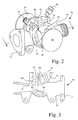
- Fig. 2
- is a perspective view of an embodiment of a venturi of the present invention, such as may be utilized with the EGR system shown in
Fig. 1 , with the cover plates removed; - Fig. 3
- is a sectional view of the venturi shown in
Fig. 2 , taken along line 3-3; - Fig. 4
- is a perspective view of another embodiment of a venturi of the present invention, with the cover plates removed;
- Fig. 5
- is a perspective view of another embodiment of a venturi of the present invention, with the cover plates installed;
- Fig. 6
- is a sectional view of the venturi shown in
Fig. 5 , taken along line 6-6; - Fig. 7
- is a sectional view of another embodiment of a venturi of the present invention;
- Fig. 8
- is a perspective view of another embodiment of a venturi of the present invention, with the cover plates removed;
- Fig. 9
- is a sectional view of the venturi shown in
Fig. 8 , taken along line 9-9; and - Figs. 10-12
- illustrate another embodiment of a venturi of the present invention.
- Referring now to the drawings, and more particularly to
Fig. 1 , there is shown an embodiment of anIC engine 10 of the present invention, which generally includes ablock 12 having a plurality ofcombustion cylinders 14,intake manifold 16,exhaust manifold 18,charge air cooler 20,turbocharger 22,EGR valve 24,EGR cooler 26 andEGR venturi 56. In the embodiment shown,IC engine 10 is a diesel engine which is incorporated into a work machine, such as an agricultural tractor or combine, but may be differently configured, depending upon the application. -
Block 12 is typically a cast metal block which is formed to definecombustion cylinders 14. In the embodiment shown,block 12 includes sixcombustion cylinders 14, but may include a different number depending upon the application.Intake manifold 16 andexhaust manifold 18 are also typically formed from cast metal, and are coupled withblock 12 in conventional manner, such as by using bolts and gaskets.Intake manifold 16 andexhaust manifold 18 are each in fluid communication withcombustion cylinders 14. Intakemanifold 16 receives charge air fromcharge air cooler 20 atintake manifold inlet 28, and supplies charge air (which may be air or a fuel/air mixture) tocombustion cylinders 14, such as by using fuel injectors (not shown). - Similarly,
exhaust manifold 18 is in fluid communication withcombustion cylinders 14, and includes anoutlet 30 from which exhaust gas fromcombustion cylinders 14 is discharged to turbocharger 22. -
Block 12 also typically includes a liquid coolant system with a number of internalliquid coolant passages 31 for coolingIC engine 10, in known manner. Only a singleliquid coolant passage 31 is shown inFig. 1 for simplicity sake.Liquid coolant passage 31 is in fluid communication withEGR venturi 56, as will be described in more detail below. -
Turbocharger 22 includes a variable geometry turbine (VGT) 32 and acompressor 34. VGT 32 is adjustably controllable as indicated byline 36, and includes an actuatable element which is controlled electronically using acontroller 37. For example, VGT 32 may be actuated by changing the position of turbine blades, a variable size orifice, or other actuatable elements. The turbine within VGT 32 is driven by exhaust gas fromexhaust manifold 18, and is exhausted to the environment, as indicated byarrow 38. - VGT 32 mechanically drives
compressor 34 through arotatable shaft 40.Compressor 34 is a fixed geometry compressor in the embodiment shown.Compressor 34 receives combustion air from the ambient environment as indicated byline 42, and discharges the compressed combustion air vialine 44 to chargeair cooler 20. As a result of the mechanical work through the compression of the combustion air, the heated charge air is cooled incharge air cooler 20 prior to being introduced atinlet 28 ofintake manifold 16. -
EGR valve 24 andEGR cooler 26 are part of anEGR system 45 which also includes afirst fluid line 46,second fluid line 48,third fluid line 50 andfourth fluid line 52. The term fluid line, as used herein, is intended broadly to cover a conduit for transporting a gas such as exhaust gas and/or combustion air, as will be understood hereinafter. - First
fluid line 46 is coupled at one end thereof with afluid line 54 interconnectingexhaust manifold outlet 30 withVGT 32. Firstfluid line 46 is coupled at an opposite end thereof withEGR cooler 26.Second fluid line 48 fluidly interconnects EGR cooler 26 withEGR valve 24.Third fluid line 50 fluidlyinterconnects EGR valve 24 withEGR venturi 56.Fourth fluid line 52 fluidlyinterconnects EGR venturi 56 withfluid line 58 extending betweencharge air cooler 20 andinlet 28 ofintake manifold 16. - The controllable components of
IC engine 10 shown inFig. 1 are generally under the control ofcontroller 37. For example,controller 37 can control operation ofVGT 32 andEGR valve 24.Controller 37 also receives signals from apressure sensor 60 associated withEGR venturi 56 as indicated byline 62, letter A. - Referring now to
Figs. 2 and 3 ,EGR venturi 56 will be described in greater detail.EGR venturi 56 includes abody 64 to which is mounted a pressure sensor 60 (shown schematically inFig. 1 , but not shown inFigs. 2 and 3 ).Body 64 defines a converginginlet section 66,throat 68 and divergingoutlet section 70.Body 64 also includes a mountingflange 72 at the inlet side of converginginlet section 66. Converginginlet section 66 is fluidly coupled with exhaust manifold 18 (by way ofEGR cooler 26 and EGR valve 24), and divergingoutlet section 70 is fluidly coupled withintake manifold 16. -
Body 64 also includes afirst sensor port 74 in communication withthroat 68, and asecond sensor port 76 in communication with converginginlet section 66. Eachsensor port surface 78 for mounting thepressure sensor 60. By sensing the differential pressure within both the converginginlet section 66 andthroat 68, the mass flow rate of the EGR gas can be determined and compared with a target EGR flow throughEGR valve 24. - According to an aspect of the present invention,
EGR venturi 56 is temperature controlled using liquid coolant associated withIC engine 10. For example, the liquid coolant can be from aliquid coolant passage 31 associated with the primary liquid coolant system (Fig. 1 ), or could be liquid coolant associated withEGR cooler 26. More particularly,EGR venturi 56 includes an interior liquidheat exchange chamber 80 adjacent tothroat 68.Heat exchange chamber 80 is in fluid communication with the liquid coolant system ofIC engine 10 viainlet port 82 andoutlet port 84.Heat exchange chamber 80 at least partially surrounds both thefirst sensor port 74 andsecond sensor port 76. In other words, both thefirst sensor port 74 andsecond sensor port 76 are essentially constructed as tubes which extend through theheat exchange chamber 80. As shown inFigs. 2 and 3 ,heat exchange chamber 80 may also at least partially surround converginginlet section 66 and/or divergingoutlet section 70. - A pair of
removable cover plates 86 are positioned on generally opposite sides ofbody 64 andcover corresponding openings 88. Eachopening 88 is in communication withheat exchange chamber 80.Cover plates 86 are structured and arranged so as to allowbody 64 to be cast as a single part casting. - From the foregoing description, it is apparent that the temperature controlled
EGR venturi 56 of the present invention uses engine coolant around thethroat 68 andpressure ports sensor 60. Water condensate (from exhaust products) in the venturi is a leading contributor for allowing soot to collect and build up on the internal geometry of the venturi. Reduction of combustion product build up is managed by maintaining a venturi wall temperature that is above the condensation point for water. By keeping water vapor from condensing to liquid on the inside of the venturi, the combustion products build up is minimized. - The coolant flow in
EGR venturi 56 also serves a second purpose - that is to regulate the temperature of thedifferential pressure sensor 60 within a given range to maintain measurement accuracy and repeatability at various ambient conditions and protect thesensor 60 from overheating. -
Fig. 4 illustrates another embodiment of anEGR venturi 90 of the present invention.EGR venturi 90 again includes a pair of tube shapedsensor ports 92, aliquid coolant chamber 94 surrounding a portion of the inlet section, throat and outlet section, and a pair ofopposite openings 96 to which attach removable cover plates (not shown). - Three other embodiments of EGR venturis 100, 102 and 104 are shown in
Figs. 5-6 ,7 and8-9 , respectively. The features of these EGR venturi embodiments are believed to be self evident from the foregoing detailed description of the present invention, and therefore will not be described in greater detail herein. - A further embodiment of an
EGR venturi 106 is shown inFigs. 10-12 .EGR venturi 106 has a multi-part body with a wedge shapedbody portion 108 to which is mounted thesensor assembly 110. Wedge shapedbody portion 108 defines the interior liquidheat exchange chamber 112 for coolingEGR venturi 106. The features ofEGR venturi 106 are otherwise similar to the embodiments described above, and therefore will not be described in greater detail herein. - In summary, the temperature controlled EGR venturi of the present invention includes a venturi with a coolant manifold integrated around the exterior of the gas passages and two cover plates to seal coolant inside the manifold. Two ports for coolant input and output allow the fluid to flow through the manifold. The coolant transfers heat to the venturi via this manifold. The design of the present invention gives perfomance advantages over typical venturi designs because of temperature control of the inside walls to prevent condensation/soot build-up, temperature control of the pressure sensor to improve accuracy/repeatability, and direct sensor mounting to the venturi. The production intent design using removable cover plates provides a manufacturing advantage because the casting does not require a core and it allows for reduction in precious metal but still allows good surface area for coolant to venturi heat transfer around pressure ports and the throat.
- Having described the preferred embodiment, it will become apparent that various modifications can be made without departing from the scope of the invention as defined in the accompanying claims.
Claims (13)
- An exhaust gas recirculation (EGR) venturi (56) for use in an EGR system of an internal combustion (IC) engine (10), said EGR venture (56) comprising a body (64) defining a converging inlet section (66), a throat (68), and an interior liquid heat exchange chamber (80) adjacent said throat (68).
- The EGR venturi according to claim 1, characterized in that said body (64) includes a first sensor port (74) in communication with said throat (68).
- The EGR venturi according to claim 1 or 2, characterized in that said first sensor port (74) is substantially surrounded by said heat exchange chamber (80).
- The EGR venturi according to one or several of the previous claims, characterized in that said body includes a second sensor port (74) in communication with said converging inlet section (66).
- The EGR venturi according to claim 4, characterized in that said second sensor port (74) is substantially surrounded by said heat exchange chamber (80).
- The EGR venturi according to one or several of the previous claims, characterized by at least one removable cover plate (86), each said cover plate (86) covering a corresponding opening (88) in said body (64) which is in communication with said heat exchange chamber (80).
- The EGR venturi according to one or several of the previous claims, characterized in that said at least one removable cover plate (86) comprises a pair of cover plates (86) which respectively cover a corresponding pair of said openings (88) on generally opposite sides of said body (64).
- The EGR venturi according to claim 7, characterized in that said pair of cover plates (88) are structured and arranged so as to allow said body (64) to be cast as a single part casting.
- The EGR venturi according to one or several of the previous claims, characterized in that said heat exchange chamber (80) is adjacent at least a portion of said converging inlet section (66).
- The EGR venturi according to one or several of the previous claims, characterized in that said body (64) includes a diverging outlet section, and wherein said heat exchange chamber (80) is adjacent at least a portion of said diverging outlet section (70).
- The EGR venturi according to one or several of the previous claims, characterized in that said body includes an inlet port (82) and an outlet port (84) in communication with said heat exchange chamber (80).
- An internal combustion (IC) engine (10), comprising a block (12) defining at least one combustion cylinder (14) and a liquid coolant system; an intake manifold (16) fluidly coupled with at least one said combustion cylinder (14); an exhaust manifold (18) fluidly coupled with at least one said combustion cylinder (14); characterized by an EGR venturi (56) fluidly coupled between said exhaust manifold (18) and said intake manifold (16), wherein said the inlet section (66) of said EGR venturi (56) is fluidly coupled with said exhaust manifold (28), and said heat exchange chamber (60) being in fluid communication with said liquid coolant system.
- An exhaust gas recirculation (EGR) system for an internal combustion engine (IC) (10), the internal combustion engine (10) including an intake manifold (16), an exhaust manifold (18), and a liquid coolant system, said EGR system comprising an EGR venture (56) according to one or several of the claims 1 to 11, wherein the inlet section (66) of said EGR venturi (56) is fluidly coupled with said exhaust manifold (18) and, said heat exchange chamber (60) being in fluid communication with said liquid coolant system.
Applications Claiming Priority (1)
| Application Number | Priority Date | Filing Date | Title |
|---|---|---|---|
| US12/342,674 US7921830B2 (en) | 2008-12-23 | 2008-12-23 | Temperature controlled venturi for use with an EGR system in an internal combustion engine |
Publications (3)
| Publication Number | Publication Date |
|---|---|
| EP2202402A2 true EP2202402A2 (en) | 2010-06-30 |
| EP2202402A3 EP2202402A3 (en) | 2013-04-10 |
| EP2202402B1 EP2202402B1 (en) | 2015-07-29 |
Family
ID=41491526
Family Applications (1)
| Application Number | Title | Priority Date | Filing Date |
|---|---|---|---|
| EP09178289.6A Active EP2202402B1 (en) | 2008-12-23 | 2009-12-08 | Temperature controlled venturi for use with an EGR system in an internal combustion engine |
Country Status (4)
| Country | Link |
|---|---|
| US (1) | US7921830B2 (en) |
| EP (1) | EP2202402B1 (en) |
| CN (1) | CN101761421A (en) |
| BR (1) | BRPI0905187A2 (en) |
Cited By (3)
| Publication number | Priority date | Publication date | Assignee | Title |
|---|---|---|---|---|
| WO2014027997A1 (en) | 2012-08-14 | 2014-02-20 | Mack Trucks, Inc. | Vacuum insulated venturi meter for an exhaust gas recirculation apparatus |
| US9695785B2 (en) | 2013-11-11 | 2017-07-04 | Borgwarner Inc. | Turbocharger with integrated venturi mixer and EGR valve system |
| US9816466B2 (en) | 2013-11-11 | 2017-11-14 | Borgwarner Inc. | Condensing EGR-mixer system |
Families Citing this family (15)
| Publication number | Priority date | Publication date | Assignee | Title |
|---|---|---|---|---|
| CN102797595A (en) * | 2011-05-25 | 2012-11-28 | 广西玉柴机器股份有限公司 | Exhaust gas recirculation (EGR) system for diesel engine |
| US20130133631A1 (en) * | 2011-11-30 | 2013-05-30 | Caterpillar Inc. | System to measure parameters of a particulate laden flow |
| US8938961B2 (en) * | 2011-12-30 | 2015-01-27 | Caterpillar Inc. | EGR flow sensor for an engine |
| US9151250B2 (en) * | 2012-04-05 | 2015-10-06 | Donald B. Scoggins | Fluid cooling system |
| US20130298882A1 (en) * | 2012-05-14 | 2013-11-14 | Caterpillar, Inc. | EGR with Temperature Controlled Venturi Flow Meter |
| US20140174078A1 (en) * | 2012-12-20 | 2014-06-26 | Caterpillar Inc. | Egr system having flow restricting valve |
| US9163586B2 (en) * | 2013-01-31 | 2015-10-20 | Electro-Motive Diesel, Inc. | Exhaust system having parallel EGR coolers |
| US20140261349A1 (en) * | 2013-03-13 | 2014-09-18 | Caterpillar Inc. | System and method for sensor cooling |
| US9291097B2 (en) | 2013-06-04 | 2016-03-22 | Caterpillar Inc. | Cooling module for electronic engine components |
| US10012123B2 (en) * | 2014-04-04 | 2018-07-03 | Nissan Motor Co., Ltd. | Exhaust device of engine |
| GB2549286B (en) * | 2016-04-11 | 2019-07-24 | Perkins Engines Co Ltd | EGR valve with integrated sensor |
| CN109790801A (en) * | 2016-09-19 | 2019-05-21 | 康明斯有限公司 | The cast type EGR cross pipe with integral venturi for flow measurement |
| DE102017000699A1 (en) * | 2017-01-26 | 2018-07-26 | Man Truck & Bus Ag | Device for attaching a control device to an internal combustion engine |
| KR102463205B1 (en) * | 2017-12-20 | 2022-11-03 | 현대자동차 주식회사 | Egr cooler for vehicle |
| CN110748443A (en) * | 2019-11-26 | 2020-02-04 | 广西玉柴机器股份有限公司 | An exhaust gas recirculation system |
Citations (1)
| Publication number | Priority date | Publication date | Assignee | Title |
|---|---|---|---|---|
| US20080141757A1 (en) | 2006-12-15 | 2008-06-19 | Caterpillar Inc. | Onboard method of determining EGR flow rate |
Family Cites Families (20)
| Publication number | Priority date | Publication date | Assignee | Title |
|---|---|---|---|---|
| US2354151A (en) * | 1942-04-16 | 1944-07-18 | United Aircraft Corp | Fluid nozzle |
| US3188801A (en) * | 1961-09-29 | 1965-06-15 | Gen Motors Corp | Cooled nozzle construction |
| US4426848A (en) * | 1981-11-20 | 1984-01-24 | Dresser Industries, Inc. | Turbocharged engine exhaust gas recirculation system |
| US4671060A (en) | 1984-03-07 | 1987-06-09 | Wilkens Robert G | Explosion-protected diesel engine |
| US5331930A (en) * | 1993-04-05 | 1994-07-26 | Mcwhorter Edward M | Univalve engine |
| JP3560658B2 (en) * | 1994-11-09 | 2004-09-02 | ヤマハマリン株式会社 | Engine air-fuel ratio detector |
| US5857838A (en) * | 1997-04-09 | 1999-01-12 | Lockheed Martin Idaho Technologies Company | Water cooled steam jet |
| US6351946B1 (en) | 1999-09-27 | 2002-03-05 | Caterpillar Inc. | Exhaust gas recirculation system in an internal combustion engine |
| US6301887B1 (en) | 2000-05-26 | 2001-10-16 | Engelhard Corporation | Low pressure EGR system for diesel engines |
| US6786210B2 (en) * | 2002-06-21 | 2004-09-07 | Detroit Diesel Corporation | Working fluid circuit for a turbocharged engine having exhaust gas recirculation |
| US6742335B2 (en) * | 2002-07-11 | 2004-06-01 | Clean Air Power, Inc. | EGR control system and method for an internal combustion engine |
| DE10232515A1 (en) | 2002-07-18 | 2004-04-08 | Daimlerchrysler Ag | Exhaust gas recirculation of an internal combustion engine |
| US6978772B1 (en) | 2003-02-03 | 2005-12-27 | Chapeau, Inc. | EGR cooling and condensate regulation system for natural gas fired co-generation unit |
| GB2416385B (en) * | 2004-03-16 | 2006-04-12 | Tour & Andersson Ab | Valve assembly |
| GB2416565B (en) | 2004-07-23 | 2008-02-13 | Visteon Global Tech Inc | Pressure boosted IC engine with exhaust gas recirculation |
| TWI247136B (en) | 2004-09-17 | 2006-01-11 | Ind Tech Res Inst | Optical device and method of making the same |
| JP2006118495A (en) * | 2004-09-22 | 2006-05-11 | Toyota Motor Corp | Intake negative pressure booster for internal combustion engine |
| US7380544B2 (en) | 2006-05-19 | 2008-06-03 | Modine Manufacturing Company | EGR cooler with dual coolant loop |
| US7451750B1 (en) * | 2007-06-29 | 2008-11-18 | Caterpillar Inc. | Condensation reduction device for an EGR equipped system |
| US20090084193A1 (en) * | 2007-09-27 | 2009-04-02 | Victor Cerabone | Apparatus for measuring an exhaust gas recirculation flow of an internal combustion engine |
-
2008
- 2008-12-23 US US12/342,674 patent/US7921830B2/en active Active
-
2009
- 2009-11-10 CN CN200910210574A patent/CN101761421A/en active Pending
- 2009-12-08 EP EP09178289.6A patent/EP2202402B1/en active Active
- 2009-12-21 BR BRPI0905187-2A patent/BRPI0905187A2/en not_active IP Right Cessation
Patent Citations (1)
| Publication number | Priority date | Publication date | Assignee | Title |
|---|---|---|---|---|
| US20080141757A1 (en) | 2006-12-15 | 2008-06-19 | Caterpillar Inc. | Onboard method of determining EGR flow rate |
Cited By (4)
| Publication number | Priority date | Publication date | Assignee | Title |
|---|---|---|---|---|
| WO2014027997A1 (en) | 2012-08-14 | 2014-02-20 | Mack Trucks, Inc. | Vacuum insulated venturi meter for an exhaust gas recirculation apparatus |
| EP2885523A4 (en) * | 2012-08-14 | 2016-05-25 | Mack Trucks | Vacuum insulated venturi meter for an exhaust gas recirculation apparatus |
| US9695785B2 (en) | 2013-11-11 | 2017-07-04 | Borgwarner Inc. | Turbocharger with integrated venturi mixer and EGR valve system |
| US9816466B2 (en) | 2013-11-11 | 2017-11-14 | Borgwarner Inc. | Condensing EGR-mixer system |
Also Published As
| Publication number | Publication date |
|---|---|
| US20100154758A1 (en) | 2010-06-24 |
| EP2202402A3 (en) | 2013-04-10 |
| US7921830B2 (en) | 2011-04-12 |
| CN101761421A (en) | 2010-06-30 |
| EP2202402B1 (en) | 2015-07-29 |
| BRPI0905187A2 (en) | 2011-02-15 |
Similar Documents
| Publication | Publication Date | Title |
|---|---|---|
| EP2202402B1 (en) | Temperature controlled venturi for use with an EGR system in an internal combustion engine | |
| US6138650A (en) | Method of controlling fuel injectors for improved exhaust gas recirculation | |
| US7444815B2 (en) | EGR system for high EGR rates | |
| US8439021B2 (en) | EGR system for an internal combustion engine | |
| US20070144170A1 (en) | Compressor having integral EGR valve and mixer | |
| US8261724B2 (en) | Intake apparatus for internal combustion engine | |
| US8938961B2 (en) | EGR flow sensor for an engine | |
| US20070074512A1 (en) | Turbocharged internal combustion engine with EGR system having reverse flow | |
| US20130298882A1 (en) | EGR with Temperature Controlled Venturi Flow Meter | |
| US7363919B1 (en) | Integrated exhaust gas recirculation valve and cooler system | |
| EP3438433B1 (en) | Engine device | |
| US8534239B2 (en) | Multi-cylinder diesel engine | |
| US7841323B2 (en) | Internal-combustion engine having a cooled exhaust gas recirculation system as well as an exhaust gas manifold | |
| GB2418012A (en) | Working fluid circuit for a turbocharged engine having exhaust gas recirculation | |
| US6598396B2 (en) | Internal combustion engine EGR system utilizing stationary regenerators in a piston pumped boost cooled arrangement | |
| US6062027A (en) | Internal combustion engine with an exhaust gas turbocharger | |
| CN101182821A (en) | Exhaust gas recirculation system for an internal combustion engine | |
| CN101187346A (en) | Exhaust gas recirculation system for an internal combustion engine | |
| EP1939439B1 (en) | Engine with internal EGR system | |
| US9394862B2 (en) | Interface part between a motor vehicle engine head and a heat exchanger | |
| US20100145598A1 (en) | Apparatus for measuring egr and method | |
| JP5089603B2 (en) | Exhaust gas recirculation mixer for internal combustion engine with turbocharge | |
| US7343908B2 (en) | EGR system having EGR valve with purge air chamber | |
| CN110219754B (en) | exhaust gas recirculation system | |
| US11261767B2 (en) | Bifurcated air induction system for turbocharged engines |
Legal Events
| Date | Code | Title | Description |
|---|---|---|---|
| PUAI | Public reference made under article 153(3) epc to a published international application that has entered the european phase |
Free format text: ORIGINAL CODE: 0009012 |
|
| AK | Designated contracting states |
Kind code of ref document: A2 Designated state(s): AT BE BG CH CY CZ DE DK EE ES FI FR GB GR HR HU IE IS IT LI LT LU LV MC MK MT NL NO PL PT RO SE SI SK SM TR |
|
| PUAL | Search report despatched |
Free format text: ORIGINAL CODE: 0009013 |
|
| AK | Designated contracting states |
Kind code of ref document: A3 Designated state(s): AT BE BG CH CY CZ DE DK EE ES FI FR GB GR HR HU IE IS IT LI LT LU LV MC MK MT NL NO PL PT RO SE SI SK SM TR |
|
| RIC1 | Information provided on ipc code assigned before grant |
Ipc: G01F 1/44 20060101ALI20130307BHEP Ipc: F02M 25/07 20060101AFI20130307BHEP |
|
| 17P | Request for examination filed |
Effective date: 20131010 |
|
| RBV | Designated contracting states (corrected) |
Designated state(s): AT BE BG CH CY CZ DE DK EE ES FI FR GB GR HR HU IE IS IT LI LT LU LV MC MK MT NL NO PL PT RO SE SI SK SM TR |
|
| REG | Reference to a national code |
Ref country code: DE Ref legal event code: R079 Ref document number: 602009032453 Country of ref document: DE Free format text: PREVIOUS MAIN CLASS: F02M0025070000 Ipc: G01F0015140000 |
|
| GRAP | Despatch of communication of intention to grant a patent |
Free format text: ORIGINAL CODE: EPIDOSNIGR1 |
|
| RIC1 | Information provided on ipc code assigned before grant |
Ipc: F02M 25/07 20060101ALI20150127BHEP Ipc: G01F 1/44 20060101ALI20150127BHEP Ipc: G01F 15/14 20060101AFI20150127BHEP |
|
| INTG | Intention to grant announced |
Effective date: 20150225 |
|
| GRAS | Grant fee paid |
Free format text: ORIGINAL CODE: EPIDOSNIGR3 |
|
| GRAA | (expected) grant |
Free format text: ORIGINAL CODE: 0009210 |
|
| AK | Designated contracting states |
Kind code of ref document: B1 Designated state(s): AT BE BG CH CY CZ DE DK EE ES FI FR GB GR HR HU IE IS IT LI LT LU LV MC MK MT NL NO PL PT RO SE SI SK SM TR |
|
| REG | Reference to a national code |
Ref country code: GB Ref legal event code: FG4D |
|
| REG | Reference to a national code |
Ref country code: CH Ref legal event code: EP |
|
| REG | Reference to a national code |
Ref country code: AT Ref legal event code: REF Ref document number: 739676 Country of ref document: AT Kind code of ref document: T Effective date: 20150815 |
|
| REG | Reference to a national code |
Ref country code: IE Ref legal event code: FG4D |
|
| REG | Reference to a national code |
Ref country code: DE Ref legal event code: R096 Ref document number: 602009032453 Country of ref document: DE |
|
| REG | Reference to a national code |
Ref country code: AT Ref legal event code: MK05 Ref document number: 739676 Country of ref document: AT Kind code of ref document: T Effective date: 20150729 |
|
| REG | Reference to a national code |
Ref country code: LT Ref legal event code: MG4D |
|
| REG | Reference to a national code |
Ref country code: NL Ref legal event code: MP Effective date: 20150729 |
|
| PG25 | Lapsed in a contracting state [announced via postgrant information from national office to epo] |
Ref country code: LT Free format text: LAPSE BECAUSE OF FAILURE TO SUBMIT A TRANSLATION OF THE DESCRIPTION OR TO PAY THE FEE WITHIN THE PRESCRIBED TIME-LIMIT Effective date: 20150729 Ref country code: LV Free format text: LAPSE BECAUSE OF FAILURE TO SUBMIT A TRANSLATION OF THE DESCRIPTION OR TO PAY THE FEE WITHIN THE PRESCRIBED TIME-LIMIT Effective date: 20150729 Ref country code: NO Free format text: LAPSE BECAUSE OF FAILURE TO SUBMIT A TRANSLATION OF THE DESCRIPTION OR TO PAY THE FEE WITHIN THE PRESCRIBED TIME-LIMIT Effective date: 20151029 Ref country code: FI Free format text: LAPSE BECAUSE OF FAILURE TO SUBMIT A TRANSLATION OF THE DESCRIPTION OR TO PAY THE FEE WITHIN THE PRESCRIBED TIME-LIMIT Effective date: 20150729 Ref country code: GR Free format text: LAPSE BECAUSE OF FAILURE TO SUBMIT A TRANSLATION OF THE DESCRIPTION OR TO PAY THE FEE WITHIN THE PRESCRIBED TIME-LIMIT Effective date: 20151030 |
|
| PG25 | Lapsed in a contracting state [announced via postgrant information from national office to epo] |
Ref country code: ES Free format text: LAPSE BECAUSE OF FAILURE TO SUBMIT A TRANSLATION OF THE DESCRIPTION OR TO PAY THE FEE WITHIN THE PRESCRIBED TIME-LIMIT Effective date: 20150729 Ref country code: PT Free format text: LAPSE BECAUSE OF FAILURE TO SUBMIT A TRANSLATION OF THE DESCRIPTION OR TO PAY THE FEE WITHIN THE PRESCRIBED TIME-LIMIT Effective date: 20151130 Ref country code: PL Free format text: LAPSE BECAUSE OF FAILURE TO SUBMIT A TRANSLATION OF THE DESCRIPTION OR TO PAY THE FEE WITHIN THE PRESCRIBED TIME-LIMIT Effective date: 20150729 Ref country code: HR Free format text: LAPSE BECAUSE OF FAILURE TO SUBMIT A TRANSLATION OF THE DESCRIPTION OR TO PAY THE FEE WITHIN THE PRESCRIBED TIME-LIMIT Effective date: 20150729 Ref country code: AT Free format text: LAPSE BECAUSE OF FAILURE TO SUBMIT A TRANSLATION OF THE DESCRIPTION OR TO PAY THE FEE WITHIN THE PRESCRIBED TIME-LIMIT Effective date: 20150729 Ref country code: IS Free format text: LAPSE BECAUSE OF FAILURE TO SUBMIT A TRANSLATION OF THE DESCRIPTION OR TO PAY THE FEE WITHIN THE PRESCRIBED TIME-LIMIT Effective date: 20151129 Ref country code: SE Free format text: LAPSE BECAUSE OF FAILURE TO SUBMIT A TRANSLATION OF THE DESCRIPTION OR TO PAY THE FEE WITHIN THE PRESCRIBED TIME-LIMIT Effective date: 20150729 |
|
| PG25 | Lapsed in a contracting state [announced via postgrant information from national office to epo] |
Ref country code: NL Free format text: LAPSE BECAUSE OF FAILURE TO SUBMIT A TRANSLATION OF THE DESCRIPTION OR TO PAY THE FEE WITHIN THE PRESCRIBED TIME-LIMIT Effective date: 20150729 |
|
| PG25 | Lapsed in a contracting state [announced via postgrant information from national office to epo] |
Ref country code: DK Free format text: LAPSE BECAUSE OF FAILURE TO SUBMIT A TRANSLATION OF THE DESCRIPTION OR TO PAY THE FEE WITHIN THE PRESCRIBED TIME-LIMIT Effective date: 20150729 Ref country code: EE Free format text: LAPSE BECAUSE OF FAILURE TO SUBMIT A TRANSLATION OF THE DESCRIPTION OR TO PAY THE FEE WITHIN THE PRESCRIBED TIME-LIMIT Effective date: 20150729 Ref country code: IT Free format text: LAPSE BECAUSE OF FAILURE TO SUBMIT A TRANSLATION OF THE DESCRIPTION OR TO PAY THE FEE WITHIN THE PRESCRIBED TIME-LIMIT Effective date: 20150729 Ref country code: SK Free format text: LAPSE BECAUSE OF FAILURE TO SUBMIT A TRANSLATION OF THE DESCRIPTION OR TO PAY THE FEE WITHIN THE PRESCRIBED TIME-LIMIT Effective date: 20150729 Ref country code: CZ Free format text: LAPSE BECAUSE OF FAILURE TO SUBMIT A TRANSLATION OF THE DESCRIPTION OR TO PAY THE FEE WITHIN THE PRESCRIBED TIME-LIMIT Effective date: 20150729 |
|
| REG | Reference to a national code |
Ref country code: DE Ref legal event code: R097 Ref document number: 602009032453 Country of ref document: DE |
|
| PG25 | Lapsed in a contracting state [announced via postgrant information from national office to epo] |
Ref country code: BE Free format text: LAPSE BECAUSE OF NON-PAYMENT OF DUE FEES Effective date: 20151231 Ref country code: RO Free format text: LAPSE BECAUSE OF FAILURE TO SUBMIT A TRANSLATION OF THE DESCRIPTION OR TO PAY THE FEE WITHIN THE PRESCRIBED TIME-LIMIT Effective date: 20150729 |
|
| PLBE | No opposition filed within time limit |
Free format text: ORIGINAL CODE: 0009261 |
|
| STAA | Information on the status of an ep patent application or granted ep patent |
Free format text: STATUS: NO OPPOSITION FILED WITHIN TIME LIMIT |
|
| 26N | No opposition filed |
Effective date: 20160502 |
|
| PG25 | Lapsed in a contracting state [announced via postgrant information from national office to epo] |
Ref country code: LU Free format text: LAPSE BECAUSE OF FAILURE TO SUBMIT A TRANSLATION OF THE DESCRIPTION OR TO PAY THE FEE WITHIN THE PRESCRIBED TIME-LIMIT Effective date: 20151208 Ref country code: MC Free format text: LAPSE BECAUSE OF FAILURE TO SUBMIT A TRANSLATION OF THE DESCRIPTION OR TO PAY THE FEE WITHIN THE PRESCRIBED TIME-LIMIT Effective date: 20150729 |
|
| REG | Reference to a national code |
Ref country code: CH Ref legal event code: PL |
|
| PG25 | Lapsed in a contracting state [announced via postgrant information from national office to epo] |
Ref country code: SI Free format text: LAPSE BECAUSE OF FAILURE TO SUBMIT A TRANSLATION OF THE DESCRIPTION OR TO PAY THE FEE WITHIN THE PRESCRIBED TIME-LIMIT Effective date: 20150729 |
|
| REG | Reference to a national code |
Ref country code: IE Ref legal event code: MM4A |
|
| REG | Reference to a national code |
Ref country code: FR Ref legal event code: ST Effective date: 20160831 |
|
| PG25 | Lapsed in a contracting state [announced via postgrant information from national office to epo] |
Ref country code: IE Free format text: LAPSE BECAUSE OF NON-PAYMENT OF DUE FEES Effective date: 20151208 Ref country code: CH Free format text: LAPSE BECAUSE OF NON-PAYMENT OF DUE FEES Effective date: 20151231 Ref country code: LI Free format text: LAPSE BECAUSE OF NON-PAYMENT OF DUE FEES Effective date: 20151231 |
|
| PG25 | Lapsed in a contracting state [announced via postgrant information from national office to epo] |
Ref country code: FR Free format text: LAPSE BECAUSE OF NON-PAYMENT OF DUE FEES Effective date: 20151231 |
|
| PG25 | Lapsed in a contracting state [announced via postgrant information from national office to epo] |
Ref country code: BE Free format text: LAPSE BECAUSE OF FAILURE TO SUBMIT A TRANSLATION OF THE DESCRIPTION OR TO PAY THE FEE WITHIN THE PRESCRIBED TIME-LIMIT Effective date: 20150729 |
|
| PG25 | Lapsed in a contracting state [announced via postgrant information from national office to epo] |
Ref country code: BG Free format text: LAPSE BECAUSE OF FAILURE TO SUBMIT A TRANSLATION OF THE DESCRIPTION OR TO PAY THE FEE WITHIN THE PRESCRIBED TIME-LIMIT Effective date: 20150729 Ref country code: HU Free format text: LAPSE BECAUSE OF FAILURE TO SUBMIT A TRANSLATION OF THE DESCRIPTION OR TO PAY THE FEE WITHIN THE PRESCRIBED TIME-LIMIT; INVALID AB INITIO Effective date: 20091208 Ref country code: SM Free format text: LAPSE BECAUSE OF FAILURE TO SUBMIT A TRANSLATION OF THE DESCRIPTION OR TO PAY THE FEE WITHIN THE PRESCRIBED TIME-LIMIT Effective date: 20150729 |
|
| PG25 | Lapsed in a contracting state [announced via postgrant information from national office to epo] |
Ref country code: CY Free format text: LAPSE BECAUSE OF FAILURE TO SUBMIT A TRANSLATION OF THE DESCRIPTION OR TO PAY THE FEE WITHIN THE PRESCRIBED TIME-LIMIT Effective date: 20150729 |
|
| PG25 | Lapsed in a contracting state [announced via postgrant information from national office to epo] |
Ref country code: MT Free format text: LAPSE BECAUSE OF FAILURE TO SUBMIT A TRANSLATION OF THE DESCRIPTION OR TO PAY THE FEE WITHIN THE PRESCRIBED TIME-LIMIT Effective date: 20150729 Ref country code: TR Free format text: LAPSE BECAUSE OF FAILURE TO SUBMIT A TRANSLATION OF THE DESCRIPTION OR TO PAY THE FEE WITHIN THE PRESCRIBED TIME-LIMIT Effective date: 20150729 |
|
| PG25 | Lapsed in a contracting state [announced via postgrant information from national office to epo] |
Ref country code: MK Free format text: LAPSE BECAUSE OF FAILURE TO SUBMIT A TRANSLATION OF THE DESCRIPTION OR TO PAY THE FEE WITHIN THE PRESCRIBED TIME-LIMIT Effective date: 20150729 |
|
| PGFP | Annual fee paid to national office [announced via postgrant information from national office to epo] |
Ref country code: DE Payment date: 20251119 Year of fee payment: 17 |
|
| PGFP | Annual fee paid to national office [announced via postgrant information from national office to epo] |
Ref country code: GB Payment date: 20251229 Year of fee payment: 17 |