EP2202264A1 - Procédé de fabrication par moulage d'un élément structurel de machine avec une surface abradable et élément structurel - Google Patents
Procédé de fabrication par moulage d'un élément structurel de machine avec une surface abradable et élément structurel Download PDFInfo
- Publication number
- EP2202264A1 EP2202264A1 EP08172881A EP08172881A EP2202264A1 EP 2202264 A1 EP2202264 A1 EP 2202264A1 EP 08172881 A EP08172881 A EP 08172881A EP 08172881 A EP08172881 A EP 08172881A EP 2202264 A1 EP2202264 A1 EP 2202264A1
- Authority
- EP
- European Patent Office
- Prior art keywords
- filler material
- manufacturing
- structural element
- fibers
- heat treatment
- Prior art date
- Legal status (The legal status is an assumption and is not a legal conclusion. Google has not performed a legal analysis and makes no representation as to the accuracy of the status listed.)
- Granted
Links
Images
Classifications
-
- B—PERFORMING OPERATIONS; TRANSPORTING
- B29—WORKING OF PLASTICS; WORKING OF SUBSTANCES IN A PLASTIC STATE IN GENERAL
- B29C—SHAPING OR JOINING OF PLASTICS; SHAPING OF MATERIAL IN A PLASTIC STATE, NOT OTHERWISE PROVIDED FOR; AFTER-TREATMENT OF THE SHAPED PRODUCTS, e.g. REPAIRING
- B29C44/00—Shaping by internal pressure generated in the material, e.g. swelling or foaming ; Producing porous or cellular expanded plastics articles
- B29C44/02—Shaping by internal pressure generated in the material, e.g. swelling or foaming ; Producing porous or cellular expanded plastics articles for articles of definite length, i.e. discrete articles
- B29C44/04—Shaping by internal pressure generated in the material, e.g. swelling or foaming ; Producing porous or cellular expanded plastics articles for articles of definite length, i.e. discrete articles consisting of at least two parts of chemically or physically different materials, e.g. having different densities
- B29C44/06—Making multilayered articles
- B29C44/065—Making multilayered articles comprising at least one barrier layer
-
- B—PERFORMING OPERATIONS; TRANSPORTING
- B29—WORKING OF PLASTICS; WORKING OF SUBSTANCES IN A PLASTIC STATE IN GENERAL
- B29C—SHAPING OR JOINING OF PLASTICS; SHAPING OF MATERIAL IN A PLASTIC STATE, NOT OTHERWISE PROVIDED FOR; AFTER-TREATMENT OF THE SHAPED PRODUCTS, e.g. REPAIRING
- B29C44/00—Shaping by internal pressure generated in the material, e.g. swelling or foaming ; Producing porous or cellular expanded plastics articles
- B29C44/34—Auxiliary operations
- B29C44/56—After-treatment of articles, e.g. for altering the shape
- B29C44/5627—After-treatment of articles, e.g. for altering the shape by mechanical deformation, e.g. crushing, embossing, stretching
- B29C44/5636—After-treatment of articles, e.g. for altering the shape by mechanical deformation, e.g. crushing, embossing, stretching with the addition of heat
-
- F—MECHANICAL ENGINEERING; LIGHTING; HEATING; WEAPONS; BLASTING
- F01—MACHINES OR ENGINES IN GENERAL; ENGINE PLANTS IN GENERAL; STEAM ENGINES
- F01D—NON-POSITIVE DISPLACEMENT MACHINES OR ENGINES, e.g. STEAM TURBINES
- F01D5/00—Blades; Blade-carrying members; Heating, heat-insulating, cooling or antivibration means on the blades or the members
- F01D5/005—Repairing methods or devices
-
- F—MECHANICAL ENGINEERING; LIGHTING; HEATING; WEAPONS; BLASTING
- F01—MACHINES OR ENGINES IN GENERAL; ENGINE PLANTS IN GENERAL; STEAM ENGINES
- F01D—NON-POSITIVE DISPLACEMENT MACHINES OR ENGINES, e.g. STEAM TURBINES
- F01D9/00—Stators
- F01D9/02—Nozzles; Nozzle boxes; Stator blades; Guide conduits, e.g. individual nozzles
- F01D9/04—Nozzles; Nozzle boxes; Stator blades; Guide conduits, e.g. individual nozzles forming ring or sector
-
- F—MECHANICAL ENGINEERING; LIGHTING; HEATING; WEAPONS; BLASTING
- F05—INDEXING SCHEMES RELATING TO ENGINES OR PUMPS IN VARIOUS SUBCLASSES OF CLASSES F01-F04
- F05C—INDEXING SCHEME RELATING TO MATERIALS, MATERIAL PROPERTIES OR MATERIAL CHARACTERISTICS FOR MACHINES, ENGINES OR PUMPS OTHER THAN NON-POSITIVE-DISPLACEMENT MACHINES OR ENGINES
- F05C2225/00—Synthetic polymers, e.g. plastics; Rubber
- F05C2225/08—Thermoplastics
-
- F—MECHANICAL ENGINEERING; LIGHTING; HEATING; WEAPONS; BLASTING
- F05—INDEXING SCHEMES RELATING TO ENGINES OR PUMPS IN VARIOUS SUBCLASSES OF CLASSES F01-F04
- F05D—INDEXING SCHEME FOR ASPECTS RELATING TO NON-POSITIVE-DISPLACEMENT MACHINES OR ENGINES, GAS-TURBINES OR JET-PROPULSION PLANTS
- F05D2230/00—Manufacture
- F05D2230/20—Manufacture essentially without removing material
- F05D2230/21—Manufacture essentially without removing material by casting
-
- F—MECHANICAL ENGINEERING; LIGHTING; HEATING; WEAPONS; BLASTING
- F05—INDEXING SCHEMES RELATING TO ENGINES OR PUMPS IN VARIOUS SUBCLASSES OF CLASSES F01-F04
- F05D—INDEXING SCHEME FOR ASPECTS RELATING TO NON-POSITIVE-DISPLACEMENT MACHINES OR ENGINES, GAS-TURBINES OR JET-PROPULSION PLANTS
- F05D2300/00—Materials; Properties thereof
- F05D2300/20—Oxide or non-oxide ceramics
- F05D2300/22—Non-oxide ceramics
- F05D2300/224—Carbon, e.g. graphite
-
- F—MECHANICAL ENGINEERING; LIGHTING; HEATING; WEAPONS; BLASTING
- F05—INDEXING SCHEMES RELATING TO ENGINES OR PUMPS IN VARIOUS SUBCLASSES OF CLASSES F01-F04
- F05D—INDEXING SCHEME FOR ASPECTS RELATING TO NON-POSITIVE-DISPLACEMENT MACHINES OR ENGINES, GAS-TURBINES OR JET-PROPULSION PLANTS
- F05D2300/00—Materials; Properties thereof
- F05D2300/60—Properties or characteristics given to material by treatment or manufacturing
- F05D2300/614—Fibres or filaments
Definitions
- the invention relates to a method of manufacturing a structural element made of composite material with a friction surface, more particularly to a process for manufacturing by molding a structural element such as a ferrule of an axial turbomachine compressor. .
- the invention also relates to a structural element such as a shell of an axial turbomachine compressor.
- the document EP 0 219 445 discloses an inner ring of a rectifying grid of a compressor of an axial turbine.
- the inner ferrule is made of composite material and consists of an internal ring made of laminated structure comprising layers of Kevlar® polyamide fibers embedded in an epoxy resin.
- the ferrule also comprises a series of embossed sections intended to be glued to the inner ring and to receive the blade roots. These sections are also made of composite material consisting of glass fibers embedded in a resin.
- a joint cooperating with two ribs of the rotor is attached to the inner surface of the inner ring. This joint forms with the two ribs a labyrinth seal.
- the construction of the composite inner shell of this document is complex because it requires the manufacture and assembly of several elements constituting it.
- the teaching of this document is also limited to an internal ferrule.
- the document US 4,135,851 discloses an abradable liner of an outer ring of compressor or axial turbine.
- the liner is ring-shaped to be inserted and then fixed, for example by gluing, to the ferrule probably metallic.
- the liner is formed of a ring-shaped carrier comprising corrugated metal sheets and a layer of abradable material attached to the inner surface of the carrier.
- the support in corrugated metal sheets makes it possible to resume some deformations of the abradable layer, thus avoiding possible damage to the rotor blade heads and / or ferrule during contact between these two elements during operation of the machine.
- This type of construction is also quite complex because involving the realization of several elements and their assembly.
- WO 2005/014979 discloses a method for applying mud-like metallic material to a surface by dipping, brushing, spraying, or vapor deposition and controlling its porosity during firing.
- the applied material comprises plastic microbeads.
- the applied layer becomes porous during vaporization cooking of the microbeads. This method is, however, limited to the formation of an abradable layer on a metal ferrule.
- the teachings detailed above fail to provide a simple solution for producing a composite structural element, such as a turbomachine shell, having an abradable surface intended to be in friction with a movable element.
- the solutions proposed by these teachings provide at least the separate application of an abradable layer of different nature of the structural element and by a different application method to that of the manufacture of the element per se.
- a sanding operation of the surface of the element on which the abradable is applied is often necessary to ensure a satisfactory attachment.
- the object of the present invention is to provide a simpler and less expensive solution for producing such elements.
- This method makes it possible to confer on the structural element abradability properties directly during its manufacture. It makes it possible to fulfill the difficulties of manufacturing separately the structural element and an abradable element and associated assembly and surface treatment when an abradable surface is reported by bonding for example to a structural element.
- the structural element thus produced furthermore has an adhesion of the abradable layer of the level of the cohesive force of the material in question, being in fact a one-piece material with a gradient of properties.
- the filler material comprises solid particles and a resin permeable and solid particle impermeable membrane is placed in the mold prior to adding the filler material to limit the presence of the filler material near the surface. friction of the structural element.
- the membrane comprises fibers, preferably glass or carbon fibers.
- the filler material comprises at least one of the following materials: microbeads, preferably hollow, glass; talc.
- the filler material is such that it degrades, preferably in the vapor phase, during the heat treatment.
- the filler material comprises at least one of the following materials: microspheres of thermoplastic material, preferably PTFE or any other thermoplastic polymer capable of passing into the vapor phase during the polymerization of the resin.
- the filler material is fibrous, preferably metal. This type of filler material avoids the presence of the separation membrane.
- the method comprises an additional step after the heat treatment of dissolving the fibrous metal filler material, preferably by applying a suitable chemical bath.
- the fibers of the filler material are aluminum and the chemical dissolution bath is a strong alkaline bath, preferably sodium hydroxide.
- the fibers of the filler material are copper and the chemical dissolution bath is an acid bath, preferably hydrochloric acid.
- the structural element is an inner or outer shell, preferably a compressor.
- the structural element consists of structuring fibers, preferably chosen from the following: glass, carbon, metal; and thermosetting resin.
- the invention also consists of a structural stator element of an axial turbomachine with a rotor, the structural element being made of thermosetting material and having an abradable surface intended to be in friction with a rotor element; the abradable surface being integral with the structural element.
- the material of the structural element has a porosity over a thickness from the surface, the porosity conferring on the surface at least partially its abradability.
- the structural element is an inner or outer shell of an axial turbomachine compressor.
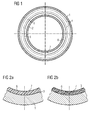
- the figure 1 is a schematic view of a ring-shaped structural element being manufactured in its mold and intended to have an abradable surface at its inner periphery.
- the figure 2a is a sectional view of a section of the ring of the figure 1 before heat treatment.
- the figure 2b is a sectional view of a section of the ring corresponding to the figure 1 after heat treatment and possibly after chemical dissolution.
- the invention consists in the shaping of a machine structural element of composite material and whose material of its abradable surface is integral with the element itself.
- the composite member is typically molded by depositing reinforcing fiber webs and injecting a resin into the mold and then heat treating to polymerize the resin.
- a filler material capable of imparting to the surface an abradability property is added locally at the surface during the introduction of the fibers and the resin.
- the concept of abradability is comparable to a surface capacity to be friable in very fine dust when friction with an element in relative motion. Typically such property can be reached when a certain porosity is reached in the material constituting the surface in question.
- the filler material is capable of generating a certain porosity in the constituent material of the structural element in order to give the surface abradability properties. This ability of the filler material to generate porosity is related to its chemical composition, its physical structure itself or a combination of both.
- the filler material may be a chemical compound such that it undergoes a change of state such as liquefaction, vaporization or even sublimation from a certain temperature that is reached during the heat treatment of polymerization of the material. constituting the structural element.
- This change of state of the filler material will generate a network of pores from the location of the filler material to the surface. This network creates the porosity necessary for the abradability of the surface.
- the filler material may also have a structure such that it forms a potential network of micro-channels, for example fibers, embedded in the material at the surface. This network will then be "taken” in the material after polymerization and may, after a possible chemical elimination, give the surface material zone a porosity.
- the filler material may also be a combination of these two types, such as polyester hollow microspheres, that is to say capable of passing into the gaseous phase.
- polyester hollow microspheres that is to say capable of passing into the gaseous phase.
- FIG. 1 An exemplary embodiment of the invention is illustrated in Figures 1, 2a and 2b .
- the figure schematically illustrates a sectional view of an outer shell of axial turbomachine compressor in the shaping phase.
- An outer ferrule of a turbomachine compressor generally has a form of a structural ring that can be assembled to other compressor stator components. Its inner surface constitutes the stator or casing portion for the corresponding mobile wheel of the compressor.
- the moving wheel consists of a row of blades on the periphery of the rotor constituting with the stator rectifier grid directly downstream a compressor stage.
- the inner surface of the ferrule surrounds the rotor vanes and is capable of coming into contact with the ends thereof under certain operating conditions.
- the inner surface of the ferrule must therefore have abradability properties in order to prevent any major deterioration of the blades or ferrule in case of contact.
- the mold comprises an outer portion 1 for the outer surface of the ferrule and an inner portion 2 for the inner surface of the ferrule.
- the ferrule is typically made of composite material comprising reinforcing fibers such as glass or carbon fibers and a thermosetting resin.
- the manufacture of the composite shell takes place as follows.
- One or more successive layers of reinforcing fibers 4 are placed in the mold.
- a transition layer 3 is then put in place.
- This sheet is advantageously of the same type as the reinforcing plies 4 but plays a particular role here insofar as the ply 3 forms an annular physical separation in the thickness of the ferrule.
- the resin typically a thermosetting resin of a type known to those skilled in the art, such as an epoxy resin, is injected into the mold.
- a filler material capable of changing state during subsequent heat treatment is also injected. It can be mixed directly with the resin so that it is injected with the resin.
- the injection of the filler material is made from the inner mold to fill the zone 6 of the ferrule.
- the injection techniques for several components known to those skilled in the art can be applied to obtain a stratification or at least a concentration gradient of the filler material from the inner surface 7.
- the filler material may be of different kinds, such as hollow microspheres of glass or talc-porosity intrinsic to the filler material - or microspheres of PTFE or any other thermoplastic polymer capable of passing into the vapor phase during the crosslinking of the resin - porosity generated during the heat treatment of polymerization.
- the size or size of the particles is important as well as the fineness of the mesh of the ply 3 because both are chosen so that the ply is essentially impervious to the particles of the filler material.
- the topping 3 thus allows selective partitioning of the volume of the shell according to its thickness.
- the filler material will therefore concentrate in a layer from the contact surface 7, the thickness of which will be determined by the position of the ply 3.
- the latter forms a porous or resin-permeable wall, but not the particles of the plating material. charge.
- a heat treatment is then applied to cure the resin of the ferrule by polymerization.
- the material of the filler particles will vaporize, creating a cloud of gaseous inclusions in the layer 6. It will be important to select the material and control the temperature rise so that the resin has already reaches a certain viscosity before the change of state, in particular the passage in the vapor phase, in order to avoid excessive degassing which could lead to insufficient porosity.
- the figure 2a is a sectional view of a segment of the ferrule of the figure 1 before polymerization. There can be seen two distinct zones 5 and 6 delimited by the topping 3 making membrane. Zone 5 contains resin and fiber batt and zone 6 contains resin enriched in filler particles.
- Zone 5 contains resin and fiber batt and zone 6 contains resin enriched in filler particles.
- Zone 2b is a view corresponding to the figure 2a after polymerization.
- the porosity in zone 6 is illustrated by the small empty spheres of resin. They correspond to the particles of charge which vaporized and thereby enlarged. They have created a cloud of gaseous inclusions in the layer 6 from the topping 3 to the surface 7 giving this surface and its wear layer abradability properties.
- a filler material forming a micro-channel network in the resin is also conceivable.
- metal fibers for example aluminum or copper fibers.
- the metal fibers remain chemically stable during the heat treatment and should then be removed by dissolution in a suitable bath.
- the aluminum fibers could be dissolved in a strong alkaline bath, for example a sodium hydroxide bath).
- the copper fibers could be dissolved in an acid bath, for example a hydrochloric acid bath. The removal of the filler material will generate porosity in the resin and impart abradability properties.
- the example described in the figures relates to an outer ring of axial turbomachine compressor.
- the element does not have to be circular.
- a segmented ferrule i.e., a series of ferrule segments, could be made. It is clear that the described principle can be applied to any structural element or machine component to have at least one surface with abradability properties.
Landscapes
- Engineering & Computer Science (AREA)
- Mechanical Engineering (AREA)
- General Engineering & Computer Science (AREA)
- Structures Of Non-Positive Displacement Pumps (AREA)
Abstract
Description
- L'invention a trait à un procédé de fabrication d'un élément structurel en matériau composite avec une surface de friction, plus particulièrement à un procédé de fabrication par moulage d'un élément structurel tel qu'une virole d'un compresseur de turbomachine axiale. L'invention a trait également à un élément structurel tel qu'une virole d'un compresseur de turbomachine axiale.
- Le document
EP 0 219 445 divulgue une virole interne d'une grille redresseur d'un compresseur d'une turbine axiale. La virole interne est en matériau composite et est constituée d'un anneau interne en structure laminée comprenant des couches de fibres en polyamide Kevlar® noyées dans une résine époxy. La virole comprend également une série de tronçons gaufrés destinés à être collés à l'anneau interne et à recevoir les pieds d'aubes. Ces tronçons sont également en matériau composite consistant en des fibres de verres noyées dans une résine. Un joint coopérant avec deux nervures du rotor est rapporté à la surface intérieure de l'anneau interne. Ce joint forme avec les deux nervures un joint à labyrinthe. La construction de la virole interne composite de ce document est complexe car elle requiert la fabrication et l'assemblage de plusieurs éléments la constituant. L'enseignement de ce document est de plus limité à une virole interne. - Le document
US 4 135 851 divulgue une garniture abradable d'une virole externe de compresseur ou de turbine axiale. La garniture est en forme d'anneau destiné à être inséré et puis fixé, par collage par exemple, à la virole vraisemblablement métallique. La garniture est formée d'un support en forme d'anneau comprenant des feuilles métalliques ondulées et d'une couche de matériau abradable fixée à la surface intérieure du support. Le support en feuilles métalliques ondulées permet de reprendre certaines déformations de la couche d'abradable, évitant ainsi d'éventuels dégâts aux têtes d'aubes du rotor et/ou à la virole lors de contact entre ces deux éléments durant le fonctionnement de la machine. Ce type de construction est également assez complexe car impliquant la réalisation de plusieurs éléments et de leur assemblage. - Différentes méthodes de fabrication de couche abradable sur une virole métallique de turbomachine sont connues.
- Par exemple le document
WO 2005/014979 divulgue un procédé permettant d'appliquer un matériau métallique sous forme de boue sur une surface par trempage, application au pinceau, par projection ou par déposition en phase vapeur et d'en contrôler la porosité durant la cuisson. Le matériau appliqué comprend des microbilles de plastiques. La couche appliquée devient poreuse durant la cuisson par vaporisation des microbilles. Ce procédé est cependant limité à la formation de couche abradable sur une virole métallique. - Les enseignements détaillés ci-avant manquent de proposer une solution simple pour la réalisation d'un élément structurel composite, tel qu'une virole de turbomachine, ayant une surface abradable destinée à entrer en friction avec un élément mobile. En effet, les solutions proposées par ces enseignements prévoient au minimum l'application séparée d'une couche abradable de nature différente de l'élément structurel et par un procédé d'application différent de celui de la fabrication de l'élément en soi. De plus, une opération de sablage de la surface de l'élément sur laquelle l'abradable est appliqué est souvent nécessaire afin d'assurer un accrochage satisfaisant.
- L'objectif de la présente invention consiste à proposer une solution plus simple et moins coûteuse pour la réalisation de tels éléments.
- L'invention consiste en un procédé de fabrication par moulage d'un élément structurel de machine, préférentiellement de stator de turbomachine axiale, l'élément structurel comportant une surface de friction pouvant entrer en contact sous certaines conditions avec un élément mobile ; comprenant les étapes suivantes :
- mise en place d'un moule ;
- remplissage du moule avec au moins un matériau sous forme pâteuse ou liquide constituant l'élément structurel ;
- ajout d'au moins un matériau de charge au niveau de la surface de friction ;
- traitement thermique de polymérisation du matériau;
le matériau de charge ayant la capacité de créer une porosité durant ou après le traitement thermique sur une épaisseur de l'élément structurel, la porosité conférant à la surface des propriétés d'abradabilité. - Ce procédé permet de conférer à l'élément structurel des propriétés d'abradabilité directement lors de sa fabrication. Il permet de s'acquitter des difficultés de fabrication séparée de l'élément structurel et d'un élément abradable et d'assemblage et de traitement de surface associés lorsqu'une surface abradable est rapportée par collage par exemple à un élément structurel. L'élément structurel ainsi fabriqué présente de plus une adhésion de la couche abradable du niveau de la force de cohésion du matériau en question, étant en fait un matériau monobloc à gradient de propriétés.
- Préférentiellement, le matériau de charge comprend des particules solides et une membrane perméable à la résine et imperméable aux particules solides est placée dans le moule avant l'ajout du matériau de charge de sorte à limiter la présence du matériau de charge à proximité de la surface de friction de l'élément structurel.
- Préférentiellement, la membrane comprend des fibres, préférentiellement des fibres de verre ou de carbone.
- Préférentiellement, le matériau de charge comprend au moins un des matériaux suivants : microbilles, préférentiellement creuses, de verre ; talc.
- Dans le cas de microbilles creuses de verre, la porosité est obtenue automatiquement.
- Préférentiellement, le matériau de charge est tel qu'il se dégrade, préférentiellement qu'il passe en phase vapeur, lors du traitement thermique.
- Préférentiellement, le matériau de charge comprend au moins un des matériaux suivants : microsphères de matériau thermoplastique, préférentiellement de PTFE ou tout autre polymère thermoplastique apte à passer en phase vapeur lors de la polymérisation de la résine.
- Dans le cas de microbilles de polyester du type CAS 260-99-71-8, l'élévation de température due à la polymérisation suffit à la dégradation du matériau de charge, créant ainsi les porosités attendues.
- Préférentiellement, le matériau de charge est fibreux, préférentiellement métallique. Ce type de matériau de charge permet d'éviter la présence de la membrane de séparation.
- Préférentiellement, le procédé comprend une étape supplémentaire après le traitement thermique consistant à dissoudre le matériau de charge fibreux métallique, préférentiellement par application d'un bain chimique approprié.
- Préférentiellement, les fibres du matériau de charge sont en aluminium et le bain chimique de dissolution est un bain alcalin fort, préférentiellement d'hydroxyde de sodium.
- Préférentiellement, les fibres du matériau de charge sont en cuivre et le bain chimique de dissolution est un bain acide, préférentiellement d'acide chlorhydrique.
- Préférentiellement, l'élément structurel est une virole interne ou externe, préférentiellement de compresseur.
- Préférentiellement, l'élément structurel est constitué de fibres structurantes, préférentiellement choisies parmi les suivantes : verre, carbone, métallique ; et de résine thermodurcissable.
- L'invention consiste également en un élément structurel de stator d'une turbomachine axiale avec rotor, l'élément structurel étant en matériau thermodurcissable et comportant une surface abradable destinée à entrer en friction avec un élément du rotor; la surface abradable étant venue de matière avec l'élément structurel.
- Préférentiellement, le matériau de l'élément structurel présente une porosité sur une épaisseur à partir de la surface, la porosité conférant à la surface au moins partiellement son abradabilité.
- Préférentiellement, l'élément structurel est une virole interne ou externe d'un compresseur de turbomachine axiale.
- Les caractéristiques de l'invention mentionnées ci-dessus, ainsi que d'autres, apparaîtront plus clairement à la lecture de la description suivante d'un exemple de réalisation, en se référant aux dessins annexés.
- La
figure 1 est une vue schématique d'un élément structurel en forme d'anneau en cours de fabrication dans son moule et destiné à présenter une surface abradable à sa périphérie intérieure. - La
figure 2a est une vue en coupe d'une section de l'anneau de lafigure 1 avant traitement thermique. - La
figure 2b est une vue en coupe d'une section de l'anneau correspondant à lafigure 1 après traitement thermique et éventuellement après dissolution chimique. - L'invention consiste en la mise à forme d'un élément structurel de machine en matériau composite et dont le matériau de sa surface abradable est venu de matière avec l'élément en soi. L'élément composite est typiquement mis à forme par moulage en déposant des nappes de fibres de renforcement et injection d'une résine dans le moule et ensuite par traitement thermique en vue de faire polymériser la résine. Un matériau de charge apte à conférer à la surface une propriété d'abradabilité est ajouté localement en surface lors de la mise en place des fibres et de la résine. La notion d'abradabilité est assimilable à une capacité de surface à être friable en très fine poussière lors de friction avec un élément en mouvement relatif. Typiquement une telle propriété peut être atteinte lorsque qu'une certaine porosité est atteinte dans le matériau constituant la surface en question.
- Le matériau de charge est apte à générer une certaine porosité dans le matériau constituant de l'élément structurel en vue de conférer à la surface des propriétés d'abradabilité. Cette capacité du matériau de charge à générer une porosité est liée à sa composition chimique, à sa structure physique même ou encore à une combinaison des deux.
- En effet, le matériau de charge peut être un composé chimique tel qu'il subisse un changement d'état comme une liquéfaction, une vaporisation ou même une sublimation à partir d'une certaine température qui soit atteinte lors du traitement thermique de polymérisation du matériau constituant l'élément structurel. Ce changement d'état du matériau de charge va générer un réseau de pores depuis la localisation du matériau de charge jusqu'à la surface. Ce réseau crée la porosité nécessaire à l'abradabilité de la surface.
- Le matériau de charge peut également présenter une structure telle qu'il forme un réseau potentiel de micro canaux, comme par exemple des fibres, noyé dans le matériau au niveau de la surface. Ce réseau sera ensuite « pris » dans le matériau après polymérisation et pourra, après une éventuelle élimination chimique, conférer à la zone de matériau en surface une porosité.
- Le matériau de charge peut également être une combinaison de ces deux types, comme par exemple des microbilles creuses de polyester, c'est-à-dire apte à passer en phase gazeuse. Lors de la polymérisation de la résine de l'élément structurel, l'enveloppe des microbilles va passer en phase vapeur et tout en libérant les microbulles d'air comprises dans les microbilles creuses, va augmenter le volume total de porosité dans le matériau.
- Un exemple de réalisation de l'invention est illustré aux
figures 1, 2a et 2b . La figure illustre de manière schématique une vue en coupe d'une virole externe de compresseur de turbomachine axiale en phase de mise à forme. Une virole externe de compresseur de turbomachine a généralement une forme d'anneau structurel apte à être assemblé à d'autres composants du stator du compresseur. Sa surface interne constitue la partie de stator ou de carter pour la roue mobile correspondante du compresseur. La roue mobile est constituée d'une rangée d'aubes sur la périphérie du rotor constituant avec la grille redresseur statorique directement en aval un étage du compresseur. La surface interne de la virole entoure les aubes rotoriques et est susceptible d'entrer en contact avec les extrémités de celles-ci dans certaines conditions de fonctionnement. La surface interne de la virole doit donc présenter des propriétés d'abradabilité en vue d'éviter toute détérioration majeure des aubes ou de la virole en cas de contact. Le moule comprend une partie extérieure 1 pour la surface extérieure de la virole et une partie intérieure 2 pour la surface intérieure de la virole. La virole est typiquement constituée de matériau composite comprenant des fibres de renforcement telles que des fibres de verre ou de carbone et une résine thermodurcissable. - La fabrication de la virole composite a lieu comme suit. Une ou plusieurs nappes successives de fibres de renforcement 4 sont mises en place dans le moule. Une nappe de transition 3 est ensuite mise en place. Cette nappe est avantageusement du même type que les nappes de renforcement 4 mais joue un rôle particulier ici dans la mesure où la nappe 3 forme une séparation physique annulaire dans l'épaisseur de la virole. La résine, typiquement une résine thermodurcissable de type connu de l'homme de l'art, comme une résine époxy, est injectée dans le moule. Un matériau de charge apte à changer d'état lors de du traitement thermique postérieur est également injecté. Il peut être mélangé directement à la résine de sorte à ce qu'il soit injecté avec la résine. Il peut être également injecté séparément avant injection de la résine, en étant retenu par la nappe de transition 3, ou en fin d'étape d'injection de la résine ou encore il peut être injecté avec la résine uniquement en fin de processus d'injection. L'injection du matériau de charge se fait à partir du moule intérieur afin de remplir la zone 6 de la virole. Les techniques d'injection pour plusieurs composants connues de l'homme de l'art peuvent être appliquées en vue d'obtenir une stratification ou à tout le moins un gradient de concentration du matériau de charge depuis la surface intérieure 7.
- Le matériau de charge peut être de différente nature, comme par exemple des microbilles creuses de verre ou de talc - porosité intrinsèque au matériau de charge - ou des microsphères de PTFE ou de tout autre polymère thermoplastique apte à passer en phase vapeur lors de la réticulation de la résine - porosité générée durant le traitement thermique de polymérisation. Le calibre ou la taille des particules est importante ainsi que la finesse du maillage de la nappe 3 car les deux sont choisis de sorte à ce que la nappe soit essentiellement imperméable aux particules du matériau de charge. Le nappage 3 permet ainsi un cloisonnement sélectif du volume de la virole selon son épaisseur. Le matériau de charge va donc se concentrer dans une couche à partir de la surface de contact 7 dont l'épaisseur sera déterminée par la position du nappage 3. Ce dernier forme une paroi poreuse ou perméable à la résine mais pas aux particules du matériau de charge.
- Un traitement thermique est ensuite appliqué afin de durcir par polymérisation la résine de la virole. Lors de ce traitement thermique, le matériau des particules de charge va vaporiser, créant ainsi un nuage d'inclusions gazeuses dans la couche 6. Il sera important de bien sélectionner le matériau et de contrôler l'élévation de température afin que la résine ait déjà atteint une certaine viscosité avant le changement d'état, en particulier le passage en phase vapeur, afin d'éviter un dégazage trop important qui pourrait conduire à une porosité insuffisante.
- La
figure 2a est une vue en coupe d'un segment de la virole de lafigure 1 avant polymérisation. On peut y voir les deux zones distinctes 5 et 6 délimitées par le nappage 3 faisant membrane. La zone 5 contient de la résine et les nappages de fibres et la zone 6 contient de la résine enrichie en particules de charges. Lafigure 2b est une vue correspondant à lafigure 2a après polymérisation. La porosité dans la zone 6 est illustrée par les petites sphères vides de résine. Elles correspondent aux particules de charge qui ont vaporisé et par là grossi. Elles ont créé un nuage d'inclusions gazeuses dans la couche 6 depuis le nappage 3 jusqu'à la surface 7 conférant à cette surface et sa couche d'usure des propriétés d'abradabilité. - D'autres types de matériau de charge sont envisageables adhérant au même principe de création de porosité.
- Comme déjà mentionné plus tôt, un matériau de charge formant un réseau de micro canaux dans la résine, stable chimiquement durant la polymérisation et apte à être enlevé par la suite est également envisageable. Typiquement on pourrait utiliser des fibres métalliques, par exemple des fibres d'aluminium ou de cuivre. Dans ce cas, il n'est plus nécessaire de prévoir de paroi de cloisonnement mais il suffit de placer les fibres en question dans la zone destinée à être abradable. Les fibres métalliques restent chimiquement stables durant le traitement thermique et il convient ensuite de les retirer par dissolution dans un bain approprié. Les fibres d'aluminium pourraient être dissoutes dans un bain alcalin fort, par exemple un bain d'hydroxyde de sodium). Les fibres de cuivre pourraient être dissoutes dans un bain d'acide, par exemple un bain d'acide chlorhydrique. L'enlèvement du matériau de charge va générer une porosité dans la résine et lui conférer des propriétés d'abradabilité.
- L'exemple décrit dans les figures concerne une virole externe de compresseur de turbomachine axiale. L'élément ne doit pas nécessairement être circulaire. Par exemple, on pourrait fabriquer une virole segmentée, c'est-à-dire une série de segments de virole. Il est clair que le principe décrit peut être appliqué à tout élément structurel ou composant de machine devant présenter au moins une surface avec des propriétés d'abradabilité.
Claims (15)
- Procédé de fabrication par moulage d'un élément structurel de machine, préférentiellement de stator de turbomachine axiale, l'élément structurel comportant une surface de friction pouvant entrer en contact sous certaines conditions avec un élément mobile ; comprenant les étapes suivantes :- mise en place d'un moule ;- remplissage du moule avec au moins un matériau sous forme pâteuse ou liquide constituant l'élément structurel ;- traitement thermique de polymérisation du matériau;caractérisé par l'étape supplémentaire suivante :- ajout d'au moins un matériau de charge au niveau de la surface de friction avant le traitement thermique, le matériau de charge ayant la capacité à créer une porosité sur une épaisseur de l'élément structurel durant ou après le traitement thermique, la porosité conférant à la surface des propriétés d'abradabilité.
- Procédé de fabrication selon la revendication précédente, caractérisé en ce que le matériau de charge comprend des particules solides et en ce qu'une membrane perméable à la résine et imperméable aux particules solides est placée dans le moule avant l'ajout du matériau de charge de sorte à limiter la présence du matériau de charge à proximité de la surface de friction de l'élément structurel.
- Procédé de fabrication selon la revendication précédente, caractérisé en ce que la membrane comprend des fibres, préférentiellement des fibres de verre ou de carbone.
- Procédé de fabrication selon l'une des revendications 2 et 3, caractérisé en ce que le matériau de charge comprend au moins un des matériaux suivants : microbilles, préférentiellement creuses, de verre ; talc.
- Procédé de fabrication selon la revendication 1, caractérisé en ce que le matériau de charge est tel qu'il se dégrade, préférentiellement qu'il passe en phase vapeur, lors du traitement thermique.
- Procédé de fabrication selon l'une des revendications 2, 3 et 5, caractérisé en ce que le matériau de charge comprend au moins un des matériaux suivants : microsphères de matériau thermoplastique, préférentiellement de PTFE ou tout autre polymère thermoplastique apte à passer en phase vapeur lors de la polymérisation de la résine.
- Procédé de fabrication selon la revendication 1, caractérisé en ce que le matériau de charge est fibreux, préférentiellement métallique.
- Procédé de fabrication selon la revendication précédente, caractérisé en ce qu'il comprend une étape supplémentaire après le traitement thermique consistant à dissoudre le matériau de charge fibreux métallique, préférentiellement par application d'un bain chimique approprié.
- Procédé de fabrication selon la revendication 7, caractérisé en ce que les fibres du matériau de charge sont en aluminium et le bain chimique de dissolution est un bain alcalin fort, préférentiellement d'hydroxyde de sodium.
- Procédé de fabrication selon la revendication 7, caractérisé en ce que les fibres du matériau de charge sont en cuivre et le bain chimique de dissolution est un bain acide, préférentiellement d'acide chlorhydrique.
- Procédé de fabrication selon l'une des revendications précédentes, caractérisé en ce que l'élément structurel est une virole interne ou externe, préférentiellement de compresseur.
- Procédé de fabrication selon l'une des revendications précédentes, caractérisé en ce que l'élément structurel est constitué de fibres structurantes, préférentiellement choisies parmi les suivantes : verre, carbone, métallique ; et de résine thermodurcissable.
- Elément structurel de stator d'une turbomachine axiale avec rotor, l'élément structurel étant en matériau thermodurcissable et comportant une surface abradable destinée à entrer en friction avec un élément du rotor ; caractérisé en ce que la surface abradable est venue de matière avec l'élément structurel.
- Elément structurel selon la revendication précédente, caractérisé en ce que le matériau de l'élément structurel présente une porosité sur une épaisseur à partir de la surface, la porosité conférant à la surface au moins partiellement son abradabilité.
- Elément structurel selon la revendication précédente, caractérisé en qu'il est une virole interne ou externe d'un compresseur de turbomachine axiale.
Priority Applications (3)
| Application Number | Priority Date | Filing Date | Title |
|---|---|---|---|
| EP08172881.8A EP2202264B1 (fr) | 2008-12-24 | 2008-12-24 | Procédé de fabrication par moulage d'un élément structurel de machine avec une surface abradable |
| CA2688697A CA2688697C (fr) | 2008-12-24 | 2009-12-14 | Procede de fabrication par moulage d'element structural de machine presentant une surface abradable, et element structural |
| US12/644,133 US8491258B2 (en) | 2008-12-24 | 2009-12-22 | Method for manufacturing by molding a machine structural element having an abradable surface, and structural element |
Applications Claiming Priority (1)
| Application Number | Priority Date | Filing Date | Title |
|---|---|---|---|
| EP08172881.8A EP2202264B1 (fr) | 2008-12-24 | 2008-12-24 | Procédé de fabrication par moulage d'un élément structurel de machine avec une surface abradable |
Publications (2)
| Publication Number | Publication Date |
|---|---|
| EP2202264A1 true EP2202264A1 (fr) | 2010-06-30 |
| EP2202264B1 EP2202264B1 (fr) | 2018-04-18 |
Family
ID=40578653
Family Applications (1)
| Application Number | Title | Priority Date | Filing Date |
|---|---|---|---|
| EP08172881.8A Active EP2202264B1 (fr) | 2008-12-24 | 2008-12-24 | Procédé de fabrication par moulage d'un élément structurel de machine avec une surface abradable |
Country Status (3)
| Country | Link |
|---|---|
| US (1) | US8491258B2 (fr) |
| EP (1) | EP2202264B1 (fr) |
| CA (1) | CA2688697C (fr) |
Cited By (5)
| Publication number | Priority date | Publication date | Assignee | Title |
|---|---|---|---|---|
| EP2586989A1 (fr) * | 2011-10-27 | 2013-05-01 | Techspace Aero S.A. | Virole composite co-injectée de compresseur de turbomachine axiale |
| CN104039523A (zh) * | 2011-08-16 | 2014-09-10 | 通用电气公司 | 面板及其生产工艺 |
| EP2813672A1 (fr) * | 2013-06-13 | 2014-12-17 | Composite Industrie | Pièce de matériau abradable pour la fabrication d'un secteur de joint annulaire abradable pour turbomachine et procédé de fabrication d'une telle pièce |
| WO2016203141A1 (fr) | 2015-06-18 | 2016-12-22 | Safran Aircraft Engines | Dispositif de revetement d'un carter annulaire de turbomachine |
| US9587506B2 (en) | 2013-06-13 | 2017-03-07 | Composite Industrie | Segment of an abradable ring seal for a turbomachine, and process for the manufacture of such a piece |
Families Citing this family (9)
| Publication number | Priority date | Publication date | Assignee | Title |
|---|---|---|---|---|
| EP3252174B1 (fr) * | 2012-10-15 | 2020-07-01 | Life Technologies Corporation | Compositions, procédés, systèmes et kits pour l'enrichissement d'acides nucléiques cibles |
| US9598973B2 (en) | 2012-11-28 | 2017-03-21 | General Electric Company | Seal systems for use in turbomachines and methods of fabricating the same |
| WO2014120117A1 (fr) * | 2013-01-29 | 2014-08-07 | United Technologies Corporation | Matériau de frottement de lame |
| US9957819B2 (en) * | 2014-03-28 | 2018-05-01 | United Technologies Corporation | Abrasive tip blade manufacture methods |
| US10643290B2 (en) * | 2015-10-23 | 2020-05-05 | Bell Helicopter Textron Inc. | Identification tags for tracking manufacturing of aircraft parts |
| US20210130243A1 (en) * | 2017-02-17 | 2021-05-06 | Oerlikon Metco (Us) Inc. | Fiber porosity forming fillers in thermal spray powders and coatings and method making and using the same |
| FR3102948B1 (fr) * | 2019-11-12 | 2022-06-24 | Safran Nacelles | Pièce à résistance à l’usure par frottement améliorée |
| FR3106612B1 (fr) * | 2020-01-29 | 2022-07-22 | Safran Aircraft Engines | Carter de turbomachine d’aeronef et son procede de fabrication |
| CN114055805B (zh) * | 2020-08-10 | 2023-09-08 | 中国航发商用航空发动机有限责任公司 | 航空发动机风扇易磨环的制造方法 |
Citations (7)
| Publication number | Priority date | Publication date | Assignee | Title |
|---|---|---|---|---|
| US4135851A (en) | 1977-05-27 | 1979-01-23 | The United States Of America As Represented By The Administrator Of The National Aeronautics And Space Administration | Composite seal for turbomachinery |
| DE3404479A1 (de) * | 1984-02-08 | 1985-08-08 | Siemens AG, 1000 Berlin und 8000 München | Verfahren zur herstellung eines leichtwerkstoffes |
| EP0219445A1 (fr) | 1985-09-30 | 1987-04-22 | United Technologies Corporation | Stator pour un compresseur ayant une virole intérieure en matériau composé |
| EP0414570A2 (fr) * | 1989-08-25 | 1991-02-27 | Mitsui Petrochemical Industries, Ltd. | Matériau pour fabrication de la surface intérieure d'un carter d'un moteur à turboréacteur et procédé pour sa fabrication |
| EP0437136A2 (fr) * | 1990-01-10 | 1991-07-17 | Matra Defense | Procédé de fabrication d'article imprégné et application du procédé à la fabrication de composants de paliers rotatifs |
| US5388959A (en) * | 1993-08-23 | 1995-02-14 | General Electric Company | Seal including a non-metallic abradable material |
| WO2005014979A1 (fr) | 2003-08-12 | 2005-02-17 | Mtu Aero Engines Gmbh | Revetement de rodage pour turbines a gaz compose d'un materiau titane-aluminium |
Family Cites Families (11)
| Publication number | Priority date | Publication date | Assignee | Title |
|---|---|---|---|---|
| GB791568A (en) * | 1956-03-26 | 1958-03-05 | Gen Motors Corp | Improvements in axial flow compressors |
| US3547455A (en) * | 1969-05-02 | 1970-12-15 | Gen Electric | Rotary seal including organic abradable material |
| US4460185A (en) * | 1982-08-23 | 1984-07-17 | General Electric Company | Seal including a non-metallic abradable material |
| US5304032A (en) * | 1991-07-22 | 1994-04-19 | Bosna Alexander A | Abradable non-metallic seal for rotating turbine engines |
| US5472315A (en) * | 1993-11-09 | 1995-12-05 | Sundstrand Corporation | Abradable coating in a gas turbine engine |
| US5759019A (en) * | 1994-02-14 | 1998-06-02 | Steven M. Wood | Progressive cavity pumps using composite materials |
| US6352264B1 (en) * | 1999-12-17 | 2002-03-05 | United Technologies Corporation | Abradable seal having improved properties |
| US6334617B1 (en) * | 2000-03-02 | 2002-01-01 | United Technologies Corporation | Composite abradable material |
| US6844392B2 (en) * | 2000-08-29 | 2005-01-18 | Andrew W. Suman | Abradable dry powder coatings, methods for making and coating, and coated articles therefrom |
| FR2887890B1 (fr) * | 2005-06-30 | 2007-10-12 | Snecma | Composition de materiau abradable, piece thermomecanique ou carter comprenant un revetement et procede de fabrication ou de reparation d'un revetement presentant cette composition |
| US20100124616A1 (en) * | 2008-11-19 | 2010-05-20 | General Electric Company | Method of forming an abradable coating |
-
2008
- 2008-12-24 EP EP08172881.8A patent/EP2202264B1/fr active Active
-
2009
- 2009-12-14 CA CA2688697A patent/CA2688697C/fr not_active Expired - Fee Related
- 2009-12-22 US US12/644,133 patent/US8491258B2/en not_active Expired - Fee Related
Patent Citations (7)
| Publication number | Priority date | Publication date | Assignee | Title |
|---|---|---|---|---|
| US4135851A (en) | 1977-05-27 | 1979-01-23 | The United States Of America As Represented By The Administrator Of The National Aeronautics And Space Administration | Composite seal for turbomachinery |
| DE3404479A1 (de) * | 1984-02-08 | 1985-08-08 | Siemens AG, 1000 Berlin und 8000 München | Verfahren zur herstellung eines leichtwerkstoffes |
| EP0219445A1 (fr) | 1985-09-30 | 1987-04-22 | United Technologies Corporation | Stator pour un compresseur ayant une virole intérieure en matériau composé |
| EP0414570A2 (fr) * | 1989-08-25 | 1991-02-27 | Mitsui Petrochemical Industries, Ltd. | Matériau pour fabrication de la surface intérieure d'un carter d'un moteur à turboréacteur et procédé pour sa fabrication |
| EP0437136A2 (fr) * | 1990-01-10 | 1991-07-17 | Matra Defense | Procédé de fabrication d'article imprégné et application du procédé à la fabrication de composants de paliers rotatifs |
| US5388959A (en) * | 1993-08-23 | 1995-02-14 | General Electric Company | Seal including a non-metallic abradable material |
| WO2005014979A1 (fr) | 2003-08-12 | 2005-02-17 | Mtu Aero Engines Gmbh | Revetement de rodage pour turbines a gaz compose d'un materiau titane-aluminium |
Cited By (10)
| Publication number | Priority date | Publication date | Assignee | Title |
|---|---|---|---|---|
| CN104039523A (zh) * | 2011-08-16 | 2014-09-10 | 通用电气公司 | 面板及其生产工艺 |
| US9421703B2 (en) | 2011-08-16 | 2016-08-23 | General Electric Company | Panels and processes therefor |
| CN104039523B (zh) * | 2011-08-16 | 2017-06-09 | 通用电气公司 | 面板及其生产工艺 |
| EP2586989A1 (fr) * | 2011-10-27 | 2013-05-01 | Techspace Aero S.A. | Virole composite co-injectée de compresseur de turbomachine axiale |
| US9644486B2 (en) | 2011-10-27 | 2017-05-09 | Techspace Aero S.A. | Co-injected composite shell for an axial turbomachine compressor |
| EP2813672A1 (fr) * | 2013-06-13 | 2014-12-17 | Composite Industrie | Pièce de matériau abradable pour la fabrication d'un secteur de joint annulaire abradable pour turbomachine et procédé de fabrication d'une telle pièce |
| FR3007063A1 (fr) * | 2013-06-13 | 2014-12-19 | Composite Ind | Piece de materiau abradable pour la fabrication d'un secteur de joint annulaire abradable pour turbomachine et procede de fabrication d'une telle piece |
| US9533454B2 (en) | 2013-06-13 | 2017-01-03 | Composite Industrie | Piece of abradable material for the manufacture of a segment of an abradable ring seal for a turbomachine, and process for the manufacture of such a piece |
| US9587506B2 (en) | 2013-06-13 | 2017-03-07 | Composite Industrie | Segment of an abradable ring seal for a turbomachine, and process for the manufacture of such a piece |
| WO2016203141A1 (fr) | 2015-06-18 | 2016-12-22 | Safran Aircraft Engines | Dispositif de revetement d'un carter annulaire de turbomachine |
Also Published As
| Publication number | Publication date |
|---|---|
| CA2688697C (fr) | 2015-04-21 |
| CA2688697A1 (fr) | 2010-06-24 |
| EP2202264B1 (fr) | 2018-04-18 |
| US8491258B2 (en) | 2013-07-23 |
| US20110002779A1 (en) | 2011-01-06 |
Similar Documents
| Publication | Publication Date | Title |
|---|---|---|
| EP2202264B1 (fr) | Procédé de fabrication par moulage d'un élément structurel de machine avec une surface abradable | |
| EP3393764B1 (fr) | Carter allégé en matériau composite et son procédé de fabrication | |
| CA2862685C (fr) | Preforme fibreuse d'une aube de turbomachine en materiau composite a plate-forme integree, et son procede de realisation | |
| WO2020049254A1 (fr) | Carter en materiau composite avec raidisseur integre | |
| CA2957834C (fr) | Aube de redresseur en materiau composite pour moteur a turbine a gaz et son procede de fabrication | |
| FR3074088A1 (fr) | Carter en materiau composite renforce et son procede de fabrication | |
| FR3081370A1 (fr) | Corps d'aube et aube en materiau composite ayant un renfort fibreux compose d'un tissage tridimensionnel et de fibres courtes et leur procede de fabrication | |
| EP3827119B1 (fr) | Texture fibreuse pour carter en matériau composite à résistance à l'impact améliorée | |
| EP2528727A1 (fr) | Methode de fabrication d'une aube a canaux internes en composite et aube de turbomachine en composite | |
| EP3927529B1 (fr) | Reparation ou reprise de fabrication d'une piece en materiau composite a renfort fibreux tisse tridimensionnel | |
| WO2021123652A9 (fr) | Aube de soufflante ou d'helice pour une turbomachine d'aeronef et son procede de fabrication | |
| EP2813672A1 (fr) | Pièce de matériau abradable pour la fabrication d'un secteur de joint annulaire abradable pour turbomachine et procédé de fabrication d'une telle pièce | |
| EP3827118B1 (fr) | Texture fibreuse pour carter en matériau composite à résistance au cisaillement ameliorée | |
| EP3676431B1 (fr) | Texture fibreuse tissee pour la formation d'une preforme de carter | |
| WO2020260804A1 (fr) | Piece de revolution en materiau composite ayant une resistance au delaminage amelioree | |
| WO2018041992A1 (fr) | Préforme, pièce d'ossature et procédé de fabrication d'une telle préforme | |
| WO2022258917A1 (fr) | Preforme fibreuse pour la fabrication d'un carter annulaire en materiau composite pour une turbomachine | |
| EP3648960B1 (fr) | Procede de fabrication d'un panneau composite | |
| EP4504499A1 (fr) | Pièce de révolution en matériau composite a capacité de rétention améliorée | |
| FR3141873A1 (fr) | Texture fibreuse comprenant deux portions de déploiement | |
| FR3162017A1 (fr) | Procédé de fabrication d’une pièce de révolution en matériau composite avec portion à ténacité réduite inter-plis | |
| WO2025104409A1 (fr) | Bouchons solubles pour creation de cavite borgne dans un aubage composite | |
| FR3053625A1 (fr) | Helice de groupe moto-ventilateur et procede de fabrication d’une telle helice | |
| FR3162016A1 (fr) | Procédé de fabrication d’une pièce de révolution en matériau composite avec l’insertion d’un antiadhésif inter-plis | |
| FR3141872A1 (fr) | Texture fibreuse comprenant deux portions de déploiement |
Legal Events
| Date | Code | Title | Description |
|---|---|---|---|
| PUAI | Public reference made under article 153(3) epc to a published international application that has entered the european phase |
Free format text: ORIGINAL CODE: 0009012 |
|
| AK | Designated contracting states |
Kind code of ref document: A1 Designated state(s): AT BE BG CH CY CZ DE DK EE ES FI FR GB GR HR HU IE IS IT LI LT LU LV MC MT NL NO PL PT RO SE SI SK TR |
|
| AX | Request for extension of the european patent |
Extension state: AL BA MK RS |
|
| AKY | No designation fees paid | ||
| 17P | Request for examination filed |
Effective date: 20100908 |
|
| RBV | Designated contracting states (corrected) |
Designated state(s): AT BE BG CH CY CZ DE DK EE ES FI FR GB GR HR HU IE IS IT LI LT LU LV MC MT NL NO PL PT RO SE SI SK TR |
|
| 17Q | First examination report despatched |
Effective date: 20110310 |
|
| REG | Reference to a national code |
Ref country code: DE Ref legal event code: R108 Ref document number: 602008054868 Country of ref document: DE Effective date: 20110208 Ref country code: DE Ref legal event code: R108 Effective date: 20110208 Ref country code: DE Ref legal event code: 8566 |
|
| RAP1 | Party data changed (applicant data changed or rights of an application transferred) |
Owner name: SAFRAN AERO BOOSTERS SA |
|
| STAA | Information on the status of an ep patent application or granted ep patent |
Free format text: STATUS: EXAMINATION IS IN PROGRESS |
|
| REG | Reference to a national code |
Ref country code: DE Ref legal event code: R079 Ref document number: 602008054868 Country of ref document: DE Free format text: PREVIOUS MAIN CLASS: C08J0009060000 Ipc: F01D0005000000 |
|
| GRAP | Despatch of communication of intention to grant a patent |
Free format text: ORIGINAL CODE: EPIDOSNIGR1 |
|
| STAA | Information on the status of an ep patent application or granted ep patent |
Free format text: STATUS: GRANT OF PATENT IS INTENDED |
|
| RIC1 | Information provided on ipc code assigned before grant |
Ipc: B29C 44/56 20060101ALI20171012BHEP Ipc: F01D 11/12 20060101ALI20171012BHEP Ipc: F01D 5/00 20060101AFI20171012BHEP Ipc: F01D 9/04 20060101ALI20171012BHEP Ipc: B29C 44/06 20060101ALI20171012BHEP Ipc: C08J 9/26 20060101ALI20171012BHEP |
|
| INTG | Intention to grant announced |
Effective date: 20171025 |
|
| GRAS | Grant fee paid |
Free format text: ORIGINAL CODE: EPIDOSNIGR3 |
|
| GRAA | (expected) grant |
Free format text: ORIGINAL CODE: 0009210 |
|
| STAA | Information on the status of an ep patent application or granted ep patent |
Free format text: STATUS: THE PATENT HAS BEEN GRANTED |
|
| AK | Designated contracting states |
Kind code of ref document: B1 Designated state(s): AT BE BG CH CY CZ DE DK EE ES FI FR GB GR HR HU IE IS IT LI LT LU LV MC MT NL NO PL PT RO SE SI SK TR |
|
| REG | Reference to a national code |
Ref country code: GB Ref legal event code: FG4D Free format text: NOT ENGLISH |
|
| REG | Reference to a national code |
Ref country code: CH Ref legal event code: EP |
|
| REG | Reference to a national code |
Ref country code: AT Ref legal event code: REF Ref document number: 990693 Country of ref document: AT Kind code of ref document: T Effective date: 20180515 |
|
| REG | Reference to a national code |
Ref country code: IE Ref legal event code: FG4D Free format text: LANGUAGE OF EP DOCUMENT: FRENCH |
|
| REG | Reference to a national code |
Ref country code: DE Ref legal event code: R096 Ref document number: 602008054868 Country of ref document: DE |
|
| REG | Reference to a national code |
Ref country code: NL Ref legal event code: MP Effective date: 20180418 |
|
| REG | Reference to a national code |
Ref country code: LT Ref legal event code: MG4D |
|
| PG25 | Lapsed in a contracting state [announced via postgrant information from national office to epo] |
Ref country code: NL Free format text: LAPSE BECAUSE OF FAILURE TO SUBMIT A TRANSLATION OF THE DESCRIPTION OR TO PAY THE FEE WITHIN THE PRESCRIBED TIME-LIMIT Effective date: 20180418 |
|
| PG25 | Lapsed in a contracting state [announced via postgrant information from national office to epo] |
Ref country code: ES Free format text: LAPSE BECAUSE OF FAILURE TO SUBMIT A TRANSLATION OF THE DESCRIPTION OR TO PAY THE FEE WITHIN THE PRESCRIBED TIME-LIMIT Effective date: 20180418 Ref country code: LT Free format text: LAPSE BECAUSE OF FAILURE TO SUBMIT A TRANSLATION OF THE DESCRIPTION OR TO PAY THE FEE WITHIN THE PRESCRIBED TIME-LIMIT Effective date: 20180418 Ref country code: NO Free format text: LAPSE BECAUSE OF FAILURE TO SUBMIT A TRANSLATION OF THE DESCRIPTION OR TO PAY THE FEE WITHIN THE PRESCRIBED TIME-LIMIT Effective date: 20180718 Ref country code: FI Free format text: LAPSE BECAUSE OF FAILURE TO SUBMIT A TRANSLATION OF THE DESCRIPTION OR TO PAY THE FEE WITHIN THE PRESCRIBED TIME-LIMIT Effective date: 20180418 Ref country code: BG Free format text: LAPSE BECAUSE OF FAILURE TO SUBMIT A TRANSLATION OF THE DESCRIPTION OR TO PAY THE FEE WITHIN THE PRESCRIBED TIME-LIMIT Effective date: 20180718 Ref country code: PL Free format text: LAPSE BECAUSE OF FAILURE TO SUBMIT A TRANSLATION OF THE DESCRIPTION OR TO PAY THE FEE WITHIN THE PRESCRIBED TIME-LIMIT Effective date: 20180418 Ref country code: SE Free format text: LAPSE BECAUSE OF FAILURE TO SUBMIT A TRANSLATION OF THE DESCRIPTION OR TO PAY THE FEE WITHIN THE PRESCRIBED TIME-LIMIT Effective date: 20180418 |
|
| PG25 | Lapsed in a contracting state [announced via postgrant information from national office to epo] |
Ref country code: GR Free format text: LAPSE BECAUSE OF FAILURE TO SUBMIT A TRANSLATION OF THE DESCRIPTION OR TO PAY THE FEE WITHIN THE PRESCRIBED TIME-LIMIT Effective date: 20180719 Ref country code: LV Free format text: LAPSE BECAUSE OF FAILURE TO SUBMIT A TRANSLATION OF THE DESCRIPTION OR TO PAY THE FEE WITHIN THE PRESCRIBED TIME-LIMIT Effective date: 20180418 Ref country code: HR Free format text: LAPSE BECAUSE OF FAILURE TO SUBMIT A TRANSLATION OF THE DESCRIPTION OR TO PAY THE FEE WITHIN THE PRESCRIBED TIME-LIMIT Effective date: 20180418 |
|
| REG | Reference to a national code |
Ref country code: AT Ref legal event code: MK05 Ref document number: 990693 Country of ref document: AT Kind code of ref document: T Effective date: 20180418 |
|
| PG25 | Lapsed in a contracting state [announced via postgrant information from national office to epo] |
Ref country code: PT Free format text: LAPSE BECAUSE OF FAILURE TO SUBMIT A TRANSLATION OF THE DESCRIPTION OR TO PAY THE FEE WITHIN THE PRESCRIBED TIME-LIMIT Effective date: 20180820 |
|
| REG | Reference to a national code |
Ref country code: DE Ref legal event code: R097 Ref document number: 602008054868 Country of ref document: DE |
|
| PG25 | Lapsed in a contracting state [announced via postgrant information from national office to epo] |
Ref country code: CZ Free format text: LAPSE BECAUSE OF FAILURE TO SUBMIT A TRANSLATION OF THE DESCRIPTION OR TO PAY THE FEE WITHIN THE PRESCRIBED TIME-LIMIT Effective date: 20180418 Ref country code: RO Free format text: LAPSE BECAUSE OF FAILURE TO SUBMIT A TRANSLATION OF THE DESCRIPTION OR TO PAY THE FEE WITHIN THE PRESCRIBED TIME-LIMIT Effective date: 20180418 Ref country code: SK Free format text: LAPSE BECAUSE OF FAILURE TO SUBMIT A TRANSLATION OF THE DESCRIPTION OR TO PAY THE FEE WITHIN THE PRESCRIBED TIME-LIMIT Effective date: 20180418 Ref country code: DK Free format text: LAPSE BECAUSE OF FAILURE TO SUBMIT A TRANSLATION OF THE DESCRIPTION OR TO PAY THE FEE WITHIN THE PRESCRIBED TIME-LIMIT Effective date: 20180418 Ref country code: EE Free format text: LAPSE BECAUSE OF FAILURE TO SUBMIT A TRANSLATION OF THE DESCRIPTION OR TO PAY THE FEE WITHIN THE PRESCRIBED TIME-LIMIT Effective date: 20180418 Ref country code: AT Free format text: LAPSE BECAUSE OF FAILURE TO SUBMIT A TRANSLATION OF THE DESCRIPTION OR TO PAY THE FEE WITHIN THE PRESCRIBED TIME-LIMIT Effective date: 20180418 |
|
| PLBE | No opposition filed within time limit |
Free format text: ORIGINAL CODE: 0009261 |
|
| STAA | Information on the status of an ep patent application or granted ep patent |
Free format text: STATUS: NO OPPOSITION FILED WITHIN TIME LIMIT |
|
| PG25 | Lapsed in a contracting state [announced via postgrant information from national office to epo] |
Ref country code: IT Free format text: LAPSE BECAUSE OF FAILURE TO SUBMIT A TRANSLATION OF THE DESCRIPTION OR TO PAY THE FEE WITHIN THE PRESCRIBED TIME-LIMIT Effective date: 20180418 |
|
| 26N | No opposition filed |
Effective date: 20190121 |
|
| PG25 | Lapsed in a contracting state [announced via postgrant information from national office to epo] |
Ref country code: SI Free format text: LAPSE BECAUSE OF FAILURE TO SUBMIT A TRANSLATION OF THE DESCRIPTION OR TO PAY THE FEE WITHIN THE PRESCRIBED TIME-LIMIT Effective date: 20180418 |
|
| REG | Reference to a national code |
Ref country code: CH Ref legal event code: PL |
|
| PG25 | Lapsed in a contracting state [announced via postgrant information from national office to epo] |
Ref country code: MC Free format text: LAPSE BECAUSE OF FAILURE TO SUBMIT A TRANSLATION OF THE DESCRIPTION OR TO PAY THE FEE WITHIN THE PRESCRIBED TIME-LIMIT Effective date: 20180418 Ref country code: LU Free format text: LAPSE BECAUSE OF NON-PAYMENT OF DUE FEES Effective date: 20181224 |
|
| REG | Reference to a national code |
Ref country code: IE Ref legal event code: MM4A |
|
| PG25 | Lapsed in a contracting state [announced via postgrant information from national office to epo] |
Ref country code: IE Free format text: LAPSE BECAUSE OF NON-PAYMENT OF DUE FEES Effective date: 20181224 |
|
| PG25 | Lapsed in a contracting state [announced via postgrant information from national office to epo] |
Ref country code: LI Free format text: LAPSE BECAUSE OF NON-PAYMENT OF DUE FEES Effective date: 20181231 Ref country code: CH Free format text: LAPSE BECAUSE OF NON-PAYMENT OF DUE FEES Effective date: 20181231 |
|
| PG25 | Lapsed in a contracting state [announced via postgrant information from national office to epo] |
Ref country code: MT Free format text: LAPSE BECAUSE OF FAILURE TO SUBMIT A TRANSLATION OF THE DESCRIPTION OR TO PAY THE FEE WITHIN THE PRESCRIBED TIME-LIMIT Effective date: 20180418 |
|
| PGFP | Annual fee paid to national office [announced via postgrant information from national office to epo] |
Ref country code: DE Payment date: 20191119 Year of fee payment: 12 |
|
| PGFP | Annual fee paid to national office [announced via postgrant information from national office to epo] |
Ref country code: FR Payment date: 20191120 Year of fee payment: 12 |
|
| PG25 | Lapsed in a contracting state [announced via postgrant information from national office to epo] |
Ref country code: TR Free format text: LAPSE BECAUSE OF FAILURE TO SUBMIT A TRANSLATION OF THE DESCRIPTION OR TO PAY THE FEE WITHIN THE PRESCRIBED TIME-LIMIT Effective date: 20180418 |
|
| PGFP | Annual fee paid to national office [announced via postgrant information from national office to epo] |
Ref country code: GB Payment date: 20191122 Year of fee payment: 12 |
|
| PG25 | Lapsed in a contracting state [announced via postgrant information from national office to epo] |
Ref country code: HU Free format text: LAPSE BECAUSE OF FAILURE TO SUBMIT A TRANSLATION OF THE DESCRIPTION OR TO PAY THE FEE WITHIN THE PRESCRIBED TIME-LIMIT; INVALID AB INITIO Effective date: 20081224 Ref country code: CY Free format text: LAPSE BECAUSE OF FAILURE TO SUBMIT A TRANSLATION OF THE DESCRIPTION OR TO PAY THE FEE WITHIN THE PRESCRIBED TIME-LIMIT Effective date: 20180418 |
|
| PG25 | Lapsed in a contracting state [announced via postgrant information from national office to epo] |
Ref country code: IS Free format text: LAPSE BECAUSE OF FAILURE TO SUBMIT A TRANSLATION OF THE DESCRIPTION OR TO PAY THE FEE WITHIN THE PRESCRIBED TIME-LIMIT Effective date: 20180818 |
|
| REG | Reference to a national code |
Ref country code: DE Ref legal event code: R119 Ref document number: 602008054868 Country of ref document: DE |
|
| GBPC | Gb: european patent ceased through non-payment of renewal fee |
Effective date: 20201224 |
|
| PG25 | Lapsed in a contracting state [announced via postgrant information from national office to epo] |
Ref country code: FR Free format text: LAPSE BECAUSE OF NON-PAYMENT OF DUE FEES Effective date: 20201231 |
|
| PG25 | Lapsed in a contracting state [announced via postgrant information from national office to epo] |
Ref country code: GB Free format text: LAPSE BECAUSE OF NON-PAYMENT OF DUE FEES Effective date: 20201224 Ref country code: DE Free format text: LAPSE BECAUSE OF NON-PAYMENT OF DUE FEES Effective date: 20210701 |
|
| PGFP | Annual fee paid to national office [announced via postgrant information from national office to epo] |
Ref country code: BE Payment date: 20251224 Year of fee payment: 18 |