EP2202138A2 - Saddle-riding vehicle - Google Patents
Saddle-riding vehicle Download PDFInfo
- Publication number
- EP2202138A2 EP2202138A2 EP09014755A EP09014755A EP2202138A2 EP 2202138 A2 EP2202138 A2 EP 2202138A2 EP 09014755 A EP09014755 A EP 09014755A EP 09014755 A EP09014755 A EP 09014755A EP 2202138 A2 EP2202138 A2 EP 2202138A2
- Authority
- EP
- European Patent Office
- Prior art keywords
- radiator
- saddle
- footboard
- vehicle body
- main surface
- Prior art date
- Legal status (The legal status is an assumption and is not a legal conclusion. Google has not performed a legal analysis and makes no representation as to the accuracy of the status listed.)
- Granted
Links
Images



Classifications
-
- B—PERFORMING OPERATIONS; TRANSPORTING
- B62—LAND VEHICLES FOR TRAVELLING OTHERWISE THAN ON RAILS
- B62J—CYCLE SADDLES OR SEATS; AUXILIARY DEVICES OR ACCESSORIES SPECIALLY ADAPTED TO CYCLES AND NOT OTHERWISE PROVIDED FOR, e.g. ARTICLE CARRIERS OR CYCLE PROTECTORS
- B62J17/00—Weather guards for riders; Fairings or stream-lining parts not otherwise provided for
- B62J17/02—Weather guards for riders; Fairings or stream-lining parts not otherwise provided for shielding only the rider's front
-
- B—PERFORMING OPERATIONS; TRANSPORTING
- B62—LAND VEHICLES FOR TRAVELLING OTHERWISE THAN ON RAILS
- B62J—CYCLE SADDLES OR SEATS; AUXILIARY DEVICES OR ACCESSORIES SPECIALLY ADAPTED TO CYCLES AND NOT OTHERWISE PROVIDED FOR, e.g. ARTICLE CARRIERS OR CYCLE PROTECTORS
- B62J17/00—Weather guards for riders; Fairings or stream-lining parts not otherwise provided for
- B62J17/10—Ventilation or air guiding devices forming part of fairings
-
- B—PERFORMING OPERATIONS; TRANSPORTING
- B62—LAND VEHICLES FOR TRAVELLING OTHERWISE THAN ON RAILS
- B62J—CYCLE SADDLES OR SEATS; AUXILIARY DEVICES OR ACCESSORIES SPECIALLY ADAPTED TO CYCLES AND NOT OTHERWISE PROVIDED FOR, e.g. ARTICLE CARRIERS OR CYCLE PROTECTORS
- B62J41/00—Arrangements of radiators, coolant hoses or pipes on cycles
-
- B—PERFORMING OPERATIONS; TRANSPORTING
- B62—LAND VEHICLES FOR TRAVELLING OTHERWISE THAN ON RAILS
- B62K—CYCLES; CYCLE FRAMES; CYCLE STEERING DEVICES; RIDER-OPERATED TERMINAL CONTROLS SPECIALLY ADAPTED FOR CYCLES; CYCLE AXLE SUSPENSIONS; CYCLE SIDECARS, FORECARS, OR THE LIKE
- B62K2202/00—Motorised scooters
Definitions
- the present invention relates to a saddle-riding vehicle wherein a radiator is placed underneath a footboard on which a rider's feet are rested.
- radiators are widely used for cooling a coolant that has absorbed the heat of an engine.
- the radiator has a main surface.
- the main surface is formed by a cooling tube through which the coolant flows and a cooling fin adjacent to the cooling tube.
- the radiator emits the heat of the coolant to a cooling draft flowing in from the main surface and passing through the radiator.
- This type of radiator is used in a saddle-riding vehicle having a footboard on which rest the rider's feet, or a so-called scooter-type two-wheeled motor vehicle.
- a technique is known in which a flat plate-shaped radiator is placed underneath the footboard in a scooter-type two-wheeled motor vehicle. It is difficult to ensure space for the upright mounting of a radiator underneath the footboard. Therefore, the radiator is laid horizontally underneath the footboard.
- the main surface is arranged facing downward, and the cooling draft flows toward the radiator from the front of the vehicle body. Therefore, much of the cooling draft does not flow orthogonal to the main surface or enter into the radiator from the main surface, but rather flows toward the rear of the vehicle body along the main surface. Therefore, this type of radiator has a problem in that heat exchange cannot be performed efficiently.
- the present invention was devised in view of such circumstances.
- a saddle-riding vehicle comprising: a vehicle body and a driving source; a front cover part being provided with a front opening which opens toward a front of the vehicle body, said front cover part comprising a ventilation duct configured to pass air that has flowed in from the front opening toward a radiator configured to cool the driving source; a footboard part on which rider's feet can be rested, the footboard part extending toward a rear of the vehicle body from a rear part of the front cover part; and the radiator being placed lower than the footboard part, with a main surface of the radiator being oriented horizontally or inclined, wherein at least part of the main surface is positioned farther forward in the vehicle body than a downward imaginary extension surface of a portion of the front cover part constituting a rear wall of the ventilation duct.
- the radiator is placed lower than the footboard part.
- the front of the radiator is covered by a wind guard cover.
- the main surface of the radiator is arranged in a horizontal or inclined orientation. At least part of the main surface of the radiator is positioned farther forward in the vehicle body than the downward imaginary extension surface of the portion of the front cover part constituting the rear wall of the ventilation duct provided to the front cover part. Therefore, air passing through the ventilation duct flows mostly orthogonal to the main surface of the radiator, and the air is fed efficiently into the radiator. Heat exchange can thereby be performed efficiently in the radiator.
- a down frame extends downward from a steering head pipe, and the front cover part encloses a periphery of the down frame and, preferably, is separated from the down frame.
- a front wheel is attached to the vehicle body in front of the front cover part, and the front opening is positioned higher than the front wheel.
- a side frame extends toward the rear of the vehicle body from a bottom part of the down frame and, preferably, the driving source is swingably attached to the side frame.
- a bottom part of the front cover part constitutes the ventilation duct, and/or a front of the radiator is covered by a wind guard cover extending downward from a bottom edge of the front opening, and/or an air blower is configured to blow air to the radiator, the air blower being preferably placed in vertical alignment with the radiator.
- the air blower is placed above the main surface of the radiator.
- the air blower is configured to blow air downward from above the radiator.
- a lower cover part extends toward the rear of the vehicle body from a bottom part of the wind guard cover in a lower position than the footboard part
- the main surface of the radiator represents a top surface of the radiator
- the radiator has a bottom surface provided on a side opposite the main surface, and at least a portion of the bottom surface and both sides of the radiator are preferably covered by the lower cover part, and, preferably, a bottom opening that opens downward is provided in a portion of the lower cover part that faces the bottom surface.
- the footboard part is shaped as a flat plate.
- the footboard part comprises a pair of flat plate parts and a convex part preferably formed into an upward convex shape, the convex part extends in longitudinal direction of the vehicle body between the pair of flat plate parts, a down frame preferably extends toward the rear of the vehicle body along a space provided on the inside of the convex part, and widths of the pair of flat plate parts in vehicle width direction are preferably greater than a width of the convex part.
- the front opening is positioned higher than the radiator.
- the main surface of the radiator is substantially orthogonal to a direction in which air flows through the ventilation duct.
- a wind guard member is placed below the footboard part and, preferably, extends toward the footboard part from a rear portion of the main surface of the radiator.
- a seat on which a rider can sit is provided and a fuel tank configured to store fuel to be supplied to the driving source is placed below the seat.
- the radiator has a radiator core through which cooling water flows and at least one radiator tank configured to store the cooling water, and the radiator tank is preferably placed on a side of the radiator core.
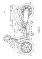
- FIG. 1 is a left side view of a two-wheeled motor vehicle 10 as a saddle-riding vehicle according to the present embodiment.
- a footrest space S1 is formed in the two-wheeled motor vehicle 10 in front of a seat 25 on which a rider sits, as illustrated in FIG. 1 .
- a footboard 52 (footboard part) is placed below the footrest space S1.
- the two-wheeled motor vehicle 10 is a so-called scooter-type two-wheeled motor vehicle.
- the footboard 52 on which the rider places his/her feet is provided at the bottom of the vehicle.
- a fuel tank 26 for storing fuel supplied to an engine (driving source) 31 is placed below the seat 25.
- the fuel tank 26 is placed above the engine 31 on the inside of a rear cover 54.
- the two-wheeled motor vehicle 10 includes a front wheel 21 and a rear wheel 22, and the rear wheel 22 is driven by a drive force produced by the engine 31.
- the front wheel 21 and the rear wheel 22 have outside diameters of 14 inches or greater.
- the front wheel 21 is rotatably supported by a pair of left and right front forks 24.
- a front fender 23 for covering the top of the front wheel 21 is provided above the front wheel 21.
- the front fender 23 is attached to the front forks 24.
- the front forks 24 are rotatably supported by a steering head pipe 41.
- a columnar down frame 42 is joined to the steering head pipe 41.
- the down frame 42 extends downward from the steering head pipe 41 and bends rearward.
- a pair of left and right side frames 43 is joined to the down frame 42.
- the side frames 43 extend at an upward and rearward incline from below the down frame 42 through the left and right sides of the engine 31.
- the pair of left and right side frames 43 are joined by a cross frame 48.
- the cross frame 48 supports the fuel tank 26.
- the side frames 43 include a pivot part 45 for swingably supporting the top part of the engine 31.
- the engine 31 is a four stroke engine that includes a cylinder part 31 a and a crankcase 31 b connected to the cylinder part 31 a.
- An engine unit 30 is configured from the engine 31 and the transmission unit 32.
- the engine unit 30 is arranged so that its cylinder shaft extends substantially along the longitudinal direction of the vehicle.
- the engine unit 30 is a swinging engine unit capable of swinging vertically about the pivot part 45 as a swinging center.
- a front cover 51 (front cover part) is placed in front of the footrest space S1.
- the front cover 51 encloses the periphery of the down frame 42 in a state in which the cover is separated from the down frame 42.
- the front cover 51 is formed into a hollow shape.
- the top part 51 U of the front cover 51 encloses the periphery of the down frame 42 and the periphery of the steering head pipe 41.
- the rear surface of the top part 51 U is provided with a storage part 58 for storing beverage containers or small articles.
- the storage part 58 has a shape concaved forward from the rear surface of the top part 51 U.
- a bottom part 51 D of the front cover 51 is joined to the footboard 52. Specifically, the footboard 52 is joined to a rear part 51 a (see FIG. 3 ) of the front cover 51.
- the footboard 52 is formed to be substantially flat.
- the footboard 52 covers the top of the down frame 42 and the tops of the side frames 43.
- the front cover 51 includes an inner fender 511 for covering the rear of the front fender 23 and the rears of the front forks 24, as illustrated in FIG. 2 .
- a front opening 91 which opens to the front of the vehicle body is formed in the inner fender 511.
- the inner fender 511 extends downward from the bottom edge of the front opening 91, constituting a wind guard cover for covering the front of the radiator 61.
- the front opening 91 is formed along the vehicle width direction in a higher position than the front fender 23.
- the bottom part 51 D of the front cover 51 is provided with a ventilation duct 90 for passing the air that has flowed in from the front opening 91.
- the inside surface of the hollow front cover 51 is also used to form the ventilation duct 90.
- the front cover 51 comprises the ventilation duct 90, which is configured to pass air that has flowed in from the front opening 91 toward the aforesaid radiator 61.
- the front cover 51 includes a rising part 512 which rises upward from the front end of the footboard 52.
- the inside surface of the rising part 512 constitutes the rear surface of the ventilation duct 90.
- the rising part 512 includes a convex part 512C and concave parts 512L, 512R.
- the convex part 512C is positioned to the rear of the down frame 42.
- the convex part 512C curves rearward along the external peripheral shape of the down frame 42.
- the concave parts 512L, 512R are positioned to the left and right sides of the convex part 512C.
- the concave parts 512L, 512R curve forward in order to avoid interfering with the rider's feet.
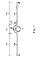
- FIG. 4 is a schematic cross-sectional view of the footboard 52 and the down frame 42 along line A-A in FIG. 1 .
- the top of the down frame 42 is positioned in a space S2 formed on the inside of the convex part 52C, as illustrated in FIG. 4 .
- the convex part 52C curves upward along the external peripheral shape of the down frame 42.
- the left flat plate 52L and the right flat plate 52R have an equal width W2.
- the width W2 is greater than the width W1 of the convex part 52C.
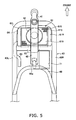
- FIG. 5 is a plan view of the vehicle body frame and the radiator 61 in a state in which the vehicle body cover has been removed.
- FIG. 6 is a perspective view of the vehicle body frame and the radiator 61 in a state in which the vehicle body cover has been removed.
- the radiator 61 includes a radiator core 610, a left tank 61 L, and a right tank 61 R, as illustrated in FIG. 5 .
- the left tank 61 L and the right tank 61 R each constitute a radiator tank in which cooling water is stored.
- the left tank 61 L is connected to the radiator core 610 on the left side of the radiator core 610.
- the right tank 61 R is connected to the radiator core 610 on the right side of the radiator core 610.
- the fan 62 is placed in the center of the radiator core 610.
- One ends of water passages 63, 64 are connected to the left tank 61 L.
- the other ends of the water passages 63, 64 are connected to the cylinder part 31 a of the engine 31. Cooling water heated in the cylinder part 31 a of the engine 31 is fed to the left tank 61 L via the water passage 63, and also to the right tank 61 R through the rear part of the radiator core 610.
- the cooling water fed to the right tank 61 R is fed again to the left tank 61 L through the front part of the radiator core 610, and is delivered to the cylinder part 31 a of the engine 31 via the water passage 64.
- the radiator core 610 includes cooling tubes 616 and cooling fins 615.
- the cooling tubes 616 are placed along the vehicle width direction and are arranged at fixed intervals in the vehicle longitudinal direction. Cooling water flows into the cooling tubes 616.
- the cooling fins 615 are provided adjacent to the cooling tubes 616 and in between the cooling tubes 616.
- the cooling fins 615 are formed by bending metal plates multiple times.
- the side frames 43 extend along the vehicle longitudinal direction through the left and right sides of the radiator 61 from a point in front of the front end of the radiator 61.
- the space between the left and right side frames 43L, 43R in the vehicle width direction substantially coincides with the width of the radiator 61.
- the water passages 63, 64 are partially placed below the left side frame 43L.
- the left and right side frames 43L, 43R are joined to the down frame 42 via a bracket 57.
- the bracket 57 is provided behind the fan 62 in order to avoid interfering with the fan 62.
- the distance between the front ends of the side frames 43 and the bracket 57 substantially coincides with the length of the radiator 61 in the longitudinal direction of the vehicle body.
- the battery 71 is placed between the right side frame 43R and the down frame 42.
- the water passages 63, 64 are partially placed between the left side frame 43L and the down frame 42.
- the center of the cross frame 48 and the rear end of the down frame 42 are connected by a link 48a.
- the cross frame 48 has a U shape curved to be convex toward the front.
- the cross frame 48 is formed into a shape such that the space enclosed by the cross frame 48 widens toward the rear in the vehicle width direction. Interference between the cross frame 48 and the engine 31 (the cylinder part 31a) is thereby avoided.
- the down frame 42 includes a bending portion 42a which is bent toward the rear, and a rear end extending rearward from the bending portion 42a, as illustrated in FIG. 6 .
- the radiator unit 60 (radiator 61, fan 62) is placed below the bending portion 42a.
- brackets 56 Connected to the bending portion 42a is a pair of left and right brackets 56 extending at a downward and forward incline from the bending portion 42a.
- the front ends of the side frames 43 are connected to the bottom ends of the brackets 56.
- the brackets 56 are disposed in front of the radiator 61. Therefore, when the vehicle rides up on a curb, the brackets 56 can protect the radiator 61.
- FIG. 6 illustrations of the bracket 57 and the battery 71 illustrated in FIG. 5 are omitted.
- FIG. 7 is a schematic cross-sectional view illustrating the detailed configuration of the radiator periphery.
- the radiator 61 has a main surface 611 that faces the flow of air F passing through the ventilation duct 90, as illustrated in FIG. 7 .
- the main surface 611 is positioned on the top surface of the radiator 61. Part of the main surface 611 is positioned farther forward in the vehicle body than a downward imaginary extension surface L1 of the front cover 51 that forms the rear wall of the ventilation duct 90.
- the main surface 611 is disposed so as to intersect the imaginary extension surface L1. Specifically, the main surface 611 is substantially orthogonal to the direction in which the air F flows through the ventilation duct 90.
- the extension direction of the imaginary extension surface L1 is substantially parallel to an axial line in the linear portion of the down frame 42 in a side view of the vehicle.
- the imaginary extension surface L1 may be defined by drawing a line substantially parallel to the axial line in the linear portion of the down frame 42 from the rearmost portion (outlet portion) of the ventilation duct in a side view of the vehicle.
- the footboard 52 extends toward the rear of the vehicle body from the rear part 51 a of the front cover 51.
- the radiator 61 has a bottom surface 612 provided on the opposite side of the main surface 611.
- the main surface 611 and the bottom surface 612 are surfaces over which air passes, and the main and bottom surfaces are both larger in surface area than the other surfaces of the radiator 61.
- the front opening 91 is positioned above the radiator 61 and the fan 62.
- the bottom and the left and right sides of the radiator 61 are covered by the lower cover 53.
- the lower cover 53 extends toward the rear of the vehicle body from a bottom part 511D of the inner fender 511, in a lower position than the footboard 52.
- a bottom opening 92 is formed in the lower cover 53, below the bottom surface 612 of the radiator 61.
- the inner fender 511 curves along the external peripheral shape of the front wheel 21. Specifically, a center part 511C of the inner fender 511 is positioned rearward of the top part 511U and the bottom part 511D. The center part 511C of the inner fender 511 is also positioned rearward of the left and right sides of the inner fender 511.
- a wind guard plate 95 (wind guard member) is placed above the rear end of the radiator 61.
- the wind guard plate 95 extends toward the footboard 52 from the rear side, respectively a rear portion, of the main surface 611.
- the wind guard plate 95 is disposed at an incline so as to intersect a plane including the main surface 611.
- FIG. 8 is a perspective view of the two-wheeled motor vehicle 10 as seen from below.
- the bottom opening 92 is formed into a quadrilateral shape so as to substantially coincide with the shape of the bottom surface 612 of the radiator core 610, as illustrated in FIG. 8 . Therefore, the surface area of the bottom opening 92 substantially coincides with the surface area of the bottom surface 612 of the radiator core 610.
- the air F having flowed into the front opening 91, then flows downward through the ventilation duct 90. Specifically, the air F flows downward along the down frame 42.
- the air F passing through the ventilation duct 90 is fed to the main surface 611 from a direction substantially orthogonal to the main surface 611.
- the air F passes through the radiator core 610 to be discharged downward from the bottom surface 612 of the radiator core 610.
- the front opening 91 functions as an air intake port
- the bottom opening 92 functions as an air discharge port.
- the fan 62 operates when the temperature of the cooling water has exceeded a specified value.
- the fan 62 blows air downward from above the radiator 61.
- the fan 62 creates a flow of air flowing from the main surface 611 toward the bottom surface 612.
- air F can be blown to the main surface 611 even when the two-wheeled motor vehicle 10 is not moving.
- the two-wheeled motor vehicle 10 stops moving while the fan 62 is not moving, air F heated through the radiator 61 flows upward through the ventilation duct 90, and the air is discharged from the front opening 91.
- the bottom opening 92 functions as an air intake port
- the front opening 91 functions as an air discharge port.
- the radiator 61 is placed lower than the footboard 52, and the front of the radiator 61 is covered by the inner fender 511. Part of the main surface 611 of the radiator 61 is positioned farther forward in the vehicle body than the downward imaginary extension surface L1 of the portion forming the rear wall of the ventilation duct 90 in the front cover 51. Therefore, air F passing through the ventilation duct 90 is efficiently fed to the main surface 611 of the radiator 61. Consequently, a coolant can be efficiently cooled in the radiator 61. Therefore, heat exchange can be efficiently performed in the radiator 61. Since the ventilation duct 90 is formed by the inside surface of the front cover 51, the front cover 51 can also be used to form the ventilation duct 90 without separately providing a special mechanism.
- the radiator 61 can be reduced in size by improving the cooling efficiency in the radiator 61. Therefore, the radiator 61 can be accommodated in a small space beneath the footboard 52 without dividing the radiator 61. The cost of the radiator 61 can also be reduced in comparison with dividing the radiator 61. Furthermore, air can be blown by the fan 62 to the radiator 61 even while the two-wheeled motor vehicle 10 is not moving. Therefore, the engine 31 can be prevented from reaching excessively high temperatures even while the two-wheeled motor vehicle 10 is not moving.
- the footboard 52 is shaped as a flat plate. Specifically, the widths W2 of the left flat plate 52L and the right flat plate 52R are both greater in the vehicle width direction than the width W1 of the convex part 52C. The rider's ease of riding can be enhanced by forming the footboard 52 into a substantially flat shape in this manner.
- the front opening 91 is positioned higher than the radiator 61. Air F taken in from the front opening 91 is thereby fed through the ventilation duct 90 to the main surface 611 of the radiator 61 from above, and air F can therefore be efficiently fed to the radiator 61, which has a substantially horizontal arrangement.
- the front opening 91 is positioned higher than the front wheel 21. Therefore, air F can be efficiently fed to the radiator 61 because the air F (traveling wind) from a point in front of the two-wheeled motor vehicle 10 is taken into the front opening 91 without being blocked by the front wheel 21.
- the flat plate-shaped radiator 61 has a substantially horizontal arrangement. Therefore, the height of the radiator 61 in the vertical direction of the vehicle body can be reduced in cases in which the radiator 61 is placed lower than the footboard 52. Therefore, the footboard 52 can be formed substantially flat even in cases in which the radiator 61 is placed below the footboard 52. It is also possible to ensure the minimum ground clearance needed in the lower cover 53 below the radiator 61.
- the main surface 611 of the radiator 61 is substantially orthogonal to the direction in which air F flows through the ventilation duct 90. Therefore, the air F can be efficiently fed to the main surface 611.
- the fan 62 for blowing air to the main surface 611 of the radiator 61 is placed above the main surface 611.
- the fan 62 is placed above the radiator 61. Therefore, the space between the radiator 61 and the footboard 52 can be increased in size in comparison with a case of placing the fan 62 below the radiator 61.
- the main surface 611 of the radiator 61 can thereby be more easily made orthogonal to the direction in which air F flows through the ventilation duct 90.
- the wind guard plate 95 placed below the footboard 52 extends toward the footboard 52 from the rear side of the main surface 611 of the radiator 61. Air F fed from above the main surface 611 can thereby be prevented from flowing toward the rear of the main surface 611, and the quantity of air F passing over the main surface 611 can be increased.
- the fuel tank 26 is placed below the seat 25, rather than the fuel tank 26 being placed below the footboard 52. Space for placing the radiator 61 and electrical components (battery 71) can thereby be ensured below the footboard 52.
- the left tank 61 L and the right tank 61 R are placed to the sides of the radiator core 610.
- the radiator core 610 can therefore be disposed farther forward than in cases in which these tanks are placed in front of and behind the radiator core 610.
- the air F passing through the ventilation duct 90 is thereby efficiently fed to the main surface 611 of the radiator 61.
- the radiator 61 To increase the cooling capacity of the radiator 61, consideration has been given to disposing the radiator 61 in a region of the two-wheeled motor vehicle 10 where air readily flows in.
- the radiator 61 could be disposed in an internal space in the top part 51 U of the front cover 51.
- a storage part 58 such as is described above could not be provided to the top part 51 U.
- the capacity of the storage part 58 would be reduced.
- the radiator 61 can be housed below the footboard 52 without reducing the cooling performance of the radiator 61. Therefore, the internal space in the top part 51 U can be used as a space for providing the storage part 58, and a large-capacity storage part 58 can be provided. The space in the top part 51 U can also be used as a space for disposing a lighting device.
- the radiator 61 can be housed below the footboard 52 without reducing the cooling performance of the radiator 61. Therefore, the size increase of the wheel base can be minimized even if the front wheel 21 has a large outside diameter. The size increase in the vehicle can thereby be minimized.
- part of the main surface 611 of the radiator 61 was positioned farther forward in the vehicle body than the imaginary extension surface L1, but the entire main surface 611 of the radiator 61 may also be positioned farther forward in the vehicle body than the imaginary extension surface L1.
- the bottom opening 92 is formed into a quadrilateral shape that substantially coincides with the shape of the bottom surface 612 of the radiator core 610, but the bottom opening 92 is not limited to a quadrilateral shape and may also be circular or another shape. Alternatively, a configuration having no bottom opening 92 is also possible.
- the widths W2 of the left flat plate 52L and the right flat plate 52R in the vehicle width direction are greater than the width W1 of the convex part 52C, but the widths W2 may also be less than the width W1.
- the footboard 52 can be formed to be entirely flat without providing a convex part 52C.
- the front opening 91 is positioned higher than the radiator 61 and the front wheel 21, but part of the front opening 91 may be positioned lower than the radiator 61 and the front wheel 21.
- the radiator 61 has a substantially horizontal arrangement, but the radiator 61 may also be arranged at an incline, respectively in a non-horizontal and non-vertical state.
- the inclination of the main surface 611 of the radiator 61 to a horizontal plane is less than 90°, preferably less than 60°, and in particular preferably less than 30°.
- the radiator 61 may be arranged at a forward and downward incline in a side view. In this case, the front end of the radiator 61 is positioned lower than the rear end. This type of incline makes it possible for the main surface 611 of the radiator 61 and the direction in which air F flows through the ventilation duct 90 to be made more orthogonal to each other.
- the wind guard plate 95 was placed below the footboard 52 and above the rear end of the radiator 61.
- the wind guard plate 95 may also be placed above the front end of the radiator 61.
- the air F fed from above the main surface 611 can thereby be prevented from flowing toward the front of the main surface 611, and the quantity of air F passing over the main surface 611 can be increased.
- a configuration having no wind guard plate 95 is also possible.
- the fan 62 was placed above the radiator 61, but the fan 62 may also be placed below the radiator 61. Alternatively, a configuration having no fan 62 is also possible. The fan 62 may also blow air downward from above the radiator 61. However, for the sake of inhibiting warm air from reaching the rider, it is preferred that the fan 62 blow air downward from above the radiator 61, as in the embodiment described above.
- the front wheel 21 and the rear wheel 22 have an outside diameter of 14 inches or greater, but the wheel diameter may also be less than 14 inches.
- a preferred embodiment of a saddle-riding vehicle has a front cover 51 provided with a front opening 91 that opens toward the front of the vehicle body.
- the front of a radiator 61 placed below a footboard 52 is covered by an inner fender 511, and part of a main surface 611 of the radiator 61 is positioned farther forward in the vehicle body than a downward imaginary extension surface L1 of a portion of the front cover 51 constituting a rear wall of a ventilation duct 90.
Landscapes
- Engineering & Computer Science (AREA)
- Mechanical Engineering (AREA)
- Automatic Cycles, And Cycles In General (AREA)
- Cooling, Air Intake And Gas Exhaust, And Fuel Tank Arrangements In Propulsion Units (AREA)
Abstract
Description
- The present invention relates to a saddle-riding vehicle wherein a radiator is placed underneath a footboard on which a rider's feet are rested.
- In saddle-riding vehicles such as two-wheeled motor vehicles, radiators are widely used for cooling a coolant that has absorbed the heat of an engine. The radiator has a main surface. The main surface is formed by a cooling tube through which the coolant flows and a cooling fin adjacent to the cooling tube. The radiator emits the heat of the coolant to a cooling draft flowing in from the main surface and passing through the radiator.
- This type of radiator is used in a saddle-riding vehicle having a footboard on which rest the rider's feet, or a so-called scooter-type two-wheeled motor vehicle. For example, in Japanese Utility Model Publication No.
S62-38471 Page 1,Fig. 4 ), a technique is known in which a flat plate-shaped radiator is placed underneath the footboard in a scooter-type two-wheeled motor vehicle. It is difficult to ensure space for the upright mounting of a radiator underneath the footboard. Therefore, the radiator is laid horizontally underneath the footboard. - However, in the aforesaid Japanese Utility Model Publication, the main surface is arranged facing downward, and the cooling draft flows toward the radiator from the front of the vehicle body. Therefore, much of the cooling draft does not flow orthogonal to the main surface or enter into the radiator from the main surface, but rather flows toward the rear of the vehicle body along the main surface. Therefore, this type of radiator has a problem in that heat exchange cannot be performed efficiently. The present invention was devised in view of such circumstances.
- It is an objective of the present invention to provide a saddle-riding vehicle wherein a coolant can be efficiently cooled in a radiator placed underneath a footboard.
- According to the present invention, said objective is solved by a saddle-riding vehicle comprising: a vehicle body and a driving source; a front cover part being provided with a front opening which opens toward a front of the vehicle body, said front cover part comprising a ventilation duct configured to pass air that has flowed in from the front opening toward a radiator configured to cool the driving source; a footboard part on which rider's feet can be rested, the footboard part extending toward a rear of the vehicle body from a rear part of the front cover part; and the radiator being placed lower than the footboard part, with a main surface of the radiator being oriented horizontally or inclined, wherein at least part of the main surface is positioned farther forward in the vehicle body than a downward imaginary extension surface of a portion of the front cover part constituting a rear wall of the ventilation duct.
- In such a saddle-riding vehicle, the radiator is placed lower than the footboard part. Preferably, the front of the radiator is covered by a wind guard cover. The main surface of the radiator is arranged in a horizontal or inclined orientation. At least part of the main surface of the radiator is positioned farther forward in the vehicle body than the downward imaginary extension surface of the portion of the front cover part constituting the rear wall of the ventilation duct provided to the front cover part. Therefore, air passing through the ventilation duct flows mostly orthogonal to the main surface of the radiator, and the air is fed efficiently into the radiator. Heat exchange can thereby be performed efficiently in the radiator.
- Preferably, a down frame extends downward from a steering head pipe, and the front cover part encloses a periphery of the down frame and, preferably, is separated from the down frame.
- Further, preferably a front wheel is attached to the vehicle body in front of the front cover part, and the front opening is positioned higher than the front wheel.
- Still further, preferably a side frame extends toward the rear of the vehicle body from a bottom part of the down frame and, preferably, the driving source is swingably attached to the side frame.
- According to a preferred embodiment, a bottom part of the front cover part constitutes the ventilation duct, and/or a front of the radiator is covered by a wind guard cover extending downward from a bottom edge of the front opening, and/or an air blower is configured to blow air to the radiator, the air blower being preferably placed in vertical alignment with the radiator.
- Preferably, the air blower is placed above the main surface of the radiator.
- Further, preferably the air blower is configured to blow air downward from above the radiator.
- According to another preferred embodiment, a lower cover part extends toward the rear of the vehicle body from a bottom part of the wind guard cover in a lower position than the footboard part, the main surface of the radiator represents a top surface of the radiator, wherein the radiator has a bottom surface provided on a side opposite the main surface, and at least a portion of the bottom surface and both sides of the radiator are preferably covered by the lower cover part, and, preferably, a bottom opening that opens downward is provided in a portion of the lower cover part that faces the bottom surface.
- Preferably, the footboard part is shaped as a flat plate.
- Further, preferably the footboard part comprises a pair of flat plate parts and a convex part preferably formed into an upward convex shape, the convex part extends in longitudinal direction of the vehicle body between the pair of flat plate parts, a down frame preferably extends toward the rear of the vehicle body along a space provided on the inside of the convex part, and widths of the pair of flat plate parts in vehicle width direction are preferably greater than a width of the convex part.
- Still further, preferably the front opening is positioned higher than the radiator.
- Yet further still, preferably the main surface of the radiator is substantially orthogonal to a direction in which air flows through the ventilation duct.
- Preferably, a wind guard member is placed below the footboard part and, preferably, extends toward the footboard part from a rear portion of the main surface of the radiator.
- Further, preferably a seat on which a rider can sit is provided and a fuel tank configured to store fuel to be supplied to the driving source is placed below the seat.
- Still further, preferably the radiator has a radiator core through which cooling water flows and at least one radiator tank configured to store the cooling water, and the radiator tank is preferably placed on a side of the radiator core.
- According to the above, it is possible to provide a saddle-riding vehicle wherein heat exchange can be efficiently performed in a radiator placed below a footboard.
- In the following, the present invention is explained in greater detail by means of embodiments thereof in conjunction with the accompanying drawings, wherein:
- FIG. 1
- is a left side view of the two-wheeled motor vehicle according to an embodiment;
- FIG. 2
- is a front view of the two-wheeled motor vehicle according to an embodiment;
- FIG. 3
- is a perspective view of the footboard according to an embodiment;
- FIG. 4
- is a schematic cross-sectional view of the footboard and the down frame along line A-A in
FIG. 1 ; - FIG. 5
- is a plan view of the vehicle body frame and the radiator in a state in which the vehicle body cover has been removed;
- FIG. 6
- is a perspective view of the vehicle body frame and the radiator in a state in which the vehicle body cover has been removed;
- FIG. 7
- is a schematic cross-sectional view illustrating the detailed configuration of the radiator periphery; and
- FIG. 8
- is a perspective view of the two-wheeled motor vehicle according to an embodiment.
- The following reference signs are used in the figures:
- F
- Air
- S1, S2
- Spaces
- W1, W2
- Widths
- L1
- Imaginary extension surface
- 10
- Two-wheeled motor vehicle
- 21
- Front wheel
- 22
- Rear wheel
- 23
- Front fender
- 24
- Front fork
- 25
- Seat
- 26
- Fuel tank
- 30
- Engine unit
- 31
- Engine
- 31a
- Cylinder part
- 31b
- Crankcase
- 32
- Transmission unit
- 33
- Cushion unit
- 41
- Steering head pipe
- 42
- Down frame
- 42a
- Bending portion
- 43, 43L, 43R
- Side frames
- 45
- Pivot part
- 48
- Cross frame
- 48a
- Link
- 51
- Front cover
- 51a
- Rear part
- 51D
- Bottom part
- 51U
- Top part
- 52
- Footboard
- 52C
- Convex part
- 52L
- Left flat plate
- 52R
- Right flat plate
- 53
- Lower cover
- 56, 57
- Brackets
- 60
- Radiator unit
- 61
- Radiator
- 61L
- Left tank
- 61R
- Right tank
- 62
- Fan
- 63, 64
- Water passages
- 71
- Battery
- 90
- Ventilation duct
- 91
- Front opening
- 92
- Bottom opening
- 95
- Wind guard plate
- 511
- Inner fender
- 511D
- Bottom part
- 512
- Rising part
- 512C
- Convex part
- 512L, 512R
- Concave parts
- 610
- Radiator core
- 611
- Main surface
- 612
- Bottom surface
- 615
- Cooling fin
- 616
- Cooling tube
- Next, the configuration of a saddle-riding vehicle according to an embodiment will be described with reference to the drawings. Specifically, given below are descriptions of (1) the overall schematic configuration of a saddle-riding vehicle, (2) the configuration of a front cover, a lower cover, and a footboard, (3) the configuration of a vehicle body frame and a radiator, (4) the detailed configuration of the periphery of the radiator, (5) the operation and effects, and (6) other embodiments.
- In the following description of the drawings, identical or similar components are denoted by identical or similar numerical symbols. It should be noted that the drawings merely schematic representations whose dimensional ratios and other features are different from the actual ratios and features.
- Therefore, the specific dimensions and other features should be determined with consideration of the following descriptions. It is apparent that different drawings also include components having mutually different dimensional relationships and ratios.
-
FIG. 1 is a left side view of a two-wheeledmotor vehicle 10 as a saddle-riding vehicle according to the present embodiment. - A footrest space S1 is formed in the two-wheeled
motor vehicle 10 in front of aseat 25 on which a rider sits, as illustrated inFIG. 1 . A footboard 52 (footboard part) is placed below the footrest space S1. Specifically, the two-wheeledmotor vehicle 10 is a so-called scooter-type two-wheeled motor vehicle. - The
footboard 52 on which the rider places his/her feet is provided at the bottom of the vehicle. Afuel tank 26 for storing fuel supplied to an engine (driving source) 31 is placed below theseat 25. Thefuel tank 26 is placed above theengine 31 on the inside of arear cover 54. - The two-wheeled
motor vehicle 10 includes afront wheel 21 and arear wheel 22, and therear wheel 22 is driven by a drive force produced by theengine 31. Thefront wheel 21 and therear wheel 22 have outside diameters of 14 inches or greater. Thefront wheel 21 is rotatably supported by a pair of left and rightfront forks 24. Afront fender 23 for covering the top of thefront wheel 21 is provided above thefront wheel 21. Thefront fender 23 is attached to thefront forks 24. - The
front forks 24 are rotatably supported by asteering head pipe 41. A columnar downframe 42 is joined to thesteering head pipe 41. The downframe 42 extends downward from the steeringhead pipe 41 and bends rearward. - A pair of left and right side frames 43 is joined to the
down frame 42. The side frames 43 extend at an upward and rearward incline from below thedown frame 42 through the left and right sides of theengine 31. The pair of left and right side frames 43 are joined by across frame 48. Thecross frame 48 supports thefuel tank 26. - The side frames 43 include a
pivot part 45 for swingably supporting the top part of theengine 31. Theengine 31 is a four stroke engine that includes acylinder part 31 a and acrankcase 31 b connected to thecylinder part 31 a. - A
transmission unit 32 for transmitting drive force to therear wheel 22 is provided to the left of thecrankcase 31 b. Joined to the rear end of thetransmission unit 32 is a bottom end of acushion unit 33 for absorbing impact received by therear wheel 22. The top end of thecushion unit 33 is joined to the side frames 43. - An
engine unit 30 is configured from theengine 31 and thetransmission unit 32. Theengine unit 30 is arranged so that its cylinder shaft extends substantially along the longitudinal direction of the vehicle. Theengine unit 30 is a swinging engine unit capable of swinging vertically about thepivot part 45 as a swinging center. - A front cover 51 (front cover part) is placed in front of the footrest space S1. The
front cover 51 encloses the periphery of thedown frame 42 in a state in which the cover is separated from thedown frame 42. In other words, thefront cover 51 is formed into a hollow shape. - The
top part 51 U of thefront cover 51 encloses the periphery of thedown frame 42 and the periphery of thesteering head pipe 41. The rear surface of thetop part 51 U is provided with astorage part 58 for storing beverage containers or small articles. Thestorage part 58 has a shape concaved forward from the rear surface of thetop part 51 U. Abottom part 51 D of thefront cover 51 is joined to thefootboard 52. Specifically, thefootboard 52 is joined to arear part 51 a (seeFIG. 3 ) of thefront cover 51. - The
footboard 52 is formed to be substantially flat. Thefootboard 52 covers the top of thedown frame 42 and the tops of the side frames 43. - A
radiator unit 60 and abattery 71 are placed below thefootboard 52. Theradiator unit 60 and thebattery 71 are placed between the pair of left and right side frames 43. - The
radiator unit 60 includes a radiator (e.g. a single radiator) 61 and a fan 62 (air blower). Theradiator 61 has a flat plate shape and is arranged to be substantially horizontal. Cooling water flowing through the interior of theengine 31 is fed into theradiator 61. Heat from the cooling water is taken by the air passing through theradiator 61, and theengine 31 is cooled. Accordingly, theradiator 61 is configured to cool theengine 31. - The
fan 62 is placed above theradiator 61. Thefan 62 has an electric motor (not shown), and air is blown into theradiator 61 by the driving of the electric motor. A lower cover 53 (lower cover part) is disposed below and to the sides of theradiator unit 60 and thebattery 71. -
FIG. 2 is a front view of the two-wheeledmotor vehicle 10. - The
front cover 51 includes aninner fender 511 for covering the rear of thefront fender 23 and the rears of thefront forks 24, as illustrated inFIG. 2 . Afront opening 91 which opens to the front of the vehicle body is formed in theinner fender 511. In the present embodiment, theinner fender 511 extends downward from the bottom edge of thefront opening 91, constituting a wind guard cover for covering the front of theradiator 61. - The
front opening 91 is formed along the vehicle width direction in a higher position than thefront fender 23. Thebottom part 51 D of thefront cover 51 is provided with aventilation duct 90 for passing the air that has flowed in from thefront opening 91. In other words, the inside surface of thehollow front cover 51 is also used to form theventilation duct 90. In general, thefront cover 51 comprises theventilation duct 90, which is configured to pass air that has flowed in from thefront opening 91 toward theaforesaid radiator 61. -
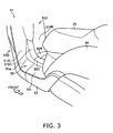
FIG. 3 is a perspective view of thefootboard 52. - The
footboard 52 is configured from a leftflat plate 52L, a rightflat plate 52R, and aconvex part 52C, as illustrated inFIG. 3 . - The left
flat plate 52L and the rightflat plate 52R are shaped as flat plates. Theconvex part 52C extends along the longitudinal direction of the vehicle body between the leftflat plate 52L and the rightflat plate 52R. Theconvex part 52C is formed into a convex shape protruding upward. - The
front cover 51 includes a risingpart 512 which rises upward from the front end of thefootboard 52. The inside surface of the risingpart 512 constitutes the rear surface of theventilation duct 90. - The rising
part 512 includes a convex part 512C andconcave parts down frame 42. The convex part 512C curves rearward along the external peripheral shape of thedown frame 42. Theconcave parts concave parts -
FIG. 4 is a schematic cross-sectional view of thefootboard 52 and thedown frame 42 along line A-A inFIG. 1 . - The top of the
down frame 42 is positioned in a space S2 formed on the inside of theconvex part 52C, as illustrated inFIG. 4 . Theconvex part 52C curves upward along the external peripheral shape of thedown frame 42. - The left
flat plate 52L and the rightflat plate 52R have an equal width W2. The width W2 is greater than the width W1 of theconvex part 52C. -
FIG. 5 is a plan view of the vehicle body frame and theradiator 61 in a state in which the vehicle body cover has been removed.FIG. 6 is a perspective view of the vehicle body frame and theradiator 61 in a state in which the vehicle body cover has been removed. - In this two-wheeled
motor vehicle 10, a plurality of radiators formed separately is not provided, but only oneradiator 61 is provided. Theradiator 61 includes aradiator core 610, aleft tank 61 L, and aright tank 61 R, as illustrated inFIG. 5 . Theleft tank 61 L and theright tank 61 R each constitute a radiator tank in which cooling water is stored. Theleft tank 61 L is connected to theradiator core 610 on the left side of theradiator core 610. Theright tank 61 R is connected to theradiator core 610 on the right side of theradiator core 610. Thefan 62 is placed in the center of theradiator core 610. - One ends of
water passages left tank 61 L. The other ends of thewater passages cylinder part 31 a of theengine 31. Cooling water heated in thecylinder part 31 a of theengine 31 is fed to theleft tank 61 L via thewater passage 63, and also to theright tank 61 R through the rear part of theradiator core 610. The cooling water fed to theright tank 61 R is fed again to theleft tank 61 L through the front part of theradiator core 610, and is delivered to thecylinder part 31 a of theengine 31 via thewater passage 64. - The
radiator core 610 includes coolingtubes 616 and coolingfins 615. The coolingtubes 616 are placed along the vehicle width direction and are arranged at fixed intervals in the vehicle longitudinal direction. Cooling water flows into the coolingtubes 616. The coolingfins 615 are provided adjacent to thecooling tubes 616 and in between the coolingtubes 616. The coolingfins 615 are formed by bending metal plates multiple times. - The side frames 43 extend along the vehicle longitudinal direction through the left and right sides of the
radiator 61 from a point in front of the front end of theradiator 61. The space between the left and right side frames 43L, 43R in the vehicle width direction substantially coincides with the width of theradiator 61. Thewater passages left side frame 43L. - The left and right side frames 43L, 43R are joined to the
down frame 42 via abracket 57. Thebracket 57 is provided behind thefan 62 in order to avoid interfering with thefan 62. The distance between the front ends of the side frames 43 and thebracket 57 substantially coincides with the length of theradiator 61 in the longitudinal direction of the vehicle body. - The
battery 71 is placed between theright side frame 43R and thedown frame 42. Thewater passages left side frame 43L and thedown frame 42. - The center of the
cross frame 48 and the rear end of thedown frame 42 are connected by alink 48a. Thecross frame 48 has a U shape curved to be convex toward the front. Thecross frame 48 is formed into a shape such that the space enclosed by thecross frame 48 widens toward the rear in the vehicle width direction. Interference between thecross frame 48 and the engine 31 (thecylinder part 31a) is thereby avoided. - The down
frame 42 includes a bendingportion 42a which is bent toward the rear, and a rear end extending rearward from the bendingportion 42a, as illustrated inFIG. 6 . The radiator unit 60 (radiator 61, fan 62) is placed below the bendingportion 42a. - Connected to the bending
portion 42a is a pair of left andright brackets 56 extending at a downward and forward incline from the bendingportion 42a. The front ends of the side frames 43 are connected to the bottom ends of thebrackets 56. Thebrackets 56 are disposed in front of theradiator 61. Therefore, when the vehicle rides up on a curb, thebrackets 56 can protect theradiator 61. InFIG. 6 , illustrations of thebracket 57 and thebattery 71 illustrated inFIG. 5 are omitted. -
FIG. 7 is a schematic cross-sectional view illustrating the detailed configuration of the radiator periphery. - The
radiator 61 has amain surface 611 that faces the flow of air F passing through theventilation duct 90, as illustrated inFIG. 7 . Themain surface 611 is positioned on the top surface of theradiator 61. Part of themain surface 611 is positioned farther forward in the vehicle body than a downward imaginary extension surface L1 of thefront cover 51 that forms the rear wall of theventilation duct 90. Themain surface 611 is disposed so as to intersect the imaginary extension surface L1. Specifically, themain surface 611 is substantially orthogonal to the direction in which the air F flows through theventilation duct 90. - The extension direction of the imaginary extension surface L1 is substantially parallel to an axial line in the linear portion of the
down frame 42 in a side view of the vehicle. In cases in which "the front cover part forming the rear wall of the ventilation duct" cannot be recognized as a surface, the imaginary extension surface L1 may be defined by drawing a line substantially parallel to the axial line in the linear portion of thedown frame 42 from the rearmost portion (outlet portion) of the ventilation duct in a side view of the vehicle. - The
footboard 52 extends toward the rear of the vehicle body from therear part 51 a of thefront cover 51. - The
radiator 61 has abottom surface 612 provided on the opposite side of themain surface 611. Themain surface 611 and thebottom surface 612 are surfaces over which air passes, and the main and bottom surfaces are both larger in surface area than the other surfaces of theradiator 61. Thefront opening 91 is positioned above theradiator 61 and thefan 62. - The bottom and the left and right sides of the
radiator 61 are covered by thelower cover 53. Specifically, thelower cover 53 extends toward the rear of the vehicle body from abottom part 511D of theinner fender 511, in a lower position than thefootboard 52. Abottom opening 92 is formed in thelower cover 53, below thebottom surface 612 of theradiator 61. - The
inner fender 511 curves along the external peripheral shape of thefront wheel 21. Specifically, acenter part 511C of theinner fender 511 is positioned rearward of thetop part 511U and thebottom part 511D. Thecenter part 511C of theinner fender 511 is also positioned rearward of the left and right sides of theinner fender 511. - Below the
footboard 52, a wind guard plate 95 (wind guard member) is placed above the rear end of theradiator 61. Thewind guard plate 95 extends toward thefootboard 52 from the rear side, respectively a rear portion, of themain surface 611. Thewind guard plate 95 is disposed at an incline so as to intersect a plane including themain surface 611. -
FIG. 8 is a perspective view of the two-wheeledmotor vehicle 10 as seen from below. - The
bottom opening 92 is formed into a quadrilateral shape so as to substantially coincide with the shape of thebottom surface 612 of theradiator core 610, as illustrated inFIG. 8 . Therefore, the surface area of thebottom opening 92 substantially coincides with the surface area of thebottom surface 612 of theradiator core 610. - Next, the flow of air F fed to the
radiator 61 will be described usingFIG. 7 . When the two-wheeledmotor vehicle 10 is traveling, a traveling wind (air F) from the front side of thefront opening 91 and a traveling wind (air F) flowing over the surface of theinner fender 511 both flow into thefront opening 91. - The air F, having flowed into the
front opening 91, then flows downward through theventilation duct 90. Specifically, the air F flows downward along thedown frame 42. - The air F passing through the
ventilation duct 90 is fed to themain surface 611 from a direction substantially orthogonal to themain surface 611. The air F passes through theradiator core 610 to be discharged downward from thebottom surface 612 of theradiator core 610. Thus, thefront opening 91 functions as an air intake port, and thebottom opening 92 functions as an air discharge port. - The
fan 62 operates when the temperature of the cooling water has exceeded a specified value. Thefan 62 blows air downward from above theradiator 61. In other words, thefan 62 creates a flow of air flowing from themain surface 611 toward thebottom surface 612. When thefan 62 is operating, air F can be blown to themain surface 611 even when the two-wheeledmotor vehicle 10 is not moving. - When the two-wheeled
motor vehicle 10 stops moving while thefan 62 is not moving, air F heated through theradiator 61 flows upward through theventilation duct 90, and the air is discharged from thefront opening 91. In this case, the bottom opening 92 functions as an air intake port, and thefront opening 91 functions as an air discharge port. - In the two-wheeled
motor vehicle 10 according to the present embodiment, theradiator 61 is placed lower than thefootboard 52, and the front of theradiator 61 is covered by theinner fender 511. Part of themain surface 611 of theradiator 61 is positioned farther forward in the vehicle body than the downward imaginary extension surface L1 of the portion forming the rear wall of theventilation duct 90 in thefront cover 51. Therefore, air F passing through theventilation duct 90 is efficiently fed to themain surface 611 of theradiator 61. Consequently, a coolant can be efficiently cooled in theradiator 61. Therefore, heat exchange can be efficiently performed in theradiator 61. Since theventilation duct 90 is formed by the inside surface of thefront cover 51, thefront cover 51 can also be used to form theventilation duct 90 without separately providing a special mechanism. - The
radiator 61 can be reduced in size by improving the cooling efficiency in theradiator 61. Therefore, theradiator 61 can be accommodated in a small space beneath thefootboard 52 without dividing theradiator 61. The cost of theradiator 61 can also be reduced in comparison with dividing theradiator 61. Furthermore, air can be blown by thefan 62 to theradiator 61 even while the two-wheeledmotor vehicle 10 is not moving. Therefore, theengine 31 can be prevented from reaching excessively high temperatures even while the two-wheeledmotor vehicle 10 is not moving. - In the two-wheeled
motor vehicle 10 according to the present embodiment, the portion in thelower cover 53 that faces thebottom surface 612 of theradiator 61 is provided with abottom opening 92 opening downwardly. Since air F heated through theradiator 61 is discharged downward via thebottom opening 92, the heated air F can be prevented from being emitted toward theengine 31 and the rider. - In the two-wheeled
motor vehicle 10 according to the present embodiment, thefootboard 52 is shaped as a flat plate. Specifically, the widths W2 of the leftflat plate 52L and the rightflat plate 52R are both greater in the vehicle width direction than the width W1 of theconvex part 52C. The rider's ease of riding can be enhanced by forming thefootboard 52 into a substantially flat shape in this manner. - In the two-wheeled
motor vehicle 10 according to the present embodiment, thefront opening 91 is positioned higher than theradiator 61. Air F taken in from thefront opening 91 is thereby fed through theventilation duct 90 to themain surface 611 of theradiator 61 from above, and air F can therefore be efficiently fed to theradiator 61, which has a substantially horizontal arrangement. - In the two-wheeled
motor vehicle 10 according to the present embodiment, thefront opening 91 is positioned higher than thefront wheel 21. Therefore, air F can be efficiently fed to theradiator 61 because the air F (traveling wind) from a point in front of the two-wheeledmotor vehicle 10 is taken into thefront opening 91 without being blocked by thefront wheel 21. - In the two-wheeled
motor vehicle 10 according to the present embodiment, the flat plate-shapedradiator 61 has a substantially horizontal arrangement. Therefore, the height of theradiator 61 in the vertical direction of the vehicle body can be reduced in cases in which theradiator 61 is placed lower than thefootboard 52. Therefore, thefootboard 52 can be formed substantially flat even in cases in which theradiator 61 is placed below thefootboard 52. It is also possible to ensure the minimum ground clearance needed in thelower cover 53 below theradiator 61. - In the two-wheeled
motor vehicle 10 according to the present embodiment, themain surface 611 of theradiator 61 is substantially orthogonal to the direction in which air F flows through theventilation duct 90. Therefore, the air F can be efficiently fed to themain surface 611. - In the two-wheeled
motor vehicle 10 according to the present embodiment, thefan 62 for blowing air to themain surface 611 of theradiator 61 is placed above themain surface 611. In other words, thefan 62 is placed above theradiator 61. Therefore, the space between theradiator 61 and thefootboard 52 can be increased in size in comparison with a case of placing thefan 62 below theradiator 61. Themain surface 611 of theradiator 61 can thereby be more easily made orthogonal to the direction in which air F flows through theventilation duct 90. - In the two-wheeled
motor vehicle 10 according to the present embodiment, thewind guard plate 95 placed below thefootboard 52 extends toward thefootboard 52 from the rear side of themain surface 611 of theradiator 61. Air F fed from above themain surface 611 can thereby be prevented from flowing toward the rear of themain surface 611, and the quantity of air F passing over themain surface 611 can be increased. - In the two-wheeled
motor vehicle 10 according to the present embodiment, thefuel tank 26 is placed below theseat 25, rather than thefuel tank 26 being placed below thefootboard 52. Space for placing theradiator 61 and electrical components (battery 71) can thereby be ensured below thefootboard 52. - In the two-wheeled
motor vehicle 10 according to the present embodiment, theleft tank 61 L and theright tank 61 R are placed to the sides of theradiator core 610. Theradiator core 610 can therefore be disposed farther forward than in cases in which these tanks are placed in front of and behind theradiator core 610. The air F passing through theventilation duct 90 is thereby efficiently fed to themain surface 611 of theradiator 61. - To increase the cooling capacity of the
radiator 61, consideration has been given to disposing theradiator 61 in a region of the two-wheeledmotor vehicle 10 where air readily flows in. For example, theradiator 61 could be disposed in an internal space in thetop part 51 U of thefront cover 51. However, if theradiator 61 were to be disposed in the internal space in thetop part 51 U, astorage part 58 such as is described above could not be provided to thetop part 51 U. Alternatively, the capacity of thestorage part 58 would be reduced. - In view of this, in the two-wheeled
motor vehicle 10 according to the present embodiment, theradiator 61 can be housed below thefootboard 52 without reducing the cooling performance of theradiator 61. Therefore, the internal space in thetop part 51 U can be used as a space for providing thestorage part 58, and a large-capacity storage part 58 can be provided. The space in thetop part 51 U can also be used as a space for disposing a lighting device. - Consideration has also been given to disposing the
radiator 61 in thebottom part 51 D of thefront cover 51 in order to increase the cooling capacity of theradiator 61. However, the space in thebottom part 51 D of thefront cover 51 positioned behind thefront wheel 21 would be smaller in the case of afront wheel 21 having a large outside diameter. Therefore, the wheel base would have to be larger in order to place theradiator 61 in thebottom part 51 D. In this case, the vehicle would increase in size. - In view of this, in the two-wheeled
motor vehicle 10 according to the present embodiment, theradiator 61 can be housed below thefootboard 52 without reducing the cooling performance of theradiator 61. Therefore, the size increase of the wheel base can be minimized even if thefront wheel 21 has a large outside diameter. The size increase in the vehicle can thereby be minimized. - The present teaching was described above using an embodiment, but the statements and drawings constituting a part of this disclosure should not be interpreted as limiting the teaching. Various alternative embodiments, examples, and applicable techniques will be apparent to those skilled in the art from this disclosure.
- In the embodiment, part of the
main surface 611 of theradiator 61 was positioned farther forward in the vehicle body than the imaginary extension surface L1, but the entiremain surface 611 of theradiator 61 may also be positioned farther forward in the vehicle body than the imaginary extension surface L1. - In the embodiment described above, the
bottom opening 92 is formed into a quadrilateral shape that substantially coincides with the shape of thebottom surface 612 of theradiator core 610, but thebottom opening 92 is not limited to a quadrilateral shape and may also be circular or another shape. Alternatively, a configuration having nobottom opening 92 is also possible. - Furthermore, in the embodiment described above, the widths W2 of the left
flat plate 52L and the rightflat plate 52R in the vehicle width direction are greater than the width W1 of theconvex part 52C, but the widths W2 may also be less than the width W1. Alternatively, thefootboard 52 can be formed to be entirely flat without providing aconvex part 52C. - In the embodiment described above, the
front opening 91 is positioned higher than theradiator 61 and thefront wheel 21, but part of thefront opening 91 may be positioned lower than theradiator 61 and thefront wheel 21. - In the embodiment described above, the
radiator 61 has a substantially horizontal arrangement, but theradiator 61 may also be arranged at an incline, respectively in a non-horizontal and non-vertical state. The inclination of themain surface 611 of theradiator 61 to a horizontal plane is less than 90°, preferably less than 60°, and in particular preferably less than 30°. For example, theradiator 61 may be arranged at a forward and downward incline in a side view. In this case, the front end of theradiator 61 is positioned lower than the rear end. This type of incline makes it possible for themain surface 611 of theradiator 61 and the direction in which air F flows through theventilation duct 90 to be made more orthogonal to each other. - In the embodiment described above, the
wind guard plate 95 was placed below thefootboard 52 and above the rear end of theradiator 61. However, thewind guard plate 95 may also be placed above the front end of theradiator 61. The air F fed from above themain surface 611 can thereby be prevented from flowing toward the front of themain surface 611, and the quantity of air F passing over themain surface 611 can be increased. A configuration having nowind guard plate 95 is also possible. - In the embodiment described above, the
fan 62 was placed above theradiator 61, but thefan 62 may also be placed below theradiator 61. Alternatively, a configuration having nofan 62 is also possible. Thefan 62 may also blow air downward from above theradiator 61. However, for the sake of inhibiting warm air from reaching the rider, it is preferred that thefan 62 blow air downward from above theradiator 61, as in the embodiment described above. - In the embodiment described above, the
front wheel 21 and therear wheel 22 have an outside diameter of 14 inches or greater, but the wheel diameter may also be less than 14 inches. - In general, the teaching above cannot only be applied to motorcycles, respectively scooter-type vehicles, but to all kinds of saddle-riding vehicles including all-terrain-vehicles, such as quads.
- In order to provide a saddle-riding vehicle wherein heat exchange can be efficiently performed in a radiator placed lower than a footboard, a preferred embodiment of a saddle-riding vehicle has a
front cover 51 provided with afront opening 91 that opens toward the front of the vehicle body. The front of aradiator 61 placed below afootboard 52 is covered by aninner fender 511, and part of amain surface 611 of theradiator 61 is positioned farther forward in the vehicle body than a downward imaginary extension surface L1 of a portion of thefront cover 51 constituting a rear wall of aventilation duct 90.
Claims (15)
- Saddle-riding vehicle comprising:a vehicle body and a driving source (31);a front cover part (51) being provided with a front opening (91) which opens toward a front of the vehicle body, said front cover part (51) comprising a ventilation duct (90) configured to pass air that has flowed in from the front opening (91) toward a radiator (61) configured to cool the driving source (31);a footboard part (52) on which rider's feet can be rested, the footboard part (52) extending toward a rear of the vehicle body from a rear part (51 a) of the front cover part (51); andthe radiator (61) being placed lower than the footboard part (52), with a main surface (611) of the radiator (61) being oriented horizontally or inclined,wherein at least part of the main surface (611) is positioned farther forward in the vehicle body than a downward imaginary extension surface (L1 ) of a portion of the front cover part (51) constituting a rear wall of the ventilation duct (90).
- Saddle-riding vehicle according to claim 1, wherein a down frame (42) extends downward from a steering head pipe (41), and the front cover part (51) encloses a periphery of the down frame (42) and, preferably, is separated from the down frame (42).
- Saddle-riding vehicle according to claim 1 or 2, wherein a front wheel (21) is attached to the vehicle body in front of the front cover part (51), and the front opening (91) is positioned higher than the front wheel (21).
- Saddle-riding vehicle according to claim 2 or 3, wherein a side frame (43) extends toward the rear of the vehicle body from a bottom part of the down frame (42) and, preferably, the driving source (31) is swingably attached to the side frame (43).
- Saddle-riding vehicle according to one of claims 1 to 4, wherein a bottom part (51D,511D) of the front cover part (51) constitutes the ventilation duct (90), and/or a front of the radiator (61) is covered by a wind guard cover extending downward from a bottom edge of the front opening (91), and/or an air blower (62) is configured to blow air to the radiator (61), the air blower (62) being preferably placed in vertical alignment with the radiator (61).
- Saddle-riding vehicle according to claim 5, wherein the air blower (62) is placed above the main surface (611) of the radiator (61).
- Saddle-riding vehicle according to claim 5 or 6, wherein the air blower (62) is configured to blow air downward from above the radiator (61).
- Saddle-riding vehicle according to one of claims 5 to 7, wherein a lower cover part (53) extends toward the rear of the vehicle body from a bottom part of the wind guard cover in a lower position than the footboard part (52), the main surface (611) of the radiator (61) represents a top surface of the radiator (61), wherein the radiator (61) has a bottom surface (612) provided on a side opposite the main surface (611), and at least a portion of the bottom surface (612) and both sides of the radiator (61) are preferably covered by the lower cover part (53), and, preferably, a bottom opening (92) that opens downward is provided in a portion of the lower cover part (53) that faces the bottom surface (612).
- Saddle-riding vehicle according to one of claims 1 to 8, wherein the footboard part (52) is shaped as a flat plate.
- Saddle-riding vehicle according to one of claims 1 to 9, wherein the footboard part (52) comprises a pair of flat plate parts (52L,52R) and a convex part (52C) preferably formed into an upward convex shape, the convex part (52C) extends in longitudinal direction of the vehicle body between the pair of flat plate parts (52L,52R), a down frame (42) preferably extends toward the rear of the vehicle body along a space provided on the inside of the convex part (52C), and widths (W2) of the pair of flat plate parts (52L,52R) in vehicle width direction are preferably greater than a width (W1) of the convex part (52C).
- Saddle-riding vehicle according to one of claims 1 to 10, wherein the front opening (91) is positioned higher than the radiator (61).
- Saddle-riding vehicle according to one of claims 1 to 11, wherein the main surface (611) of the radiator (61) is substantially orthogonal to a direction in which air flows through the ventilation duct (90).
- Saddle-riding vehicle according to one of claims 1 to 12, wherein a wind guard member (95) is placed below the footboard part (52) and, preferably, extends toward the footboard part (52) from a rear portion of the main surface (611) of the radiator (61).
- Saddle-riding vehicle according to one of claims 1 to 13, wherein a seat (25) on which a rider can sit is provided and a fuel tank (26) configured to store fuel to be supplied to the driving source (31) is placed below the seat (25).
- Saddle-riding vehicle according to one of claims 1 to 14, wherein the radiator (61) has a radiator core (610) through which cooling water flows and at least one radiator tank (61 L,61 R) configured to store the cooling water, and the radiator tank (61 L,61 R) is preferably placed on a side of the radiator core (610).
Applications Claiming Priority (1)
| Application Number | Priority Date | Filing Date | Title |
|---|---|---|---|
| JP2008335002 | 2008-12-26 |
Publications (3)
| Publication Number | Publication Date |
|---|---|
| EP2202138A2 true EP2202138A2 (en) | 2010-06-30 |
| EP2202138A3 EP2202138A3 (en) | 2012-05-23 |
| EP2202138B1 EP2202138B1 (en) | 2013-04-10 |
Family
ID=42102689
Family Applications (1)
| Application Number | Title | Priority Date | Filing Date |
|---|---|---|---|
| EP09014755.4A Not-in-force EP2202138B1 (en) | 2008-12-26 | 2009-11-26 | Saddle-riding vehicle |
Country Status (3)
| Country | Link |
|---|---|
| EP (1) | EP2202138B1 (en) |
| ES (1) | ES2404072T3 (en) |
| TW (1) | TWI395686B (en) |
Cited By (2)
| Publication number | Priority date | Publication date | Assignee | Title |
|---|---|---|---|---|
| WO2015067431A1 (en) * | 2013-11-11 | 2015-05-14 | Bayerische Motoren Werke Aktiengesellschaft | Multi-functional footboard support of a motor scooter |
| CN105501342A (en) * | 2014-10-10 | 2016-04-20 | 本田技研工业株式会社 | Saddle-riding type vehicle |
Citations (2)
| Publication number | Priority date | Publication date | Assignee | Title |
|---|---|---|---|---|
| JPS6238471U (en) | 1985-08-24 | 1987-03-07 | ||
| EP0960808A2 (en) | 1998-05-29 | 1999-12-01 | Yamaha Hatsudoki Kabushiki Kaisha | Drive system for motorcycles |
Family Cites Families (4)
| Publication number | Priority date | Publication date | Assignee | Title |
|---|---|---|---|---|
| JPH08127377A (en) * | 1994-10-31 | 1996-05-21 | Suzuki Motor Corp | Radiator arrangement structure of scooter type vehicle |
| JP2003019992A (en) * | 2001-07-09 | 2003-01-21 | Yamaha Motor Co Ltd | Scooter-type motorcycle cooling system |
| TWI355454B (en) * | 2005-09-30 | 2012-01-01 | Honda Motor Co Ltd | Vehicular cooling system |
| JP2008196355A (en) * | 2007-02-09 | 2008-08-28 | Yamaha Motor Co Ltd | Saddle riding vehicle |
-
2009
- 2009-11-26 ES ES09014755T patent/ES2404072T3/en active Active
- 2009-11-26 EP EP09014755.4A patent/EP2202138B1/en not_active Not-in-force
- 2009-12-03 TW TW098141408A patent/TWI395686B/en active
Patent Citations (2)
| Publication number | Priority date | Publication date | Assignee | Title |
|---|---|---|---|---|
| JPS6238471U (en) | 1985-08-24 | 1987-03-07 | ||
| EP0960808A2 (en) | 1998-05-29 | 1999-12-01 | Yamaha Hatsudoki Kabushiki Kaisha | Drive system for motorcycles |
Cited By (2)
| Publication number | Priority date | Publication date | Assignee | Title |
|---|---|---|---|---|
| WO2015067431A1 (en) * | 2013-11-11 | 2015-05-14 | Bayerische Motoren Werke Aktiengesellschaft | Multi-functional footboard support of a motor scooter |
| CN105501342A (en) * | 2014-10-10 | 2016-04-20 | 本田技研工业株式会社 | Saddle-riding type vehicle |
Also Published As
| Publication number | Publication date |
|---|---|
| EP2202138A3 (en) | 2012-05-23 |
| TWI395686B (en) | 2013-05-11 |
| TW201028321A (en) | 2010-08-01 |
| ES2404072T3 (en) | 2013-05-23 |
| EP2202138B1 (en) | 2013-04-10 |
Similar Documents
| Publication | Publication Date | Title |
|---|---|---|
| US8316979B2 (en) | Arrangement structure for evaporated fuel treatment device of saddle-type vehicle, and vehicle incorporating same | |
| CN104822583B (en) | Air ventilation systems for vehicle | |
| CA2924271C (en) | Radiator assembly for a vehicle | |
| JP4174479B2 (en) | Motorcycle with rear-mounted radiator | |
| CN1220604C (en) | Front air deflecting structure for small motorcycle | |
| JP5925547B2 (en) | Wind guide structure for saddle-ride type vehicles | |
| EP3348462B1 (en) | Straddled vehicle | |
| ES2459571A2 (en) | Radiator exhaust structure for saddle type vehicle | |
| EP3680157B1 (en) | Straddled vehicle | |
| CN100434339C (en) | vehicle | |
| JP4296144B2 (en) | Fuel cell motorcycle | |
| EP2202138B1 (en) | Saddle-riding vehicle | |
| AU2012244258B2 (en) | Saddle-ride type vehicle | |
| US20070289561A1 (en) | Electric vehicle air cooling system | |
| CN119317550A (en) | Cooling assembly for two-wheeled vehicles | |
| EP3069980B1 (en) | Radiator arrangement structure for saddle-ride type vehicles | |
| JP3160464U (en) | Saddle riding vehicle | |
| JPH07332084A (en) | Forced air-cooled internal combustion engine | |
| JP7525424B2 (en) | Saddle-type vehicle equipped with liquid cooling device | |
| CN101164825A (en) | Hot gas guiding device | |
| JP3807138B2 (en) | Scooter type motorcycle | |
| JP7787220B2 (en) | Saddle-type vehicle | |
| JP2026061505A (en) | Saddle-type vehicle | |
| JP6611580B2 (en) | Saddle riding | |
| JP2021160372A (en) | Radiator |
Legal Events
| Date | Code | Title | Description |
|---|---|---|---|
| PUAI | Public reference made under article 153(3) epc to a published international application that has entered the european phase |
Free format text: ORIGINAL CODE: 0009012 |
|
| AK | Designated contracting states |
Kind code of ref document: A2 Designated state(s): AT BE BG CH CY CZ DE DK EE ES FI FR GB GR HR HU IE IS IT LI LT LU LV MC MK MT NL NO PL PT RO SE SI SK SM TR |
|
| AX | Request for extension of the european patent |
Extension state: AL BA RS |
|
| PUAL | Search report despatched |
Free format text: ORIGINAL CODE: 0009013 |
|
| AK | Designated contracting states |
Kind code of ref document: A3 Designated state(s): AT BE BG CH CY CZ DE DK EE ES FI FR GB GR HR HU IE IS IT LI LT LU LV MC MK MT NL NO PL PT RO SE SI SK SM TR |
|
| AX | Request for extension of the european patent |
Extension state: AL BA RS |
|
| RIC1 | Information provided on ipc code assigned before grant |
Ipc: B62J 17/02 20060101AFI20120418BHEP |
|
| 17P | Request for examination filed |
Effective date: 20120716 |
|
| GRAP | Despatch of communication of intention to grant a patent |
Free format text: ORIGINAL CODE: EPIDOSNIGR1 |
|
| GRAS | Grant fee paid |
Free format text: ORIGINAL CODE: EPIDOSNIGR3 |
|
| GRAA | (expected) grant |
Free format text: ORIGINAL CODE: 0009210 |
|
| AK | Designated contracting states |
Kind code of ref document: B1 Designated state(s): AT BE BG CH CY CZ DE DK EE ES FI FR GB GR HR HU IE IS IT LI LT LU LV MC MK MT NL NO PL PT RO SE SI SK SM TR |
|
| REG | Reference to a national code |
Ref country code: GB Ref legal event code: FG4D |
|
| REG | Reference to a national code |
Ref country code: AT Ref legal event code: REF Ref document number: 605824 Country of ref document: AT Kind code of ref document: T Effective date: 20130415 Ref country code: CH Ref legal event code: EP |
|
| REG | Reference to a national code |
Ref country code: IE Ref legal event code: FG4D |
|
| REG | Reference to a national code |
Ref country code: ES Ref legal event code: FG2A Ref document number: 2404072 Country of ref document: ES Kind code of ref document: T3 Effective date: 20130523 |
|
| REG | Reference to a national code |
Ref country code: DE Ref legal event code: R096 Ref document number: 602009014767 Country of ref document: DE Effective date: 20130606 |
|
| PG25 | Lapsed in a contracting state [announced via postgrant information from national office to epo] |
Ref country code: SI Free format text: LAPSE BECAUSE OF FAILURE TO SUBMIT A TRANSLATION OF THE DESCRIPTION OR TO PAY THE FEE WITHIN THE PRESCRIBED TIME-LIMIT Effective date: 20130410 |
|
| REG | Reference to a national code |
Ref country code: AT Ref legal event code: MK05 Ref document number: 605824 Country of ref document: AT Kind code of ref document: T Effective date: 20130410 |
|
| REG | Reference to a national code |
Ref country code: LT Ref legal event code: MG4D Ref country code: NL Ref legal event code: VDEP Effective date: 20130410 |
|
| PG25 | Lapsed in a contracting state [announced via postgrant information from national office to epo] |
Ref country code: BE Free format text: LAPSE BECAUSE OF FAILURE TO SUBMIT A TRANSLATION OF THE DESCRIPTION OR TO PAY THE FEE WITHIN THE PRESCRIBED TIME-LIMIT Effective date: 20130410 Ref country code: NO Free format text: LAPSE BECAUSE OF FAILURE TO SUBMIT A TRANSLATION OF THE DESCRIPTION OR TO PAY THE FEE WITHIN THE PRESCRIBED TIME-LIMIT Effective date: 20130710 Ref country code: AT Free format text: LAPSE BECAUSE OF FAILURE TO SUBMIT A TRANSLATION OF THE DESCRIPTION OR TO PAY THE FEE WITHIN THE PRESCRIBED TIME-LIMIT Effective date: 20130410 Ref country code: IS Free format text: LAPSE BECAUSE OF FAILURE TO SUBMIT A TRANSLATION OF THE DESCRIPTION OR TO PAY THE FEE WITHIN THE PRESCRIBED TIME-LIMIT Effective date: 20130810 Ref country code: FI Free format text: LAPSE BECAUSE OF FAILURE TO SUBMIT A TRANSLATION OF THE DESCRIPTION OR TO PAY THE FEE WITHIN THE PRESCRIBED TIME-LIMIT Effective date: 20130410 Ref country code: PT Free format text: LAPSE BECAUSE OF FAILURE TO SUBMIT A TRANSLATION OF THE DESCRIPTION OR TO PAY THE FEE WITHIN THE PRESCRIBED TIME-LIMIT Effective date: 20130812 Ref country code: SE Free format text: LAPSE BECAUSE OF FAILURE TO SUBMIT A TRANSLATION OF THE DESCRIPTION OR TO PAY THE FEE WITHIN THE PRESCRIBED TIME-LIMIT Effective date: 20130410 Ref country code: NL Free format text: LAPSE BECAUSE OF FAILURE TO SUBMIT A TRANSLATION OF THE DESCRIPTION OR TO PAY THE FEE WITHIN THE PRESCRIBED TIME-LIMIT Effective date: 20130410 Ref country code: GR Free format text: LAPSE BECAUSE OF FAILURE TO SUBMIT A TRANSLATION OF THE DESCRIPTION OR TO PAY THE FEE WITHIN THE PRESCRIBED TIME-LIMIT Effective date: 20130711 Ref country code: LT Free format text: LAPSE BECAUSE OF FAILURE TO SUBMIT A TRANSLATION OF THE DESCRIPTION OR TO PAY THE FEE WITHIN THE PRESCRIBED TIME-LIMIT Effective date: 20130410 |
|
| PG25 | Lapsed in a contracting state [announced via postgrant information from national office to epo] |
Ref country code: CY Free format text: LAPSE BECAUSE OF FAILURE TO SUBMIT A TRANSLATION OF THE DESCRIPTION OR TO PAY THE FEE WITHIN THE PRESCRIBED TIME-LIMIT Effective date: 20130410 Ref country code: LV Free format text: LAPSE BECAUSE OF FAILURE TO SUBMIT A TRANSLATION OF THE DESCRIPTION OR TO PAY THE FEE WITHIN THE PRESCRIBED TIME-LIMIT Effective date: 20130410 Ref country code: HR Free format text: LAPSE BECAUSE OF FAILURE TO SUBMIT A TRANSLATION OF THE DESCRIPTION OR TO PAY THE FEE WITHIN THE PRESCRIBED TIME-LIMIT Effective date: 20130410 Ref country code: BG Free format text: LAPSE BECAUSE OF FAILURE TO SUBMIT A TRANSLATION OF THE DESCRIPTION OR TO PAY THE FEE WITHIN THE PRESCRIBED TIME-LIMIT Effective date: 20130710 Ref country code: PL Free format text: LAPSE BECAUSE OF FAILURE TO SUBMIT A TRANSLATION OF THE DESCRIPTION OR TO PAY THE FEE WITHIN THE PRESCRIBED TIME-LIMIT Effective date: 20130410 |
|
| PG25 | Lapsed in a contracting state [announced via postgrant information from national office to epo] |
Ref country code: CZ Free format text: LAPSE BECAUSE OF FAILURE TO SUBMIT A TRANSLATION OF THE DESCRIPTION OR TO PAY THE FEE WITHIN THE PRESCRIBED TIME-LIMIT Effective date: 20130410 Ref country code: DK Free format text: LAPSE BECAUSE OF FAILURE TO SUBMIT A TRANSLATION OF THE DESCRIPTION OR TO PAY THE FEE WITHIN THE PRESCRIBED TIME-LIMIT Effective date: 20130410 Ref country code: SK Free format text: LAPSE BECAUSE OF FAILURE TO SUBMIT A TRANSLATION OF THE DESCRIPTION OR TO PAY THE FEE WITHIN THE PRESCRIBED TIME-LIMIT Effective date: 20130410 Ref country code: EE Free format text: LAPSE BECAUSE OF FAILURE TO SUBMIT A TRANSLATION OF THE DESCRIPTION OR TO PAY THE FEE WITHIN THE PRESCRIBED TIME-LIMIT Effective date: 20130410 |
|
| PLBE | No opposition filed within time limit |
Free format text: ORIGINAL CODE: 0009261 |
|
| STAA | Information on the status of an ep patent application or granted ep patent |
Free format text: STATUS: NO OPPOSITION FILED WITHIN TIME LIMIT |
|
| PG25 | Lapsed in a contracting state [announced via postgrant information from national office to epo] |
Ref country code: RO Free format text: LAPSE BECAUSE OF FAILURE TO SUBMIT A TRANSLATION OF THE DESCRIPTION OR TO PAY THE FEE WITHIN THE PRESCRIBED TIME-LIMIT Effective date: 20130410 |
|
| 26N | No opposition filed |
Effective date: 20140113 |
|
| REG | Reference to a national code |
Ref country code: DE Ref legal event code: R097 Ref document number: 602009014767 Country of ref document: DE Effective date: 20140113 |
|
| REG | Reference to a national code |
Ref country code: CH Ref legal event code: PL |
|
| GBPC | Gb: european patent ceased through non-payment of renewal fee |
Effective date: 20131126 |
|
| PG25 | Lapsed in a contracting state [announced via postgrant information from national office to epo] |
Ref country code: MC Free format text: LAPSE BECAUSE OF FAILURE TO SUBMIT A TRANSLATION OF THE DESCRIPTION OR TO PAY THE FEE WITHIN THE PRESCRIBED TIME-LIMIT Effective date: 20130410 Ref country code: CH Free format text: LAPSE BECAUSE OF NON-PAYMENT OF DUE FEES Effective date: 20131130 Ref country code: LI Free format text: LAPSE BECAUSE OF NON-PAYMENT OF DUE FEES Effective date: 20131130 |
|
| REG | Reference to a national code |
Ref country code: IE Ref legal event code: MM4A |
|
| PG25 | Lapsed in a contracting state [announced via postgrant information from national office to epo] |
Ref country code: IE Free format text: LAPSE BECAUSE OF NON-PAYMENT OF DUE FEES Effective date: 20131126 |
|
| PG25 | Lapsed in a contracting state [announced via postgrant information from national office to epo] |
Ref country code: GB Free format text: LAPSE BECAUSE OF NON-PAYMENT OF DUE FEES Effective date: 20131126 |
|
| PG25 | Lapsed in a contracting state [announced via postgrant information from national office to epo] |
Ref country code: SM Free format text: LAPSE BECAUSE OF FAILURE TO SUBMIT A TRANSLATION OF THE DESCRIPTION OR TO PAY THE FEE WITHIN THE PRESCRIBED TIME-LIMIT Effective date: 20130410 |
|
| PG25 | Lapsed in a contracting state [announced via postgrant information from national office to epo] |
Ref country code: TR Free format text: LAPSE BECAUSE OF FAILURE TO SUBMIT A TRANSLATION OF THE DESCRIPTION OR TO PAY THE FEE WITHIN THE PRESCRIBED TIME-LIMIT Effective date: 20130410 |
|
| PG25 | Lapsed in a contracting state [announced via postgrant information from national office to epo] |
Ref country code: MK Free format text: LAPSE BECAUSE OF FAILURE TO SUBMIT A TRANSLATION OF THE DESCRIPTION OR TO PAY THE FEE WITHIN THE PRESCRIBED TIME-LIMIT Effective date: 20130410 Ref country code: LU Free format text: LAPSE BECAUSE OF NON-PAYMENT OF DUE FEES Effective date: 20131126 Ref country code: HU Free format text: LAPSE BECAUSE OF FAILURE TO SUBMIT A TRANSLATION OF THE DESCRIPTION OR TO PAY THE FEE WITHIN THE PRESCRIBED TIME-LIMIT; INVALID AB INITIO Effective date: 20091126 |
|
| PG25 | Lapsed in a contracting state [announced via postgrant information from national office to epo] |
Ref country code: MT Free format text: LAPSE BECAUSE OF FAILURE TO SUBMIT A TRANSLATION OF THE DESCRIPTION OR TO PAY THE FEE WITHIN THE PRESCRIBED TIME-LIMIT Effective date: 20130410 |
|
| REG | Reference to a national code |
Ref country code: FR Ref legal event code: PLFP Year of fee payment: 7 |
|
| PGFP | Annual fee paid to national office [announced via postgrant information from national office to epo] |
Ref country code: DE Payment date: 20151119 Year of fee payment: 7 Ref country code: IT Payment date: 20151125 Year of fee payment: 7 |
|
| PGFP | Annual fee paid to national office [announced via postgrant information from national office to epo] |
Ref country code: ES Payment date: 20151111 Year of fee payment: 7 Ref country code: FR Payment date: 20151119 Year of fee payment: 7 |
|
| REG | Reference to a national code |
Ref country code: DE Ref legal event code: R119 Ref document number: 602009014767 Country of ref document: DE |
|
| REG | Reference to a national code |
Ref country code: FR Ref legal event code: ST Effective date: 20170731 |
|
| PG25 | Lapsed in a contracting state [announced via postgrant information from national office to epo] |
Ref country code: IT Free format text: LAPSE BECAUSE OF NON-PAYMENT OF DUE FEES Effective date: 20161126 Ref country code: FR Free format text: LAPSE BECAUSE OF NON-PAYMENT OF DUE FEES Effective date: 20161130 |
|
| PG25 | Lapsed in a contracting state [announced via postgrant information from national office to epo] |
Ref country code: DE Free format text: LAPSE BECAUSE OF NON-PAYMENT OF DUE FEES Effective date: 20170601 |
|
| PG25 | Lapsed in a contracting state [announced via postgrant information from national office to epo] |
Ref country code: ES Free format text: LAPSE BECAUSE OF NON-PAYMENT OF DUE FEES Effective date: 20161127 |
|
| REG | Reference to a national code |
Ref country code: ES Ref legal event code: FD2A Effective date: 20181116 |