EP2202100A1 - Wheel with a non-attached monitoring device - Google Patents
Wheel with a non-attached monitoring device Download PDFInfo
- Publication number
- EP2202100A1 EP2202100A1 EP10003207A EP10003207A EP2202100A1 EP 2202100 A1 EP2202100 A1 EP 2202100A1 EP 10003207 A EP10003207 A EP 10003207A EP 10003207 A EP10003207 A EP 10003207A EP 2202100 A1 EP2202100 A1 EP 2202100A1
- Authority
- EP
- European Patent Office
- Prior art keywords
- wheel
- tire
- fingers
- monitoring device
- central portion
- Prior art date
- Legal status (The legal status is an assumption and is not a legal conclusion. Google has not performed a legal analysis and makes no representation as to the accuracy of the status listed.)
- Granted
Links
- 238000012806 monitoring device Methods 0.000 title claims abstract description 49
- 238000012544 monitoring process Methods 0.000 claims abstract description 23
- 239000000463 material Substances 0.000 claims description 15
- 229920001971 elastomer Polymers 0.000 claims description 4
- 239000006261 foam material Substances 0.000 claims description 3
- 229920001296 polysiloxane Polymers 0.000 claims description 2
- 229920002323 Silicone foam Polymers 0.000 claims 1
- 239000013514 silicone foam Substances 0.000 claims 1
- 239000007788 liquid Substances 0.000 abstract description 10
- 238000005538 encapsulation Methods 0.000 description 6
- 230000005540 biological transmission Effects 0.000 description 4
- 239000004593 Epoxy Substances 0.000 description 2
- 230000001681 protective effect Effects 0.000 description 2
- XLYOFNOQVPJJNP-UHFFFAOYSA-N water Substances O XLYOFNOQVPJJNP-UHFFFAOYSA-N 0.000 description 2
- 229910000831 Steel Inorganic materials 0.000 description 1
- 238000005452 bending Methods 0.000 description 1
- 229920001821 foam rubber Polymers 0.000 description 1
- 239000010410 layer Substances 0.000 description 1
- 239000004033 plastic Substances 0.000 description 1
- 239000011241 protective layer Substances 0.000 description 1
- 230000000284 resting effect Effects 0.000 description 1
- 238000005096 rolling process Methods 0.000 description 1
- 239000010959 steel Substances 0.000 description 1
Images


Classifications
-
- B—PERFORMING OPERATIONS; TRANSPORTING
- B60—VEHICLES IN GENERAL
- B60C—VEHICLE TYRES; TYRE INFLATION; TYRE CHANGING; CONNECTING VALVES TO INFLATABLE ELASTIC BODIES IN GENERAL; DEVICES OR ARRANGEMENTS RELATED TO TYRES
- B60C23/00—Devices for measuring, signalling, controlling, or distributing tyre pressure or temperature, specially adapted for mounting on vehicles; Arrangement of tyre inflating devices on vehicles, e.g. of pumps or of tanks; Tyre cooling arrangements
- B60C23/02—Signalling devices actuated by tyre pressure
-
- B—PERFORMING OPERATIONS; TRANSPORTING
- B60—VEHICLES IN GENERAL
- B60C—VEHICLE TYRES; TYRE INFLATION; TYRE CHANGING; CONNECTING VALVES TO INFLATABLE ELASTIC BODIES IN GENERAL; DEVICES OR ARRANGEMENTS RELATED TO TYRES
- B60C23/00—Devices for measuring, signalling, controlling, or distributing tyre pressure or temperature, specially adapted for mounting on vehicles; Arrangement of tyre inflating devices on vehicles, e.g. of pumps or of tanks; Tyre cooling arrangements
- B60C23/02—Signalling devices actuated by tyre pressure
- B60C23/04—Signalling devices actuated by tyre pressure mounted on the wheel or tyre
- B60C23/0408—Signalling devices actuated by tyre pressure mounted on the wheel or tyre transmitting the signals by non-mechanical means from the wheel or tyre to a vehicle body mounted receiver
-
- B—PERFORMING OPERATIONS; TRANSPORTING
- B60—VEHICLES IN GENERAL
- B60C—VEHICLE TYRES; TYRE INFLATION; TYRE CHANGING; CONNECTING VALVES TO INFLATABLE ELASTIC BODIES IN GENERAL; DEVICES OR ARRANGEMENTS RELATED TO TYRES
- B60C23/00—Devices for measuring, signalling, controlling, or distributing tyre pressure or temperature, specially adapted for mounting on vehicles; Arrangement of tyre inflating devices on vehicles, e.g. of pumps or of tanks; Tyre cooling arrangements
- B60C23/02—Signalling devices actuated by tyre pressure
- B60C23/04—Signalling devices actuated by tyre pressure mounted on the wheel or tyre
- B60C23/0408—Signalling devices actuated by tyre pressure mounted on the wheel or tyre transmitting the signals by non-mechanical means from the wheel or tyre to a vehicle body mounted receiver
- B60C23/0422—Signalling devices actuated by tyre pressure mounted on the wheel or tyre transmitting the signals by non-mechanical means from the wheel or tyre to a vehicle body mounted receiver characterised by the type of signal transmission means
- B60C23/0433—Radio signals
- B60C23/0435—Vehicle body mounted circuits, e.g. transceiver or antenna fixed to central console, door, roof, mirror or fender
- B60C23/0444—Antenna structures, control or arrangements thereof, e.g. for directional antennas, diversity antenna, antenna multiplexing or antennas integrated in fenders
-
- B—PERFORMING OPERATIONS; TRANSPORTING
- B60—VEHICLES IN GENERAL
- B60C—VEHICLE TYRES; TYRE INFLATION; TYRE CHANGING; CONNECTING VALVES TO INFLATABLE ELASTIC BODIES IN GENERAL; DEVICES OR ARRANGEMENTS RELATED TO TYRES
- B60C5/00—Inflatable pneumatic tyres or inner tubes
- B60C5/004—Inflatable pneumatic tyres or inner tubes filled at least partially with liquid
-
- G—PHYSICS
- G01—MEASURING; TESTING
- G01L—MEASURING FORCE, STRESS, TORQUE, WORK, MECHANICAL POWER, MECHANICAL EFFICIENCY, OR FLUID PRESSURE
- G01L17/00—Devices or apparatus for measuring tyre pressure or the pressure in other inflated bodies
Definitions
- the present invention generally related to monitoring devices for pneumatic tires and, more particularly, to monitoring devices that are loosely disposed within the pneumatic tire and free to movement about bounded only by the rim and the tire mounted to the rim.
- the present invention relates to the structure of a non-attached monitoring device that lifts the central portion of the monitoring device away from the footprint of the tire when the monitoring device is positioned in the footprint of the tire.
- the invention provides a monitoring device for a pneumatio tire that has an inner surface; the monitoring device including a body having a central portion; a monitoring assembly carried by the central portion of the body; and the body including a plurality of spaced fingers projecting from the central portion of the body; the fingers adapted to support the monitoring assembly in a spaced located from the inner surface of the tire.
- the invention also provides a wheel having a monitoring device.
- the wheel includes a rim having a radially outer surface; a tire having an inner surface; the tire mounted to the rim to define a chamber between the inner surface of the tire and the radially outer surface of the rim; a monitoring device disposed in the chamber; the monitoring device having a body having a central portion; a monitoring assembly carried by the central portion of the body; and the body including a plurality of spaced fingers projecting from the central portion of the body; the fingers adapted to support the monitoring assembly in a spaced located from the inner surface of the tire and the radially outer surface of the rim.
- a first configuration of a wheel having a monitoring device is indicated generally by the numeral 100 in Fig. 1 .
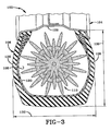
- a second configuration for a wheel with a monitoring device is indicated generally by the numeral 102 in Fig. 3 .
- the wheel includes a rim 104 and a tire 106 connected to the rim to form a sealed pneumatic chamber 108.
- Each configuration 100 and 102 further includes a monitoring device 110 loosely disposed within chamber 108 bounded only by tire 106 and rim 104.
- Monitoring device 110 includes a monitoring assembly 112 carried by a protective body 114 that has a central portion 116 and a plurality of fingers 118 projecting from the outer surface of central portion 116. Fingers 118 are adapted to support central portion 116 and monitoring assembly 112 in a spaced location from the inner surface 120 of tire 106 and the outer surface 122 of rim 104.
- Fingers 118 lift the antenna 124 of monitoring assembly 112 away from inner surface 120 of tire 106 to reduce signal attenuation by the crown of tire 106.
- fingers 118 are configured to substantially center monitoring assembly 112 with respect to the sidewall 126 of tire 106 and to limit the movement of monitoring device 110 within wheel 102. Fingers 118 will also help monitoring device 110 clear obstacles within tire 106 when monitoring device 110 is rolling along inner surface 120 of tire 106.
- Fingers 118 may also be sized to lift central portion 116 and monitoring assembly 112 above the liquid 128 in tire 106. Lifting monitoring assembly 112 and antenna 124 above liquid 128 increases the strength of the signals transmitted by antenna 124.
- Fingers 118 also function to cushion monitoring assembly 112 by absorbing impact forces experienced by monitoring device 110. In some large-size tires 106, the depth of liquid 128 may be three to eight inches.
- Fig. 1 depicts an embodiment wherein fingers 118 of monitoring device 110 are sized to lift monitoring assembly 112 above the upper surface of liquid 128.
- Fig. 3 depicts an embodiment wherein fingers 118 are sized to position monitoring assembly 112 in line with the central portion of sidewall 126.
- the configuration of Fig. 3 also limits the overall movement of monitoring device 110 because the combined length of two opposed fingers 118 and the diameter of central portion 116 is substantially equal to or slightly greater than the overall height 130 of tire 106. This configuration is especially useful when the maximum section width 132 of tire 106 is equal to or larger than height 130. In tire embodiments wherein section width 132 is less than height 130, the outer diameter of monitoring device 110 is sized to be slightly less than maximum section width 132 less the thickness of sidewalls 126.
- Monitoring device 110 in first configuration 100 may be configured to position the uppermost portion of monitoring device 110 above a reference plane that passes through a quarter height 130 of tire 106 as indicated by the numeral 134. In other configurations, monitoring device 110 may be sized so that dimension 134 is greater than one-half of dimension 130.
- protective body 114 may include an encapsulation layer 140 that immediately surrounds monitoring assembly 112.
- Encapsulation material 140 may be an epoxy material that cures into a substantially rigid protective layer.
- Encapsulation material 140 may be an epoxy, a plastic, a rubber, or a variety of other materials known to those of ordinary skill in the art. Exemplary encapsulation materials 140 are described in column 4 of U.S. Patent 6,030,478 .
- the body of central portion 116 may be fabricated from a material softer than encapsulation material 140 such as a rubber, foam rubber, or foam material.
- the outer surface of central portion 116 may be water tight to prevent central portion 116 from filling with liquid 128.
- any of a variety of materials may be used to form the body of central portion 116.
- Exemplary materials are silicone, rubber, and other foamable materials.
- the body of central portion 116 may also provide cushioning forces to monitoring assembly 112.
- Fingers 118 may be fabricated from the same material as central portion 116 and may integrally formed therewith. Fingers 118 may also be water tight to prevent the material of fingers 118 from absorbing or retaining liquid 128. In other embodiments, fingers 118 may be porous enabling them to absorb liquid 128. Fingers 118 are adapted to support monitoring device 110 without crumpling, bending, or buckling. Each finger 118 is also configured to withstand moderate G loads when monitoring device 110 is used with a wheel that rotates at high speeds. The combined weight of fingers 118 may be less than the weight of central portion 116 that includes the body of central portion 116, encapsulation material 140, and monitoring assembly 112.
- each finger 118 is substantially conical. Further, each finger 118 has a rounded tip 150 adapted to prevent monitoring device 110 from injuring inner surface 120 of tire 106. Tips 150 combine to define a sphere so that monitoring device 110 will freely roll about on a level surface. Fingers 118 may be evenly spaced about central portion 116 with six of fingers 118 disposed on three perpendicular reference axes. The length of each finger 118 may be half the diameter of central portion 116. In other embodiments, each finger 118 may have a length that is between one-quarter to three-quarters diameter of central portion 116.
Landscapes
- Engineering & Computer Science (AREA)
- Mechanical Engineering (AREA)
- Physics & Mathematics (AREA)
- General Physics & Mathematics (AREA)
- Measuring Fluid Pressure (AREA)
- Tires In General (AREA)
- Arrangements For Transmission Of Measured Signals (AREA)
Abstract
Description
- The present invention generally related to monitoring devices for pneumatic tires and, more particularly, to monitoring devices that are loosely disposed within the pneumatic tire and free to movement about bounded only by the rim and the tire mounted to the rim. Specifically, the present invention relates to the structure of a non-attached monitoring device that lifts the central portion of the monitoring device away from the footprint of the tire when the monitoring device is positioned in the footprint of the tire.
- Various type of tire monitoring devices are known in the art. Know monitoring devices are embedded within the tire, mounted to a surface of the tire, mounted to the rim (or the valve stem), or are loosely disposed within the tire. A common problem with the in-tire monitoring devices is that the tire and rim attenuate radio frequency transmissions from within the tire.
- Various solutions have been proposed to improve radio frequency transmissions from with a tire. These solutions include boosting the power of the transmitter and improving the configuration of the antenna. In non-attached monitoring devices, the problem of radio transmissions through the tire is significant when the non-attached monitoring device is resting in the footprint of the tire because the monitoring device is next to the ground and immediately adjacent the steel belts disposed in the crown of the tire. Another problem with existing monitoring devices is that liquid disposed in the tire can attenuate the radio transmissions when the antenna of the monitoring device is disposed under the upper surface of the liquid.
- The invention provides a monitoring device for a pneumatio tire that has an inner surface; the monitoring device including a body having a central portion; a monitoring assembly carried by the central portion of the body; and the body including a plurality of spaced fingers projecting from the central portion of the body; the fingers adapted to support the monitoring assembly in a spaced located from the inner surface of the tire.
- The invention also provides a wheel having a monitoring device. The wheel includes a rim having a radially outer surface; a tire having an inner surface; the tire mounted to the rim to define a chamber between the inner surface of the tire and the radially outer surface of the rim; a monitoring device disposed in the chamber; the monitoring device having a body having a central portion; a monitoring assembly carried by the central portion of the body; and the body including a plurality of spaced fingers projecting from the central portion of the body; the fingers adapted to support the monitoring assembly in a spaced located from the inner surface of the tire and the radially outer surface of the rim.
-
-
Fig. 1 is a section view of a wheel with a first configuration of the monitoring device of the invention disposed in the footprint of the tire. - Fi. 2 is a section view taken along line 2-2 of
Fig. 1 . -
Fig. 3 is a section view of a wheel with a second configuration of the monitoring device of the invention disposed in the footprint of the tire. - Similar numbers refer to similar parts throughout the specification.
- A first configuration of a wheel having a monitoring device is indicated generally by the
numeral 100 inFig. 1 . A second configuration for a wheel with a monitoring device is indicated generally by thenumeral 102 inFig. 3 . In eachconfiguration rim 104 and atire 106 connected to the rim to form a sealedpneumatic chamber 108. Eachconfiguration monitoring device 110 loosely disposed withinchamber 108 bounded only bytire 106 andrim 104.Monitoring device 110 includes amonitoring assembly 112 carried by aprotective body 114 that has acentral portion 116 and a plurality offingers 118 projecting from the outer surface ofcentral portion 116.Fingers 118 are adapted to supportcentral portion 116 andmonitoring assembly 112 in a spaced location from theinner surface 120 oftire 106 and theouter surface 122 ofrim 104. -
Fingers 118 lift theantenna 124 ofmonitoring assembly 112 away frominner surface 120 oftire 106 to reduce signal attenuation by the crown oftire 106. In the second configuration ofwheel 102,fingers 118 are configured to substantiallycenter monitoring assembly 112 with respect to thesidewall 126 oftire 106 and to limit the movement ofmonitoring device 110 withinwheel 102. Fingers 118 will also help monitoringdevice 110 clear obstacles withintire 106 when monitoringdevice 110 is rolling alonginner surface 120 oftire 106.Fingers 118 may also be sized to liftcentral portion 116 and monitoringassembly 112 above theliquid 128 intire 106.Lifting monitoring assembly 112 andantenna 124 aboveliquid 128 increases the strength of the signals transmitted byantenna 124.Fingers 118 also function tocushion monitoring assembly 112 by absorbing impact forces experienced bymonitoring device 110. In some large-size tires 106, the depth ofliquid 128 may be three to eight inches. -
Fig. 1 depicts an embodiment whereinfingers 118 ofmonitoring device 110 are sized to liftmonitoring assembly 112 above the upper surface ofliquid 128.Fig. 3 depicts an embodiment whereinfingers 118 are sized to positionmonitoring assembly 112 in line with the central portion ofsidewall 126. The configuration ofFig. 3 also limits the overall movement ofmonitoring device 110 because the combined length of two opposedfingers 118 and the diameter ofcentral portion 116 is substantially equal to or slightly greater than theoverall height 130 oftire 106. This configuration is especially useful when themaximum section width 132 oftire 106 is equal to or larger thanheight 130. In tire embodiments whereinsection width 132 is less thanheight 130, the outer diameter ofmonitoring device 110 is sized to be slightly less thanmaximum section width 132 less the thickness ofsidewalls 126.Monitoring device 110 infirst configuration 100 may be configured to position the uppermost portion ofmonitoring device 110 above a reference plane that passes through aquarter height 130 oftire 106 as indicated by thenumeral 134. In other configurations,monitoring device 110 may be sized so thatdimension 134 is greater than one-half ofdimension 130. - As shown in
Fig. 2 ,protective body 114 may include anencapsulation layer 140 that immediately surroundsmonitoring assembly 112.Encapsulation material 140 may be an epoxy material that cures into a substantially rigid protective layer.Encapsulation material 140 may be an epoxy, a plastic, a rubber, or a variety of other materials known to those of ordinary skill in the art.Exemplary encapsulation materials 140 are described in column 4 ofU.S. Patent 6,030,478 . The body ofcentral portion 116 may be fabricated from a material softer thanencapsulation material 140 such as a rubber, foam rubber, or foam material. The outer surface ofcentral portion 116 may be water tight to preventcentral portion 116 from filling withliquid 128. Any of a variety of materials may be used to form the body ofcentral portion 116. Exemplary materials are silicone, rubber, and other foamable materials. The body ofcentral portion 116 may also provide cushioning forces to monitoringassembly 112.Fingers 118 may be fabricated from the same material ascentral portion 116 and may integrally formed therewith.Fingers 118 may also be water tight to prevent the material offingers 118 from absorbing or retainingliquid 128. In other embodiments,fingers 118 may be porous enabling them to absorbliquid 128.Fingers 118 are adapted to supportmonitoring device 110 without crumpling, bending, or buckling. Eachfinger 118 is also configured to withstand moderate G loads when monitoringdevice 110 is used with a wheel that rotates at high speeds. The combined weight offingers 118 may be less than the weight ofcentral portion 116 that includes the body ofcentral portion 116,encapsulation material 140, andmonitoring assembly 112. - In the exemplary embodiment of the invention depicted in the drawings, each
finger 118 is substantially conical. Further, eachfinger 118 has arounded tip 150 adapted to preventmonitoring device 110 from injuringinner surface 120 oftire 106.Tips 150 combine to define a sphere so thatmonitoring device 110 will freely roll about on a level surface.Fingers 118 may be evenly spaced aboutcentral portion 116 with six offingers 118 disposed on three perpendicular reference axes. The length of eachfinger 118 may be half the diameter ofcentral portion 116. In other embodiments, eachfinger 118 may have a length that is between one-quarter to three-quarters diameter ofcentral portion 116. - In the foregoing description, certain terms have been used for brevity, clearness, and understanding. No unnecessary limitations are to be implied therefrom beyond the requirement of the prior art because such terms are used for descriptive purposes and are intended to be broadly construed.
- Moreover, the description and illustration of the invention is an example and the invention is not limited to the exact details shown or described.
Claims (16)
- A wheel (100; 102) having a monitoring device (110); the wheel (100, 102) comprising:a rim (104) having a radially outer surface (122);a tire (106) having an inner surface (120);the tire (106) mounted to the rim (104) to define a chamber (108) between the inner surface (120) of the tire (106) and the radially outer surface (122) of the rim (104);a monitoring device (110) disposed in the chamber (108); the monitoring device (110) having a body (114) having a central portion (116); a monitoring assembly (112) carried by the central portion (116) of the body (114); and the body (114) including a plurality of spaced fingers (118) projecting from the central portion (116) of the body (114); the fingers (118) adapted to support the monitoring assembly (112) spaced from the inner surface (120) of the tire (106) and the radially outer surface (122) of the rim (104).
- The wheel (100; 102) of claim 1, wherein the fingers (118) of the monitoring device (118) are configured to support the central portion (116) of the body (114) and the monitoring assembly (112) spaced from the inner surface (120) of the tire (106).
- The wheel (100; 102) of claim 1, wherein the fingers (118) are configured to lift the monitoring assembly (112) away from the inner surface (120) of the tire (106).
- The wheel (100; 102) of claim 1, wherein the fingers (118) of the monitoring device (110) simultaneously engage the inner surface (120) of the tire (106) and the outer surface (122) of the rim (104).
- The wheel (100; 102) of claim 1, wherein the height of the monitoring device (110) is greater than ¼ of the height of the tire (106).
- The wheel (100; 102) of claim 5, wherein the height of the monitoring device (110) is greater than ½ of the height of the tire (106).
- The wheel (100; 102) of claim 6, wherein the height of the monitoring device (110) is substantially equal to the height of the tire (106).
- The wheel (100; 102) of claim 1, wherein each projecting finger (118) is substantially conical.
- The wheel (100; 102) of claim 8, wherein each substantially conical finger (118) has a rounded tip (150).
- The wheel (100; 102) of claim 1, wherein each of the projecting fingers (118) has a length; the lengths being substantially equal such that the combination of projecting fingers (118) defines a sphere.
- The wheel (100; 102) of claim 1, wherein the projecting fingers (118) are evenly spaced about the body (114).
- The wheel (100; 102) of claim 1, wherein six of the projecting fingers (118) are disposed on three perpendicular axes.
- The wheel (100; 102) of claim 1, wherein the projecting fingers (118) are fabricated from a foam material.
- The wheel (100; 102) of claim 13, wherein the foam material is a rubber material.
- The wheel (100; 102) of claim 1, wherein the projecting fingers (118) are fabricated from a silicone material.
- The wheel (100; 102) of claim 14, wherein the fingers (118) are fabricated from a silicone foam.
Applications Claiming Priority (2)
| Application Number | Priority Date | Filing Date | Title |
|---|---|---|---|
| US10/394,971 US6910372B2 (en) | 2003-03-21 | 2003-03-21 | Non-attached electronic monitoring device for tire |
| EP04757735A EP1606126B1 (en) | 2003-03-21 | 2004-03-13 | Non-attached electronic monitoring device for tire |
Related Parent Applications (1)
| Application Number | Title | Priority Date | Filing Date |
|---|---|---|---|
| EP04757735.8 Division | 2004-03-13 |
Publications (2)
| Publication Number | Publication Date |
|---|---|
| EP2202100A1 true EP2202100A1 (en) | 2010-06-30 |
| EP2202100B1 EP2202100B1 (en) | 2011-09-07 |
Family
ID=32988512
Family Applications (2)
| Application Number | Title | Priority Date | Filing Date |
|---|---|---|---|
| EP10003207A Expired - Lifetime EP2202100B1 (en) | 2003-03-21 | 2004-03-13 | Wheel with a non-attached monitoring device |
| EP04757735A Expired - Lifetime EP1606126B1 (en) | 2003-03-21 | 2004-03-13 | Non-attached electronic monitoring device for tire |
Family Applications After (1)
| Application Number | Title | Priority Date | Filing Date |
|---|---|---|---|
| EP04757735A Expired - Lifetime EP1606126B1 (en) | 2003-03-21 | 2004-03-13 | Non-attached electronic monitoring device for tire |
Country Status (11)
| Country | Link |
|---|---|
| US (1) | US6910372B2 (en) |
| EP (2) | EP2202100B1 (en) |
| JP (1) | JP4336367B2 (en) |
| KR (1) | KR101094652B1 (en) |
| AU (1) | AU2004223894B2 (en) |
| BR (1) | BRPI0408528B1 (en) |
| CA (1) | CA2514835C (en) |
| DE (1) | DE602004027712D1 (en) |
| ES (2) | ES2344205T3 (en) |
| WO (1) | WO2004085176A2 (en) |
| ZA (1) | ZA200506882B (en) |
Families Citing this family (14)
| Publication number | Priority date | Publication date | Assignee | Title |
|---|---|---|---|---|
| TWI317703B (en) * | 2006-12-12 | 2009-12-01 | Ind Tech Res Inst | Tire and detection and alarm mechanism thereof |
| US7478554B2 (en) * | 2006-12-19 | 2009-01-20 | The Goodyear Tire & Rubber Company | Rim mounted tire pressure monitoring system |
| US9016117B2 (en) * | 2012-05-23 | 2015-04-28 | Yuval Solomon | Tire monitoring apparatus, system and method of using the same |
| US8939020B2 (en) * | 2012-12-05 | 2015-01-27 | Caterpillar Inc. | Spherical monitoring device for pneumatic tires |
| US20170328197A1 (en) * | 2016-05-13 | 2017-11-16 | Ningbo Wanyou Deepwater Energy Science & Technolog Co.,Ltd. | Data Logger, Manufacturing Method Thereof and Real-time Measurement System Thereof |
| US20170350241A1 (en) * | 2016-05-13 | 2017-12-07 | Ningbo Wanyou Deepwater Energy Science & Technology Co.,Ltd. | Data Logger and Charger Thereof |
| TWI643765B (en) * | 2017-10-13 | 2018-12-11 | 為升電裝工業股份有限公司 | Tire pressure detector with wheel balancing function and the wheel balancing system thereof |
| CN108327466A (en) * | 2018-03-30 | 2018-07-27 | 上海为彪汽配制造有限公司 | Tyre pressure sensor with shell protection |
| AU2019206104A1 (en) * | 2018-07-25 | 2020-02-13 | Cub Elecparts Inc. | Spherical tire pressure detection device |
| CN112109504B (en) * | 2019-06-20 | 2022-09-20 | 上海为彪汽配制造有限公司 | Floating tyre pressure sensing device |
| JP2022043947A (en) * | 2020-09-04 | 2022-03-16 | 太平洋工業株式会社 | Generator and tire condition monitoring device |
| GB2602260A (en) | 2020-12-16 | 2022-06-29 | Airbus Operations Ltd | Wheel assembly sensor apparatus |
| GB2602012A (en) | 2020-12-15 | 2022-06-22 | Airbus Operations Ltd | Tyre monitor |
| JP2025127769A (en) * | 2024-02-21 | 2025-09-02 | 株式会社Nippo | Tire roller and tire heating method for tire roller |
Citations (2)
| Publication number | Priority date | Publication date | Assignee | Title |
|---|---|---|---|---|
| EP1000776A2 (en) * | 1998-11-13 | 2000-05-17 | BRIDGESTONE/FIRESTONE, Research, Inc. | Non-attached monitoring assembly for pneumatic tire |
| WO2002002358A1 (en) * | 2000-06-30 | 2002-01-10 | Bridgestone/Firestone North American Tire, Llc | Non-attached monitoring assembly for pneumatic tire |
Family Cites Families (10)
| Publication number | Priority date | Publication date | Assignee | Title |
|---|---|---|---|---|
| US3894421A (en) | 1973-08-17 | 1975-07-15 | Lawrence R Sperberg | Method of measuring tire dynamic strength |
| US4067235A (en) | 1974-11-27 | 1978-01-10 | Consolidated Freightways, Inc. | Method and apparatus for measuring air pressure in pneumatic tires |
| JPS63291709A (en) * | 1987-05-26 | 1988-11-29 | Honda Motor Co Ltd | pneumatic tires |
| DE3902644A1 (en) | 1989-01-30 | 1990-08-02 | Bosch Gmbh Robert | TIRE PRESSURE MONITORS FOR VEHICLES |
| US5500065A (en) | 1994-06-03 | 1996-03-19 | Bridgestone/Firestone, Inc. | Method for embedding a monitoring device within a tire during manufacture |
| JP2759073B2 (en) | 1996-06-28 | 1998-05-28 | 伊三五 美浦 | Pneumatic tire |
| US6486771B1 (en) | 1998-03-11 | 2002-11-26 | Fuller Brothers, Inc. | Tire inflation gas temperature, pressure, and oxygen monitoring system |
| US6543277B2 (en) | 1998-11-13 | 2003-04-08 | Bridgestone/Firestone North American Tire, Llc | Non-attached monitoring assembly for pneumatic tire |
| US6612657B1 (en) * | 2000-11-01 | 2003-09-02 | Gunite Corporation | Outboard ribbed wheel hub |
| JP4554827B2 (en) * | 2001-01-24 | 2010-09-29 | 本田技研工業株式会社 | Wheel pressure sensor mounting structure |
-
2003
- 2003-03-21 US US10/394,971 patent/US6910372B2/en not_active Expired - Lifetime
-
2004
- 2004-03-13 JP JP2006507226A patent/JP4336367B2/en not_active Expired - Fee Related
- 2004-03-13 AU AU2004223894A patent/AU2004223894B2/en not_active Ceased
- 2004-03-13 ES ES04757735T patent/ES2344205T3/en not_active Expired - Lifetime
- 2004-03-13 BR BRPI0408528A patent/BRPI0408528B1/en not_active IP Right Cessation
- 2004-03-13 WO PCT/US2004/007951 patent/WO2004085176A2/en not_active Ceased
- 2004-03-13 EP EP10003207A patent/EP2202100B1/en not_active Expired - Lifetime
- 2004-03-13 EP EP04757735A patent/EP1606126B1/en not_active Expired - Lifetime
- 2004-03-13 ES ES10003207T patent/ES2370979T3/en not_active Expired - Lifetime
- 2004-03-13 KR KR1020057016225A patent/KR101094652B1/en not_active Expired - Fee Related
- 2004-03-13 CA CA2514835A patent/CA2514835C/en not_active Expired - Fee Related
- 2004-03-13 DE DE602004027712T patent/DE602004027712D1/en not_active Expired - Lifetime
-
2005
- 2005-08-26 ZA ZA2005/06882A patent/ZA200506882B/en unknown
Patent Citations (2)
| Publication number | Priority date | Publication date | Assignee | Title |
|---|---|---|---|---|
| EP1000776A2 (en) * | 1998-11-13 | 2000-05-17 | BRIDGESTONE/FIRESTONE, Research, Inc. | Non-attached monitoring assembly for pneumatic tire |
| WO2002002358A1 (en) * | 2000-06-30 | 2002-01-10 | Bridgestone/Firestone North American Tire, Llc | Non-attached monitoring assembly for pneumatic tire |
Also Published As
| Publication number | Publication date |
|---|---|
| CA2514835A1 (en) | 2004-10-07 |
| EP1606126A2 (en) | 2005-12-21 |
| ES2370979T3 (en) | 2011-12-26 |
| EP2202100B1 (en) | 2011-09-07 |
| KR20050111606A (en) | 2005-11-25 |
| US20040182146A1 (en) | 2004-09-23 |
| CA2514835C (en) | 2012-02-14 |
| KR101094652B1 (en) | 2011-12-20 |
| ES2344205T3 (en) | 2010-08-20 |
| JP4336367B2 (en) | 2009-09-30 |
| ZA200506882B (en) | 2006-04-26 |
| WO2004085176A2 (en) | 2004-10-07 |
| BRPI0408528A (en) | 2006-03-07 |
| JP2006520719A (en) | 2006-09-14 |
| US6910372B2 (en) | 2005-06-28 |
| BRPI0408528B1 (en) | 2015-10-27 |
| EP1606126B1 (en) | 2010-06-16 |
| AU2004223894A1 (en) | 2004-10-07 |
| WO2004085176A3 (en) | 2004-12-29 |
| DE602004027712D1 (en) | 2010-07-29 |
| AU2004223894B2 (en) | 2009-08-06 |
Similar Documents
| Publication | Publication Date | Title |
|---|---|---|
| EP2202100B1 (en) | Wheel with a non-attached monitoring device | |
| US6543277B2 (en) | Non-attached monitoring assembly for pneumatic tire | |
| US6516660B1 (en) | Non-attached monitoring assembly for pneumatic tire | |
| EP2397342A1 (en) | Non-pneumatic tire | |
| EP1562763B1 (en) | Non-attached monitoring assembly for pneumatic tire | |
| KR20000034976A (en) | Non-attached monitoring assembly for pneumatic tire | |
| AU2001271512A1 (en) | Non-attached monitoring assembly for pneumatic tire | |
| US20130248069A1 (en) | Tire with inner core | |
| US7044180B2 (en) | Run-flat insert for tires | |
| KR20100005511A (en) | Low noise pneumatic tire attached the absorbing damper | |
| KR101762303B1 (en) | Airless tire | |
| KR101586365B1 (en) | Runflat tire | |
| MXPA05010004A (en) | Non-attached electronic monitoring device for tire | |
| KR100774495B1 (en) | Non-pneumatic tires | |
| KR100767800B1 (en) | Run Flat Tires Prevent Rim Rips | |
| CN216662355U (en) | Portable inflatable jack for automobile | |
| CN206106816U (en) | Agricultural non -pneumatic tire |
Legal Events
| Date | Code | Title | Description |
|---|---|---|---|
| PUAI | Public reference made under article 153(3) epc to a published international application that has entered the european phase |
Free format text: ORIGINAL CODE: 0009012 |
|
| AC | Divisional application: reference to earlier application |
Ref document number: 1606126 Country of ref document: EP Kind code of ref document: P |
|
| AK | Designated contracting states |
Kind code of ref document: A1 Designated state(s): DE ES FR GB IT |
|
| 17P | Request for examination filed |
Effective date: 20101214 |
|
| RIC1 | Information provided on ipc code assigned before grant |
Ipc: B60C 23/04 20060101AFI20110215BHEP |
|
| GRAP | Despatch of communication of intention to grant a patent |
Free format text: ORIGINAL CODE: EPIDOSNIGR1 |
|
| GRAC | Information related to communication of intention to grant a patent modified |
Free format text: ORIGINAL CODE: EPIDOSCIGR1 |
|
| GRAS | Grant fee paid |
Free format text: ORIGINAL CODE: EPIDOSNIGR3 |
|
| GRAA | (expected) grant |
Free format text: ORIGINAL CODE: 0009210 |
|
| REG | Reference to a national code |
Ref country code: GB Ref legal event code: FG4D |
|
| REG | Reference to a national code |
Ref country code: DE Ref legal event code: R096 Ref document number: 602004034291 Country of ref document: DE Effective date: 20111117 |
|
| REG | Reference to a national code |
Ref country code: ES Ref legal event code: FG2A Ref document number: 2370979 Country of ref document: ES Kind code of ref document: T3 Effective date: 20111226 |
|
| PLBE | No opposition filed within time limit |
Free format text: ORIGINAL CODE: 0009261 |
|
| STAA | Information on the status of an ep patent application or granted ep patent |
Free format text: STATUS: NO OPPOSITION FILED WITHIN TIME LIMIT |
|
| 26N | No opposition filed |
Effective date: 20120611 |
|
| REG | Reference to a national code |
Ref country code: DE Ref legal event code: R097 Ref document number: 602004034291 Country of ref document: DE Effective date: 20120611 |
|
| REG | Reference to a national code |
Ref country code: FR Ref legal event code: PLFP Year of fee payment: 13 |
|
| REG | Reference to a national code |
Ref country code: FR Ref legal event code: PLFP Year of fee payment: 14 |
|
| PGFP | Annual fee paid to national office [announced via postgrant information from national office to epo] |
Ref country code: FR Payment date: 20170222 Year of fee payment: 14 |
|
| PGFP | Annual fee paid to national office [announced via postgrant information from national office to epo] |
Ref country code: GB Payment date: 20170223 Year of fee payment: 14 |
|
| PGFP | Annual fee paid to national office [announced via postgrant information from national office to epo] |
Ref country code: IT Payment date: 20170310 Year of fee payment: 14 Ref country code: ES Payment date: 20170308 Year of fee payment: 14 |
|
| PGFP | Annual fee paid to national office [announced via postgrant information from national office to epo] |
Ref country code: DE Payment date: 20170331 Year of fee payment: 14 |
|
| REG | Reference to a national code |
Ref country code: DE Ref legal event code: R119 Ref document number: 602004034291 Country of ref document: DE |
|
| GBPC | Gb: european patent ceased through non-payment of renewal fee |
Effective date: 20180313 |
|
| PG25 | Lapsed in a contracting state [announced via postgrant information from national office to epo] |
Ref country code: DE Free format text: LAPSE BECAUSE OF NON-PAYMENT OF DUE FEES Effective date: 20181002 |
|
| PG25 | Lapsed in a contracting state [announced via postgrant information from national office to epo] |
Ref country code: IT Free format text: LAPSE BECAUSE OF NON-PAYMENT OF DUE FEES Effective date: 20180313 Ref country code: GB Free format text: LAPSE BECAUSE OF NON-PAYMENT OF DUE FEES Effective date: 20180313 |
|
| PG25 | Lapsed in a contracting state [announced via postgrant information from national office to epo] |
Ref country code: FR Free format text: LAPSE BECAUSE OF NON-PAYMENT OF DUE FEES Effective date: 20180331 |
|
| REG | Reference to a national code |
Ref country code: ES Ref legal event code: FD2A Effective date: 20190911 |
|
| PG25 | Lapsed in a contracting state [announced via postgrant information from national office to epo] |
Ref country code: ES Free format text: LAPSE BECAUSE OF NON-PAYMENT OF DUE FEES Effective date: 20180314 |