EP2202045A1 - Rubber coating method for metallic element wire, cord manufacturing method, cord, rubber coating apparatus, and cord manufacturing apparatus - Google Patents
Rubber coating method for metallic element wire, cord manufacturing method, cord, rubber coating apparatus, and cord manufacturing apparatus Download PDFInfo
- Publication number
- EP2202045A1 EP2202045A1 EP08832452A EP08832452A EP2202045A1 EP 2202045 A1 EP2202045 A1 EP 2202045A1 EP 08832452 A EP08832452 A EP 08832452A EP 08832452 A EP08832452 A EP 08832452A EP 2202045 A1 EP2202045 A1 EP 2202045A1
- Authority
- EP
- European Patent Office
- Prior art keywords
- rubber
- cord
- filament
- metal filaments
- filaments
- Prior art date
- Legal status (The legal status is an assumption and is not a legal conclusion. Google has not performed a legal analysis and makes no representation as to the accuracy of the status listed.)
- Granted
Links
Images

Classifications
-
- B—PERFORMING OPERATIONS; TRANSPORTING
- B29—WORKING OF PLASTICS; WORKING OF SUBSTANCES IN A PLASTIC STATE IN GENERAL
- B29C—SHAPING OR JOINING OF PLASTICS; SHAPING OF MATERIAL IN A PLASTIC STATE, NOT OTHERWISE PROVIDED FOR; AFTER-TREATMENT OF THE SHAPED PRODUCTS, e.g. REPAIRING
- B29C48/00—Extrusion moulding, i.e. expressing the moulding material through a die or nozzle which imparts the desired form; Apparatus therefor
- B29C48/03—Extrusion moulding, i.e. expressing the moulding material through a die or nozzle which imparts the desired form; Apparatus therefor characterised by the shape of the extruded material at extrusion
- B29C48/05—Filamentary, e.g. strands
-
- B—PERFORMING OPERATIONS; TRANSPORTING
- B29—WORKING OF PLASTICS; WORKING OF SUBSTANCES IN A PLASTIC STATE IN GENERAL
- B29D—PRODUCING PARTICULAR ARTICLES FROM PLASTICS OR FROM SUBSTANCES IN A PLASTIC STATE
- B29D30/00—Producing pneumatic or solid tyres or parts thereof
- B29D30/06—Pneumatic tyres or parts thereof (e.g. produced by casting, moulding, compression moulding, injection moulding, centrifugal casting)
- B29D30/38—Textile inserts, e.g. cord or canvas layers, for tyres; Treatment of inserts prior to building the tyre
-
- D—TEXTILES; PAPER
- D01—NATURAL OR MAN-MADE THREADS OR FIBRES; SPINNING
- D01D—MECHANICAL METHODS OR APPARATUS IN THE MANUFACTURE OF ARTIFICIAL FILAMENTS, THREADS, FIBRES, BRISTLES OR RIBBONS
- D01D11/00—Other features of manufacture
-
- D—TEXTILES; PAPER
- D07—ROPES; CABLES OTHER THAN ELECTRIC
- D07B—ROPES OR CABLES IN GENERAL
- D07B1/00—Constructional features of ropes or cables
- D07B1/06—Ropes or cables built-up from metal wires, e.g. of section wires around a hemp core
- D07B1/0606—Reinforcing cords for rubber or plastic articles
- D07B1/062—Reinforcing cords for rubber or plastic articles the reinforcing cords being characterised by the strand configuration
-
- D—TEXTILES; PAPER
- D07—ROPES; CABLES OTHER THAN ELECTRIC
- D07B—ROPES OR CABLES IN GENERAL
- D07B7/00—Details of, or auxiliary devices incorporated in, rope- or cable-making machines; Auxiliary apparatus associated with such machines
- D07B7/02—Machine details; Auxiliary devices
- D07B7/14—Machine details; Auxiliary devices for coating or wrapping ropes, cables, or component strands thereof
- D07B7/145—Coating or filling-up interstices
-
- B—PERFORMING OPERATIONS; TRANSPORTING
- B29—WORKING OF PLASTICS; WORKING OF SUBSTANCES IN A PLASTIC STATE IN GENERAL
- B29C—SHAPING OR JOINING OF PLASTICS; SHAPING OF MATERIAL IN A PLASTIC STATE, NOT OTHERWISE PROVIDED FOR; AFTER-TREATMENT OF THE SHAPED PRODUCTS, e.g. REPAIRING
- B29C48/00—Extrusion moulding, i.e. expressing the moulding material through a die or nozzle which imparts the desired form; Apparatus therefor
- B29C48/03—Extrusion moulding, i.e. expressing the moulding material through a die or nozzle which imparts the desired form; Apparatus therefor characterised by the shape of the extruded material at extrusion
- B29C48/06—Rod-shaped
-
- B—PERFORMING OPERATIONS; TRANSPORTING
- B29—WORKING OF PLASTICS; WORKING OF SUBSTANCES IN A PLASTIC STATE IN GENERAL
- B29C—SHAPING OR JOINING OF PLASTICS; SHAPING OF MATERIAL IN A PLASTIC STATE, NOT OTHERWISE PROVIDED FOR; AFTER-TREATMENT OF THE SHAPED PRODUCTS, e.g. REPAIRING
- B29C48/00—Extrusion moulding, i.e. expressing the moulding material through a die or nozzle which imparts the desired form; Apparatus therefor
- B29C48/15—Extrusion moulding, i.e. expressing the moulding material through a die or nozzle which imparts the desired form; Apparatus therefor incorporating preformed parts or layers, e.g. extrusion moulding around inserts
- B29C48/154—Coating solid articles, i.e. non-hollow articles
-
- B—PERFORMING OPERATIONS; TRANSPORTING
- B29—WORKING OF PLASTICS; WORKING OF SUBSTANCES IN A PLASTIC STATE IN GENERAL
- B29C—SHAPING OR JOINING OF PLASTICS; SHAPING OF MATERIAL IN A PLASTIC STATE, NOT OTHERWISE PROVIDED FOR; AFTER-TREATMENT OF THE SHAPED PRODUCTS, e.g. REPAIRING
- B29C48/00—Extrusion moulding, i.e. expressing the moulding material through a die or nozzle which imparts the desired form; Apparatus therefor
- B29C48/15—Extrusion moulding, i.e. expressing the moulding material through a die or nozzle which imparts the desired form; Apparatus therefor incorporating preformed parts or layers, e.g. extrusion moulding around inserts
- B29C48/156—Coating two or more articles simultaneously
-
- B—PERFORMING OPERATIONS; TRANSPORTING
- B29—WORKING OF PLASTICS; WORKING OF SUBSTANCES IN A PLASTIC STATE IN GENERAL
- B29C—SHAPING OR JOINING OF PLASTICS; SHAPING OF MATERIAL IN A PLASTIC STATE, NOT OTHERWISE PROVIDED FOR; AFTER-TREATMENT OF THE SHAPED PRODUCTS, e.g. REPAIRING
- B29C48/00—Extrusion moulding, i.e. expressing the moulding material through a die or nozzle which imparts the desired form; Apparatus therefor
- B29C48/16—Articles comprising two or more components, e.g. co-extruded layers
- B29C48/18—Articles comprising two or more components, e.g. co-extruded layers the components being layers
- B29C48/21—Articles comprising two or more components, e.g. co-extruded layers the components being layers the layers being joined at their surfaces
-
- B—PERFORMING OPERATIONS; TRANSPORTING
- B29—WORKING OF PLASTICS; WORKING OF SUBSTANCES IN A PLASTIC STATE IN GENERAL
- B29C—SHAPING OR JOINING OF PLASTICS; SHAPING OF MATERIAL IN A PLASTIC STATE, NOT OTHERWISE PROVIDED FOR; AFTER-TREATMENT OF THE SHAPED PRODUCTS, e.g. REPAIRING
- B29C48/00—Extrusion moulding, i.e. expressing the moulding material through a die or nozzle which imparts the desired form; Apparatus therefor
- B29C48/25—Component parts, details or accessories; Auxiliary operations
- B29C48/28—Storing of extruded material, e.g. by winding up or stacking
-
- B—PERFORMING OPERATIONS; TRANSPORTING
- B29—WORKING OF PLASTICS; WORKING OF SUBSTANCES IN A PLASTIC STATE IN GENERAL
- B29C—SHAPING OR JOINING OF PLASTICS; SHAPING OF MATERIAL IN A PLASTIC STATE, NOT OTHERWISE PROVIDED FOR; AFTER-TREATMENT OF THE SHAPED PRODUCTS, e.g. REPAIRING
- B29C48/00—Extrusion moulding, i.e. expressing the moulding material through a die or nozzle which imparts the desired form; Apparatus therefor
- B29C48/25—Component parts, details or accessories; Auxiliary operations
- B29C48/285—Feeding the extrusion material to the extruder
- B29C48/288—Feeding the extrusion material to the extruder in solid form, e.g. powder or granules
- B29C48/2883—Feeding the extrusion material to the extruder in solid form, e.g. powder or granules of preformed parts, e.g. inserts, retaining their shape during the extrusion process
-
- B—PERFORMING OPERATIONS; TRANSPORTING
- B29—WORKING OF PLASTICS; WORKING OF SUBSTANCES IN A PLASTIC STATE IN GENERAL
- B29C—SHAPING OR JOINING OF PLASTICS; SHAPING OF MATERIAL IN A PLASTIC STATE, NOT OTHERWISE PROVIDED FOR; AFTER-TREATMENT OF THE SHAPED PRODUCTS, e.g. REPAIRING
- B29C48/00—Extrusion moulding, i.e. expressing the moulding material through a die or nozzle which imparts the desired form; Apparatus therefor
- B29C48/25—Component parts, details or accessories; Auxiliary operations
- B29C48/30—Extrusion nozzles or dies
- B29C48/32—Extrusion nozzles or dies with annular openings, e.g. for forming tubular articles
- B29C48/34—Cross-head annular extrusion nozzles, i.e. for simultaneously receiving moulding material and the preform to be coated
-
- B—PERFORMING OPERATIONS; TRANSPORTING
- B29—WORKING OF PLASTICS; WORKING OF SUBSTANCES IN A PLASTIC STATE IN GENERAL
- B29D—PRODUCING PARTICULAR ARTICLES FROM PLASTICS OR FROM SUBSTANCES IN A PLASTIC STATE
- B29D30/00—Producing pneumatic or solid tyres or parts thereof
- B29D30/06—Pneumatic tyres or parts thereof (e.g. produced by casting, moulding, compression moulding, injection moulding, centrifugal casting)
- B29D30/38—Textile inserts, e.g. cord or canvas layers, for tyres; Treatment of inserts prior to building the tyre
- B29D2030/381—Textile inserts, e.g. cord or canvas layers, for tyres; Treatment of inserts prior to building the tyre the inserts incorporating reinforcing parallel cords; manufacture thereof
-
- B—PERFORMING OPERATIONS; TRANSPORTING
- B29—WORKING OF PLASTICS; WORKING OF SUBSTANCES IN A PLASTIC STATE IN GENERAL
- B29K—INDEXING SCHEME ASSOCIATED WITH SUBCLASSES B29B, B29C OR B29D, RELATING TO MOULDING MATERIALS OR TO MATERIALS FOR MOULDS, REINFORCEMENTS, FILLERS OR PREFORMED PARTS, e.g. INSERTS
- B29K2021/00—Use of unspecified rubbers as moulding material
-
- B—PERFORMING OPERATIONS; TRANSPORTING
- B29—WORKING OF PLASTICS; WORKING OF SUBSTANCES IN A PLASTIC STATE IN GENERAL
- B29K—INDEXING SCHEME ASSOCIATED WITH SUBCLASSES B29B, B29C OR B29D, RELATING TO MOULDING MATERIALS OR TO MATERIALS FOR MOULDS, REINFORCEMENTS, FILLERS OR PREFORMED PARTS, e.g. INSERTS
- B29K2105/00—Condition, form or state of moulded material or of the material to be shaped
- B29K2105/06—Condition, form or state of moulded material or of the material to be shaped containing reinforcements, fillers or inserts
- B29K2105/08—Condition, form or state of moulded material or of the material to be shaped containing reinforcements, fillers or inserts of continuous length, e.g. cords, rovings, mats, fabrics, strands or yarns
-
- B—PERFORMING OPERATIONS; TRANSPORTING
- B29—WORKING OF PLASTICS; WORKING OF SUBSTANCES IN A PLASTIC STATE IN GENERAL
- B29L—INDEXING SCHEME ASSOCIATED WITH SUBCLASS B29C, RELATING TO PARTICULAR ARTICLES
- B29L2029/00—Belts or bands
-
- B—PERFORMING OPERATIONS; TRANSPORTING
- B29—WORKING OF PLASTICS; WORKING OF SUBSTANCES IN A PLASTIC STATE IN GENERAL
- B29L—INDEXING SCHEME ASSOCIATED WITH SUBCLASS B29C, RELATING TO PARTICULAR ARTICLES
- B29L2030/00—Pneumatic or solid tyres or parts thereof
- B29L2030/003—Plies; Breakers
- B29L2030/005—Belts
-
- D—TEXTILES; PAPER
- D07—ROPES; CABLES OTHER THAN ELECTRIC
- D07B—ROPES OR CABLES IN GENERAL
- D07B2201/00—Ropes or cables
- D07B2201/20—Rope or cable components
- D07B2201/2015—Strands
- D07B2201/2016—Strands characterised by their cross-sectional shape
-
- D—TEXTILES; PAPER
- D07—ROPES; CABLES OTHER THAN ELECTRIC
- D07B—ROPES OR CABLES IN GENERAL
- D07B2201/00—Ropes or cables
- D07B2201/20—Rope or cable components
- D07B2201/2015—Strands
- D07B2201/2023—Strands with core
-
- D—TEXTILES; PAPER
- D07—ROPES; CABLES OTHER THAN ELECTRIC
- D07B—ROPES OR CABLES IN GENERAL
- D07B2201/00—Ropes or cables
- D07B2201/20—Rope or cable components
- D07B2201/2015—Strands
- D07B2201/2024—Strands twisted
-
- D—TEXTILES; PAPER
- D07—ROPES; CABLES OTHER THAN ELECTRIC
- D07B—ROPES OR CABLES IN GENERAL
- D07B2201/00—Ropes or cables
- D07B2201/20—Rope or cable components
- D07B2201/2015—Strands
- D07B2201/2042—Strands characterised by a coating
-
- D—TEXTILES; PAPER
- D07—ROPES; CABLES OTHER THAN ELECTRIC
- D07B—ROPES OR CABLES IN GENERAL
- D07B2201/00—Ropes or cables
- D07B2201/20—Rope or cable components
- D07B2201/2015—Strands
- D07B2201/2046—Strands comprising fillers
-
- D—TEXTILES; PAPER
- D07—ROPES; CABLES OTHER THAN ELECTRIC
- D07B—ROPES OR CABLES IN GENERAL
- D07B2201/00—Ropes or cables
- D07B2201/20—Rope or cable components
- D07B2201/2047—Cores
- D07B2201/2052—Cores characterised by their structure
- D07B2201/2059—Cores characterised by their structure comprising wires
- D07B2201/206—Cores characterised by their structure comprising wires arranged parallel to the axis
-
- D—TEXTILES; PAPER
- D07—ROPES; CABLES OTHER THAN ELECTRIC
- D07B—ROPES OR CABLES IN GENERAL
- D07B2201/00—Ropes or cables
- D07B2201/20—Rope or cable components
- D07B2201/2047—Cores
- D07B2201/2052—Cores characterised by their structure
- D07B2201/2059—Cores characterised by their structure comprising wires
- D07B2201/2062—Cores characterised by their structure comprising wires comprising fillers
-
- D—TEXTILES; PAPER
- D07—ROPES; CABLES OTHER THAN ELECTRIC
- D07B—ROPES OR CABLES IN GENERAL
- D07B2201/00—Ropes or cables
- D07B2201/20—Rope or cable components
- D07B2201/2075—Fillers
- D07B2201/2079—Fillers characterised by the kind or amount of filling
- D07B2201/2081—Fillers characterised by the kind or amount of filling having maximum filling
-
- Y—GENERAL TAGGING OF NEW TECHNOLOGICAL DEVELOPMENTS; GENERAL TAGGING OF CROSS-SECTIONAL TECHNOLOGIES SPANNING OVER SEVERAL SECTIONS OF THE IPC; TECHNICAL SUBJECTS COVERED BY FORMER USPC CROSS-REFERENCE ART COLLECTIONS [XRACs] AND DIGESTS
- Y10—TECHNICAL SUBJECTS COVERED BY FORMER USPC
- Y10T—TECHNICAL SUBJECTS COVERED BY FORMER US CLASSIFICATION
- Y10T428/00—Stock material or miscellaneous articles
- Y10T428/29—Coated or structually defined flake, particle, cell, strand, strand portion, rod, filament, macroscopic fiber or mass thereof
- Y10T428/2913—Rod, strand, filament or fiber
- Y10T428/2929—Bicomponent, conjugate, composite or collateral fibers or filaments [i.e., coextruded sheath-core or side-by-side type]
- Y10T428/2931—Fibers or filaments nonconcentric [e.g., side-by-side or eccentric, etc.]
Definitions
- the present invention relates to a method of coating a metal filament as a constituent of, for example, a cord for reinforcing a rubber article, with rubber, a method of producing a cord by twisting metal filaments as constituents of a cord by a filament twisting machine, a cord formed by twisting rubber-coated metal filaments by a filament twisting machine, a rubber coating apparatus for coating a metal filament with rubber, and a cord producing apparatus.
- a cord for reinforcing a tire is required, above all, to be capable of suppressing deterioration of cord durability, which deterioration is due to growth of corrosion caused by moisture which has entered inside the tire.
- JP 2002-302884 and JP 2002-302885 each propose a technology of coating respective filaments with unvulcanized rubber in an unvulcanized rubber coating machine; then parting the respective filaments coated with unvulcanized rubber by a line-parting machine (a guide) and supply the parted filaments to a buncher twisting machine; and simultaneously twisting these filaments coated with unvulcanized rubber by using the buncher twisting machine, to produce a cord.
- JP 2002-266266 proposes a technology of coating the periphery of a core as plural twisted filaments with unvulcanized rubber by using a rubber extruder; and twining by using a buncher twisting machine plural filaments, which are to form a sheath, around the core coated with unvulcanized rubber, to form a cord.
- the twist originated by the buncher twisting machine is transmitted to the filaments which are to form a core when the periphery of the core is coated with rubber by the rubber extruder.
- a core is coated with unvulcanized rubber in a state where the core has a twisted structure of 1 ⁇ 3.
- a closed space which is not filled with unvulcanized rubber, is generated in the core portion of the filaments.
- an object of the present invention is to make it possible to provide a cord, in particular, a cord for reinforcing a rubber article in which rubber permeation properties are improved by coating filaments as constituents of the cord with rubber in a reliable and stable manner.
- filaments can be coated with rubber in a reliable and stable manner by laying the filaments horizontally and coating these filaments with rubber at a time when the filaments are coated with rubber and suppressing twisting of the filaments originated by a twisting machine when the filaments are twisted to a cord, to complete the present invention.
- the gist of the present invention is as follows: (1) a method of coating a metal filament with rubber, characterized in that , when the metal filament is guided to an extruder and extruded together with rubber from a mouthpiece of the extruder so that the metal filament is coated with the rubber, plural metal filaments are juxtaposed in the mouthpiece and extruded together with rubber;
- a cord having a single twist double layered structure formed by arranging plural metal filaments as a sheath around plural metal filaments as a core coated with rubber by the method of (1) above and twisting the core and the sheath simultaneously;
- a rubber coating apparatus including an extruder and a mouthpiece, characterized in that the mouthpiece has a width which allows plural metal filaments to be arranged in a juxtaposed manner.
- a cord producing apparatus including the rubber coating apparatus as described in (7) above and a filament twisting machine, characterized in that it further includes a twist-eliminating machine disposed on the outlet side of the rubber coating apparatus, for eliminating a twist transmitted from the filament twisting machine to a metal filament.
- plural metal filaments can be coated with rubber in a reliable and stable manner by juxtaposing plural metal filaments in a mouthpiece of an extruder and coating these juxtaposed metal filaments with rubber at a time.
- the metal filaments can be twisted to form a cord without experiencing the rubber peeling off therefrom.
- twisting of a metal filament can be suppressed by eliminating on the outlet side of the mouthpiece a twist transmitted from a filament twisting machine to the metal filament, whereby the filament can be coated with rubber in a reliable and stable manner.
- a cord having excellent durability can be obtained.
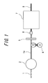
- FIG. 1 is a view showing a method of producing a cord according to the present invention.
- FIG. 1 shows a process of twisting metal filaments to produce a cord.
- plural (three in the drawing) metal filaments 1 are supplied to a rubber coating apparatus 2 so that the metal filaments 1 are coated with rubber 3, and the metal filaments 1a coated with rubber 3 are made to pass through a guide 5 via a twist-eliminating machine 4.
- the metal filaments 1a are then converted by a converging portion 6, supplied to a filament twisting machine 7 and twisted by the filament twisting machine 7, whereby a cord 8 is produced.
- the rubber coating apparatus 2 has an extruder for simultaneously extruding the metal filaments 1 introduced thereto and rubber, and a mouthpiece for restricting a configuration of extrusion.
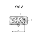
- FIG. 2 shows only the mouthpiece because the extruder has a conventional structure. Specifically, as shown in a sectional view in the widthwise direction of the mouthpiece 9 in FIG.
- the mouthpiece 9 has an opening width which allows plural metal filaments 1 to be introduced to the mouthpiece 9 from the inlet side thereof in a manner that the metal filaments 1 are juxtaposed within the mouthpiece 9, so that the peripheries of the metal filaments 1 are coated with these rubber 3 at a time and extruded as metal filaments 1a together with the rubber 3.
- the respective metal filaments 1 are preferably juxtaposed by using a guide prior to introduction thereof to the mouthpiece 9.
- the metal filaments 1a By juxtaposing the metal filaments 1 within the mouthpiece 9, coating the metal filaments 1 with rubber 3 and extruding the metal filaments 1a coated with rubber 3 as described above, the metal filaments 1a can be linearly supplied along a pass line linking the rubber coating apparatus 2 and the filament twisting machine 7 when the metal filaments 1a are supplied to the filament twisting machine 7, whereby the metal filaments 1a can be prevented from making contact with the guide 5. As a result, since contact of the metal filament 1a with the guide 5 is prevented, the rubber 3 does not come off from the metal filament 1a, whereby the metal filaments 1a each reliably coated with rubber can be supplied to the filament twisting machine 7.
- metal filaments 1 a travel without making contact with the guide 5, it is very unlikely that rubber which has come off from the metal filaments 1a clogs a through hole of the guide. Accordingly, a situation in which the rubber 3 clogs the through hole of the guide 5 such that the metal filaments 1a can no longer pass through the through hole of the guide 5 can be prevented from occurring.
- the metal filaments 1a are supplied to the filament twisting machine 7 via the twist-eliminating machine 4 for eliminating twist transmitted from the filament twisting machine 7, in particular, a buncher twisting machine to the respective metal filaments 1a, and the metal filaments 1a are twisted to produce a cord 8 by the filament twisting machine 7, whereby a cord inside of which is reliably filled with rubber can be produced.
- the metal filaments 1 are not twisted with each other when the metal filaments 6 are coated with rubber 3 within the mouthpiece 9.
- the metal filaments can be coated with rubber 3 without entangling with each other to create a closed space at the core thereof.
- the peripheries of the respective metal filaments 1 can be each reliably coated with the rubber 3, whereby, for example, in a case where a cord having 1 ⁇ 3 structure is produced by using three metal filaments, the three metal filaments are coated with rubber in advance and thus a cord of which center portions between the filaments are sufficiently permeated with rubber can be produced. Accordingly, growth of corrosion by moisture described above is suppressed and thus a cord having excellent durability can be produced.
- the filament twisting machine used for twisting the metal filaments 1a each other in the cord production is a buncher-type machine
- twist is inevitably generated in the metal filaments and thus application of the present invention is especially effective.
- the cord produced as described above will be a cord having a twisted single layered structure such as 1 ⁇ n (n ⁇ 3).
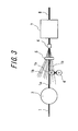
- another cord according to the present invention can be produced as shown in FIG. 3 by: introducing plural (nine in the drawing) filaments 1b, which are to form a sheath, to the periphery of the aforementioned metal filaments 1a coated with rubber and then to the guide 5; converging the metal filaments 1a and the metal filaments 1b in the converting portion 6; and then twisting the metal filaments 1a and the metal filaments 1b with each other simultaneously by the filament twisting machine 7, to produce a cord having a single twist double layered structure.
- a cord structure where the inside of the core thereof is completely filled with rubber without voids can be realized by using the aforementioned metal filaments 1a as the core of a cord of a single twist double layered structure.
- the apparatus for coating plural metal filaments 1 with rubber 3 includes an extruder and a mouthpiece 9 as described above. It is essential that the mouthpiece 9 has a width which allows plural metal filaments 1 to be disposed in a juxtaposed manner in the mouthpiece 9.
- plural metal filaments 1 can be juxtaposed within the mouthpiece 9 and thus these metal filaments 1 can be coated with rubber 3 at a time because the mouthpiece 9 has a width which allows the plural metal filaments 1 can be disposed in a juxtaposed manner therein.
- the metal filaments 1 can avoid making contact with the guide 5 and thus a situation in which the rubber 3 comes off from the metal filaments 1a can be prevented from occurring.
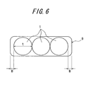
- the mouthpiece 9 in which plural metal filaments 1 can be disposed in a juxtaposed manner preferably has a width W calculated by formula (1) below.
- "A” in the formula (1) is a value calculated by formula (2) below in consideration B shown in FIG. 6 .
- Width W mm diameter t mm of metal filament ⁇ number of metal filament to be coated with rubber ⁇ 1 + t ⁇ A and (A is preferably equal to or larger than 1.2)
- each respective metal filament 1 is coated with rubber 3 in a state where the metal filament is not twisted in the process of coating the metal filament 1 with rubber 3 by the rubber coating apparatus 2, whereby coating with rubber can be effected in a reliable and stable manner.
- the twist-eliminating machine 4 for eliminating twist transmitted from the filament twisting machine 7 to the metal filaments can eliminate twist from the filament twisting machine 7 as long as the machine 4 is provided between the outlet side of the rubber coating apparatus 2 and the guide 5. Therefore, the disposition of the twist-eliminating machine 4 is not restricted to the position shown in FIG. 1 or FIG. 3 .
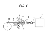
- multiple groove pulleys as shown in FIG. 4 can be used. Specifically, transmission of twist can be eliminated by making the metal filaments go through a vertical pair of multiple groove pulleys each having multiple grooves plural times.
- Cords each having 3 + 9 ⁇ 022 (mm) structure were produced by using mouthpieces having widths calculated by substituting the A values shown in Table 1 for A in formula (1), respectively, by the cord producing process as show in FIG. 3 , which process includes juxtaposing three metal filaments, coating the metal filaments with rubber and twisting nine metal filaments, which were to form a sheath, around the three metal filaments.
- Each of the cords thus obtained was evaluated for permeation properties of rubber. The results are shown in Table 1.
- the metal filaments constituting the cord were coated with rubber by the conventional rubber coating method.
- Permeation properties of rubber were evaluated by observing a rubber-coated area in a section of each cord cut in a direction orthogonal to the axial direction thereof.
Landscapes
- Engineering & Computer Science (AREA)
- Mechanical Engineering (AREA)
- Textile Engineering (AREA)
- Ropes Or Cables (AREA)
- Extrusion Moulding Of Plastics Or The Like (AREA)
- Tyre Moulding (AREA)
Abstract
Description
- The present invention relates to a method of coating a metal filament as a constituent of, for example, a cord for reinforcing a rubber article, with rubber, a method of producing a cord by twisting metal filaments as constituents of a cord by a filament twisting machine, a cord formed by twisting rubber-coated metal filaments by a filament twisting machine, a rubber coating apparatus for coating a metal filament with rubber, and a cord producing apparatus.
- Various characteristics are required of a cord for reinforcing a rubber article, in particular, a cord serving for reinforcing a tire. A cord for reinforcing a tire is required, above all, to be capable of suppressing deterioration of cord durability, which deterioration is due to growth of corrosion caused by moisture which has entered inside the tire.
- Specifically, when moisture enters the inside of a tire from an external damage of the tire and the moisture reaches a cord, the cord suffers from corrosion due to the moisture. In this situation, if there exists a clearance inside the cord, the moisture travels in the longitudinal direction of the cord via the clearance, thereby enlarging a corrosion area along the cord. As a result, durability of the cord deteriorates due to this corrosion.
- Accordingly, in order to suppress corrosion of a cord, it is necessary to sufficiently fill a clearance inside the cord with rubber and prevent moisture from travelling along the longitudinal direction of the cord.
- In view of this,
JP 2002-302884 JP 2002-302885 - Further,
JP 2002-266266 - However, in the technologies disclosed in
JP 2002-302884 JP 2002-302885 - Further, in the case of the technology of
JP 2002-266266 - In view of the problems above, an object of the present invention is to make it possible to provide a cord, in particular, a cord for reinforcing a rubber article in which rubber permeation properties are improved by coating filaments as constituents of the cord with rubber in a reliable and stable manner.
- As a result of a keen study of means for achieving the aforementioned object, the inventors of the present invention have discovered that filaments can be coated with rubber in a reliable and stable manner by laying the filaments horizontally and coating these filaments with rubber at a time when the filaments are coated with rubber and suppressing twisting of the filaments originated by a twisting machine when the filaments are twisted to a cord, to complete the present invention.
- Specifically, the gist of the present invention is as follows: (1) a method of coating a metal filament with rubber, characterized in that, when the metal filament is guided to an extruder and extruded together with rubber from a mouthpiece of the extruder so that the metal filament is coated with the rubber, plural metal filaments are juxtaposed in the mouthpiece and extruded together with rubber;
- (2) a method of producing a cord, characterized in that, when a metal filament is guided to an extruder and plural metal filaments are juxtaposed in a mouthpiece of the extruder and extruded together with rubber from the mouthpiece and then the plural metal filaments thus coated with rubber are supplied to a filament twisting machine to produce a cord, a twist transmitted from the filament twisting machine to the metal filaments thus coated with rubber is eliminated on the outlet side of the mouthpiece;
- (3) a method of producing a cord of (2) above, wherein the filament twisting machine is a buncher type machine;
- (4) a cord having a twisted single-layered structure, formed by twisting plural metal filaments coated with rubber by the method described of (1) above;
- (5) a cord having a single twist double layered structure, formed by arranging plural metal filaments as a sheath around plural metal filaments as a core coated with rubber by the method of (1) above and twisting the core and the sheath simultaneously;
- (6) a cord having a double twist double layered structure, formed by twisting plural metal filaments as a sheath around the cord as a core produced by the method of (2);
- (7) a rubber coating apparatus including an extruder and a mouthpiece, characterized in that the mouthpiece has a width which allows plural metal filaments to be arranged in a juxtaposed manner.
- (8) a cord producing apparatus including the rubber coating apparatus as described in (7) above and a filament twisting machine, characterized in that it further includes a twist-eliminating machine disposed on the outlet side of the rubber coating apparatus, for eliminating a twist transmitted from the filament twisting machine to a metal filament.
- (9) the cord producing apparatus of (8) above, wherein the twist-eliminating machine is a multiple groove pulley system.
- According to the present invention, plural metal filaments can be coated with rubber in a reliable and stable manner by juxtaposing plural metal filaments in a mouthpiece of an extruder and coating these juxtaposed metal filaments with rubber at a time. As a result, the metal filaments can be twisted to form a cord without experiencing the rubber peeling off therefrom. Further, twisting of a metal filament can be suppressed by eliminating on the outlet side of the mouthpiece a twist transmitted from a filament twisting machine to the metal filament, whereby the filament can be coated with rubber in a reliable and stable manner. As a result, a cord having excellent durability can be obtained.
-
FIG. 1 is a view showing a method of producing a cord according to the present invention. -
FIG. 2 is a view showing a section in the widthwise direction of a mouthpiece. -
FIG. 3 is a view showing a method of producing a cord having a single twist double layered structure. -
FIG. 4 is a view showing a method of producing a cord having a double twist double layered structure. -
FIG. 5 is a view showing multiple groove pulleys. -
FIG. 6 is a view showing clearances between metal filaments and the mouthpiece. Explanation of Reference Numerals -
- 1
- Metal filament
- 1a
- Metal filament coated with rubber
- 1b
- Metal filament which is to form sheath
- 2
- Rubber coating apparatus
- 3
- Rubber
- 4
- Twist eliminating apparatus
- 5
- Guide
- 6
- Converging portion
- 7
- Filament twisting machine
- 8
- Cord
- 9
- Mouthpiece
- 10
- Multiple groove pulley
- 11
- Spool
- The present invention will be described in detail hereinafter. A method of coating metal filaments with rubber of the present invention will be described with reference to the drawings. First,
FIG. 1 shows a process of twisting metal filaments to produce a cord. InFIG. 1 , plural (three in the drawing)metal filaments 1 are supplied to arubber coating apparatus 2 so that themetal filaments 1 are coated withrubber 3, and themetal filaments 1a coated withrubber 3 are made to pass through aguide 5 via a twist-eliminatingmachine 4. Themetal filaments 1a are then converted by a convergingportion 6, supplied to afilament twisting machine 7 and twisted by thefilament twisting machine 7, whereby acord 8 is produced. - Herein, a process of coating the
metal filament 1 with rubber will be described in detail with reference toFIG. 2 . Therubber coating apparatus 2 has an extruder for simultaneously extruding themetal filaments 1 introduced thereto and rubber, and a mouthpiece for restricting a configuration of extrusion.FIG. 2 shows only the mouthpiece because the extruder has a conventional structure. Specifically, as shown in a sectional view in the widthwise direction of themouthpiece 9 inFIG. 2 , themouthpiece 9 has an opening width which allowsplural metal filaments 1 to be introduced to themouthpiece 9 from the inlet side thereof in a manner that themetal filaments 1 are juxtaposed within themouthpiece 9, so that the peripheries of themetal filaments 1 are coated with theserubber 3 at a time and extruded asmetal filaments 1a together with therubber 3. In the present embodiment, in order to juxtapose themetal filaments 1 within themouthpiece 9 for introduction thereof to themouthpiece 9, therespective metal filaments 1 are preferably juxtaposed by using a guide prior to introduction thereof to themouthpiece 9. - By juxtaposing the
metal filaments 1 within themouthpiece 9, coating themetal filaments 1 withrubber 3 and extruding themetal filaments 1a coated withrubber 3 as described above, themetal filaments 1a can be linearly supplied along a pass line linking therubber coating apparatus 2 and thefilament twisting machine 7 when themetal filaments 1a are supplied to thefilament twisting machine 7, whereby themetal filaments 1a can be prevented from making contact with theguide 5. As a result, since contact of themetal filament 1a with theguide 5 is prevented, therubber 3 does not come off from themetal filament 1a, whereby themetal filaments 1a each reliably coated with rubber can be supplied to thefilament twisting machine 7. - Further, since
metal filaments 1 a travel without making contact with theguide 5, it is very unlikely that rubber which has come off from themetal filaments 1a clogs a through hole of the guide. Accordingly, a situation in which therubber 3 clogs the through hole of theguide 5 such that themetal filaments 1a can no longer pass through the through hole of theguide 5 can be prevented from occurring. - Next, a procedure for producing a cord by twisting the
metal filaments 1a coated with rubber according to the aforementioned method will be described. First,plural metal filaments 1 are juxtaposed in themouthpiece 9 and extruded together with rubber. It is important that, when themetal filaments 1a are supplied to thefilament twisting machine 7 to produce a cord, twist transmitted from thefilament twisting machine 7 to themetal filament 1a is eliminated on the outlet side of themouthpiece 9. Specifically, themetal filaments 1a are supplied to thefilament twisting machine 7 via the twist-eliminatingmachine 4 for eliminating twist transmitted from thefilament twisting machine 7, in particular, a buncher twisting machine to therespective metal filaments 1a, and themetal filaments 1a are twisted to produce acord 8 by thefilament twisting machine 7, whereby a cord inside of which is reliably filled with rubber can be produced. - Since twist transmitted from the
filament twisting machine 7 to the metal filaments is eliminated, themetal filaments 1 are not twisted with each other when themetal filaments 6 are coated withrubber 3 within themouthpiece 9. In other words, the metal filaments can be coated withrubber 3 without entangling with each other to create a closed space at the core thereof. As a result, the peripheries of therespective metal filaments 1 can be each reliably coated with therubber 3, whereby, for example, in a case where a cord having 1 × 3 structure is produced by using three metal filaments, the three metal filaments are coated with rubber in advance and thus a cord of which center portions between the filaments are sufficiently permeated with rubber can be produced. Accordingly, growth of corrosion by moisture described above is suppressed and thus a cord having excellent durability can be produced. - In the present embodiment, in a case where the filament twisting machine used for twisting the
metal filaments 1a each other in the cord production is a buncher-type machine, twist is inevitably generated in the metal filaments and thus application of the present invention is especially effective. The cord produced as described above will be a cord having a twisted single layered structure such as 1 × n (n≥3). - Further, another cord according to the present invention can be produced as shown in
FIG. 3 by: introducing plural (nine in the drawing)filaments 1b, which are to form a sheath, to the periphery of theaforementioned metal filaments 1a coated with rubber and then to theguide 5; converging themetal filaments 1a and themetal filaments 1b in the convertingportion 6; and then twisting themetal filaments 1a and themetal filaments 1b with each other simultaneously by thefilament twisting machine 7, to produce a cord having a single twist double layered structure. - In short, in a case of a cord having a double layered structure, a cord structure where the inside of the core thereof is completely filled with rubber without voids can be realized by using the
aforementioned metal filaments 1a as the core of a cord of a single twist double layered structure. - Further, it is acceptable to once wind up a cord produced by a series of processes as shown in
FIG. 1 on a spool, and in the process shown inFIG. 4 , take the cord thus wound up on thespool 11 out of thespool 11, feed the cord to the twist-eliminatingapparatus 4, then pass the cord through theguide 5, converge the metal filaments, which are to form a sheath, around thecord 8 in the convergingportion 6, and twist the cord and the metal filaments by thefilament twisting machine 7 to produce a cord having a double twist double layered structure using the cord wound up by thespool 11 as the core. The cord thus twisted may be pulled out of thefilament twisting machine 7 and then wound up on a spool, or wound up on a spool inside thefilament twisting machine 7. - The apparatus for coating
plural metal filaments 1 withrubber 3 includes an extruder and amouthpiece 9 as described above. It is essential that themouthpiece 9 has a width which allowsplural metal filaments 1 to be disposed in a juxtaposed manner in themouthpiece 9. - Specifically,
plural metal filaments 1 can be juxtaposed within themouthpiece 9 and thus thesemetal filaments 1 can be coated withrubber 3 at a time because themouthpiece 9 has a width which allows theplural metal filaments 1 can be disposed in a juxtaposed manner therein. As a result, themetal filaments 1 can avoid making contact with theguide 5 and thus a situation in which therubber 3 comes off from themetal filaments 1a can be prevented from occurring. - In the present embodiment, the
mouthpiece 9 in whichplural metal filaments 1 can be disposed in a juxtaposed manner preferably has a width W calculated by formula (1) below. "A" in the formula (1) is a value calculated by formula (2) below in consideration B shown inFIG. 6 .
Note:
(A is preferably equal to or larger than 1.2) - Further, its is important to provide, on the outlet side of the
rubber coating apparatus 2, the twist-eliminatingmachine 4 for eliminating transmission of twist from thefilament twisting machine 7 in a cord producing apparatus including therubber coating apparatus 2, having the extruder and the mouthpiece, and thefilament twisting machine 7. Twist transmitted from thefilament twisting machine 7 to the metal filaments can be eliminated by providing on the outlet side of therubber coating apparatus 2 the twist-eliminatingmachine 4 for eliminating transmission of twist. As a result, eachrespective metal filament 1 is coated withrubber 3 in a state where the metal filament is not twisted in the process of coating themetal filament 1 withrubber 3 by therubber coating apparatus 2, whereby coating with rubber can be effected in a reliable and stable manner. - The twist-eliminating
machine 4 for eliminating twist transmitted from thefilament twisting machine 7 to the metal filaments can eliminate twist from thefilament twisting machine 7 as long as themachine 4 is provided between the outlet side of therubber coating apparatus 2 and theguide 5. Therefore, the disposition of the twist-eliminatingmachine 4 is not restricted to the position shown inFIG. 1 orFIG. 3 . - As the twist-eliminating machine as described above, multiple groove pulleys as shown in
FIG. 4 can be used. Specifically, transmission of twist can be eliminated by making the metal filaments go through a vertical pair of multiple groove pulleys each having multiple grooves plural times. - Cords each having 3 + 9×022 (mm) structure were produced by using mouthpieces having widths calculated by substituting the A values shown in Table 1 for A in formula (1), respectively, by the cord producing process as show in
FIG. 3 , which process includes juxtaposing three metal filaments, coating the metal filaments with rubber and twisting nine metal filaments, which were to form a sheath, around the three metal filaments. Each of the cords thus obtained was evaluated for permeation properties of rubber. The results are shown in Table 1. Regarding a cord of Conventional Example, the metal filaments constituting the cord were coated with rubber by the conventional rubber coating method. - Permeation properties of rubber were evaluated by observing a rubber-coated area in a section of each cord cut in a direction orthogonal to the axial direction thereof.
-
[Table 1] Conventional Example Present Example 1 Present Example 2 Present Example 3 Value of A - 1.08 1.20 1.32 Width W (mm) - 0.678 0.704 0.730 Permeation of rubber 15 67 82 98 - From the results of Table 1, it is understood that permeation properties of rubber of the cords of Present Examples significantly improve as compared with those of Conventional Example.
Claims (9)
- A method of coating a metal filament with rubber, characterized in that, when the metal filament is guided to an extruder and extruded together with rubber from a mouthpiece of the extruder so that the metal filament is coated with the rubber, plural metal filaments are juxtaposed in the mouthpiece and extruded together with rubber.
- A method of producing a cord, characterized in that, when a metal filament is guided to an extruder and plural metal filaments are juxtaposed in a mouthpiece of the extruder and extruded together with rubber from the mouthpiece and then the plural metal filaments thus coated with rubber are supplied to a filament twisting machine to produce a cord, a twist transmitted from the filament twisting machine to the metal filaments thus coated with rubber is eliminated on the outlet side of the mouthpiece.
- The method of producing a cord of claim 2, wherein the filament twisting machine is a buncher type machine.
- A cord having a twisted single-layered twisted structure, formed by twisting plural metal filaments coated with rubber by the method of claim 1.
- A cord having a single twist double layered structure, formed by arranging plural metal filaments as a sheath around plural metal filaments coated with rubber by the method of claim 1 as a core and twisting the core and the sheath simultaneously;
- A cord having a double twist double layered structure, formed by twisting plural metal filaments as a sheath around the cord as a core produced by the method of claim 2.
- A rubber coating apparatus including an extruder and a mouthpiece, characterized in that the mouthpiece has a width which allows plural metal filaments to be arranged in a juxtaposed manner.
- A cord producing apparatus including the rubber coating apparatus of claim 7 and a filament twisting machine, characterized in that it further includes a twist-eliminating machine disposed on the outlet side of the rubber coating apparatus, for eliminating a twist transmitted from the filament twisting machine to a metal filament.
- The cord producing apparatus of claim 8, wherein the twist-eliminating machine is a multiple groove pulley system.
Applications Claiming Priority (2)
| Application Number | Priority Date | Filing Date | Title |
|---|---|---|---|
| JP2007243968A JP4925986B2 (en) | 2007-09-20 | 2007-09-20 | Rubber coating method for metal wire, cord manufacturing method, cord, rubber coating device, and cord manufacturing device |
| PCT/JP2008/067008 WO2009038188A1 (en) | 2007-09-20 | 2008-09-19 | Rubber coating method for metallic element wire, cord manufacturing method, cord, rubber coating apparatus, and cord manufacturing apparatus |
Publications (3)
| Publication Number | Publication Date |
|---|---|
| EP2202045A1 true EP2202045A1 (en) | 2010-06-30 |
| EP2202045A4 EP2202045A4 (en) | 2014-03-26 |
| EP2202045B1 EP2202045B1 (en) | 2016-01-06 |
Family
ID=40467997
Family Applications (1)
| Application Number | Title | Priority Date | Filing Date |
|---|---|---|---|
| EP08832452.0A Not-in-force EP2202045B1 (en) | 2007-09-20 | 2008-09-19 | Cord manufacturing method and apparatus |
Country Status (5)
| Country | Link |
|---|---|
| US (2) | US9003849B2 (en) |
| EP (1) | EP2202045B1 (en) |
| JP (1) | JP4925986B2 (en) |
| CN (1) | CN101835589B (en) |
| WO (1) | WO2009038188A1 (en) |
Cited By (2)
| Publication number | Priority date | Publication date | Assignee | Title |
|---|---|---|---|---|
| WO2015031226A1 (en) * | 2013-08-28 | 2015-03-05 | E. I. Du Pont De Nemours And Company | Fibrous cord and method of making |
| CN110546019A (en) * | 2017-04-06 | 2019-12-06 | 株式会社普利司通 | Resin-metal composite member for tire and tire |
Families Citing this family (5)
| Publication number | Priority date | Publication date | Assignee | Title |
|---|---|---|---|---|
| JP5647082B2 (en) * | 2011-08-18 | 2014-12-24 | 住友ゴム工業株式会社 | Manufacturing method of steel cord band for rubber track |
| DE102014211929A1 (en) | 2014-06-23 | 2016-01-07 | ContiTech Transportsysteme GmbH | Method for producing a tension member in rope construction, in particular for conveyor belts |
| CN106868901A (en) * | 2016-12-28 | 2017-06-20 | 柳州欧维姆机械股份有限公司 | A kind of method that anti-corrosion material is filled in gap to bridge steel silk drag-line |
| CN106948197B (en) * | 2017-04-01 | 2023-01-03 | 东台磊达钢帘线有限公司 | Cord forming control device |
| JP6610734B1 (en) | 2018-08-23 | 2019-11-27 | 横浜ゴム株式会社 | Method and apparatus for manufacturing rubber-coated cord |
Family Cites Families (33)
| Publication number | Priority date | Publication date | Assignee | Title |
|---|---|---|---|---|
| US885219A (en) * | 1907-04-25 | 1908-04-21 | Eugene D C Bayne | Fabric. |
| US2040105A (en) * | 1934-02-13 | 1936-05-12 | Dayton Rubber Mfg Co | Process and apparatus for latexing cords |
| US2131981A (en) * | 1934-03-21 | 1938-10-04 | Shepherd Thomas Lewis | Elastic or rubber thread or yarn and method of manufacturing the same |
| US2105812A (en) * | 1935-08-29 | 1938-01-18 | Wingfoot Corp | Bead wire die |
| US2601394A (en) * | 1947-02-01 | 1952-06-24 | Goodrich Co B F | Apparatus for impregnating cord |
| US2563113A (en) * | 1948-04-13 | 1951-08-07 | Us Rubber Co | Method of bonding rubber to metals |
| US3143786A (en) * | 1961-01-27 | 1964-08-11 | Vaughn Machinery Co | Bar and wire processing machine |
| US3538699A (en) * | 1969-02-28 | 1970-11-10 | Owens Corning Fiberglass Corp | Method and apparatus for controlling delivery of filamentary material to rotatable collectors |
| US3682222A (en) * | 1970-01-06 | 1972-08-08 | Steelastic Co | Pneumatic tire having helical reinforcing filaments |
| US3908351A (en) * | 1973-12-27 | 1975-09-30 | Ppg Industries Inc | Novel tire cord forming process |
| JPS5233087A (en) * | 1975-09-09 | 1977-03-12 | Daiden Kk | Method to manufacture a self support type cable with a twist |
| JPS5351804A (en) | 1976-10-19 | 1978-05-11 | Kobe Steel Ltd | Bead for tire |
| US4143209A (en) * | 1977-06-07 | 1979-03-06 | The Goodyear Tire & Rubber Company | Process for making zinc coated steel wire and product made thereby |
| US4277642A (en) * | 1978-09-15 | 1981-07-07 | Western Electric Company, Inc. | Cordage having a plurality of conductors in a partitioned jacket |
| US4274821A (en) * | 1980-02-28 | 1981-06-23 | The Steelastic Company | Die for extruding reinforced fabric |
| US4471527A (en) * | 1981-11-05 | 1984-09-18 | Yazaki Corporation | Method and apparatus for the production of stranded cable |
| JPS5881151A (en) * | 1981-11-09 | 1983-05-16 | Bridgestone Corp | Manufacture of carcass band of radial tire |
| EP0375896B1 (en) | 1988-12-28 | 1994-06-01 | Ube-Nitto Kasei Co. Ltd. | Twisted FRP structure and process for manufacturing the same |
| CA2097642A1 (en) * | 1993-03-19 | 1994-09-20 | Jerry Malin | Method and apparatus for fabricating a rubberized wire sheet |
| JPH08103972A (en) * | 1994-08-10 | 1996-04-23 | Sumitomo Rubber Ind Ltd | Code topping method |
| JPH09137392A (en) | 1995-01-30 | 1997-05-27 | Sumitomo Electric Ind Ltd | Metal cord, its manufacturing method, and rubber composite using the cord |
| JP4615706B2 (en) * | 1999-12-27 | 2011-01-19 | 不二精工株式会社 | Twisted wire untwisting device, rubber-coated stranded wire manufacturing apparatus, and rubber-coated stranded wire manufacturing method |
| KR20020005595A (en) | 1999-12-27 | 2002-01-17 | 다카기 시게마사 | Rubber coated strands, belt, ply, and tire using rubber coated strands and apparatus and method for manufacturing them |
| JP4487363B2 (en) * | 2000-02-23 | 2010-06-23 | 横浜ゴム株式会社 | Method and apparatus for producing unvulcanized rubber / steel wire composite |
| JP2002266266A (en) | 2001-03-13 | 2002-09-18 | Yokohama Rubber Co Ltd:The | Method of manufacturing elastomer composite steel cord |
| DE10213289A1 (en) | 2001-03-30 | 2002-11-14 | Yokohama Rubber Co Ltd | Elastomer and steel cord composite and process for making the same |
| JP4355111B2 (en) | 2001-03-30 | 2009-10-28 | 横浜ゴム株式会社 | Manufacturing method of elastomer composite steel cord |
| JP2002302884A (en) | 2001-03-30 | 2002-10-18 | Yokohama Rubber Co Ltd:The | Method of manufacturing elastomer composite steel cord |
| US7056110B2 (en) * | 2001-10-08 | 2006-06-06 | Bridgestone/Firestone North American Tire, Llc | Apparatus for making reinforcement ply material |
| WO2004048679A1 (en) | 2002-11-25 | 2004-06-10 | Bridgestone Corporation | Twisting machine, twisted wire manufacturing method, ply, and pneumatic tire |
| JP4316904B2 (en) | 2003-03-14 | 2009-08-19 | 不二精工株式会社 | Rubber coated steel cord manufacturing apparatus, cord, rubber ribbon using the cord, and tire manufacturing method using the same |
| JP2005193494A (en) * | 2004-01-06 | 2005-07-21 | Toyo Tire & Rubber Co Ltd | Die insert for extruder |
| JP4611790B2 (en) | 2005-04-14 | 2011-01-12 | 株式会社ブリヂストン | Twisted wire machine and method for coating twisted wire |
-
2007
- 2007-09-20 JP JP2007243968A patent/JP4925986B2/en not_active Expired - Fee Related
-
2008
- 2008-09-19 EP EP08832452.0A patent/EP2202045B1/en not_active Not-in-force
- 2008-09-19 US US12/679,136 patent/US9003849B2/en not_active Expired - Fee Related
- 2008-09-19 CN CN200880113218.0A patent/CN101835589B/en not_active Expired - Fee Related
- 2008-09-19 WO PCT/JP2008/067008 patent/WO2009038188A1/en not_active Ceased
-
2013
- 2013-03-29 US US13/853,611 patent/US9109306B2/en active Active
Cited By (2)
| Publication number | Priority date | Publication date | Assignee | Title |
|---|---|---|---|---|
| WO2015031226A1 (en) * | 2013-08-28 | 2015-03-05 | E. I. Du Pont De Nemours And Company | Fibrous cord and method of making |
| CN110546019A (en) * | 2017-04-06 | 2019-12-06 | 株式会社普利司通 | Resin-metal composite member for tire and tire |
Also Published As
| Publication number | Publication date |
|---|---|
| CN101835589A (en) | 2010-09-15 |
| EP2202045B1 (en) | 2016-01-06 |
| JP2009073029A (en) | 2009-04-09 |
| US20130219850A1 (en) | 2013-08-29 |
| US9109306B2 (en) | 2015-08-18 |
| EP2202045A4 (en) | 2014-03-26 |
| WO2009038188A1 (en) | 2009-03-26 |
| CN101835589B (en) | 2014-01-15 |
| US9003849B2 (en) | 2015-04-14 |
| JP4925986B2 (en) | 2012-05-09 |
| US20100203330A1 (en) | 2010-08-12 |
Similar Documents
| Publication | Publication Date | Title |
|---|---|---|
| US9109306B2 (en) | Method of coating metal filament with rubber, method of producing cord, cord, rubber coating apparatus and cord producing apparatus | |
| EP0383716A1 (en) | Metal wire cord for elastomer reinforcement | |
| US11139090B1 (en) | Electrical cables with non-metallic jackets and methods of fabricating the same | |
| US20030106300A1 (en) | Zinc-coated steel cord with improved fatigue resistance | |
| CN101802297A (en) | Cord, process for producing the same, and composite of cord with rubber | |
| WO2012009604A3 (en) | Composite cord and method of making and support structure for a tire containing same | |
| US10105991B2 (en) | Steel cord for reinforcing rubber article, and pneumatic tire using same | |
| DE112011102189T5 (en) | tire | |
| US8826945B1 (en) | Apparatus and method for forming wire | |
| JP2002302885A (en) | Method of manufacturing elastomer composite steel cord | |
| EP3543399A1 (en) | Steel cord for reinforcing rubber articles and rubber crawler and tire using same | |
| CN108320843A (en) | A kind of reel suspender private cable and production method | |
| US6182433B1 (en) | Steel cords for the reinforcement of rubber articles | |
| DE60122063T2 (en) | METHOD AND DEVICE FOR PRODUCTION OF UNPULCANIZED RUBBER / STEEL WIRE | |
| US20030096095A1 (en) | Reinforced ply material with untwisted sets of steel monofilaments | |
| CN101311409A (en) | Manufacturing method of steel cord and steel cord | |
| JP4361638B2 (en) | Steel cord manufacturing method and stranded wire machine used in this method | |
| KR100366069B1 (en) | Steel cord for reinforcing tire and its production method | |
| CN115240921B (en) | Semicircular cable core and preparation method of communication cable | |
| US20170036385A1 (en) | Apparatus and method for formation of separator and casing for multi conductor wire in a single operation | |
| JPH06108387A (en) | Steel cord for reinforcing rubber articles and method for manufacturing the same | |
| CN217719147U (en) | Production line of semicircle cable core | |
| CN121477419A (en) | Natural styrene-butadiene sheath vulcanization method for stranded optical cables and its application in the manufacture of composite cables | |
| DE112023006284T5 (en) | CABLE | |
| JP2001181989A (en) | Non-twisted steel cord and method for producing the same |
Legal Events
| Date | Code | Title | Description |
|---|---|---|---|
| PUAI | Public reference made under article 153(3) epc to a published international application that has entered the european phase |
Free format text: ORIGINAL CODE: 0009012 |
|
| 17P | Request for examination filed |
Effective date: 20100325 |
|
| AK | Designated contracting states |
Kind code of ref document: A1 Designated state(s): AT BE BG CH CY CZ DE DK EE ES FI FR GB GR HR HU IE IS IT LI LT LU LV MC MT NL NO PL PT RO SE SI SK TR |
|
| AX | Request for extension of the european patent |
Extension state: AL BA MK RS |
|
| DAX | Request for extension of the european patent (deleted) | ||
| A4 | Supplementary search report drawn up and despatched |
Effective date: 20140224 |
|
| RIC1 | Information provided on ipc code assigned before grant |
Ipc: B29C 47/08 20060101ALN20140218BHEP Ipc: B29C 47/28 20060101ALN20140218BHEP Ipc: D07B 7/08 20060101ALI20140218BHEP Ipc: B29D 30/38 20060101ALI20140218BHEP Ipc: B29C 47/02 20060101AFI20140218BHEP |
|
| 17Q | First examination report despatched |
Effective date: 20140918 |
|
| GRAP | Despatch of communication of intention to grant a patent |
Free format text: ORIGINAL CODE: EPIDOSNIGR1 |
|
| RIC1 | Information provided on ipc code assigned before grant |
Ipc: B29C 47/08 20060101ALN20150618BHEP Ipc: D07B 7/08 20060101ALI20150618BHEP Ipc: B29C 47/02 20060101AFI20150618BHEP Ipc: B29D 30/38 20060101ALI20150618BHEP Ipc: B29C 47/28 20060101ALN20150618BHEP |
|
| INTG | Intention to grant announced |
Effective date: 20150706 |
|
| GRAS | Grant fee paid |
Free format text: ORIGINAL CODE: EPIDOSNIGR3 |
|
| GRAA | (expected) grant |
Free format text: ORIGINAL CODE: 0009210 |
|
| AK | Designated contracting states |
Kind code of ref document: B1 Designated state(s): AT BE BG CH CY CZ DE DK EE ES FI FR GB GR HR HU IE IS IT LI LT LU LV MC MT NL NO PL PT RO SE SI SK TR |
|
| REG | Reference to a national code |
Ref country code: GB Ref legal event code: FG4D |
|
| REG | Reference to a national code |
Ref country code: CH Ref legal event code: EP |
|
| REG | Reference to a national code |
Ref country code: IE Ref legal event code: FG4D |
|
| REG | Reference to a national code |
Ref country code: AT Ref legal event code: REF Ref document number: 768484 Country of ref document: AT Kind code of ref document: T Effective date: 20160215 |
|
| REG | Reference to a national code |
Ref country code: DE Ref legal event code: R096 Ref document number: 602008041914 Country of ref document: DE |
|
| REG | Reference to a national code |
Ref country code: LT Ref legal event code: MG4D |
|
| REG | Reference to a national code |
Ref country code: NL Ref legal event code: MP Effective date: 20160106 |
|
| REG | Reference to a national code |
Ref country code: AT Ref legal event code: MK05 Ref document number: 768484 Country of ref document: AT Kind code of ref document: T Effective date: 20160106 |
|
| PG25 | Lapsed in a contracting state [announced via postgrant information from national office to epo] |
Ref country code: NL Free format text: LAPSE BECAUSE OF FAILURE TO SUBMIT A TRANSLATION OF THE DESCRIPTION OR TO PAY THE FEE WITHIN THE PRESCRIBED TIME-LIMIT Effective date: 20160106 |
|
| PG25 | Lapsed in a contracting state [announced via postgrant information from national office to epo] |
Ref country code: NO Free format text: LAPSE BECAUSE OF FAILURE TO SUBMIT A TRANSLATION OF THE DESCRIPTION OR TO PAY THE FEE WITHIN THE PRESCRIBED TIME-LIMIT Effective date: 20160406 Ref country code: GR Free format text: LAPSE BECAUSE OF FAILURE TO SUBMIT A TRANSLATION OF THE DESCRIPTION OR TO PAY THE FEE WITHIN THE PRESCRIBED TIME-LIMIT Effective date: 20160407 Ref country code: ES Free format text: LAPSE BECAUSE OF FAILURE TO SUBMIT A TRANSLATION OF THE DESCRIPTION OR TO PAY THE FEE WITHIN THE PRESCRIBED TIME-LIMIT Effective date: 20160106 Ref country code: FI Free format text: LAPSE BECAUSE OF FAILURE TO SUBMIT A TRANSLATION OF THE DESCRIPTION OR TO PAY THE FEE WITHIN THE PRESCRIBED TIME-LIMIT Effective date: 20160106 Ref country code: HR Free format text: LAPSE BECAUSE OF FAILURE TO SUBMIT A TRANSLATION OF THE DESCRIPTION OR TO PAY THE FEE WITHIN THE PRESCRIBED TIME-LIMIT Effective date: 20160106 |
|
| PG25 | Lapsed in a contracting state [announced via postgrant information from national office to epo] |
Ref country code: LV Free format text: LAPSE BECAUSE OF FAILURE TO SUBMIT A TRANSLATION OF THE DESCRIPTION OR TO PAY THE FEE WITHIN THE PRESCRIBED TIME-LIMIT Effective date: 20160106 Ref country code: LT Free format text: LAPSE BECAUSE OF FAILURE TO SUBMIT A TRANSLATION OF THE DESCRIPTION OR TO PAY THE FEE WITHIN THE PRESCRIBED TIME-LIMIT Effective date: 20160106 Ref country code: PT Free format text: LAPSE BECAUSE OF FAILURE TO SUBMIT A TRANSLATION OF THE DESCRIPTION OR TO PAY THE FEE WITHIN THE PRESCRIBED TIME-LIMIT Effective date: 20160506 Ref country code: IS Free format text: LAPSE BECAUSE OF FAILURE TO SUBMIT A TRANSLATION OF THE DESCRIPTION OR TO PAY THE FEE WITHIN THE PRESCRIBED TIME-LIMIT Effective date: 20160506 Ref country code: SE Free format text: LAPSE BECAUSE OF FAILURE TO SUBMIT A TRANSLATION OF THE DESCRIPTION OR TO PAY THE FEE WITHIN THE PRESCRIBED TIME-LIMIT Effective date: 20160106 Ref country code: AT Free format text: LAPSE BECAUSE OF FAILURE TO SUBMIT A TRANSLATION OF THE DESCRIPTION OR TO PAY THE FEE WITHIN THE PRESCRIBED TIME-LIMIT Effective date: 20160106 Ref country code: PL Free format text: LAPSE BECAUSE OF FAILURE TO SUBMIT A TRANSLATION OF THE DESCRIPTION OR TO PAY THE FEE WITHIN THE PRESCRIBED TIME-LIMIT Effective date: 20160106 |
|
| REG | Reference to a national code |
Ref country code: FR Ref legal event code: PLFP Year of fee payment: 9 |
|
| REG | Reference to a national code |
Ref country code: DE Ref legal event code: R097 Ref document number: 602008041914 Country of ref document: DE |
|
| PG25 | Lapsed in a contracting state [announced via postgrant information from national office to epo] |
Ref country code: EE Free format text: LAPSE BECAUSE OF FAILURE TO SUBMIT A TRANSLATION OF THE DESCRIPTION OR TO PAY THE FEE WITHIN THE PRESCRIBED TIME-LIMIT Effective date: 20160106 Ref country code: DK Free format text: LAPSE BECAUSE OF FAILURE TO SUBMIT A TRANSLATION OF THE DESCRIPTION OR TO PAY THE FEE WITHIN THE PRESCRIBED TIME-LIMIT Effective date: 20160106 |
|
| PGFP | Annual fee paid to national office [announced via postgrant information from national office to epo] |
Ref country code: DE Payment date: 20160921 Year of fee payment: 9 |
|
| PLBE | No opposition filed within time limit |
Free format text: ORIGINAL CODE: 0009261 |
|
| STAA | Information on the status of an ep patent application or granted ep patent |
Free format text: STATUS: NO OPPOSITION FILED WITHIN TIME LIMIT |
|
| PG25 | Lapsed in a contracting state [announced via postgrant information from national office to epo] |
Ref country code: SK Free format text: LAPSE BECAUSE OF FAILURE TO SUBMIT A TRANSLATION OF THE DESCRIPTION OR TO PAY THE FEE WITHIN THE PRESCRIBED TIME-LIMIT Effective date: 20160106 Ref country code: RO Free format text: LAPSE BECAUSE OF FAILURE TO SUBMIT A TRANSLATION OF THE DESCRIPTION OR TO PAY THE FEE WITHIN THE PRESCRIBED TIME-LIMIT Effective date: 20160106 Ref country code: CZ Free format text: LAPSE BECAUSE OF FAILURE TO SUBMIT A TRANSLATION OF THE DESCRIPTION OR TO PAY THE FEE WITHIN THE PRESCRIBED TIME-LIMIT Effective date: 20160106 |
|
| 26N | No opposition filed |
Effective date: 20161007 |
|
| PG25 | Lapsed in a contracting state [announced via postgrant information from national office to epo] |
Ref country code: BE Free format text: LAPSE BECAUSE OF FAILURE TO SUBMIT A TRANSLATION OF THE DESCRIPTION OR TO PAY THE FEE WITHIN THE PRESCRIBED TIME-LIMIT Effective date: 20160106 |
|
| PG25 | Lapsed in a contracting state [announced via postgrant information from national office to epo] |
Ref country code: SI Free format text: LAPSE BECAUSE OF FAILURE TO SUBMIT A TRANSLATION OF THE DESCRIPTION OR TO PAY THE FEE WITHIN THE PRESCRIBED TIME-LIMIT Effective date: 20160106 Ref country code: BG Free format text: LAPSE BECAUSE OF FAILURE TO SUBMIT A TRANSLATION OF THE DESCRIPTION OR TO PAY THE FEE WITHIN THE PRESCRIBED TIME-LIMIT Effective date: 20160406 |
|
| PG25 | Lapsed in a contracting state [announced via postgrant information from national office to epo] |
Ref country code: MC Free format text: LAPSE BECAUSE OF FAILURE TO SUBMIT A TRANSLATION OF THE DESCRIPTION OR TO PAY THE FEE WITHIN THE PRESCRIBED TIME-LIMIT Effective date: 20160106 |
|
| REG | Reference to a national code |
Ref country code: CH Ref legal event code: PL |
|
| GBPC | Gb: european patent ceased through non-payment of renewal fee |
Effective date: 20160919 |
|
| REG | Reference to a national code |
Ref country code: IE Ref legal event code: MM4A |
|
| PG25 | Lapsed in a contracting state [announced via postgrant information from national office to epo] |
Ref country code: IE Free format text: LAPSE BECAUSE OF NON-PAYMENT OF DUE FEES Effective date: 20160919 Ref country code: CH Free format text: LAPSE BECAUSE OF NON-PAYMENT OF DUE FEES Effective date: 20160930 Ref country code: GB Free format text: LAPSE BECAUSE OF NON-PAYMENT OF DUE FEES Effective date: 20160919 Ref country code: LI Free format text: LAPSE BECAUSE OF NON-PAYMENT OF DUE FEES Effective date: 20160930 |
|
| PG25 | Lapsed in a contracting state [announced via postgrant information from national office to epo] |
Ref country code: IT Free format text: LAPSE BECAUSE OF NON-PAYMENT OF DUE FEES Effective date: 20160919 Ref country code: LU Free format text: LAPSE BECAUSE OF NON-PAYMENT OF DUE FEES Effective date: 20160919 |
|
| REG | Reference to a national code |
Ref country code: FR Ref legal event code: PLFP Year of fee payment: 10 |
|
| REG | Reference to a national code |
Ref country code: DE Ref legal event code: R119 Ref document number: 602008041914 Country of ref document: DE |
|
| PG25 | Lapsed in a contracting state [announced via postgrant information from national office to epo] |
Ref country code: HU Free format text: LAPSE BECAUSE OF FAILURE TO SUBMIT A TRANSLATION OF THE DESCRIPTION OR TO PAY THE FEE WITHIN THE PRESCRIBED TIME-LIMIT; INVALID AB INITIO Effective date: 20080919 Ref country code: CY Free format text: LAPSE BECAUSE OF FAILURE TO SUBMIT A TRANSLATION OF THE DESCRIPTION OR TO PAY THE FEE WITHIN THE PRESCRIBED TIME-LIMIT Effective date: 20160106 |
|
| PG25 | Lapsed in a contracting state [announced via postgrant information from national office to epo] |
Ref country code: MT Free format text: LAPSE BECAUSE OF NON-PAYMENT OF DUE FEES Effective date: 20160930 Ref country code: TR Free format text: LAPSE BECAUSE OF FAILURE TO SUBMIT A TRANSLATION OF THE DESCRIPTION OR TO PAY THE FEE WITHIN THE PRESCRIBED TIME-LIMIT Effective date: 20160106 |
|
| PG25 | Lapsed in a contracting state [announced via postgrant information from national office to epo] |
Ref country code: DE Free format text: LAPSE BECAUSE OF NON-PAYMENT OF DUE FEES Effective date: 20180404 |
|
| REG | Reference to a national code |
Ref country code: FR Ref legal event code: PLFP Year of fee payment: 11 |
|
| PGFP | Annual fee paid to national office [announced via postgrant information from national office to epo] |
Ref country code: FR Payment date: 20200914 Year of fee payment: 13 |
|
| PG25 | Lapsed in a contracting state [announced via postgrant information from national office to epo] |
Ref country code: FR Free format text: LAPSE BECAUSE OF NON-PAYMENT OF DUE FEES Effective date: 20210930 |