EP2201592B1 - High flux x-ray target and assembly - Google Patents
High flux x-ray target and assembly Download PDFInfo
- Publication number
- EP2201592B1 EP2201592B1 EP08782363A EP08782363A EP2201592B1 EP 2201592 B1 EP2201592 B1 EP 2201592B1 EP 08782363 A EP08782363 A EP 08782363A EP 08782363 A EP08782363 A EP 08782363A EP 2201592 B1 EP2201592 B1 EP 2201592B1
- Authority
- EP
- European Patent Office
- Prior art keywords
- target
- assembly
- ray
- anode
- oscillatory
- Prior art date
- Legal status (The legal status is an assumption and is not a legal conclusion. Google has not performed a legal analysis and makes no representation as to the accuracy of the status listed.)
- Not-in-force
Links
Images

Classifications
-
- H—ELECTRICITY
- H01—ELECTRIC ELEMENTS
- H01J—ELECTRIC DISCHARGE TUBES OR DISCHARGE LAMPS
- H01J35/00—X-ray tubes
- H01J35/24—Tubes wherein the point of impact of the cathode ray on the anode or anticathode is movable relative to the surface thereof
- H01J35/28—Tubes wherein the point of impact of the cathode ray on the anode or anticathode is movable relative to the surface thereof by vibration, oscillation, reciprocation, or swash-plate motion of the anode or anticathode
Definitions
- This disclosure relates to an X-ray tube assembly and, more particularly, to configuration and structures for controlling heat dissipation and structural loads for an X-ray tube assembly.
- One of the electrodes is an electron emitter cathode which is positioned in the tube in spaced relationship to a target anode.
- Energization of the electrical circuit generates a stream or beam of electrons directed towards the target anode.
- This acceleration is generated from a high voltage differential between the anode and cathode that may range from 60-450 kV, which is a function of the imaging application.
- the electron stream is appropriately focused as a thin beam of very high velocity electrons striking the target anode surface.
- the anode surface ordinarily comprises a predetermined material, for example, a refractory metal so that the kinetic energy of the striking electrons against the target material is converted to electromagnetic waves of very high frequency, i.e. X-rays, which proceed from the target to be collimated and focused for penetration into an object usually for internal examination purposes, for example, industrial inspection procedures, healthcare imaging and treatment, or security imaging applications, food processing industries.
- Imaging applications include, but are not limited to, Radiography, CT, X-ray Diffraction with Cone and Fan beam x-ray fields.
- Well-known primary refractory and non-refractory metals for the anode target surface area exposed to the impinging electron beam include copper (Cu), Fe, Ag, Cr, Co, tungsten (W), molybdenum (Mo), and their alloys for X-ray generation.
- the high velocity beam of electrons impinging the target surface generates extremely high and localized temperatures in the target structure accompanied by high internal stresses leading to deterioration and breakdown of the target structure.
- a rotating anode target generally comprising a shaft supported disk-like structure, one side or face of which is exposed to the electron beam from the thermionic emitter cathode.
- the impinged region of the target is continuously changing to avoid localized heat concentration and stresses and to better distribute the heating effects throughout the structure. Heating remains a major problem in X-ray anode target structures. In a high speed rotating target, heating must be kept within certain proscribed limits to control potentially destructive thermal stresses particularly in composite target structures, as well as to protect low friction, solid lubricated, high precision bearings that support the target.
- US-A-1 997 676 discloses a target electrode supported to have a swinging movement with respect to a cathode element.
- the target electrode is suspended by a flexible resilient strip of steel, copper or the like secured to a suitable terminal block sealed in a head of a tube structure.
- the pendulum movement is initiated by an electromagnet.
- DE 296 22 655 discloses an anode/cathode arrangement in which the anode is arranged to have a reciprocating motion relative to the cathode.
- JP 2001 351551A discloses an X-ray tube that can selectively obtain an X-ray source with a specified characteristic X-ray without changing the X-ray tube.
- the present invention provides an X-ray tube assembly as defined in claim 1 and method for providing heat management to an X-ray assembly as defined in claim 10.
- One set up according to the present disclosure includes an X-ray tube anode assembly having a movable X-ray target having a target surface.
- the anode assembly includes a drive member arranged and disposed to provide oscillatory motion to the target assembly and a target surface that is configured to remain at a substantially fixed distance from a cathode assembly during oscillatory motion.
- an X-ray tube assembly including an envelope having at least a portion thereof substantially transparent to X-ray.
- the assembly also includes a cathode assembly, operatively positioned in the envelope with an anode assembly having a movable X-ray target having a target surface.
- the anode assembly includes a drive member arranged and disposed to provide oscillatory motion to the target assembly and a target surface that is configured to remain at a substantially fixed distance from a cathode assembly during oscillatory motion.
- This anode system may be tuned to allow the pivot to be driven at natural frequency, lowering the required drive power to obtain the desired oscillatory frequency.
- Still another set up according to the present disclosure includes a method for providing heat management to an X-ray assembly.
- the method includes providing an X-ray tube having an envelope having at least a portion thereof substantially transparent to X-ray.
- the assembly also includes a cathode assembly, operatively positioned in the envelope with an anode assembly having a movable X-ray target having a target surface.
- the anode assembly includes a drive member arranged and disposed to provide oscillatory motion to the target assembly and a target surface that is configured to remain at a substantially fixed distance from a cathode assembly during oscillation.
- the method further includes oscillating the anode assembly, wherein the target surface is configured to remain at a substantially fixed distance from the cathode assembly during the oscillating.
- the position of the focal point along the surface of the target is varied, providing improved heat management, wherein the heat may be dissipated more easily.
- the increased dissipation permits the use of higher power and longer durations than are available with the use of a stationary anode arrangement.
- the anode has increased life over anodes that have a fixed focal point on the anode. The oscillatory motion provides longer life than solid lubricated bearings used in known rotating anode sources.
- the assembly will have reduced manufacturing complexity, and cost, in comparison to conventional rotational bearing arrangements.
- the assembly of the present invention provides multiple spots to be placed on a single target, in that each region will be thermally isolated from the neighboring spot, while maintaining the benefit of higher power through oscillatory motion from a single drive mechanism.
- the assembly of the present invention also provides for the introduction of oscillatory motion into an array of focal spots on a multi-spot anode source.
- Set-ups according to the present disclosure also allow the distribution of heat over a larger area of the anode target, through the oscillating motion, which reduces the peak temperature and maintains the temperature below the evaporation limit for the metal in the envelope, and reduces the temperature gradient between surface and substrate
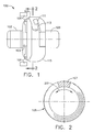
- FIG. 1 shows an elevational side view of an X-ray tube assembly according to the present disclosure.
- FIG. 2 shows a view of an anode assembly taken along line 2-2 of FIG. 1 according to the present disclosure.
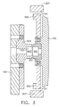
- FIG. 3 shows an elevational sectional view of an anode assembly according to of the present disclosure.
- FIG. 4 shows an oscillatory coupling according to the present disclosure.
- FIG. 5 shows a view of an anode assembly taken along line 5-5 of FIG. 4 according to the present disclosure.
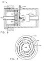
- FIG. 6 shows an elevational sectional view of an X-ray tube assembly according to the present disclosure.
- FIG. 7 shows an oscillatory coupling according to the present disclosure.
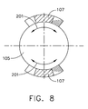
- FIG. 8 shows a view of target according to the present invention.
- FIG. 1 is a schematic view of an X-ray tube 100 having an anode assembly and a cathode assembly, through thermionic or field-emission election generation, arranged in a manner that permits formation of X-rays, during tube operation.
- the anode assembly includes a fixture 102, oscillatory coupling 103, a drive assembly 101 and target 105.
- Fixture 102 includes a substantially stationary support, which is attached to a portion of the oscillatory coupling 103.
- a first portion of the oscillatory coupling 103 attached to the fixture remains stationary while a second portion of the oscillatory coupling 103, attached to the target 105, is permitted to oscillate.
- the drive assembly 101 includes an arrangement capable of providing oscillatory motion to the target 105.
- the drive assembly 101 includes a magnetically driven motor arrangement, including fixed stator portions and movable rotor portions attached to the target 105 operably arranged to provide the oscillatory motion for the attached target 105.
- the present disclosure is not limited to the arrangement of drive assembly 101 shown and may include any arrangement capable of providing oscillatory motion to the target 105.
- oscillatory By “oscillatory”, “oscillation” and grammatical variations thereof, it is meant to include swaying motion to and fro, rotation or pivoting on an axis between two or more positions and/or motion including periodic changes in direction.
- the target 105 substrate, including the target focal surface 107 may include any material suitable for use as an anode target, such as, but not limited to copper (Cu), iron (Fe), silver (Ag), chromium (Cr), cobalt (Co), tungsten (W), molybdenum (Mo), and their alloys.
- tungsten or molybdenum having additive refractory metal components such as, tantalum, hafnium, zirconium and carbon may be utilized.
- the suitable materials may also include oxide dispersion strengthened molybdenum and molybdenum alloys, which may further include the addition of the addition of graphite to provide additional heat storage.
- suitable material may include tungsten alloys having added rhenium to improve ductility of tungsten, which may be added in small quantities (1 to 10 wt%).
- the cathode assembly 109 comprises an electron emissive portion 111 mounted to a support 113.
- the disclosure is not limited to the arrangement shown, but may be any arrangement and/or geometry that permits the formation of an electron beam at the electron emissive portion 111.
- Conductors or other current supplying mechanism may be included in the cathode assembly 109 to supply heating current to a filament and/or conductor present in the cathode assembly for maintaining the cathode at ground or negative potential relative to the target 105 of the tube 100.
- An electron beam from the electron emissive portion 111 impinges upon target 105 at a focal point on the target focal surface 107 to produce X-radiation (see e.g., FIG. 6 ).
- the focal point may be a single point or an area having any suitable geometry corresponding to the electron emissions from the electron emissive potion 111. Additionally, the focal point may have movement introduced into the beam from electrostatic, magnetic or other steering method. In addition, the focal point may be of constant size and/or geometry or may be varied in size and/or geometry, as desired for the particular application.
- "X-ray”, "X-radiation” and other grammatical variations as utilized herein mean electromagnetic radiation with a wavelength in the range of about 10 to 0.01 nanometers or other similar electromagnetic radiation. Heat is generated along the target focal surface 107 at the point of electron beam contact (i.e., the focal point).
- the target 105 is oscillated by drive assembly 101, which may include, but is not limited to, an induction or otherwise magnetically or mechanically driven drive mechanism.
- Suitable drive assemblies 101 may include, but are not limited to, voice-coil actuators or switched reluctance motors (SRM) drive.
- the drive assembly 101 may further include cams or other structures to convert rotational or other motion to oscillatory motion.
- the oscillation provides movement of the target 105, such that the focal point within the target focal surface 107 provides a substantially constant X-ray emission, wherein the target 105 moves relative to the focal point.
- the drive assembly 101 provides oscillatory motion to target 105 such that the focal point remains at a substantially fixed distance from the electron emissive portion 111 and/or the angle at which the electron beam impinges the target 105 remains substantially constant.
- the present disclosure is not limited to reflection based geometry for X-ray generation, but may include alternate configurations, such as targets 105 configured for transmission generated X-rays.
- the anode assembly and the cathode assembly 109 are housed in an envelope 115, which is under vacuum or other suitable atmosphere.
- One set-up includes a portion of the drive assembly 101 (e.g. the stator portion) exterior to the envelope. At least a portion of the envelope 115, which acts as a window for the X-rays, is glass or other material substantially transparent to X-rays.
- the configuration of the envelope 115 may be any configuration suitable for providing the X-radiation to the desired locations and may be fabricated from conventionally utilized materials.
- FIG. 2 shows a view 2-2 taken from FIG. 1 , wherein the target 105 is shown including the oscillatory motion 201. While the motion 201 is shown as a motion between equally spaced points along the target 105, the disclosure is not so limited and may include asymmetrical motion or motion with periodic changes in amplitude and/or position.
- the target focal surface 107 includes an area of target 105, which the focal point of the electron beam strikes, as the target 105 oscillates.
- the target focal surface 107 is not limited to the surface that the electron beam contacts, but includes the area surrounding the focal point.
- the target focal surface 107 preferably provides an aspect angle to which the electron beam impinges that is substantially constant and directs the X-radiation in the desired direction throughout the oscillatory motion 201 of the target 105.
- the target 105 is not limited to the geometry shown and may include segmented or otherwise non-circular geometry targets 105, for example, while not so limited, targets 105 may have a "butterfly" shape, or a multi-spot flat rectangle geometry.
- the target 105 and/or the X-ray assembly may be configured to alter the focal point and/or the target focal point surface 107 in the event that a newly exposable surface is desired, such as if the surface is damaged or otherwise unsuitable for continued use.
- FIG. 3 shows an elevational cross-section of an anode assembly according to the present disclosure.
- a target 105 is affixed to a coupling 301, which is connected to stem 303 by an oscillatory coupling 103.
- coupling 303 is attached to a first segment 401 of oscillatory coupling 103 (see e.g., FIG. 4 ).
- the stem 303 is attached to the fixture 102 or another stationary structure.
- Drive assembly 101 provides the target 105 with oscillatory motion 201.
- the drive assembly 101 includes a rotor portion 305 attached to the target and a stator portion 307 operably arranged with respect to the rotor portion 305.
- the stator portion 307 is positioned such that induced magnetic fields within the stator portion 307 drive the rotor potion 305 and provide motion (i.e., oscillatory motion) thereto.
- motion i.e., oscillatory motion
- Stem 303 is attached to a second segment 403 of oscillatory coupling 103 (see e.g., FIG. 4 ), wherein the second segment 403 is substantially fixed, while the first segment 401 oscillates relative to the second segment 403.
- the oscillatory coupling 103 provides a spring-like back and forth oscillatory motion 201 between segments 401, 403 of the oscillatory coupling 103.
- the oscillatory coupling 103 provides a pivotable or otherwise movable connection that permits the oscillatory motion 201 of the target 105 via the drive assembly 101.
- FIG. 4 shows an oscillatory coupling 103 for use in a set-up of the disclosure.
- the oscillatory coupling 103 includes a first segment 401 that rotates with respect to a second segment 403 by segment oscillation 402. During oscillation, the second segment 403 remains substantially stationary. In particular, the second segment 403 is attached to a fixture or other support that retards movement of the second segment 403, while first segment 401 is permitted to oscillate.
- FIG. 5 shows oscillatory coupling 103 taken along 5-5 of FIG. 4 .
- the oscillatory coupling 103 provides oscillatory motion 402 by a coupling mechanism 501 between the first segment 401 and the second segment 403.
- the coupling mechanism 501 may be one or more spring or force providing or otherwise flexible devices that provide connection between segments 401, 403 and reciprocating motion between segments 401, 403.
- a linear spring is utilized to provide flexing sufficient to provide oscillatory motion 201.
- the oscillatory coupling mechanism 501 may include linear springs selected to introduce motion that may be varied for desired frequency, angle and path radii.
- Coupling mechanisms 501 may have up to infinite life spans for a prescribed radial load and oscillating angle, which life spans are difficult or impossible in known rotary motion assemblies.
- the drive assembly 101 which is configured to oscillate the target 105 in a manner that results in flexing of the coupling mechanism 501, which, permits motion of the first segment 401 (i.e. oscillation 402) with respect to the second segment 403.
- the oscillation of the first segment 401 provides target 105 with oscillatory motion 201 desirable for heat management.
- the resultant oscillatory motion 201 provides a path along which the focal point travels. Since the position along the target 105 is varied, the heat generated by the impingement of the electrons on the target 105 is permitted to dissipate over a larger area. This dissipation of heat permits the use of higher power and longer durations than are available with the use of a stationary anode arrangement.
- FIG 6 shows a cross-section of an X-ray tube 100 according to another set-up of the disclosure.
- the X-ray tube 100 includes a cathode assembly 109 and an anode assembly.
- the anode assembly includes a target 105 attached to an oscillatory coupling 103.
- a portion of oscillatory coupling 103 i.e. first segment 401, see FIG. 7
- drive assembly 101 includes an arrangement of stator and rotor portions, as more fully described above with respect to FIG. 3 .
- a portion of oscillatory coupling 103 (i.e. second segment 403, see FIG. 7 ) is attached to the fixture 102, which substantially prevents motion of a portion of oscillatory coupling 103 (i.e. second segment 403, see FIG. 7 ).
- the X-ray tube 100 operates by providing an electron beam 601 by heating or otherwise providing power to the electron emissive portion 111, wherein the beam 601 impinges on target focal surface 107 at focal point 605.
- the target focal surface 107 as shown in FIG. 6 is configured to provide a substantially constant angle of impingement by the electron beam 601, throughout the oscillatory motion 201.
- the beam 601 produces X-radiation by impingement on target 105, wherein the X-radiation is directed through window 603.
- FIG. 7 shows an oscillatory coupling 103 for use in the set-up shown in FIG. 6 .
- the oscillatory coupling 103 includes a coupling mechanism 501 that connects the first segment 401 to the second segment 403 in a manner that permits relative motion (i.e., oscillatory motion 201) between the first segment 401 and the second segment 403.
- the first segment 401 may be attached to the drive assembly 101 in a manner that permits oscillatory motion 201 to the target 105.
- the drive assembly 101 rotates the target 105 where the first segment 401 flexes or otherwise moves the coupling mechanism 501 in a manner that results in oscillatory motion with respect to the second segment 403.
- the coupling mechanism 501 includes a spiral spring arrangement. Dwell time and delay time may be reduced or eliminated when the X-ray tube 100 utilizes coupling mechanism 501 shown in FIGs. 6-7 .
- the first segment 401 provides the target 105 with oscillatory motion 201, wherein the target focal surface 107 provides substantially constant X-ray production throughout the motion of the target 105.
- the present disclosure is not limited to oscillation provided through the use of a oscillatory coupling 103, but also includes direct actuation of the target 105 in a oscillatory motion 201.
- the target 105 may be affixed to a drive assembly 101, wherein the drive assembly 101 provides reciprocating rotation or oscillation of the target 105, such that the target focal surface 107 provides substantially constant production of X-rays from the electron beam 601.
- a cam or similar device may be utilized to translate rotational or other motion to oscillatory motion.
- the present disclosure is not limited to the geometry of the targets shown and may include target geometries that are asymmetrical or other non-circular arrangements. Further still, the present disclosure is not limited to a single focal point and may include multiple focal points.
- the target 105 may non-circular geometries.
- the target also includes a plurality of target focal surfaces 107 corresponding to multiple focal points.
- the target 105 oscillates in direction 201 during operation. Oscillation of the target is provided by a drive assembly 101, as described more fully above.
- the geometry of the target may vary and may include the geometry shown in FIG. 8 with a single target focal surface 107 or a plurality of target focal surfaces.
- the reduction of size and mass of the target permits the utilization of smaller drive assemblies 101 and reduced wear on components supporting the oscillating target 105.
- An example finite element analysis comparing a stationary target to a oscillating target with +/-9.5° degree oscillation at 10 Hz on a 78 mm radius arc shows an entitlement of 2.3x power increase while maintaining thermal limits of track surface temperature ⁇ 2400 °C and copper temperatures of ⁇ 300 °C.
- the power increase is gated by the optimization of the track oscillation angle, oscillation frequency and focal spot path radii.
- the power increase includes varied system size, cost and expected life span.
- the oscillatory motion introduces transient temperature fields on the surface of the anode target that will have a peak dwell time of the focal beam at the end of the oscillation path. The ends of the oscillation path determine the thermal limit of the track surface.
Abstract
Description
- This disclosure relates to an X-ray tube assembly and, more particularly, to configuration and structures for controlling heat dissipation and structural loads for an X-ray tube assembly.
- Ordinarily an X-ray beam-generating device referred to as an X-ray tube comprises dual electrodes of an electrical circuit in an evacuated chamber or tube. One of the electrodes is an electron emitter cathode which is positioned in the tube in spaced relationship to a target anode. Energization of the electrical circuit generates a stream or beam of electrons directed towards the target anode. This acceleration is generated from a high voltage differential between the anode and cathode that may range from 60-450 kV, which is a function of the imaging application. The electron stream is appropriately focused as a thin beam of very high velocity electrons striking the target anode surface. The anode surface ordinarily comprises a predetermined material, for example, a refractory metal so that the kinetic energy of the striking electrons against the target material is converted to electromagnetic waves of very high frequency, i.e. X-rays, which proceed from the target to be collimated and focused for penetration into an object usually for internal examination purposes, for example, industrial inspection procedures, healthcare imaging and treatment, or security imaging applications, food processing industries. Imaging applications include, but are not limited to, Radiography, CT, X-ray Diffraction with Cone and Fan beam x-ray fields.
- Well-known primary refractory and non-refractory metals for the anode target surface area exposed to the impinging electron beam include copper (Cu), Fe, Ag, Cr, Co, tungsten (W), molybdenum (Mo), and their alloys for X-ray generation. In addition, the high velocity beam of electrons impinging the target surface generates extremely high and localized temperatures in the target structure accompanied by high internal stresses leading to deterioration and breakdown of the target structure. As a consequence, it has become a practice to utilize a rotating anode target generally comprising a shaft supported disk-like structure, one side or face of which is exposed to the electron beam from the thermionic emitter cathode. By means of target rotation, the impinged region of the target is continuously changing to avoid localized heat concentration and stresses and to better distribute the heating effects throughout the structure. Heating remains a major problem in X-ray anode target structures. In a high speed rotating target, heating must be kept within certain proscribed limits to control potentially destructive thermal stresses particularly in composite target structures, as well as to protect low friction, solid lubricated, high precision bearings that support the target.
-
US-A-1 997 676 discloses a target electrode supported to have a swinging movement with respect to a cathode element. The target electrode is suspended by a flexible resilient strip of steel, copper or the like secured to a suitable terminal block sealed in a head of a tube structure. The pendulum movement is initiated by an electromagnet.DE 296 22 655 discloses an anode/cathode arrangement in which the anode is arranged to have a reciprocating motion relative to the cathode.JP 2001 351551A - Only about 1.0% of the energy of the impinging electron beam is converted to X-rays with the remainder appearing as heat, which must be rapidly dissipated from the target essentially by means of heat radiation. Accordingly, significant technological efforts are expended towards improving heat dissipation from X-ray anode target surfaces. For most rotating anode targets heat management must take place principally through radiation and a material with a high heat storage capacity. Stationary anode target body configurations or some complex rotating anode target configurations may be designed to have heat transfer primarily take place using conduction or convection from the target to the x-ray tube. Life of rotating x-ray targets are often gated by the complexities of rotation in a vacuum. Traditional x-ray target bearings are solid lubricated, which have relatively low life. Stationary targets do not have this life-limiting component, at the cost of lower performance.
- Other rotation components, solid lubricated bearings, ferro-fluid seals, spiral-grooved liquid metal bearings, etc, all introduce manufacturing complexity and system cost.
- What is needed is a high flux X-ray tube configuration that provides improved heat dissipation and includes components capable of maintaining an extended life, with a limited introduction of cost and manufacturing complexity.
- The present invention provides an X-ray tube assembly as defined in claim 1 and method for providing heat management to an X-ray assembly as defined in claim 10.
- One set up according to the present disclosure includes an X-ray tube anode assembly having a movable X-ray target having a target surface. The anode assembly includes a drive member arranged and disposed to provide oscillatory motion to the target assembly and a target surface that is configured to remain at a substantially fixed distance from a cathode assembly during oscillatory motion.
- Another set up according to the present disclosure includes an X-ray tube assembly including an envelope having at least a portion thereof substantially transparent to X-ray. The assembly also includes a cathode assembly, operatively positioned in the envelope with an anode assembly having a movable X-ray target having a target surface. The anode assembly includes a drive member arranged and disposed to provide oscillatory motion to the target assembly and a target surface that is configured to remain at a substantially fixed distance from a cathode assembly during oscillatory motion. This anode system may be tuned to allow the pivot to be driven at natural frequency, lowering the required drive power to obtain the desired oscillatory frequency.
- Still another set up according to the present disclosure includes a method for providing heat management to an X-ray assembly. The method includes providing an X-ray tube having an envelope having at least a portion thereof substantially transparent to X-ray. The assembly also includes a cathode assembly, operatively positioned in the envelope with an anode assembly having a movable X-ray target having a target surface. The anode assembly includes a drive member arranged and disposed to provide oscillatory motion to the target assembly and a target surface that is configured to remain at a substantially fixed distance from a cathode assembly during oscillation. The method further includes oscillating the anode assembly, wherein the target surface is configured to remain at a substantially fixed distance from the cathode assembly during the oscillating.
- The position of the focal point along the surface of the target is varied, providing improved heat management, wherein the heat may be dissipated more easily. In addition, the increased dissipation permits the use of higher power and longer durations than are available with the use of a stationary anode arrangement. In addition, the anode has increased life over anodes that have a fixed focal point on the anode. The oscillatory motion provides longer life than solid lubricated bearings used in known rotating anode sources.
- Additionally, the assembly will have reduced manufacturing complexity, and cost, in comparison to conventional rotational bearing arrangements.
- The assembly of the present invention provides multiple spots to be placed on a single target, in that each region will be thermally isolated from the neighboring spot, while maintaining the benefit of higher power through oscillatory motion from a single drive mechanism.
- The assembly of the present invention also provides for the introduction of oscillatory motion into an array of focal spots on a multi-spot anode source.
- Set-ups according to the present disclosure also allow the distribution of heat over a larger area of the anode target, through the oscillating motion, which reduces the peak temperature and maintains the temperature below the evaporation limit for the metal in the envelope, and reduces the temperature gradient between surface and substrate
- Other features and advantages of the present disclosure will be apparent from the following more detailed description of the preferred embodiment, taken in conjunction with the accompanying drawings which illustrate, by way of example, the principles of the disclosure.
-
FIG. 1 shows an elevational side view of an X-ray tube assembly according to the present disclosure. -
FIG. 2 shows a view of an anode assembly taken along line 2-2 ofFIG. 1 according to the present disclosure. -
FIG. 3 shows an elevational sectional view of an anode assembly according to of the present disclosure. -
FIG. 4 shows an oscillatory coupling according to the present disclosure. -
FIG. 5 shows a view of an anode assembly taken along line 5-5 ofFIG. 4 according to the present disclosure. -
FIG. 6 shows an elevational sectional view of an X-ray tube assembly according to the present disclosure. -
FIG. 7 shows an oscillatory coupling according to the present disclosure. -
FIG. 8 shows a view of target according to the present invention. - Wherever possible, the same reference numbers will be used throughout the drawings to refer to the same or like parts.
-
FIG. 1 is a schematic view of anX-ray tube 100 having an anode assembly and a cathode assembly, through thermionic or field-emission election generation, arranged in a manner that permits formation of X-rays, during tube operation. The anode assembly includes afixture 102,oscillatory coupling 103, adrive assembly 101 andtarget 105.Fixture 102 includes a substantially stationary support, which is attached to a portion of theoscillatory coupling 103. A first portion of theoscillatory coupling 103 attached to the fixture remains stationary while a second portion of theoscillatory coupling 103, attached to thetarget 105, is permitted to oscillate. Thedrive assembly 101 includes an arrangement capable of providing oscillatory motion to thetarget 105. In the arrangement shown, thedrive assembly 101 includes a magnetically driven motor arrangement, including fixed stator portions and movable rotor portions attached to thetarget 105 operably arranged to provide the oscillatory motion for the attachedtarget 105. The present disclosure is not limited to the arrangement ofdrive assembly 101 shown and may include any arrangement capable of providing oscillatory motion to thetarget 105. By "oscillatory", "oscillation" and grammatical variations thereof, it is meant to include swaying motion to and fro, rotation or pivoting on an axis between two or more positions and/or motion including periodic changes in direction. Thetarget 105 substrate, including the targetfocal surface 107 may include any material suitable for use as an anode target, such as, but not limited to copper (Cu), iron (Fe), silver (Ag), chromium (Cr), cobalt (Co), tungsten (W), molybdenum (Mo), and their alloys. For example, tungsten or molybdenum having additive refractory metal components, such as, tantalum, hafnium, zirconium and carbon may be utilized. The suitable materials may also include oxide dispersion strengthened molybdenum and molybdenum alloys, which may further include the addition of the addition of graphite to provide additional heat storage. Further still, suitable material may include tungsten alloys having added rhenium to improve ductility of tungsten, which may be added in small quantities (1 to 10 wt%). - The
cathode assembly 109 comprises an electronemissive portion 111 mounted to asupport 113. The disclosure is not limited to the arrangement shown, but may be any arrangement and/or geometry that permits the formation of an electron beam at the electronemissive portion 111. Conductors or other current supplying mechanism may be included in thecathode assembly 109 to supply heating current to a filament and/or conductor present in the cathode assembly for maintaining the cathode at ground or negative potential relative to thetarget 105 of thetube 100. An electron beam from the electronemissive portion 111 impinges upontarget 105 at a focal point on the targetfocal surface 107 to produce X-radiation (see e.g.,FIG. 6 ). The focal point may be a single point or an area having any suitable geometry corresponding to the electron emissions from the electronemissive potion 111. Additionally, the focal point may have movement introduced into the beam from electrostatic, magnetic or other steering method. In addition, the focal point may be of constant size and/or geometry or may be varied in size and/or geometry, as desired for the particular application. "X-ray", "X-radiation" and other grammatical variations as utilized herein mean electromagnetic radiation with a wavelength in the range of about 10 to 0.01 nanometers or other similar electromagnetic radiation. Heat is generated along the targetfocal surface 107 at the point of electron beam contact (i.e., the focal point). Thetarget 105 is oscillated bydrive assembly 101, which may include, but is not limited to, an induction or otherwise magnetically or mechanically driven drive mechanism.Suitable drive assemblies 101 may include, but are not limited to, voice-coil actuators or switched reluctance motors (SRM) drive. Thedrive assembly 101 may further include cams or other structures to convert rotational or other motion to oscillatory motion. - The oscillation provides movement of the
target 105, such that the focal point within the targetfocal surface 107 provides a substantially constant X-ray emission, wherein thetarget 105 moves relative to the focal point. Specifically, thedrive assembly 101 provides oscillatory motion to target 105 such that the focal point remains at a substantially fixed distance from the electronemissive portion 111 and/or the angle at which the electron beam impinges thetarget 105 remains substantially constant. The present disclosure is not limited to reflection based geometry for X-ray generation, but may include alternate configurations, such astargets 105 configured for transmission generated X-rays. The anode assembly and thecathode assembly 109 are housed in anenvelope 115, which is under vacuum or other suitable atmosphere. One set-up includes a portion of the drive assembly 101 (e.g. the stator portion) exterior to the envelope. At least a portion of theenvelope 115, which acts as a window for the X-rays, is glass or other material substantially transparent to X-rays. The configuration of theenvelope 115 may be any configuration suitable for providing the X-radiation to the desired locations and may be fabricated from conventionally utilized materials. -
FIG. 2 shows a view 2-2 taken fromFIG. 1 , wherein thetarget 105 is shown including theoscillatory motion 201. While themotion 201 is shown as a motion between equally spaced points along thetarget 105, the disclosure is not so limited and may include asymmetrical motion or motion with periodic changes in amplitude and/or position. The targetfocal surface 107 includes an area oftarget 105, which the focal point of the electron beam strikes, as thetarget 105 oscillates. The targetfocal surface 107 is not limited to the surface that the electron beam contacts, but includes the area surrounding the focal point. The targetfocal surface 107 preferably provides an aspect angle to which the electron beam impinges that is substantially constant and directs the X-radiation in the desired direction throughout theoscillatory motion 201 of thetarget 105. Thetarget 105 is not limited to the geometry shown and may include segmented or otherwisenon-circular geometry targets 105, for example, while not so limited, targets 105 may have a "butterfly" shape, or a multi-spot flat rectangle geometry. In addition, thetarget 105 and/or the X-ray assembly may be configured to alter the focal point and/or the targetfocal point surface 107 in the event that a newly exposable surface is desired, such as if the surface is damaged or otherwise unsuitable for continued use. -
FIG. 3 shows an elevational cross-section of an anode assembly according to the present disclosure. In this set-up, atarget 105 is affixed to acoupling 301, which is connected to stem 303 by anoscillatory coupling 103. In particular, coupling 303 is attached to afirst segment 401 of oscillatory coupling 103 (see e.g.,FIG. 4 ). Thestem 303 is attached to thefixture 102 or another stationary structure.Drive assembly 101 provides thetarget 105 withoscillatory motion 201. As shown, thedrive assembly 101 includes arotor portion 305 attached to the target and astator portion 307 operably arranged with respect to therotor portion 305. Specifically, thestator portion 307 is positioned such that induced magnetic fields within thestator portion 307 drive therotor potion 305 and provide motion (i.e., oscillatory motion) thereto. One skilled in the art would also understand that this could oscillatory motion may also be provided utilizing bearing configurations.Stem 303 is attached to asecond segment 403 of oscillatory coupling 103 (see e.g.,FIG. 4 ), wherein thesecond segment 403 is substantially fixed, while thefirst segment 401 oscillates relative to thesecond segment 403. Theoscillatory coupling 103 provides a spring-like back and forthoscillatory motion 201 betweensegments oscillatory coupling 103. Theoscillatory coupling 103 provides a pivotable or otherwise movable connection that permits theoscillatory motion 201 of thetarget 105 via thedrive assembly 101. -
FIG. 4 shows anoscillatory coupling 103 for use in a set-up of the disclosure. Theoscillatory coupling 103 includes afirst segment 401 that rotates with respect to asecond segment 403 bysegment oscillation 402. During oscillation, thesecond segment 403 remains substantially stationary. In particular, thesecond segment 403 is attached to a fixture or other support that retards movement of thesecond segment 403, whilefirst segment 401 is permitted to oscillate.FIG. 5 showsoscillatory coupling 103 taken along 5-5 ofFIG. 4 . Theoscillatory coupling 103 providesoscillatory motion 402 by acoupling mechanism 501 between thefirst segment 401 and thesecond segment 403. Thecoupling mechanism 501 may be one or more spring or force providing or otherwise flexible devices that provide connection betweensegments segments FIGs. 3-5 , a linear spring is utilized to provide flexing sufficient to provideoscillatory motion 201. Theoscillatory coupling mechanism 501 may include linear springs selected to introduce motion that may be varied for desired frequency, angle and path radii. - Coupling
mechanisms 501, for example, utilizing linear springs to provide oscillation, may have up to infinite life spans for a prescribed radial load and oscillating angle, which life spans are difficult or impossible in known rotary motion assemblies. During operation ofX-ray tube 100, thedrive assembly 101, which is configured to oscillate thetarget 105 in a manner that results in flexing of thecoupling mechanism 501, which, permits motion of the first segment 401 (i.e. oscillation 402) with respect to thesecond segment 403. The oscillation of thefirst segment 401 providestarget 105 withoscillatory motion 201 desirable for heat management. - The resultant
oscillatory motion 201 provides a path along which the focal point travels. Since the position along thetarget 105 is varied, the heat generated by the impingement of the electrons on thetarget 105 is permitted to dissipate over a larger area. This dissipation of heat permits the use of higher power and longer durations than are available with the use of a stationary anode arrangement. -
FIG 6 shows a cross-section of anX-ray tube 100 according to another set-up of the disclosure. As in the set-up shown inFIG. 1 , theX-ray tube 100 includes acathode assembly 109 and an anode assembly. The anode assembly includes atarget 105 attached to anoscillatory coupling 103. A portion of oscillatory coupling 103 (i.e.first segment 401, seeFIG. 7 ) is attached to adrive assembly 101, which is configured to provide oscillatory motion to thetarget 105 by magnetic or other means. InFIG. 6 ,drive assembly 101 includes an arrangement of stator and rotor portions, as more fully described above with respect toFIG. 3 . In addition, a portion of oscillatory coupling 103 (i.e.second segment 403, seeFIG. 7 ) is attached to thefixture 102, which substantially prevents motion of a portion of oscillatory coupling 103 (i.e.second segment 403, seeFIG. 7 ). TheX-ray tube 100 operates by providing anelectron beam 601 by heating or otherwise providing power to the electronemissive portion 111, wherein thebeam 601 impinges on targetfocal surface 107 atfocal point 605. The targetfocal surface 107, as shown inFIG. 6 is configured to provide a substantially constant angle of impingement by theelectron beam 601, throughout theoscillatory motion 201. Thebeam 601 produces X-radiation by impingement ontarget 105, wherein the X-radiation is directed throughwindow 603. -
FIG. 7 shows anoscillatory coupling 103 for use in the set-up shown inFIG. 6 . Theoscillatory coupling 103 includes acoupling mechanism 501 that connects thefirst segment 401 to thesecond segment 403 in a manner that permits relative motion (i.e., oscillatory motion 201) between thefirst segment 401 and thesecond segment 403. As in thecoupling 103 shown and described inFIGs. 4 and 5 , thefirst segment 401 may be attached to thedrive assembly 101 in a manner that permitsoscillatory motion 201 to thetarget 105. Thedrive assembly 101 rotates thetarget 105 where thefirst segment 401 flexes or otherwise moves thecoupling mechanism 501 in a manner that results in oscillatory motion with respect to thesecond segment 403. In the set-up shown inFIGs. 6-7 , thecoupling mechanism 501 includes a spiral spring arrangement. Dwell time and delay time may be reduced or eliminated when theX-ray tube 100 utilizescoupling mechanism 501 shown inFIGs. 6-7 . Thefirst segment 401 provides thetarget 105 withoscillatory motion 201, wherein the targetfocal surface 107 provides substantially constant X-ray production throughout the motion of thetarget 105. - The present disclosure is not limited to oscillation provided through the use of a
oscillatory coupling 103, but also includes direct actuation of thetarget 105 in aoscillatory motion 201. For example, thetarget 105 may be affixed to adrive assembly 101, wherein thedrive assembly 101 provides reciprocating rotation or oscillation of thetarget 105, such that the targetfocal surface 107 provides substantially constant production of X-rays from theelectron beam 601. Other configurations, such as a linear orelongated target 105 having an oscillated targetfocal surface 107 actuated by a linear actuator or other linear motion device. Further a cam or similar device may be utilized to translate rotational or other motion to oscillatory motion. In addition, the present disclosure is not limited to the geometry of the targets shown and may include target geometries that are asymmetrical or other non-circular arrangements. Further still, the present disclosure is not limited to a single focal point and may include multiple focal points. - As shown in
FIG. 8 , thetarget 105 may non-circular geometries. The target also includes a plurality of targetfocal surfaces 107 corresponding to multiple focal points. Thetarget 105 oscillates indirection 201 during operation. Oscillation of the target is provided by adrive assembly 101, as described more fully above. The geometry of the target may vary and may include the geometry shown inFIG. 8 with a single targetfocal surface 107 or a plurality of target focal surfaces. In addition, the reduction of size and mass of the target permits the utilization ofsmaller drive assemblies 101 and reduced wear on components supporting theoscillating target 105. - An example finite element analysis comparing a stationary target to a oscillating target with +/-9.5° degree oscillation at 10 Hz on a 78 mm radius arc shows an entitlement of 2.3x power increase while maintaining thermal limits of track surface temperature < 2400 °C and copper temperatures of < 300 °C. One skilled in the art would note that the power increase is gated by the optimization of the track oscillation angle, oscillation frequency and focal spot path radii. In addition, the power increase includes varied system size, cost and expected life span. The oscillatory motion introduces transient temperature fields on the surface of the anode target that will have a peak dwell time of the focal beam at the end of the oscillation path. The ends of the oscillation path determine the thermal limit of the track surface.
- While the disclosure has been described with reference to preferred set-ups it will be understood by those skilled in the art that various changes may be made without departing from the scope of the disclosure. In addition, many modifications may be made to adapt a particular situation or material to the teachings of the disclosure without departing from the essential scope thereof. Therefore, it is intended that the disclosure not be limited to the particular set-ups disclosed as the best mode contemplated for carrying out this disclosure, but that the disclosure will include all embodiments falling within the scope of the appended claims.
Claims (11)
- An X-ray tube assembly comprising:an envelope having at least a portion thereof substantially transparent to X-ray;a cathode assembly (109), operatively positioned in the envelope with an anode assembly comprising:a movable X-ray target (105) having a target surface (107);a drive member (101) arranged and disposed to provide oscillatory motion to the target assembly; the target (105) arranged to oscillate rotationally during operation;wherein the target surface (107) is configured to remain at a substantially fixed distance from the cathode assembly (109) during oscillatory motion; andcharacterized in that the cathode assembly (109) and target surface (107) are configured to provide multiple focal points and in that the target surface (107) includes a plurality of target focal surfaces (107) corresponding to these multiple focal points.
- The anode assembly of claim 1, wherein the target surface is configured to provide a reflection X-ray generation.
- The anode assembly of claim 1, wherein the target surface is configured to provide a transmission X-ray generation.
- The anode assembly of claim 1, further comprising an oscillatory coupling between the drive member and the target.
- The anode assembly of claim 4, wherein the oscillatory coupling includes a substantially linear coupling.
- The anode assembly of claim 1, wherein the target has two or more segments each comprising the target surface.
- The anode assembly of claim 1, wherein the assembly is configured to be radiatively, conductively or convectively cooled.
- The anode assembly of claim 1, wherein the drive member includes an induction motor to provide oscillation to the target.
- The X-ray tube anode assembly of claim 1, further comprising:an oscillatory coupling (103) including a first segment (401) and a second segment (403), the first segment (401) being rotatable with respect to the second segment (403) by segment oscillation; andwherein the drive member (101) includes a magnetically driven motor arrangement, including fixed stator portions and movable rotor portions attached to the target (105).
- A method for providing heat management to an X-ray assembly, the method comprising:providing an X-ray tube assembly having:an envelope having at least a portion thereof substantially transparent to X-ray;a cathode assembly, operatively positioned in the envelope;an anode assembly comprising:a movable X-ray target having a target surface; anda drive member arranged and disposed to provide oscillatory motion to the target assembly; androtationally oscillating the anode assembly, during operation, wherein the target surface is configured to remain at a substantially fixed distance from the cathode assembly during the oscillating;characterized in that the cathode assembly (109) and target surface (107) are configured to provide multiple focal points and in that the target surface (107) includes a plurality of target focal surfaces (107) corresponding to these multiple focal points.
- The method of claim 10, further providing an oscillatory coupling between the drive member and the target.
Applications Claiming Priority (2)
| Application Number | Priority Date | Filing Date | Title |
|---|---|---|---|
| US11/856,328 US7751530B2 (en) | 2007-09-17 | 2007-09-17 | High flux X-ray target and assembly |
| PCT/US2008/071102 WO2009038871A1 (en) | 2007-09-17 | 2008-07-25 | High flux x-ray target and assembly |
Publications (2)
| Publication Number | Publication Date |
|---|---|
| EP2201592A1 EP2201592A1 (en) | 2010-06-30 |
| EP2201592B1 true EP2201592B1 (en) | 2012-03-07 |
Family
ID=39870510
Family Applications (1)
| Application Number | Title | Priority Date | Filing Date |
|---|---|---|---|
| EP08782363A Not-in-force EP2201592B1 (en) | 2007-09-17 | 2008-07-25 | High flux x-ray target and assembly |
Country Status (4)
| Country | Link |
|---|---|
| US (1) | US7751530B2 (en) |
| EP (1) | EP2201592B1 (en) |
| AT (1) | ATE548747T1 (en) |
| WO (1) | WO2009038871A1 (en) |
Families Citing this family (10)
| Publication number | Priority date | Publication date | Assignee | Title |
|---|---|---|---|---|
| US20100284518A1 (en) * | 2007-12-31 | 2010-11-11 | Anupam Singh Ahlawat | Pivoting high flux x-ray target and assembly |
| US7852988B2 (en) * | 2008-07-31 | 2010-12-14 | General Electric Company | High flux X-ray target and assembly |
| US20100128848A1 (en) * | 2008-11-21 | 2010-05-27 | General Electric Company | X-ray tube having liquid lubricated bearings and liquid cooled target |
| DE102011079484A1 (en) * | 2011-07-20 | 2013-01-24 | Siemens Aktiengesellschaft | Method and system for determining emissivity |
| GB201118556D0 (en) | 2011-10-27 | 2011-12-07 | Isis Innovation | X-ray generation |
| US9237872B2 (en) | 2013-01-18 | 2016-01-19 | General Electric Company | X-ray source with moving anode or cathode |
| GB201420936D0 (en) | 2014-11-25 | 2015-01-07 | Isis Innovation | Radio frequency cavities |
| CN109362169A (en) * | 2018-12-24 | 2019-02-19 | 中广核达胜加速器技术有限公司 | A kind of bearing conversion equipment of electron accelerator X-ray conversion target |
| TW202230419A (en) * | 2020-09-30 | 2022-08-01 | 美商Ncx公司 | X-ray source and method for forming same |
| CN113782406A (en) * | 2021-09-30 | 2021-12-10 | 中广核达胜加速器技术有限公司 | Swing type high-power X-ray conversion target device |
Family Cites Families (15)
| Publication number | Priority date | Publication date | Assignee | Title |
|---|---|---|---|---|
| US1997676A (en) | 1933-02-11 | 1935-04-16 | Kenneth G Catlin | X-ray tube |
| US2926270A (en) * | 1957-12-30 | 1960-02-23 | Gen Electric | Rotating anode x-ray tube |
| US3398307A (en) * | 1962-05-28 | 1968-08-20 | Varian Associates | Electron beam X-ray generator with rotatable target movable along axis of rotation |
| US3836805A (en) * | 1973-05-21 | 1974-09-17 | Philips Corp | Rotating anode x-ray tube |
| GB1579341A (en) * | 1976-04-28 | 1980-11-19 | Emi Ltd | X-ray generating tubes |
| US4162420A (en) * | 1978-06-05 | 1979-07-24 | Grady John K | X-ray tube having rotatable and reciprocable anode |
| US4399551A (en) * | 1980-09-29 | 1983-08-16 | Grady John K | X-Ray tube having rotatable transversely oscillatory anode |
| DE29622655U1 (en) | 1996-01-30 | 1997-03-20 | Siemens Ag | X-ray tube |
| JP2001351551A (en) | 2000-06-06 | 2001-12-21 | Kazuo Taniguchi | X-ray tube |
| JP4174626B2 (en) * | 2002-07-19 | 2008-11-05 | 株式会社島津製作所 | X-ray generator |
| US7042975B2 (en) * | 2002-10-25 | 2006-05-09 | Koninklijke Philips Electronics N.V. | Four-dimensional helical tomographic scanner |
| JP2007531204A (en) * | 2003-07-18 | 2007-11-01 | コーニンクレッカ フィリップス エレクトロニクス エヌ ヴィ | Cylindrical X-ray tube for CT imaging |
| JP4238245B2 (en) * | 2005-09-14 | 2009-03-18 | 知平 坂部 | X-ray generation method and X-ray generation apparatus |
| JP2009536432A (en) * | 2006-05-05 | 2009-10-08 | コーニンクレッカ フィリップス エレクトロニクス エヌ ヴィ | X-ray tube with oscillating anode |
| US7852988B2 (en) * | 2008-07-31 | 2010-12-14 | General Electric Company | High flux X-ray target and assembly |
-
2007
- 2007-09-17 US US11/856,328 patent/US7751530B2/en not_active Expired - Fee Related
-
2008
- 2008-07-25 WO PCT/US2008/071102 patent/WO2009038871A1/en active Application Filing
- 2008-07-25 AT AT08782363T patent/ATE548747T1/en active
- 2008-07-25 EP EP08782363A patent/EP2201592B1/en not_active Not-in-force
Also Published As
| Publication number | Publication date |
|---|---|
| EP2201592A1 (en) | 2010-06-30 |
| US20090074145A1 (en) | 2009-03-19 |
| ATE548747T1 (en) | 2012-03-15 |
| WO2009038871A1 (en) | 2009-03-26 |
| US7751530B2 (en) | 2010-07-06 |
Similar Documents
| Publication | Publication Date | Title |
|---|---|---|
| EP2201592B1 (en) | High flux x-ray target and assembly | |
| US7852988B2 (en) | High flux X-ray target and assembly | |
| EP0715333B1 (en) | X-ray tube assemblies | |
| US7515687B2 (en) | Compact source with very bright X-ray beam | |
| EP0496945B1 (en) | Rotary-anode type x-ray tube | |
| KR102201864B1 (en) | Electromagnetic induction and receiving element | |
| US20100284518A1 (en) | Pivoting high flux x-ray target and assembly | |
| KR970002680B1 (en) | X-ray tube of the rotary anode type | |
| US6873683B2 (en) | Axial flux motor driven anode target for X-ray tube | |
| EP1719150B1 (en) | X-ray source | |
| US8379798B2 (en) | Moving high flux X-ray target and assembly | |
| EP2225769A1 (en) | Precession anode x-ray tube | |
| US6144720A (en) | Iron oxide coating for x-ray tube rotors | |
| US3851204A (en) | Rotatable anode for x-ray tubes | |
| JP2004353867A (en) | Electrically conducting ceramic bearing | |
| CN113764244A (en) | X-ray radiator and X-ray device | |
| JPH1040842A (en) | X-ray tube | |
| WO2021129943A1 (en) | X-ray target assembly, x-ray anode assembly and x-ray tube apparatus | |
| WO2022219537A1 (en) | X-ray source with anode exchange arrangement, and associated method | |
| EP1459350A1 (en) | Device for generating x-rays having an integrated anode and bearing member | |
| GB2038083A (en) | X-ray tube target | |
| Arkadiev et al. | 2.2 X-Ray Tubes | |
| JP2011526058A (en) | Mount for rotating target | |
| JP2007115545A (en) | Rotating anode x-ray tube |
Legal Events
| Date | Code | Title | Description |
|---|---|---|---|
| PUAI | Public reference made under article 153(3) epc to a published international application that has entered the european phase |
Free format text: ORIGINAL CODE: 0009012 |
|
| 17P | Request for examination filed |
Effective date: 20100419 |
|
| AK | Designated contracting states |
Kind code of ref document: A1 Designated state(s): AT BE BG CH CY CZ DE DK EE ES FI FR GB GR HR HU IE IS IT LI LT LU LV MC MT NL NO PL PT RO SE SI SK TR |
|
| AX | Request for extension of the european patent |
Extension state: AL BA MK RS |
|
| 17Q | First examination report despatched |
Effective date: 20100903 |
|
| DAX | Request for extension of the european patent (deleted) | ||
| GRAP | Despatch of communication of intention to grant a patent |
Free format text: ORIGINAL CODE: EPIDOSNIGR1 |
|
| GRAS | Grant fee paid |
Free format text: ORIGINAL CODE: EPIDOSNIGR3 |
|
| GRAA | (expected) grant |
Free format text: ORIGINAL CODE: 0009210 |
|
| AK | Designated contracting states |
Kind code of ref document: B1 Designated state(s): AT BE BG CH CY CZ DE DK EE ES FI FR GB GR HR HU IE IS IT LI LT LU LV MC MT NL NO PL PT RO SE SI SK TR |
|
| REG | Reference to a national code |
Ref country code: GB Ref legal event code: FG4D |
|
| REG | Reference to a national code |
Ref country code: AT Ref legal event code: REF Ref document number: 548747 Country of ref document: AT Kind code of ref document: T Effective date: 20120315 Ref country code: CH Ref legal event code: EP |
|
| REG | Reference to a national code |
Ref country code: IE Ref legal event code: FG4D |
|
| REG | Reference to a national code |
Ref country code: DE Ref legal event code: R096 Ref document number: 602008013990 Country of ref document: DE Effective date: 20120503 |
|
| REG | Reference to a national code |
Ref country code: NL Ref legal event code: VDEP Effective date: 20120307 |
|
| PG25 | Lapsed in a contracting state [announced via postgrant information from national office to epo] |
Ref country code: LT Free format text: LAPSE BECAUSE OF FAILURE TO SUBMIT A TRANSLATION OF THE DESCRIPTION OR TO PAY THE FEE WITHIN THE PRESCRIBED TIME-LIMIT Effective date: 20120307 Ref country code: NO Free format text: LAPSE BECAUSE OF FAILURE TO SUBMIT A TRANSLATION OF THE DESCRIPTION OR TO PAY THE FEE WITHIN THE PRESCRIBED TIME-LIMIT Effective date: 20120607 Ref country code: NL Free format text: LAPSE BECAUSE OF FAILURE TO SUBMIT A TRANSLATION OF THE DESCRIPTION OR TO PAY THE FEE WITHIN THE PRESCRIBED TIME-LIMIT Effective date: 20120307 Ref country code: HR Free format text: LAPSE BECAUSE OF FAILURE TO SUBMIT A TRANSLATION OF THE DESCRIPTION OR TO PAY THE FEE WITHIN THE PRESCRIBED TIME-LIMIT Effective date: 20120307 |
|
| LTIE | Lt: invalidation of european patent or patent extension |
Effective date: 20120307 |
|
| PG25 | Lapsed in a contracting state [announced via postgrant information from national office to epo] |
Ref country code: LV Free format text: LAPSE BECAUSE OF FAILURE TO SUBMIT A TRANSLATION OF THE DESCRIPTION OR TO PAY THE FEE WITHIN THE PRESCRIBED TIME-LIMIT Effective date: 20120307 Ref country code: GR Free format text: LAPSE BECAUSE OF FAILURE TO SUBMIT A TRANSLATION OF THE DESCRIPTION OR TO PAY THE FEE WITHIN THE PRESCRIBED TIME-LIMIT Effective date: 20120608 Ref country code: FI Free format text: LAPSE BECAUSE OF FAILURE TO SUBMIT A TRANSLATION OF THE DESCRIPTION OR TO PAY THE FEE WITHIN THE PRESCRIBED TIME-LIMIT Effective date: 20120307 |
|
| REG | Reference to a national code |
Ref country code: AT Ref legal event code: MK05 Ref document number: 548747 Country of ref document: AT Kind code of ref document: T Effective date: 20120307 |
|
| PG25 | Lapsed in a contracting state [announced via postgrant information from national office to epo] |
Ref country code: CY Free format text: LAPSE BECAUSE OF FAILURE TO SUBMIT A TRANSLATION OF THE DESCRIPTION OR TO PAY THE FEE WITHIN THE PRESCRIBED TIME-LIMIT Effective date: 20120307 |
|
| PG25 | Lapsed in a contracting state [announced via postgrant information from national office to epo] |
Ref country code: RO Free format text: LAPSE BECAUSE OF FAILURE TO SUBMIT A TRANSLATION OF THE DESCRIPTION OR TO PAY THE FEE WITHIN THE PRESCRIBED TIME-LIMIT Effective date: 20120307 Ref country code: IS Free format text: LAPSE BECAUSE OF FAILURE TO SUBMIT A TRANSLATION OF THE DESCRIPTION OR TO PAY THE FEE WITHIN THE PRESCRIBED TIME-LIMIT Effective date: 20120707 Ref country code: PL Free format text: LAPSE BECAUSE OF FAILURE TO SUBMIT A TRANSLATION OF THE DESCRIPTION OR TO PAY THE FEE WITHIN THE PRESCRIBED TIME-LIMIT Effective date: 20120307 Ref country code: SE Free format text: LAPSE BECAUSE OF FAILURE TO SUBMIT A TRANSLATION OF THE DESCRIPTION OR TO PAY THE FEE WITHIN THE PRESCRIBED TIME-LIMIT Effective date: 20120307 Ref country code: SI Free format text: LAPSE BECAUSE OF FAILURE TO SUBMIT A TRANSLATION OF THE DESCRIPTION OR TO PAY THE FEE WITHIN THE PRESCRIBED TIME-LIMIT Effective date: 20120307 Ref country code: EE Free format text: LAPSE BECAUSE OF FAILURE TO SUBMIT A TRANSLATION OF THE DESCRIPTION OR TO PAY THE FEE WITHIN THE PRESCRIBED TIME-LIMIT Effective date: 20120307 Ref country code: BE Free format text: LAPSE BECAUSE OF FAILURE TO SUBMIT A TRANSLATION OF THE DESCRIPTION OR TO PAY THE FEE WITHIN THE PRESCRIBED TIME-LIMIT Effective date: 20120307 Ref country code: CZ Free format text: LAPSE BECAUSE OF FAILURE TO SUBMIT A TRANSLATION OF THE DESCRIPTION OR TO PAY THE FEE WITHIN THE PRESCRIBED TIME-LIMIT Effective date: 20120307 |
|
| PG25 | Lapsed in a contracting state [announced via postgrant information from national office to epo] |
Ref country code: SK Free format text: LAPSE BECAUSE OF FAILURE TO SUBMIT A TRANSLATION OF THE DESCRIPTION OR TO PAY THE FEE WITHIN THE PRESCRIBED TIME-LIMIT Effective date: 20120307 Ref country code: PT Free format text: LAPSE BECAUSE OF FAILURE TO SUBMIT A TRANSLATION OF THE DESCRIPTION OR TO PAY THE FEE WITHIN THE PRESCRIBED TIME-LIMIT Effective date: 20120709 |
|
| PLBE | No opposition filed within time limit |
Free format text: ORIGINAL CODE: 0009261 |
|
| STAA | Information on the status of an ep patent application or granted ep patent |
Free format text: STATUS: NO OPPOSITION FILED WITHIN TIME LIMIT |
|
| PG25 | Lapsed in a contracting state [announced via postgrant information from national office to epo] |
Ref country code: DK Free format text: LAPSE BECAUSE OF FAILURE TO SUBMIT A TRANSLATION OF THE DESCRIPTION OR TO PAY THE FEE WITHIN THE PRESCRIBED TIME-LIMIT Effective date: 20120307 Ref country code: AT Free format text: LAPSE BECAUSE OF FAILURE TO SUBMIT A TRANSLATION OF THE DESCRIPTION OR TO PAY THE FEE WITHIN THE PRESCRIBED TIME-LIMIT Effective date: 20120307 |
|
| 26N | No opposition filed |
Effective date: 20121210 |
|
| PG25 | Lapsed in a contracting state [announced via postgrant information from national office to epo] |
Ref country code: MC Free format text: LAPSE BECAUSE OF NON-PAYMENT OF DUE FEES Effective date: 20120731 Ref country code: IT Free format text: LAPSE BECAUSE OF FAILURE TO SUBMIT A TRANSLATION OF THE DESCRIPTION OR TO PAY THE FEE WITHIN THE PRESCRIBED TIME-LIMIT Effective date: 20120307 |
|
| REG | Reference to a national code |
Ref country code: CH Ref legal event code: PL |
|
| REG | Reference to a national code |
Ref country code: DE Ref legal event code: R097 Ref document number: 602008013990 Country of ref document: DE Effective date: 20121210 |
|
| PG25 | Lapsed in a contracting state [announced via postgrant information from national office to epo] |
Ref country code: CH Free format text: LAPSE BECAUSE OF NON-PAYMENT OF DUE FEES Effective date: 20120731 Ref country code: LI Free format text: LAPSE BECAUSE OF NON-PAYMENT OF DUE FEES Effective date: 20120731 Ref country code: ES Free format text: LAPSE BECAUSE OF FAILURE TO SUBMIT A TRANSLATION OF THE DESCRIPTION OR TO PAY THE FEE WITHIN THE PRESCRIBED TIME-LIMIT Effective date: 20120618 |
|
| REG | Reference to a national code |
Ref country code: IE Ref legal event code: MM4A |
|
| PG25 | Lapsed in a contracting state [announced via postgrant information from national office to epo] |
Ref country code: BG Free format text: LAPSE BECAUSE OF FAILURE TO SUBMIT A TRANSLATION OF THE DESCRIPTION OR TO PAY THE FEE WITHIN THE PRESCRIBED TIME-LIMIT Effective date: 20120607 Ref country code: MT Free format text: LAPSE BECAUSE OF FAILURE TO SUBMIT A TRANSLATION OF THE DESCRIPTION OR TO PAY THE FEE WITHIN THE PRESCRIBED TIME-LIMIT Effective date: 20120307 Ref country code: IE Free format text: LAPSE BECAUSE OF NON-PAYMENT OF DUE FEES Effective date: 20120725 |
|
| PG25 | Lapsed in a contracting state [announced via postgrant information from national office to epo] |
Ref country code: TR Free format text: LAPSE BECAUSE OF FAILURE TO SUBMIT A TRANSLATION OF THE DESCRIPTION OR TO PAY THE FEE WITHIN THE PRESCRIBED TIME-LIMIT Effective date: 20120307 |
|
| PG25 | Lapsed in a contracting state [announced via postgrant information from national office to epo] |
Ref country code: LU Free format text: LAPSE BECAUSE OF NON-PAYMENT OF DUE FEES Effective date: 20120725 |
|
| PG25 | Lapsed in a contracting state [announced via postgrant information from national office to epo] |
Ref country code: HU Free format text: LAPSE BECAUSE OF FAILURE TO SUBMIT A TRANSLATION OF THE DESCRIPTION OR TO PAY THE FEE WITHIN THE PRESCRIBED TIME-LIMIT Effective date: 20080725 |
|
| REG | Reference to a national code |
Ref country code: FR Ref legal event code: PLFP Year of fee payment: 8 |
|
| PGFP | Annual fee paid to national office [announced via postgrant information from national office to epo] |
Ref country code: GB Payment date: 20150727 Year of fee payment: 8 |
|
| PGFP | Annual fee paid to national office [announced via postgrant information from national office to epo] |
Ref country code: FR Payment date: 20150717 Year of fee payment: 8 |
|
| GBPC | Gb: european patent ceased through non-payment of renewal fee |
Effective date: 20160725 |
|
| PG25 | Lapsed in a contracting state [announced via postgrant information from national office to epo] |
Ref country code: FR Free format text: LAPSE BECAUSE OF NON-PAYMENT OF DUE FEES Effective date: 20160801 |
|
| REG | Reference to a national code |
Ref country code: FR Ref legal event code: ST Effective date: 20170331 |
|
| PG25 | Lapsed in a contracting state [announced via postgrant information from national office to epo] |
Ref country code: GB Free format text: LAPSE BECAUSE OF NON-PAYMENT OF DUE FEES Effective date: 20160725 |
|
| PGFP | Annual fee paid to national office [announced via postgrant information from national office to epo] |
Ref country code: DE Payment date: 20200622 Year of fee payment: 13 |
|
| REG | Reference to a national code |
Ref country code: DE Ref legal event code: R119 Ref document number: 602008013990 Country of ref document: DE |
|
| PG25 | Lapsed in a contracting state [announced via postgrant information from national office to epo] |
Ref country code: DE Free format text: LAPSE BECAUSE OF NON-PAYMENT OF DUE FEES Effective date: 20220201 |