EP2201210B1 - Variable position gas trap - Google Patents
Variable position gas trap Download PDFInfo
- Publication number
- EP2201210B1 EP2201210B1 EP08795445.9A EP08795445A EP2201210B1 EP 2201210 B1 EP2201210 B1 EP 2201210B1 EP 08795445 A EP08795445 A EP 08795445A EP 2201210 B1 EP2201210 B1 EP 2201210B1
- Authority
- EP
- European Patent Office
- Prior art keywords
- gas trap
- carriage
- variable position
- frame
- set forth
- Prior art date
- Legal status (The legal status is an assumption and is not a legal conclusion. Google has not performed a legal analysis and makes no representation as to the accuracy of the status listed.)
- Not-in-force
Links
Images


Classifications
-
- E—FIXED CONSTRUCTIONS
- E21—EARTH OR ROCK DRILLING; MINING
- E21B—EARTH OR ROCK DRILLING; OBTAINING OIL, GAS, WATER, SOLUBLE OR MELTABLE MATERIALS OR A SLURRY OF MINERALS FROM WELLS
- E21B21/00—Methods or apparatus for flushing boreholes, e.g. by use of exhaust air from motor
- E21B21/06—Arrangements for treating drilling fluids outside the borehole
- E21B21/063—Arrangements for treating drilling fluids outside the borehole by separating components
- E21B21/067—Separating gases from drilling fluids
-
- E—FIXED CONSTRUCTIONS
- E21—EARTH OR ROCK DRILLING; MINING
- E21B—EARTH OR ROCK DRILLING; OBTAINING OIL, GAS, WATER, SOLUBLE OR MELTABLE MATERIALS OR A SLURRY OF MINERALS FROM WELLS
- E21B49/00—Testing the nature of borehole walls; Formation testing; Methods or apparatus for obtaining samples of soil or well fluids, specially adapted to earth drilling or wells
- E21B49/005—Testing the nature of borehole walls or the formation by using drilling mud or cutting data
Definitions
- the present invention is directed to a variable position gas trap apparatus and method used to separate gases entrained in drilling fluid in a tank.
- the present invention is directed to a variable position gas trap apparatus wherein a feedback control loop mechanically and automatically adjusts the height of the gas trap in response to changes in the level of the drilling fluid in the tank.
- drilling fluid or fluids while drilling subterranean wells is well-known.
- the drilling fluid or fluids may be aqueous-based, but are most often hydrocarbon or petroleum-based.
- the drilling fluids are referred to as base fluid, drilling mud or, simply, mud.
- Drilling fluid is used for a number of reasons.
- the drilling fluid is pumped downhole to the site where the drill bit is operating and is used to carry dirt, debris, rocks and chips broken off by action of the drill bit.
- the drilling fluid also assists in cooling the area where the drill bit operates.
- the drilling fluid may contain other additives, such as special lubricants, and is relatively expensive.
- the drilling fluid is typically contained in a closed looped system. Upon return to the surface from downhole, the drilling fluid is often processed with a vibrating shaker or "shale shaker" which contains a screen so that the drilling fluid passes through the screen while rocks or other items above a certain size are separated out.
- the drilling fluid is stored in an open container or tank or a series of containers and then returned back down hole in a continuous system.
- Zamfes U.S. Patent No. 6,389,878 shows one example of a gas trap.
- a canister or container is partially submerged in the drilling fluid in the mud tank and permits drilling mud to enter from the base and exit from a side.
- the gas trap includes a motor which rotates a blade or stirrer to assist in releasing gas bubbles which are then taken to a gas collection port for analysis.
- gas traps There are various types of gas traps, but most of them operate on similar basic principles.
- the gas traps are strapped or otherwise secured inside of the drilling mud tank. Changes in the operation of the drilling equipment or the drilling fluid pump can alter the level of fluid in the tank. If the drilling mud level in the tank or container changes, the operation of the gas trap may be affected. If the level of the drilling mud is too low, not enough mud will enter the gas trap, so that primarily atmospheric air will enter the gas trap. If the level of drilling fluid is too high, it may affect the efficiency of separation of the gas bubbles from the drilling fluid or, in an extreme case, mud may enter the analysis equipment. While it is possible to manually move the gas trap in response to changes in the level, there is an ongoing effort to minimize required personnel at a drilling location.
- Prior devices include Ratcliff ( U.S. Patent No. 4,358,298 ) which discloses a rack gear 66 that operates with a pinion gear 86 so that manual rotation of a crank 90 permits vertical adjustment of the gas trap. No automatic adjustment is provided.
- Naess U.S. Patent No. 4,447,247 discloses a submerged mechanism to collect gas flowing into a body of water with an upper member 2 and ballast tanks 13 for adjusting the displacement of the upper member in an underwater blow-out.
- variable position gas trap apparatus having a feedback control loop for height adjustment.
- variable position gas trap that is compact in design and reliable in operation.
- the present invention provides a variable position gas trap apparatus utilized to separate gases which are entrained in drilling fluid in a container or a tank.
- the present invention provides for automatic and especially mechanical height adjustment in response to surface level change of the drilling fluid.
- the apparatus operates with and includes a gas trap container having an open base and a motor wherein the motor rotates a shaft. Extending from the shaft is a stirrer which extends into the gas trap container to stir the drilling fluid and assists in releasing gases contained within the drilling fluid.
- the gas trap container and the motor are attached to a carriage which is substantially parallel to a wall or walls of the tank and substantially perpendicular to the level of the drilling fluid.
- the carriage includes a pair of parallel guide tubes.
- the variable position gas trap apparatus also includes a frame attached to the tank.
- the frame includes a pair of parallel guide rods which are substantially parallel to the wall or walls of the tank and substantially perpendicular to the level of the drilling fluid in the tank.
- the guide tubes of the carriage are coaxial with the guide rods of the frame so that the guide tubes and accompanying carriage are permitted to travel and ride along the guide rods of the frame.
- a buoyant float is attached to the carriage. Extending from the buoyant float is an extending float rod which passes through a float rod cover.
- the carriage and the accompanying gas trap container and motor are moved with respect to the frame by action of a cylinder.
- One end of the cylinder is pivotally attached to the frame and the opposite end of the cylinder is connected to the carriage through an extending ram or piston.
- the buoyant float will likewise move upward which will cause the extending float rod to move upward and will move a lever to cause activation of a control valve to activate the cylinder causing the piston to extend.
- the extension of the piston raises the gas trap container.
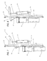
- Figures 1 and 2 illustrate perspective views of a variable position gas trap apparatus 10 utilized to separate gases entrained in drilling fluid 12 in a container or tank 14 (shown by dash lines) wherein the level of the drilling fluid 12 in the tank 14 varies.
- Various hoses which are a part of the apparatus are not shown in Figures 1 and 2 for clarity.
- the present invention provides automatic height adjustment in response to changes in the surface level of drilling fluid 12 in the tank 14.
- the variable position apparatus 10 includes a gas trap container 16 having an open base and a motor 18 wherein the motor 18 rotates a shaft 24. Extending from the shaft 24 is a stirrer 32 which extends into the gas trap container 16 to stir the drilling fluid and assist in releasing gases contained within the drilling fluid 12.
- a gas trap container 16 having an open base and a motor 18 wherein the motor 18 rotates a shaft 24. Extending from the shaft 24 is a stirrer 32 which extends into the gas trap container 16 to stir the drilling fluid and assist in releasing gases contained within the drilling fluid 12.
- a stirrer 32 which extends into the gas trap container 16 to stir the drilling fluid and assist in releasing gases contained within the drilling fluid 12.
- Various designs and configurations of known gas trap containers might be utilized.
- an electric motor 18 might be employed or, alternatively, a pneumatic or other type of motor might be used within the spirit and scope of the present invention.
- the gas trap container 16 and the motor 18 are attached to a carriage 20 which is substantially parallel to the wall or walls of the tank 14 and substantially perpendicular to the level of the drilling fluid 12 in the tank.
- the gas trap container 16 and the motor 18 may be attached to the carriage by fasteners, by welding, or by other mechanism.
- the carriage 20 includes a pair of parallel hollow guide tubes 22 and 23.
- the variable position gas trap apparatus 10 also includes a frame 26.
- the frame 26 is attached to the tank 14 in any of a variety of manners.
- the frame 26 includes a pair of parallel guide rods 28 and 30.
- the guide rods are substantially parallel to the wall or walls of the tank 14 and substantially perpendicular to the level of the drilling fluid 12 in the tank.
- the guide tubes of the carriage are coaxial with the guide rods of the frame.
- Each of the guide tubes 22 and 23 on the carriage 20 has an inside diameter slightly larger than the outside diameter of each of the guide rods 28 and 30. Accordingly, the guide tubes and the accompanying carriage 20 are permitted to travel and ride along the guide rods 28 and 30 of the frame 26.
- buoyant float 34 which will float on the drilling fluid 12 in the tank 14.
- the buoyant float may take the form of a hollow sphere. Extending from the buoyant float 34 is an extending float rod 36.
- Figure 3 illustrates a perspective view of the gas trap apparatus 10 apart from the mud tank 14 and drilling fluid 12 and Figure 4 illustrates a side view of the apparatus 10 partially cut away for ease of viewing.
- the buoyant float 34 may be surrounded by an optional shroud 38 to prevent the float from being damaged.
- the extending float rod 36 passes through a float rod cover 40.
- the gases will rise to the top of the container 16 and be permitted to pass through a port 42 (visible in Figure 4 ) and thereafter delivered through a line 44 to an analyzer 46 (shown in dashed lines) or other similar equipment, which may in turn, be connected with and operate with certain computer equipment 48, all as is well known.
- the carriage 20 and the accompanying gas trap container 16 and motor 18 are moved with respect to the frame by action of a cylinder 50, which may be powered by pneumatic power supplied from a pneumatic system 52.
- the cylinder 50 might be powered by hydraulics or by an electric motor (not shown).
- One end of the cylinder 50 is pivotally attached to the frame 26 through an extending ear 54.
- the opposite end of the cylinder 50 is connected to the carriage 20, as will be described, through an extending ram or piston 56.
- the piston 56 is pivotally connected to a lever arm 58.
- the lever arm 58 is also connected at a first end which acts as a lever point to the frame 26 at a cantilever arm 60.
- Another end of the lever arm 58 opposed to the first end is pivotally attached to the carriage 20 through a pivotal link 62.
- a chain or other connection might alternately be utilized.
- Figure 5 illustrates the action of the apparatus 10 in response to a rising level of drilling fluid 12.
- Figure 6 illustrates the action of the apparatus 10 in response to a decrease in the level of the drilling fluid 12.
- the buoyant float 34 will likewise move upward as illustrated by arrow 72. This will cause the extending float rod 36 to likewise move upward within the float rod cover which will move a lever 74 as illustrated by arrow 76.
- the lever 74 will cause activation of a four-way control valve 78 (having five ports) to permit the pneumatic system 52 to activate the cylinder 50 (not visible), causing the piston 56 to extend.
- the extension of the piston 56 moves the lever arm 58, thereby raising the carriage 20 which, in turn, raises the gas trap container 16 and the actuator valve 78.
- valves For example, a two way valve (with 3 ports) might be employed with gravity used to move the carriage downward.
- Figures 7 and 8 are side views of the apparatus 10 illustrating the mechanism to move the carriage with respect to the frame and, in particular, the linkage of the various constituent elements.
- the cylinder 50 is pivotally connected to the ear 54 extending from the frame 26.
- the piston 56 extending from the cylinder 50 is shown in an extended position in Figure 8 .
- the lever arm 58 pivots about the pivot point at the connection with the cantilever arm 60.
- the lever arm 56 is raised thereby raising the carriage through its connection with the link 62.
- the present invention provides a feedback control loop which activates a mechanical apparatus resulting in automatic adjustment of the level of the gas trap.
- Figure 9 illustrates a side view of a second, preferred embodiment 90 of the variable position gas trap apparatus.
- the embodiment 90 in Figure 9 will operate in response to changing fluid levels as previously described.
- a gas trap container 92 and motor 94 are attached to a carriage 96 which moves with respect to a frame 98 as previously described.
- a cylinder 100 is pivotally attached to the frame at an extending ear 102.
- a piston 104 is moved as shown by arrow 106, a cable, rope or wire 108 which is engaged with a pulley 110 moves the carriage 96, thereby raising or lowering the gas trap container 92.
- buoyant float and control valve are not shown in Figure 9 for clarity.
- the present invention provides a feedback control loop which activates a mechanical apparatus resulting in automatic adjustment of the level of the gas trap.
- Figure 10 illustrates a further, third preferred embodiment 120 of the variable position gas trap apparatus.
- a gas trap container 114 and motor 116 are mounted on a carriage 118 as previously described in detail in the first embodiment.
- a donut style float 122 surrounds a magnetic sensor pole 124 so that the position of the donut float 122 changes as the level of the drilling fluid in the tank changes. The level of the drilling fluid in the tank is sensed by the magnetic sensor 124. This information is electronically relayed to a control valve 130.
- the magnetic sensor and the control valve may be in communication with a computer 132. Alternately, the donut style float 122 might be designed with the magnetic sensor contained therein.
- the present invention provides a feedback control loop which activates a mechanical apparatus resulting in automatic adjustment of the level of the gas trap.
- Figures 11 , 12 and 13 illustrates a further, fourth preferred embodiment of an apparatus 150 for a variable position gas trap.
- a gas trap container 134 and a motor 136 are mounted on a carriage 138 as previously described in detail.
- a pneumatic air supply (shown by dashed lines 152) provides a constant pressure through a splitter 148 connected to line 164 to a hollow sensing tube 154 which is partially submerged in the drilling fluid. The pneumatic air supply will slowly force air bubbles from the sensing tube 154.
- Extension of a piston (not shown) of the cylinder will move a lever arm to cause the carriage and the accompanying gas trap container and motor to rise, as previously described in detail.
- Figures 12 and 13 illustrate an example of a five port, four way valve 158 shown in two extreme, opposed positions.
- air pressure is supplied from pneumatic air supply 152 through a line 172 to top of a spool 168 which is opposed to the force from connecting rod 162.
- the spool 168 In position shown in Figure 12 , the spool 168 will direct air pressure to the cylinder to raise the carriage, whereas in position in Figure 13 , the spool will direct air pressure to the cylinder to lower the carriage.
- the present invention provides a feedback control loop which activates a mechanical apparatus resulting in automatic adjustment of the level of the gas trap.
Landscapes
- Engineering & Computer Science (AREA)
- Life Sciences & Earth Sciences (AREA)
- Geology (AREA)
- Mining & Mineral Resources (AREA)
- Physics & Mathematics (AREA)
- Environmental & Geological Engineering (AREA)
- Fluid Mechanics (AREA)
- General Life Sciences & Earth Sciences (AREA)
- Geochemistry & Mineralogy (AREA)
- Mechanical Engineering (AREA)
- Earth Drilling (AREA)
- Filling Or Discharging Of Gas Storage Vessels (AREA)
Description
- The present invention is directed to a variable position gas trap apparatus and method used to separate gases entrained in drilling fluid in a tank. In particular, the present invention is directed to a variable position gas trap apparatus wherein a feedback control loop mechanically and automatically adjusts the height of the gas trap in response to changes in the level of the drilling fluid in the tank.
- The use of drilling fluid or fluids while drilling subterranean wells is well-known. The drilling fluid or fluids may be aqueous-based, but are most often hydrocarbon or petroleum-based. The drilling fluids are referred to as base fluid, drilling mud or, simply, mud. Drilling fluid is used for a number of reasons. The drilling fluid is pumped downhole to the site where the drill bit is operating and is used to carry dirt, debris, rocks and chips broken off by action of the drill bit. The drilling fluid also assists in cooling the area where the drill bit operates. The drilling fluid may contain other additives, such as special lubricants, and is relatively expensive.
- The drilling fluid is typically contained in a closed looped system. Upon return to the surface from downhole, the drilling fluid is often processed with a vibrating shaker or "shale shaker" which contains a screen so that the drilling fluid passes through the screen while rocks or other items above a certain size are separated out. The drilling fluid is stored in an open container or tank or a series of containers and then returned back down hole in a continuous system.
- It has been discovered that the drilling fluid which returns from the downhole drilling location will return with downhole gas bubbles. The content of these gas bubbles provides extremely valuable information on the presence of hydrocarbons, such as natural gas. Monitoring of the gas content and composition as a function of depth is sometimes referred to as "mud logging".
- Assignee's
U.S. Patent No. 7,210,342 entitled "Method and Apparatus for Determining Gas Content of Subsurface Fluids for Oil and Gas Exploration" discloses one example of a system to analyze the gas content of bubbles entrained within the drilling fluid. - Over the years, there have been various devices that have been developed to liberate the gas bubbles which are entrained in the drilling fluid. Zamfes (
U.S. Patent No. 6,389,878 ) shows one example of a gas trap. A canister or container is partially submerged in the drilling fluid in the mud tank and permits drilling mud to enter from the base and exit from a side. The gas trap includes a motor which rotates a blade or stirrer to assist in releasing gas bubbles which are then taken to a gas collection port for analysis. - There are various types of gas traps, but most of them operate on similar basic principles. The gas traps are strapped or otherwise secured inside of the drilling mud tank. Changes in the operation of the drilling equipment or the drilling fluid pump can alter the level of fluid in the tank. If the drilling mud level in the tank or container changes, the operation of the gas trap may be affected. If the level of the drilling mud is too low, not enough mud will enter the gas trap, so that primarily atmospheric air will enter the gas trap. If the level of drilling fluid is too high, it may affect the efficiency of separation of the gas bubbles from the drilling fluid or, in an extreme case, mud may enter the analysis equipment. While it is possible to manually move the gas trap in response to changes in the level, there is an ongoing effort to minimize required personnel at a drilling location.
- Prior devices include Ratcliff (
U.S. Patent No. 4,358,298 ) which discloses a rack gear 66 that operates with a pinion gear 86 so that manual rotation of acrank 90 permits vertical adjustment of the gas trap. No automatic adjustment is provided. -
Anderson (U.S. Patent 3.055.743 ) discloses a similar arrangement. -
Naess (U.S. Patent No. 4,447,247 ) discloses a submerged mechanism to collect gas flowing into a body of water with an upper member 2 and ballast tanks 13 for adjusting the displacement of the upper member in an underwater blow-out. - Also in the past, a standard gas trap has been encapsulated in a buoyant sheath without any feedback control loop or mechanical assistance to respond to changes in the mud level. Despite the simplicity, the large footprint comprises its utility.
- Notwithstanding the foregoing, it is desirable to provide a variable position gas trap apparatus wherein the position of the gas trap will automatically vary with the level of the mud in the tank.
- It is also desirable to provide an apparatus that will operate with a wide variety of existing gas trap designs.
- It is also desirable to provide a variable position gas trap apparatus having a feedback control loop for height adjustment.
- It is also desirable to provide a variable position gas trap that is compact in design and reliable in operation.
- The present invention provides a variable position gas trap apparatus utilized to separate gases which are entrained in drilling fluid in a container or a tank. The present invention provides for automatic and especially mechanical height adjustment in response to surface level change of the drilling fluid.
- The apparatus operates with and includes a gas trap container having an open base and a motor wherein the motor rotates a shaft. Extending from the shaft is a stirrer which extends into the gas trap container to stir the drilling fluid and assists in releasing gases contained within the drilling fluid. The gas trap container and the motor are attached to a carriage which is substantially parallel to a wall or walls of the tank and substantially perpendicular to the level of the drilling fluid. The carriage includes a pair of parallel guide tubes.
- The variable position gas trap apparatus also includes a frame attached to the tank. The frame includes a pair of parallel guide rods which are substantially parallel to the wall or walls of the tank and substantially perpendicular to the level of the drilling fluid in the tank.
- The guide tubes of the carriage are coaxial with the guide rods of the frame so that the guide tubes and accompanying carriage are permitted to travel and ride along the guide rods of the frame. In one embodiment, a buoyant float is attached to the carriage. Extending from the buoyant float is an extending float rod which passes through a float rod cover.
- The carriage and the accompanying gas trap container and motor are moved with respect to the frame by action of a cylinder. One end of the cylinder is pivotally attached to the frame and the opposite end of the cylinder is connected to the carriage through an extending ram or piston.
- As the level of drilling fluid in the tank increases, the buoyant float will likewise move upward which will cause the extending float rod to move upward and will move a lever to cause activation of a control valve to activate the cylinder causing the piston to extend. The extension of the piston raises the gas trap container.
-
-
Figures 1 and 2 illustrate perspective views of an initial preferred embodiment of a variable position gas trap apparatus constructed in accordance with the present invention in a tank (shown by dashed lines) wherein the level of the drilling fluid in the tank varies; -
Figure 3 illustrates a perspective view of the variable position gas trap apparatus shown inFigures 1 and 2 apart from the tank and the drilling fluid; -
Figure 4 illustrates a side view of the apparatus shown inFigures 1 through 3 partially cut away for ease of viewing; -
Figure 5 illustrates the action of the variable position gas trap apparatus in response to a rising level of drilling fluid whileFigure 6 illustrates the action of the apparatus in response to a decrease in the level of the drilling fluid; -
Figures 7 and 8 illustrate portions of the variable position gas trap apparatus to illustrate the linkage of the various component elements; -
Figure 9 illustrates a second preferred embodiment of the variable position gas trap apparatus of the present invention; -
Figure 10 illustrates a third preferred embodiment of the variable position gas trap apparatus of the present invention; -
Figure 11 illustrates a fourth preferred embodiment of the variable position gas trap apparatus of the present invention; and -
Figures 12 and 13 illustrate an example of operation of a four way valve utilized with the present invention. - The embodiments discussed herein are merely illustrative of specific manners in which to make and use the invention and are not to be interpreted as limiting the scope of the instant invention.
- While the invention has been described with a certain degree of particularity, it is to be noted that many modifications may be made in the details of the invention's construction and the arrangement of its components without departing from the spirit and scope of this disclosure. It is understood that the invention is not limited to the embodiments set forth herein for purposes of exemplification.
- Referring to the drawings in detail,
Figures 1 and 2 illustrate perspective views of a variable positiongas trap apparatus 10 utilized to separate gases entrained indrilling fluid 12 in a container or tank 14 (shown by dash lines) wherein the level of thedrilling fluid 12 in thetank 14 varies. Various hoses which are a part of the apparatus are not shown inFigures 1 and 2 for clarity. - The present invention provides automatic height adjustment in response to changes in the surface level of
drilling fluid 12 in thetank 14. - The
variable position apparatus 10 includes agas trap container 16 having an open base and amotor 18 wherein themotor 18 rotates ashaft 24. Extending from theshaft 24 is astirrer 32 which extends into thegas trap container 16 to stir the drilling fluid and assist in releasing gases contained within thedrilling fluid 12. Various designs and configurations of known gas trap containers might be utilized. - It will be understood that an
electric motor 18 might be employed or, alternatively, a pneumatic or other type of motor might be used within the spirit and scope of the present invention. - The
gas trap container 16 and themotor 18 are attached to acarriage 20 which is substantially parallel to the wall or walls of thetank 14 and substantially perpendicular to the level of thedrilling fluid 12 in the tank. Thegas trap container 16 and themotor 18 may be attached to the carriage by fasteners, by welding, or by other mechanism. In a preferred embodiment, thecarriage 20 includes a pair of parallelhollow guide tubes - The variable position
gas trap apparatus 10 also includes aframe 26. Theframe 26 is attached to thetank 14 in any of a variety of manners. Theframe 26 includes a pair ofparallel guide rods tank 14 and substantially perpendicular to the level of thedrilling fluid 12 in the tank. - The guide tubes of the carriage are coaxial with the guide rods of the frame. Each of the
guide tubes carriage 20 has an inside diameter slightly larger than the outside diameter of each of theguide rods carriage 20 are permitted to travel and ride along theguide rods frame 26. - Also attached to the
carriage 20 is abuoyant float 34, which will float on thedrilling fluid 12 in thetank 14. The buoyant float may take the form of a hollow sphere. Extending from thebuoyant float 34 is an extendingfloat rod 36. -
Figure 3 illustrates a perspective view of thegas trap apparatus 10 apart from themud tank 14 anddrilling fluid 12 andFigure 4 illustrates a side view of theapparatus 10 partially cut away for ease of viewing. Thebuoyant float 34 may be surrounded by anoptional shroud 38 to prevent the float from being damaged. The extendingfloat rod 36 passes through afloat rod cover 40. - As gases are liberated from the
drilling fluid 12, the gases will rise to the top of thecontainer 16 and be permitted to pass through a port 42 (visible inFigure 4 ) and thereafter delivered through aline 44 to an analyzer 46 (shown in dashed lines) or other similar equipment, which may in turn, be connected with and operate withcertain computer equipment 48, all as is well known. - The
carriage 20 and the accompanyinggas trap container 16 andmotor 18 are moved with respect to the frame by action of acylinder 50, which may be powered by pneumatic power supplied from apneumatic system 52. Alternatively, thecylinder 50 might be powered by hydraulics or by an electric motor (not shown). - One end of the
cylinder 50 is pivotally attached to theframe 26 through an extendingear 54. The opposite end of thecylinder 50 is connected to thecarriage 20, as will be described, through an extending ram orpiston 56. In the first preferred embodiment, thepiston 56 is pivotally connected to alever arm 58. Thelever arm 58 is also connected at a first end which acts as a lever point to theframe 26 at acantilever arm 60. - Another end of the
lever arm 58 opposed to the first end is pivotally attached to thecarriage 20 through apivotal link 62. A chain or other connection might alternately be utilized. - It is desirable to retain the
gas trap container 16 partially submerged in the drilling fluid.Figure 5 illustrates the action of theapparatus 10 in response to a rising level ofdrilling fluid 12.Figure 6 illustrates the action of theapparatus 10 in response to a decrease in the level of thedrilling fluid 12. - Referring to
Figure 5 , as the level ofdrilling fluid 12 in thetank 14 increases as illustrated byarrows 70, thebuoyant float 34 will likewise move upward as illustrated byarrow 72. This will cause the extendingfloat rod 36 to likewise move upward within the float rod cover which will move alever 74 as illustrated byarrow 76. Thelever 74 will cause activation of a four-way control valve 78 (having five ports) to permit thepneumatic system 52 to activate the cylinder 50 (not visible), causing thepiston 56 to extend. The extension of thepiston 56 moves thelever arm 58, thereby raising thecarriage 20 which, in turn, raises thegas trap container 16 and theactuator valve 78. - It will also be understood that the invention will work with other valves. For example, a two way valve (with 3 ports) might be employed with gravity used to move the carriage downward.
- Conversely, as seen in
Figure 6 , when the level of thedrilling fluid 12 decreases, as shown byarrows 80, thebuoyant float 34 will likewise move downward as illustrated byarrow 82. This will cause the extendingfloat rod 36 to likewise move downward within the float rod cover which will move thelever 74 as illustrated byarrow 84. Thelever 74 will cause activation of a four-way control valve 78 to permit thepneumatic system 52 to activate the cylinder 50 (not visible) causing thepiston 56 of thecylinder 50 to retract. The retraction of thepiston 56 moves thelever arm 58 which is connected to the carriage through the lever arm and link 62, thereby permitting thecarriage 20 to lower thegas trap container 16. -
Figures 7 and 8 are side views of theapparatus 10 illustrating the mechanism to move the carriage with respect to the frame and, in particular, the linkage of the various constituent elements. Thecylinder 50 is pivotally connected to theear 54 extending from theframe 26. Thepiston 56 extending from thecylinder 50 is shown in an extended position inFigure 8 . As thepiston 56 extends, thelever arm 58 pivots about the pivot point at the connection with thecantilever arm 60. As thepiston 56 extends, thelever arm 56 is raised thereby raising the carriage through its connection with thelink 62. - In summary, the present invention provides a feedback control loop which activates a mechanical apparatus resulting in automatic adjustment of the level of the gas trap.
-
Figure 9 illustrates a side view of a second, preferredembodiment 90 of the variable position gas trap apparatus. Theembodiment 90 inFigure 9 will operate in response to changing fluid levels as previously described. Agas trap container 92 andmotor 94 are attached to acarriage 96 which moves with respect to aframe 98 as previously described. Acylinder 100 is pivotally attached to the frame at an extendingear 102. As apiston 104 is moved as shown byarrow 106, a cable, rope orwire 108 which is engaged with apulley 110 moves thecarriage 96, thereby raising or lowering thegas trap container 92. - The buoyant float and control valve are not shown in
Figure 9 for clarity. - In summary, the present invention provides a feedback control loop which activates a mechanical apparatus resulting in automatic adjustment of the level of the gas trap.
-
Figure 10 illustrates a further, thirdpreferred embodiment 120 of the variable position gas trap apparatus. Agas trap container 114 andmotor 116 are mounted on acarriage 118 as previously described in detail in the first embodiment. Adonut style float 122 surrounds amagnetic sensor pole 124 so that the position of thedonut float 122 changes as the level of the drilling fluid in the tank changes. The level of the drilling fluid in the tank is sensed by themagnetic sensor 124. This information is electronically relayed to acontrol valve 130. The magnetic sensor and the control valve may be in communication with acomputer 132. Alternately, thedonut style float 122 might be designed with the magnetic sensor contained therein. - In summary, the present invention provides a feedback control loop which activates a mechanical apparatus resulting in automatic adjustment of the level of the gas trap.
- Finally,
Figures 11 ,12 and 13 illustrates a further, fourth preferred embodiment of anapparatus 150 for a variable position gas trap. Agas trap container 134 and amotor 136 are mounted on acarriage 138 as previously described in detail. A pneumatic air supply (shown by dashed lines 152) provides a constant pressure through asplitter 148 connected toline 164 to ahollow sensing tube 154 which is partially submerged in the drilling fluid. The pneumatic air supply will slowly force air bubbles from thesensing tube 154. - As shown by
Figure 11A , as the level of drilling fluid in the tank increases, the pressure within thesensing tube 154 will increase, as shown byarrow 140, thereby increasing the pressure in adiaphragm 156 connected to thetube 154 through a line orhose 160. The increase in pressure in thediaphragm 156 will activate a connectingrod 162 connected to acontrol valve 158, such as a four-way valve, which works in conjunction with a cylinder (not shown inFigure 11 ) in similar fashion to that described in the first and second embodiments. - Extension of a piston (not shown) of the cylinder will move a lever arm to cause the carriage and the accompanying gas trap container and motor to rise, as previously described in detail.
-
Figures 12 and 13 illustrate an example of a five port, fourway valve 158 shown in two extreme, opposed positions. As shown byarrow 166, air pressure is supplied frompneumatic air supply 152 through aline 172 to top of aspool 168 which is opposed to the force from connectingrod 162. In position shown inFigure 12 , thespool 168 will direct air pressure to the cylinder to raise the carriage, whereas in position inFigure 13 , the spool will direct air pressure to the cylinder to lower the carriage. - In summary, the present invention provides a feedback control loop which activates a mechanical apparatus resulting in automatic adjustment of the level of the gas trap.
- Whereas, the present invention has been described in relation to the drawings attached hereto, it should be understood that other and further modifications, apart from those shown or suggested herein, may be made within the spirit and scope of this invention.
Claims (12)
- A variable position gas trap apparatus (10) to separate gases entrained in drilling fluid (12) in a tank (14), which apparatus comprises:- a gas trap (16) attached to a carriage (20) ;- a frame (26) attached to said tank (14) characterised in that said carriage includes at least one guide tube (22/23) and said frame includes at least one guide rod (28/30) and wherein said guide tube (22/23) is moveable with respect to said guide rod; and in that the apparatus comprises:- a feedback control loop responsive to changes in the level of said drilling fluid in said tank; and- means to mechanically and automatically move said carriage with respect to said frame in response to said feedback control loop.
- A variable position gas trap apparatus as set forth in claim 1 wherein said feedback control loop includes a buoyant float (34) attached to an extending float rod (36) in communication with a control valve.
- A variable position gas trap apparatus as set forth in one of the preceding claims wherein said means to automatically move said carriage with respect to said frame includes a cylinder (50) attached to said frame wherein said cylinder includes an extending piston connected to a lever arm (58) and wherein said lever arm is pivotally attached to said frame (26) so that said cylinder moves said carriage in response to said feedback control loop.
- A variable position gas trap apparatus as set forth in claim 1 wherein said feedback control loop includes a magnetic sensor pole (124), a donut-style float (122), and a control valve (130) in communication with said magnetic sensor pole.
- A variable position gas trap apparatus as set forth in claim 4 wherein said means to automatically move said carriage (20) with respect to said frame (26) includes a cylinder (50) attached to said frame wherein said cylinder includes an extending piston (56) connected to a lever arm (58) and wherein said lever arm is pivotally attached to said frame so that said cylinder moves said carriage in response to said feedback control loop.
- A variable position gas trap apparatus as set forth in claim 1 wherein said feedback control loop includes a sensing tube in fluid communication (154) with a diaphragm (154) which activates a connecting rod (162) connected to a control valve (158).
- A variable position gas trap apparatus (10) as set forth in one of the preceding claims 1, 2 including a motor (18) attached to the carriage (20);
a cylinder (50) attached on one side to said frame which moves said carriage with respect to said frame;
a control valve (78) in communication with said cylinder (50);
a lever (74) movable by a float rod (36), wherein said lever activates said control valve to raise or lower said carriage having said gas trap container attached thereto. - A variable position gas trap as set forth in one of the preceding claims wherein said at least one guide tube (22,23) comprises a pair of parallel guide tubes and wherein said at least one guide rod comprises at pair of parallel guide rods.
- A variable position gas trap as set forth in one of the preceding claims 3 to 8 wherein said at least one guide tube (22/23) and said at least one guide rod (28,30) are coaxial and said at least one guide tube has an inner diameter slightly larger than an outer diameter of said guide rod.
- A variable position gas trap as set forth in claim 7, 8 or 9 wherein said motor rotates a shaft attached to a stirrer which extends into said gas trap.
- A variable position gas trap as set forth in one of the preceding claims 2, 3, 7-10 including a cup or shroud (38) surrounding said buoyant float (34).
- A variable position gas trap as set forth in one of the preceding claims 7 to 11 wherein said control valve is a four-way valve.
Applications Claiming Priority (2)
| Application Number | Priority Date | Filing Date | Title |
|---|---|---|---|
| US11/861,986 US7794527B2 (en) | 2007-09-26 | 2007-09-26 | Variable position gas trap |
| PCT/US2008/009874 WO2009042018A1 (en) | 2007-09-26 | 2008-08-19 | Variable position gas trap |
Publications (2)
| Publication Number | Publication Date |
|---|---|
| EP2201210A1 EP2201210A1 (en) | 2010-06-30 |
| EP2201210B1 true EP2201210B1 (en) | 2015-12-02 |
Family
ID=40090201
Family Applications (1)
| Application Number | Title | Priority Date | Filing Date |
|---|---|---|---|
| EP08795445.9A Not-in-force EP2201210B1 (en) | 2007-09-26 | 2008-08-19 | Variable position gas trap |
Country Status (5)
| Country | Link |
|---|---|
| US (1) | US7794527B2 (en) |
| EP (1) | EP2201210B1 (en) |
| CA (1) | CA2698618C (en) |
| PL (1) | PL2201210T3 (en) |
| WO (1) | WO2009042018A1 (en) |
Families Citing this family (18)
| Publication number | Priority date | Publication date | Assignee | Title |
|---|---|---|---|---|
| US8632625B2 (en) * | 2010-06-17 | 2014-01-21 | Pason Systems Corporation | Method and apparatus for liberating gases from drilling fluid |
| US8584518B2 (en) | 2010-06-30 | 2013-11-19 | Rigsat Communications Inc. | Gas trap for drilling mud having quick-release separable lower section |
| US9528372B2 (en) | 2010-09-10 | 2016-12-27 | Selman and Associates, Ltd. | Method for near real time surface logging of a hydrocarbon or geothermal well using a mass spectrometer |
| US9528367B2 (en) | 2011-02-17 | 2016-12-27 | Selman and Associates, Ltd. | System for near real time surface logging of a geothermal well, a hydrocarbon well, or a testing well using a mass spectrometer |
| US9528366B2 (en) | 2011-02-17 | 2016-12-27 | Selman and Associates, Ltd. | Method for near real time surface logging of a geothermal well, a hydrocarbon well, or a testing well using a mass spectrometer |
| CA2798561C (en) * | 2011-12-12 | 2014-03-25 | Colin Barrett | Apparatus and method for detecting gases conveyed by drilling fluids from subterranean wells |
| WO2013090977A1 (en) * | 2011-12-19 | 2013-06-27 | Nautilus Minerals Pacific Pty Ltd | A delivery method and system |
| US9441430B2 (en) * | 2012-04-17 | 2016-09-13 | Selman and Associates, Ltd. | Drilling rig with continuous gas analysis |
| US9879489B2 (en) | 2013-08-14 | 2018-01-30 | David L. Shanks | Floating gas trap system using agitation |
| CN103480181B (en) * | 2013-09-10 | 2015-04-15 | 国家地质实验测试中心 | Multi-vane anisotropic turbulent flow type low-pressure and self-balancing slurry degassing device |
| USD749137S1 (en) | 2014-08-08 | 2016-02-09 | Floatair Agitator Limited Liability Company | Impeller for fluid agitation |
| EP3165710B1 (en) | 2015-11-05 | 2020-12-23 | Geoservices Equipements SAS | Gas-extraction device and associated analysis assembly and method |
| CN109736731A (en) * | 2017-10-31 | 2019-05-10 | 中石化石油工程技术服务有限公司 | Multi-parameter Combined Tool logging device |
| US10704347B2 (en) | 2018-06-25 | 2020-07-07 | Schlumberger Technology Corporation | Method and apparatus for analyzing gas from drilling fluids |
| CN109113606B (en) * | 2018-11-14 | 2024-01-30 | 上海神开石油科技有限公司 | Self-elevating degassing device |
| US11441368B2 (en) * | 2019-08-20 | 2022-09-13 | Harry L. Burgess | Split-flow degasser |
| CN112523745B (en) * | 2020-12-02 | 2022-07-15 | 中国地质大学(北京) | Low-yield shale gas reservoir production seeking device and method |
| US12222234B2 (en) | 2021-02-08 | 2025-02-11 | Zach CADWALLADER | Isolated industrial float assembly |
Family Cites Families (26)
| Publication number | Priority date | Publication date | Assignee | Title |
|---|---|---|---|---|
| US2489180A (en) * | 1939-04-01 | 1949-11-22 | John T Hayward | Method of detecting gas in well drilling fluids |
| US2429555A (en) * | 1942-08-08 | 1947-10-21 | Cecil T Langford | Method of and apparatus for analyzing gases and vapors absorbed in materials |
| US2748884A (en) * | 1952-06-30 | 1956-06-05 | Salt Water Control Inc | Apparatus for treating drilling mud |
| US3055743A (en) * | 1959-07-06 | 1962-09-25 | Eastman Oil Well Survey Co | Gas detection apparatus |
| US3118738A (en) * | 1960-11-10 | 1964-01-21 | Jersey Prod Res Co | Quantitative drilling mud gas trap |
| US3363404A (en) * | 1964-10-06 | 1968-01-16 | Swaco Inc | Mud degassers |
| US3362136A (en) * | 1965-03-30 | 1968-01-09 | Fluid Control Inc | Apparatus for degassing fluids |
| US4113452A (en) * | 1975-07-31 | 1978-09-12 | Kobe, Inc. | Gas/liquid separator |
| US4084946A (en) * | 1977-05-31 | 1978-04-18 | Burgess Harry L | Drilling mud degasser |
| NO146545C (en) * | 1979-12-21 | 1982-10-20 | Erik B Naess | PROCEDURE AND DEVICE FOR COLLECTION OF OIL AND GAS IN THE SEA, SPECIFICALLY BY AN UNCONTROLLED Blowout at the seabed |
| US4381191A (en) * | 1981-06-24 | 1983-04-26 | Brand Lavoice B | Drilling mud degasser |
| US4358298A (en) * | 1981-09-10 | 1982-11-09 | Ratcliff Elmer G | Motorized gas trap |
| US4565086A (en) * | 1984-01-20 | 1986-01-21 | Baker Drilling Equipment Company | Method and apparatus for detecting entrained gases in fluids |
| US4731732A (en) * | 1985-08-07 | 1988-03-15 | Aluminum Company Of America | Method and apparatus for determining soluble gas content |
| US4833915A (en) * | 1987-12-03 | 1989-05-30 | Conoco Inc. | Method and apparatus for detecting formation hydrocarbons in mud returns, and the like |
| US4887464A (en) * | 1988-11-22 | 1989-12-19 | Anadrill, Inc. | Measurement system and method for quantitatively determining the concentrations of a plurality of gases in drilling mud |
| US5007488A (en) * | 1990-05-16 | 1991-04-16 | Donovan Brothers Incorporated | Drilling nipple gas trap |
| US5199509A (en) * | 1992-02-14 | 1993-04-06 | Texaco Inc. | Controlled gas trap system |
| US5447052A (en) * | 1992-11-23 | 1995-09-05 | Texaco Inc. | Microwave hydrocarbon gas extraction system |
| US5648603A (en) * | 1995-12-04 | 1997-07-15 | Texaco Inc. | Method and apparatus for stabilizing a quantitative measurement gas trap used in a drilling operation |
| CA2270833C (en) * | 1999-04-30 | 2009-11-10 | Kosta Zamfes | Gas trap for drilling mud |
| US6391094B2 (en) * | 2000-07-19 | 2002-05-21 | Daniel A. Ramos | Method and apparatus for removing gas from drilling mud |
| US7210342B1 (en) * | 2001-06-02 | 2007-05-01 | Fluid Inclusion Technologies, Inc. | Method and apparatus for determining gas content of subsurface fluids for oil and gas exploration |
| FR2856609B1 (en) * | 2003-06-27 | 2006-12-15 | Geolog Spa | SYSTEM FOR DEGASSING A LIQUID MEDIUM AND ANALYZING GASES CONTAINED IN THE LIQUID ENVIRONMENT |
| US20060202122A1 (en) * | 2005-03-14 | 2006-09-14 | Gunn Scott E | Detecting gas in fluids |
| US20060254421A1 (en) * | 2005-05-12 | 2006-11-16 | Epoch Well Services, Inc. | Gas trap for drilling mud |
-
2007
- 2007-09-26 US US11/861,986 patent/US7794527B2/en active Active
-
2008
- 2008-08-19 WO PCT/US2008/009874 patent/WO2009042018A1/en not_active Ceased
- 2008-08-19 CA CA2698618A patent/CA2698618C/en not_active Expired - Fee Related
- 2008-08-19 PL PL08795445.9T patent/PL2201210T3/en unknown
- 2008-08-19 EP EP08795445.9A patent/EP2201210B1/en not_active Not-in-force
Also Published As
| Publication number | Publication date |
|---|---|
| EP2201210A1 (en) | 2010-06-30 |
| WO2009042018A1 (en) | 2009-04-02 |
| CA2698618A1 (en) | 2009-04-02 |
| PL2201210T3 (en) | 2016-10-31 |
| CA2698618C (en) | 2013-10-08 |
| US7794527B2 (en) | 2010-09-14 |
| US20090077936A1 (en) | 2009-03-26 |
Similar Documents
| Publication | Publication Date | Title |
|---|---|---|
| EP2201210B1 (en) | Variable position gas trap | |
| US9366118B2 (en) | Processes and systems for treating oil and gas wells | |
| US8561698B2 (en) | Downhole fluid injection | |
| US8905128B2 (en) | Valve assembly employable with a downhole tool | |
| CA2859388C (en) | Floating gas trap system using agitation | |
| CA2686298A1 (en) | Dump bailer | |
| CA2801165C (en) | Methods and apparatus for downhole extraction and analysis of heavy oil | |
| CA2849144A1 (en) | Fluid sample cleanup | |
| US20080236815A1 (en) | Method and apparatus for continous downhole fluid release and well evaluation | |
| NO20101450L (en) | Apparatus and method for collecting fluid in boreholes | |
| US20240279995A1 (en) | Sliding wireline catcher and cutter for lost downhole wire | |
| US9963946B2 (en) | Method of filling a coring tool inner barrel with a coring fluid | |
| US7849917B2 (en) | Marginal oil extraction device | |
| RU2109941C1 (en) | Gear to examine horizontal holes | |
| WO2002064941A1 (en) | Bailer for simultaneously recovery of liquid and gas from a well | |
| US12091969B2 (en) | Subsurface sampling tool | |
| US20040194962A1 (en) | System for retrieving a tubular element from a well | |
| WO2025017374A1 (en) | Drilling unit with selective carbon dioxide and hydrocarbon drilling fluid venting system | |
| JPH0333395A (en) | Boring mechanism for sampling hot spring | |
| US20060008371A1 (en) | Fluid lifting system |
Legal Events
| Date | Code | Title | Description |
|---|---|---|---|
| PUAI | Public reference made under article 153(3) epc to a published international application that has entered the european phase |
Free format text: ORIGINAL CODE: 0009012 |
|
| 17P | Request for examination filed |
Effective date: 20100325 |
|
| AK | Designated contracting states |
Kind code of ref document: A1 Designated state(s): AT BE BG CH CY CZ DE DK EE ES FI FR GB GR HR HU IE IS IT LI LT LU LV MC MT NL NO PL PT RO SE SI SK TR |
|
| AX | Request for extension of the european patent |
Extension state: AL BA MK RS |
|
| DAX | Request for extension of the european patent (deleted) | ||
| GRAP | Despatch of communication of intention to grant a patent |
Free format text: ORIGINAL CODE: EPIDOSNIGR1 |
|
| INTG | Intention to grant announced |
Effective date: 20140905 |
|
| GRAS | Grant fee paid |
Free format text: ORIGINAL CODE: EPIDOSNIGR3 |
|
| GRAA | (expected) grant |
Free format text: ORIGINAL CODE: 0009210 |
|
| AK | Designated contracting states |
Kind code of ref document: B1 Designated state(s): AT BE BG CH CY CZ DE DK EE ES FI FR GB GR HR HU IE IS IT LI LT LU LV MC MT NL NO PL PT RO SE SI SK TR |
|
| REG | Reference to a national code |
Ref country code: GB Ref legal event code: FG4D |
|
| REG | Reference to a national code |
Ref country code: AT Ref legal event code: REF Ref document number: 763724 Country of ref document: AT Kind code of ref document: T Effective date: 20151215 Ref country code: CH Ref legal event code: EP |
|
| REG | Reference to a national code |
Ref country code: IE Ref legal event code: FG4D |
|
| REG | Reference to a national code |
Ref country code: DE Ref legal event code: R096 Ref document number: 602008041450 Country of ref document: DE |
|
| REG | Reference to a national code |
Ref country code: RO Ref legal event code: EPE |
|
| REG | Reference to a national code |
Ref country code: NL Ref legal event code: MP Effective date: 20160302 |
|
| REG | Reference to a national code |
Ref country code: LT Ref legal event code: MG4D |
|
| REG | Reference to a national code |
Ref country code: AT Ref legal event code: MK05 Ref document number: 763724 Country of ref document: AT Kind code of ref document: T Effective date: 20151202 |
|
| PG25 | Lapsed in a contracting state [announced via postgrant information from national office to epo] |
Ref country code: HR Free format text: LAPSE BECAUSE OF FAILURE TO SUBMIT A TRANSLATION OF THE DESCRIPTION OR TO PAY THE FEE WITHIN THE PRESCRIBED TIME-LIMIT Effective date: 20151202 Ref country code: ES Free format text: LAPSE BECAUSE OF FAILURE TO SUBMIT A TRANSLATION OF THE DESCRIPTION OR TO PAY THE FEE WITHIN THE PRESCRIBED TIME-LIMIT Effective date: 20151202 Ref country code: LT Free format text: LAPSE BECAUSE OF FAILURE TO SUBMIT A TRANSLATION OF THE DESCRIPTION OR TO PAY THE FEE WITHIN THE PRESCRIBED TIME-LIMIT Effective date: 20151202 |
|
| RAP2 | Party data changed (patent owner data changed or rights of a patent transferred) |
Owner name: SCHLUMBERGER TECHNOLOGY B.V. (STBV) |
|
| REG | Reference to a national code |
Ref country code: NO Ref legal event code: T2 Effective date: 20151202 |
|
| PG25 | Lapsed in a contracting state [announced via postgrant information from national office to epo] |
Ref country code: NL Free format text: LAPSE BECAUSE OF FAILURE TO SUBMIT A TRANSLATION OF THE DESCRIPTION OR TO PAY THE FEE WITHIN THE PRESCRIBED TIME-LIMIT Effective date: 20151202 Ref country code: LV Free format text: LAPSE BECAUSE OF FAILURE TO SUBMIT A TRANSLATION OF THE DESCRIPTION OR TO PAY THE FEE WITHIN THE PRESCRIBED TIME-LIMIT Effective date: 20151202 Ref country code: AT Free format text: LAPSE BECAUSE OF FAILURE TO SUBMIT A TRANSLATION OF THE DESCRIPTION OR TO PAY THE FEE WITHIN THE PRESCRIBED TIME-LIMIT Effective date: 20151202 Ref country code: SE Free format text: LAPSE BECAUSE OF FAILURE TO SUBMIT A TRANSLATION OF THE DESCRIPTION OR TO PAY THE FEE WITHIN THE PRESCRIBED TIME-LIMIT Effective date: 20151202 Ref country code: GR Free format text: LAPSE BECAUSE OF FAILURE TO SUBMIT A TRANSLATION OF THE DESCRIPTION OR TO PAY THE FEE WITHIN THE PRESCRIBED TIME-LIMIT Effective date: 20160303 Ref country code: FI Free format text: LAPSE BECAUSE OF FAILURE TO SUBMIT A TRANSLATION OF THE DESCRIPTION OR TO PAY THE FEE WITHIN THE PRESCRIBED TIME-LIMIT Effective date: 20151202 |
|
| PG25 | Lapsed in a contracting state [announced via postgrant information from national office to epo] |
Ref country code: IS Free format text: LAPSE BECAUSE OF FAILURE TO SUBMIT A TRANSLATION OF THE DESCRIPTION OR TO PAY THE FEE WITHIN THE PRESCRIBED TIME-LIMIT Effective date: 20151202 |
|
| PG25 | Lapsed in a contracting state [announced via postgrant information from national office to epo] |
Ref country code: CZ Free format text: LAPSE BECAUSE OF FAILURE TO SUBMIT A TRANSLATION OF THE DESCRIPTION OR TO PAY THE FEE WITHIN THE PRESCRIBED TIME-LIMIT Effective date: 20151202 |
|
| PG25 | Lapsed in a contracting state [announced via postgrant information from national office to epo] |
Ref country code: PT Free format text: LAPSE BECAUSE OF FAILURE TO SUBMIT A TRANSLATION OF THE DESCRIPTION OR TO PAY THE FEE WITHIN THE PRESCRIBED TIME-LIMIT Effective date: 20160404 Ref country code: SK Free format text: LAPSE BECAUSE OF FAILURE TO SUBMIT A TRANSLATION OF THE DESCRIPTION OR TO PAY THE FEE WITHIN THE PRESCRIBED TIME-LIMIT Effective date: 20151202 Ref country code: EE Free format text: LAPSE BECAUSE OF FAILURE TO SUBMIT A TRANSLATION OF THE DESCRIPTION OR TO PAY THE FEE WITHIN THE PRESCRIBED TIME-LIMIT Effective date: 20151202 Ref country code: IS Free format text: LAPSE BECAUSE OF FAILURE TO SUBMIT A TRANSLATION OF THE DESCRIPTION OR TO PAY THE FEE WITHIN THE PRESCRIBED TIME-LIMIT Effective date: 20160402 |
|
| REG | Reference to a national code |
Ref country code: DE Ref legal event code: R097 Ref document number: 602008041450 Country of ref document: DE |
|
| PLBE | No opposition filed within time limit |
Free format text: ORIGINAL CODE: 0009261 |
|
| STAA | Information on the status of an ep patent application or granted ep patent |
Free format text: STATUS: NO OPPOSITION FILED WITHIN TIME LIMIT |
|
| PG25 | Lapsed in a contracting state [announced via postgrant information from national office to epo] |
Ref country code: DK Free format text: LAPSE BECAUSE OF FAILURE TO SUBMIT A TRANSLATION OF THE DESCRIPTION OR TO PAY THE FEE WITHIN THE PRESCRIBED TIME-LIMIT Effective date: 20151202 |
|
| PGFP | Annual fee paid to national office [announced via postgrant information from national office to epo] |
Ref country code: GB Payment date: 20160824 Year of fee payment: 9 Ref country code: IT Payment date: 20160809 Year of fee payment: 9 Ref country code: NO Payment date: 20160810 Year of fee payment: 9 |
|
| 26N | No opposition filed |
Effective date: 20160905 |
|
| PG25 | Lapsed in a contracting state [announced via postgrant information from national office to epo] |
Ref country code: SI Free format text: LAPSE BECAUSE OF FAILURE TO SUBMIT A TRANSLATION OF THE DESCRIPTION OR TO PAY THE FEE WITHIN THE PRESCRIBED TIME-LIMIT Effective date: 20151202 |
|
| PGFP | Annual fee paid to national office [announced via postgrant information from national office to epo] |
Ref country code: PL Payment date: 20160802 Year of fee payment: 9 Ref country code: RO Payment date: 20160801 Year of fee payment: 9 |
|
| PG25 | Lapsed in a contracting state [announced via postgrant information from national office to epo] |
Ref country code: BE Free format text: LAPSE BECAUSE OF FAILURE TO SUBMIT A TRANSLATION OF THE DESCRIPTION OR TO PAY THE FEE WITHIN THE PRESCRIBED TIME-LIMIT Effective date: 20151202 |
|
| REG | Reference to a national code |
Ref country code: DE Ref legal event code: R119 Ref document number: 602008041450 Country of ref document: DE |
|
| PG25 | Lapsed in a contracting state [announced via postgrant information from national office to epo] |
Ref country code: MC Free format text: LAPSE BECAUSE OF FAILURE TO SUBMIT A TRANSLATION OF THE DESCRIPTION OR TO PAY THE FEE WITHIN THE PRESCRIBED TIME-LIMIT Effective date: 20151202 |
|
| REG | Reference to a national code |
Ref country code: CH Ref legal event code: PL |
|
| PG25 | Lapsed in a contracting state [announced via postgrant information from national office to epo] |
Ref country code: CH Free format text: LAPSE BECAUSE OF NON-PAYMENT OF DUE FEES Effective date: 20160831 Ref country code: LI Free format text: LAPSE BECAUSE OF NON-PAYMENT OF DUE FEES Effective date: 20160831 |
|
| REG | Reference to a national code |
Ref country code: FR Ref legal event code: ST Effective date: 20170428 |
|
| REG | Reference to a national code |
Ref country code: IE Ref legal event code: MM4A |
|
| PG25 | Lapsed in a contracting state [announced via postgrant information from national office to epo] |
Ref country code: DE Free format text: LAPSE BECAUSE OF NON-PAYMENT OF DUE FEES Effective date: 20170301 Ref country code: IE Free format text: LAPSE BECAUSE OF NON-PAYMENT OF DUE FEES Effective date: 20160819 Ref country code: FR Free format text: LAPSE BECAUSE OF NON-PAYMENT OF DUE FEES Effective date: 20160831 |
|
| PG25 | Lapsed in a contracting state [announced via postgrant information from national office to epo] |
Ref country code: LU Free format text: LAPSE BECAUSE OF NON-PAYMENT OF DUE FEES Effective date: 20160819 |
|
| REG | Reference to a national code |
Ref country code: NO Ref legal event code: MMEP |
|
| GBPC | Gb: european patent ceased through non-payment of renewal fee |
Effective date: 20170819 |
|
| PG25 | Lapsed in a contracting state [announced via postgrant information from national office to epo] |
Ref country code: RO Free format text: LAPSE BECAUSE OF NON-PAYMENT OF DUE FEES Effective date: 20170819 Ref country code: NO Free format text: LAPSE BECAUSE OF NON-PAYMENT OF DUE FEES Effective date: 20170831 |
|
| PG25 | Lapsed in a contracting state [announced via postgrant information from national office to epo] |
Ref country code: HU Free format text: LAPSE BECAUSE OF FAILURE TO SUBMIT A TRANSLATION OF THE DESCRIPTION OR TO PAY THE FEE WITHIN THE PRESCRIBED TIME-LIMIT; INVALID AB INITIO Effective date: 20080819 Ref country code: CY Free format text: LAPSE BECAUSE OF FAILURE TO SUBMIT A TRANSLATION OF THE DESCRIPTION OR TO PAY THE FEE WITHIN THE PRESCRIBED TIME-LIMIT Effective date: 20151202 |
|
| PG25 | Lapsed in a contracting state [announced via postgrant information from national office to epo] |
Ref country code: TR Free format text: LAPSE BECAUSE OF FAILURE TO SUBMIT A TRANSLATION OF THE DESCRIPTION OR TO PAY THE FEE WITHIN THE PRESCRIBED TIME-LIMIT Effective date: 20151202 Ref country code: MT Free format text: LAPSE BECAUSE OF NON-PAYMENT OF DUE FEES Effective date: 20160831 |
|
| PG25 | Lapsed in a contracting state [announced via postgrant information from national office to epo] |
Ref country code: GB Free format text: LAPSE BECAUSE OF NON-PAYMENT OF DUE FEES Effective date: 20170819 Ref country code: BG Free format text: LAPSE BECAUSE OF FAILURE TO SUBMIT A TRANSLATION OF THE DESCRIPTION OR TO PAY THE FEE WITHIN THE PRESCRIBED TIME-LIMIT Effective date: 20151202 |
|
| PG25 | Lapsed in a contracting state [announced via postgrant information from national office to epo] |
Ref country code: IT Free format text: LAPSE BECAUSE OF NON-PAYMENT OF DUE FEES Effective date: 20170819 |
|
| PG25 | Lapsed in a contracting state [announced via postgrant information from national office to epo] |
Ref country code: PL Free format text: LAPSE BECAUSE OF NON-PAYMENT OF DUE FEES Effective date: 20170819 |
|
| P01 | Opt-out of the competence of the unified patent court (upc) registered |
Effective date: 20230526 |