EP2200762B1 - Method and apparatus for discharging a non-linear cryogen spray across the width of a mill stand - Google Patents
Method and apparatus for discharging a non-linear cryogen spray across the width of a mill stand Download PDFInfo
- Publication number
- EP2200762B1 EP2200762B1 EP08798811.9A EP08798811A EP2200762B1 EP 2200762 B1 EP2200762 B1 EP 2200762B1 EP 08798811 A EP08798811 A EP 08798811A EP 2200762 B1 EP2200762 B1 EP 2200762B1
- Authority
- EP
- European Patent Office
- Prior art keywords
- cryogenic cooling
- cooling device
- cryogenic
- throttling gas
- gas supply
- Prior art date
- Legal status (The legal status is an assumption and is not a legal conclusion. Google has not performed a legal analysis and makes no representation as to the accuracy of the status listed.)
- Not-in-force
Links
Images


Classifications
-
- B—PERFORMING OPERATIONS; TRANSPORTING
- B21—MECHANICAL METAL-WORKING WITHOUT ESSENTIALLY REMOVING MATERIAL; PUNCHING METAL
- B21B—ROLLING OF METAL
- B21B27/00—Rolls, roll alloys or roll fabrication; Lubricating, cooling or heating rolls while in use
- B21B27/06—Lubricating, cooling or heating rolls
- B21B27/10—Lubricating, cooling or heating rolls externally
-
- B—PERFORMING OPERATIONS; TRANSPORTING
- B21—MECHANICAL METAL-WORKING WITHOUT ESSENTIALLY REMOVING MATERIAL; PUNCHING METAL
- B21B—ROLLING OF METAL
- B21B37/00—Control devices or methods specially adapted for metal-rolling mills or the work produced thereby
- B21B37/74—Temperature control, e.g. by cooling or heating the rolls or the product
-
- B—PERFORMING OPERATIONS; TRANSPORTING
- B21—MECHANICAL METAL-WORKING WITHOUT ESSENTIALLY REMOVING MATERIAL; PUNCHING METAL
- B21B—ROLLING OF METAL
- B21B45/00—Devices for surface or other treatment of work, specially combined with or arranged in, or specially adapted for use in connection with, metal-rolling mills
- B21B45/02—Devices for surface or other treatment of work, specially combined with or arranged in, or specially adapted for use in connection with, metal-rolling mills for lubricating, cooling, or cleaning
- B21B45/0203—Cooling
- B21B45/0206—Coolants
-
- B—PERFORMING OPERATIONS; TRANSPORTING
- B21—MECHANICAL METAL-WORKING WITHOUT ESSENTIALLY REMOVING MATERIAL; PUNCHING METAL
- B21B—ROLLING OF METAL
- B21B45/00—Devices for surface or other treatment of work, specially combined with or arranged in, or specially adapted for use in connection with, metal-rolling mills
- B21B45/02—Devices for surface or other treatment of work, specially combined with or arranged in, or specially adapted for use in connection with, metal-rolling mills for lubricating, cooling, or cleaning
- B21B45/0203—Cooling
- B21B45/0209—Cooling devices, e.g. using gaseous coolants
- B21B2045/0212—Cooling devices, e.g. using gaseous coolants using gaseous coolants
-
- B—PERFORMING OPERATIONS; TRANSPORTING
- B21—MECHANICAL METAL-WORKING WITHOUT ESSENTIALLY REMOVING MATERIAL; PUNCHING METAL
- B21B—ROLLING OF METAL
- B21B45/00—Devices for surface or other treatment of work, specially combined with or arranged in, or specially adapted for use in connection with, metal-rolling mills
- B21B45/02—Devices for surface or other treatment of work, specially combined with or arranged in, or specially adapted for use in connection with, metal-rolling mills for lubricating, cooling, or cleaning
- B21B45/0203—Cooling
- B21B45/0209—Cooling devices, e.g. using gaseous coolants
- B21B45/0215—Cooling devices, e.g. using gaseous coolants using liquid coolants, e.g. for sections, for tubes
Definitions
- the present invention is directed to the use of cryogenic spay devices in cold rolling processes, as well as other industrial applications, such as hot and profile rolling and thermal spray coating of cylindrical shapes, see method (claim 1) and corresponding apparatus (claim 11).
- Cold rolling is a process used to produce metallic sheet or strip with specific mechanical properties such as surface finish and dimensional tolerances.
- the metallic sheet or strip (rolled product) passes between two counter-rotating work rolls adjusted at a predetermined roll gap so that the rolled product is plastically deformed to a required thickness defined by the selected gap setting.
- Cold rolling generates heat in response to the forces required to deform the strip and friction between the work rolls and the rolled product. This generated heat accumulates in both the work rolls and rolled product, and it must be dissipated to maintain mill stand temperature at acceptable cold rolling levels.
- Cold rolling temperatures are normally above about 120° C in a cold reduction mill, and about 205° C in a high-speed cold tandem mill. Excessive rolling temperatures adversely affect the rolled product properties, causing surface oxidation, defects in surface quality, and inconsistent gauge, shape, and flatness, hereinafter referred to as "product shape.”
- cryogenic and non-cryogenic cooling devices have been used to keep strip and work roll temperatures within acceptable ranges.
- attempts have been made to keep mill temperatures within a desired range by varying the overall intensity of a uniform cryogenic spray profile based on data received from optical pyrometers directed at a roll surface.
- EP 0 136 921 A2 which is considered to represent the closest prior art of the present application, discloses a rolling mill for rolling metal strip 15, comprising a shape sensor for giving an indication of strip 15 shape by detecting widthwise variations in tension in the strip 15, a temperature sensor upstream of the shape sensor for detecting widthwise temperature variations in the strip 15, and means for applying coolant to the strip 15 for differentially cooling the strip 15 across its width to reduce those temperature variations prior to arrival of the strip 15 at the shape sensor.
- row of spray nozzles is arranged beneath the strip 15, across the width of the strip 15.
- the spray nozzles are mounted on a coolant manifold.
- Each spray nozzle 35 has a supply conduit 43 which has an opening 44 in the manifold 42.
- the opening 44 can be closed by pneumatically controlled diaphragm valve 45.
- a flexible diaphragm 46 is mounted adjacent the opening 44.
- a chamber 47 Behind the diaphragm 46 is a chamber 47 which can be selectively connected to a source of pressurized air which will, when applied, sufficiently deform the diaphragm 46 to close the opening 44.
- coolant under pressure supplied in manifold 42 is applied via spray nozzles 41 to the underside of the strip 15.
- US 6,874,344 B1 relates to a method for cold-rolling metallic rolling stock (4), in which the rolling stock (4) passes through the roll nip (3) between oppositely driven rollers (2) at room temperature in order to undergo a plastic shape change.
- the invention proposes that inert gas, which is at a lower temperature than the rolling -stock temperature in the roll nip, is blown into the region of the roll nip (3).
- the invention also relates to a cold-rolling stand for carrying out this method.
- US 6,860,950 B1 describes a method for cooling a hot-rolled material having a rolled-material cross section in a cooling line, comprising the steps of recording a starting temperature for a rolled-material at a location upstream of the cooling line, determining a temporal quantitative coolant profile on the basis of a cooling-line model and predetermined desired properties of the rolled material, applying a coolant to the rolled-material location in accordance with the temporal quantitative coolant profile which has been determined, and an expected temporal temperature profile of the rolled material at the rolled-material location across the rolled-material cross section is determined on the basis of the cooling-line model and the temporal quantitative coolant profile, by use of a certain formula.
- the invention comprises a method as defined in claim 1.
- the invention comprises an apparatus for use in an industrial process as defined in claim 11.
- directional terms may be used in the specification and claims to describe portions of the present invention (e.g., upper, lower, left, right, etc.). These directional terms are merely intended to assist in describing and claiming the invention and are not intended to limit the invention in any way.
- reference numerals that are introduced in the specification in association with a drawing figure may be repeated in one or more subsequent figures without additional description in the specification in order to provide context for other features.
- a first embodiment of a cryogenic cooling device is identified in the specification and in Fig. 2A by reference numeral 14 and a second embodiment of the cryogenic cooling device is identified in the specification and in Fig. 2B by reference numeral 114.
- Elements which are discussed in the specification with respect to one embodiment may be identified by reference numeral in other embodiments in which that element appears, but may not be independently referred to in the specification.
- cryogenic fluid is intended to mean a liquid, gas or mixed-phase fluid having a temperature less than -70 degrees C (203 degrees K).
- cryogenic fluids include liquid nitrogen (LIN), liquid oxygen (LOX), and liquid argon (LAR), liquid carbon dioxide and pressurized, mixed phase cryogens (e.g., a mixture of LIN and gaseous nitrogen).
- cryogenic cooling device is intended to mean any type of apparatus or device which is designed to discharge or spray a cryogenic fluid (either in liquid, mixed-phase, or gaseous form).
- cryogenic cooling devices include, but are not limited to, cryogenic spray bars, individual cryogenic spray nozzles, and devices containing arrays of cryogenic spray nozzles.
- a cryogenic cooling device 14 is installed in a cold roll mill stand 1, which forms part of a cold rolling process.
- the mill stand 1 includes a pair of opposed work rolls 2 and 3, adjusted to a selected roll gap 4 for receiving and deforming incoming metallic sheet (or strip) 5 that moves in a direction 8 to a predetermined thickness.
- the strip 5 is plastically deformed between the work rolls 2 and 3 to a desired thickness.
- the cryogenic cooling device 14 is positioned above the strip 5 and is discharging cryogenic coolant onto the surface of the strip 5.
- the cryogenic cooling device 14 could be positioned and directed to discharge coolant onto other surfaces, such as the bottom surface of the strip 5, onto the surface of one of the rolls 2, 3 or into the roll "bite" (where the strip 5 meets the rolls 2, 3).
- multiple cryogenic cooling devices 14 could be provided. The position, direction of discharge and number of cryogenic cooling devices 14 will depend upon the operating parameters of the cold rolling process in which they are used.
- the cryogenic cooling device 14 is a spray bar having a plurality of nozzles 18 from which coolant is discharged.
- the nozzles 18 are arranged in a (linear) row.
- the coolant discharge from the plurality of nozzles 18 as a group defines a cryogenic cooling profile 16 (shown schematically in Fig. 1 ).
- the cryogenic cooling device 14 is capable of producing non-uniform cryogenic cooling profiles.
- An exemplary non-uniform cryogenic cooling profile 16 is shown in Fig. 2A .
- the length of the arrow-headed dashed lines 26a through 26k represent the cooling intensity discharged from each of the respective nozzles 18a through 18k, with a longer line indicating greater cooling intensity and the arrow head indicating the direction of flow.
- the cryogenic cooling profile 16 has maximum cooling intensity at the center of the cryogenic cooling device 14. The cooling intensity decreases to a minimum at each end of the cryogenic cooling device 14.
- Cryogenic cooling devices 14 and 114 are very similar to the tube-in-tube cryogenic spray bar disclosed in U.S. Patent Application No. 11/846,116, filed August 28, 2007 , which is incorporated herein by reference as if fully set forth.
- a cryogenic fluid is supplied to the cryogenic cooling device 14 by two cryogenic fluid supply lines L1 and L2.
- a throttling gas is supplied to the cryogenic cooling device by two throttling gas supply lines G1 and G2.
- An optional purge gas is supplied to the cryogenic cooling device by two purge gas supply lines P1 and P2.
- the supplied cryogenic fluid flows into an inner tube and then into a "contact zone" located between the inner tube and the outer tube, where it mixes with the throttling gas.
- the tube-in-tube structure is fully disclosed in U.S. Patent Application No. 11/846,116 , and therefore is neither shown in Fig. 2A nor discussed in detail herein.
- adjusting the pressure at which the throttling gas is supplied to the cryogenic cooling device 14 via each of the throttling gas supply lines G1 and G2 enables the cryogenic cooling profile to be adjusted and controlled and enables the generation of non-uniform cryogenic cooling profiles.
- a proportional valve 15a, 15b (i.e., adjustable over a range of positions between fully open and fully closed) is provided on each of the throttling gas supply lines G1 and G2, which enable the pressure at which the throttling gas is supplied to the cryogenic cooling device 14 to be regulated in each of the throttling gas supply lines G1 and G2.
- a single valve 13 is provided to control the flow of cryogenic fluid through the cryogenic fluid supply lines L1 and L2.
- a single valve 13 is used in this embodiment because it is unnecessary (and difficult) to independently adjust the respective flow rates in each of the cryogenic fluid supply lines L1 and L2.
- a valve could be provided on each of the cryogenic fluid supply lines L1 and L2.
- Proportional valves are described in this application as being used to regulate the pressure at which throttling gas is supplied to a cryogenic cooling device (including device 14). It should be understood that, the proportional valves of the embodiments of the invention described herein, are adjusted by increasing or decreasing the size of the opening through which the throttling gas flows, which causes a corresponding increase or decrease, respectively, in the flow rate of throttling gas through the opening. Increasing the size of the opening also decreases the pressure drop across the proportional valve, and therefore, increases the pressure of the throttling gas downstream of the proportional valve. Conversely, decreasing the size of the opening increases the pressure drop across the proportional valve, and therefore, decreases the downstream pressure of the throttling gas. Therefore, in the embodiments of the invention described herein, adjusting a proportional valve regulates both the flow rate and the pressure at which the throttling gas is provided to the cryogenic cooling device.
- valve 13 is normally opened at the start of rolling operations to provide a desired flow rate of cryogenic fluid and is not adjusted until rolling is terminated. It should be understood, however, that adjusting the valve 13 during rolling operations is not considered outside the scope of the present invention.
- the purge gas supply lines P1 and P2 provide a means for preventing the build-up of condensation and frost on the cryogenic cooling device 14, as set forth in PCT International Application No. PCT/US08/74462 on August 27, 2008 , filed concurrently with this application, which is incorporated herein by reference as if fully set forth.
- a single valve 20 is provided to control the flow of purge gas through the purge gas supply lines P1 and P2.
- Fig. 3 shows a delivery and control system embodiment for use with the cryogenic cooling device 14.
- the cryogenic fluid is supplied to the cryogenic fluid supply lines L1 and L2 by a tank 50, which may optionally include a pressure regulator 53.
- the throttling gas is supplied to the throttling gas supply lines G1 and G2 by a tank 51, which may optionally include a vaporizer 54.
- the tank 51 also supplies the purge gas to the purge gas supply lines P1 and P2.
- the cryogenic fluid, throttling gas and purge gas could be supplied by a single tank, which would preferably have a vaporizer and a phase separator.
- the cryogenic fluid is liquid nitrogen (LIN) and the throttling and purge gases are gaseous nitrogen (at ambient temperature).
- the LIN may be supplied to the cryogenic cooling device as a liquid or in mixed-phase.
- throttling gases and purge gases could be used.
- the boiling point of the throttling gas be no greater than the boiling point of the cryogenic fluid.
- a controller 17 receives data from a group of sensors 52a through 52c, each of which measure a parameter of the cold rolling process.
- the sensors 52a through 52c each preferably measure a parameter of the cold rolling process which will affect the desired cryogenic cooling profile 16 of the cryogenic cooling device 14.
- the desired cryogenic cooling profile 16 is preferably a profile that improves uniformity of the strip 5 and/or minimizes damage to the strip 5 during the cold rolling process.
- the desired cryogenic cooling profile 16 will depend upon many factors, including, but not limited to, the parameters measured by one or more of the sensors 52a through 52c.
- sensor 52a measures the velocity of the strip 5
- sensor 52b measures the temperature profile across the width of the strip 5
- sensor 52c measures the width of the strip 5.
- Different numbers of sensors could be provided in other embodiments and different combinations of parameters could be measured.
- the controller 17 is preferably programmed to determine a desired cryogenic cooling profile 16 based on data received from the sensors 52a through 52c. For example, the controller 17 could be programmed to increase the overall intensity of the desired cryogenic cooling profile 16 (by further opening both valves 15a and 15b) if the sensor 52a detects an increase in the velocity of the strip 5. As another example, the controller 17 could be programmed to generate a cryogenic cooling profile 16 having a localized increase in intensity at the portion of the strip 5 in which a higher temperature is measured by the sensor 52b (e.g., in the center of the strip 5).
- the controller 17 makes any necessary adjustments to the valves 15a and 15b to generate the desired cryogenic cooling profile 16.
- the desired cryogenic cooling profile 16 may change, in which case the controller 17 will make further adjustments to the valves 15a and 15b to regulate the throttling gas pressure in the throttling gas supply lines G1 and G2 to generate the current desired cryogenic cooling profile 16.
- the present invention provides that capability to quickly and automatically adjust the cryogenic cooling profile 16 to changing process conditions.
- the physical characteristics of the strip e.g., temperature, thickness, etc.
- the capability of the present invention to produce non-uniform cryogenic cooling profiles can be advantageously used on cold rolling processes to produce an improved shape in a rolled product.
- controller 17 is also adapted to adjust the valve 13 for the cryogenic fluid supply lines L1 and L2, as well as the valve 20 for the purge gas supply lines P1 and P2. Controller 17 may adjust valve 13 to increase the flow of purge gas if there is an overall increase in the intensity of the cryogenic cooling profile 16.
- the valve 20 is preferably not adjusted during operation of the cold rolling process.
- Fig. 2B shows a second embodiment of the cryogenic cooling device 114.
- the cryogenic cooling device 114 is very similar to the cryogenic cooling device 14 shown in Fig. 2A , the primary difference being that the discharge comprises an elongated slot 118 instead of a plurality of nozzles 18a through 18k.
- the cryogenic cooling profile 116 shown in this embodiment is slightly different.
- Fig. 4A shows a third embodiment of the cryogenic cooling device 314, which provides for "sectionalized” or “zoned” control of a plurality of discharge nozzles 318a through 318k.
- Each of the nozzles 318a through 318k includes an internal manifold 335a through 335k, respectively, which is where the throttling gas and cryogenic fluid meet and mix (performing the same function of the mixing zone in the cryogenic cooling devices 14 and 114).
- the plurality of discharge nozzles 318a through 318k are grouped into three zones.
- the first zone comprises the nozzles 318d through 318h, which are the nozzles in the center of the cryogenic cooling device 314.
- the second zone consists of the nozzles 318b, 318c, 318i and 318j, which are outboard of (i.e., on either side of or flank) the nozzles of the first zone.
- the third zone consists of nozzles 318a and 318k, which are outboard of the nozzles of the first and second zones.
- the cryogenic fluid, throttling gas and purge gas are supplied to the nozzles of each of the zones using one supply line per zone.
- nozzles 318a and 318k of the third zone are supplied with cryogenic fluid by a cryogenic supply line L1, with throttling gas by throttling gas supply line G1, and with purge gas by purge gas supply line P1.
- an adjustable valve 315a, 315b, 315c is provided on each of the throttling gas supply lines G1, G2 and G3.
- a valve 320a, 320b, 320c is also provided on each of the cryogenic fluid supply lines.
- a backend throttling gas supply line 312 is provided, which splits into the throttling gas supply lines G1, G2 and G3 upstream from the valves 315a, 315b, 315c.
- backend supply lines 311 and 319 are also provided for the cryogenic supply lines L1, L2 and L3 and the purge supply lines P1, P2 and P3, respectively.
- Having multiple nozzles grouped in "zones," with each zone having an independently-adjustable throttling gas supply, provides additional flexibility in the operation of the cryogenic cooling device 314.
- a larger cooling intensity difference between zones is possible in this embodiment than in the cryogenic cooling devices 14 and 114 shown in Figs. 2A and 2B .
- zoned or “sectionalized” nozzles also enables the nozzles in any one of the zones to be turned off by increasing the throttling gas pressure delivered to nozzles in that zone until little or no cryogenic fluid is being discharged, or by closing the valve on the associated cryogenic supply line.
- This enables the cryogenic cooling device 314 to operate more efficiently when a relatively narrow strip is being rolled in the cold rolling process, which could result in significant operating cost savings. For example, if the width of the strip being rolled was only as wide as the first zone (spanning from nozzles 318d through 318h), the nozzles of the second and third zones could be turned off.
- sensor 52c is configured to detect the width of the strip 5. Therefore, the controller 17 could be programmed to automatically turn zones on and off depending upon the detected width of the strip 5.
- the sectionalized cooling capability of the cryogenic cooling device 314 would also enable quick operational transitions between strips of different widths.
- Fig. 4B shows a fourth embodiment of the cryogenic cooling device 414, which is very similar to the third embodiment of the cryogenic cooling device 314, but includes two zones instead of three zones.
- Fig. 5 shows a fifth embodiment of the cryogenic cooling device 614, which includes a throttling gas supply line having an adjustable valve and a cryogenic fluid supply line for each of a plurality of nozzles.
- a throttling gas supply line having an adjustable valve
- a cryogenic fluid supply line for each of a plurality of nozzles.
- the throttling gas supply lines are shown as solid lines and the cryogenic fluid supply lines are shown using lines having a dash, double-dot pattern.
- a single valve 613 controls the flow of cryogenic fluid through all of the cryogenic fluid supply lines.
- cryogenic cooling device 614 Due to the fact that each nozzle has its own throttling gas supply line and adjustable valve, the cryogenic cooling device 614 provides the greatest degree of flexibility in generating cryogenic cooling profiles. This flexibility comes at the cost, however, of increased weight, complexity and manufacturing cost. Therefore, use of the cryogenic cooling device 614 is likely to only be warranted in applications having desired cryogenic cooling profiles that cannot be generated using the any of the first through fourth embodiments of the cryogenic cooling device discussed above.
Landscapes
- Engineering & Computer Science (AREA)
- Mechanical Engineering (AREA)
- Control Of Metal Rolling (AREA)
- Heat Treatment Of Strip Materials And Filament Materials (AREA)
- Metal Rolling (AREA)
Description
- The present invention is directed to the use of cryogenic spay devices in cold rolling processes, as well as other industrial applications, such as hot and profile rolling and thermal spray coating of cylindrical shapes, see method (claim 1) and corresponding apparatus (claim 11).
- Cold rolling is a process used to produce metallic sheet or strip with specific mechanical properties such as surface finish and dimensional tolerances. In a cold rolling operation, the metallic sheet or strip (rolled product) passes between two counter-rotating work rolls adjusted at a predetermined roll gap so that the rolled product is plastically deformed to a required thickness defined by the selected gap setting.
- Cold rolling generates heat in response to the forces required to deform the strip and friction between the work rolls and the rolled product. This generated heat accumulates in both the work rolls and rolled product, and it must be dissipated to maintain mill stand temperature at acceptable cold rolling levels. Cold rolling temperatures are normally above about 120° C in a cold reduction mill, and about 205° C in a high-speed cold tandem mill. Excessive rolling temperatures adversely affect the rolled product properties, causing surface oxidation, defects in surface quality, and inconsistent gauge, shape, and flatness, hereinafter referred to as "product shape."
- Several techniques, including the use of cryogenic and non-cryogenic cooling devices, water, and lubricants, for example, have been used to keep strip and work roll temperatures within acceptable ranges. In addition, attempts have been made to keep mill temperatures within a desired range by varying the overall intensity of a uniform cryogenic spray profile based on data received from optical pyrometers directed at a roll surface.
- In many cold rolling processes, flatness and uniformity in the gauge of the rolled product is desirable. Work rolls, which are supported at their ends in the mill stand roll bearings, tend to deflect under the high loads required for cold rolling. Accordingly, a work roll subjected to uniformly distributed loads across its width will deflect more at its center that at its ends which, in turn, produces a thicker center and thinner edges in the rolled product.
- Various attempts have been made to address this problem. Several types of work-roll bending techniques have been used, through which one or both of the work rolls is bent toward the strip in an attempt to improve strip cross-sectional uniformity. Such techniques tend to increase stress and wear on work roll components and often do not fully correct the problem.
- Another common problem relating to strip flatness is crowning of the strip or curling of the edges of the strip due to uneven heating and/or cooling of the strip during the cold rolling process. Most conventional cooling techniques (especially conventional cryogenic cooling techniques) provide uniform cooling profiles across the width of the strip, and therefore, do nothing to alleviate this problem.
- Related art includes German Patent Number
DE 199 53 230 ,PCT Publication No. WO 2006/074875 A1 , andU.S. Patent No. 4,481,800 . -
EP 0 136 921 A2 , which is considered to represent the closest prior art of the present application, discloses a rolling mill forrolling metal strip 15, comprising a shape sensor for giving an indication ofstrip 15 shape by detecting widthwise variations in tension in thestrip 15, a temperature sensor upstream of the shape sensor for detecting widthwise temperature variations in thestrip 15, and means for applying coolant to thestrip 15 for differentially cooling thestrip 15 across its width to reduce those temperature variations prior to arrival of thestrip 15 at the shape sensor. In one embodiment row of spray nozzles is arranged beneath thestrip 15, across the width of thestrip 15. The spray nozzles are mounted on a coolant manifold. Each spray nozzle 35 has a supply conduit 43 which has an opening 44 in the manifold 42. The opening 44 can be closed by pneumatically controlled diaphragm valve 45. In each valve 45, a flexible diaphragm 46 is mounted adjacent the opening 44. Behind the diaphragm 46 is a chamber 47 which can be selectively connected to a source of pressurized air which will, when applied, sufficiently deform the diaphragm 46 to close the opening 44. In use, coolant under pressure supplied in manifold 42 is applied viaspray nozzles 41 to the underside of thestrip 15. -
US 6,874,344 B1 relates to a method for cold-rolling metallic rolling stock (4), in which the rolling stock (4) passes through the roll nip (3) between oppositely driven rollers (2) at room temperature in order to undergo a plastic shape change. To avoid the problems caused by the use of liquid coolants and to achieve an improved surface quality of the rolling stock (4), the invention proposes that inert gas, which is at a lower temperature than the rolling -stock temperature in the roll nip, is blown into the region of the roll nip (3). The invention also relates to a cold-rolling stand for carrying out this method. -
US 6,860,950 B1 describes a method for cooling a hot-rolled material having a rolled-material cross section in a cooling line, comprising the steps of recording a starting temperature for a rolled-material at a location upstream of the cooling line, determining a temporal quantitative coolant profile on the basis of a cooling-line model and predetermined desired properties of the rolled material, applying a coolant to the rolled-material location in accordance with the temporal quantitative coolant profile which has been determined, and an expected temporal temperature profile of the rolled material at the rolled-material location across the rolled-material cross section is determined on the basis of the cooling-line model and the temporal quantitative coolant profile, by use of a certain formula. - In one respect, the invention comprises a method as defined in
claim 1. - In another respect, the invention comprises an apparatus for use in an industrial process as defined in claim 11.
-
-
Fig. 1 is a schematic isometric view showing one embodiment of a cryogenic cooling device in an exemplary mill stand; -
Fig. 2A is a front view of the embodiment of a cryogenic cooling device shown inFig. 1 ; -
Fig. 3 is a diagram showing exemplary delivery and control systems associated with the embodiment of the cryogenic cooling device shown inFigs. 1 and 2A ; -
Fig. 2B is a front view of a second embodiment of the cryogenic cooling device of the present invention; -
Figs. 4A and4B are front views of third and forth embodiments of the cryogenic cooling device of the present invention, each having "sectionalized" or "zoned" nozzle configurations; and -
Fig. 5 is a front view of a fifth embodiment of the cryogenic cooling device of the present invention. - The ensuing detailed description provides preferred exemplary embodiments only, and is not intended to limit the scope, applicability, or configuration of the invention. Rather, the ensuing detailed description of the preferred exemplary embodiments will provide those skilled in the art with an enabling description for implementing the preferred exemplary embodiments of the invention. It being understood that various changes may be made in the function and arrangement of elements without departing from the scope of the invention, as set forth in the appended claims.
- To aid in describing the invention, directional terms may be used in the specification and claims to describe portions of the present invention (e.g., upper, lower, left, right, etc.). These directional terms are merely intended to assist in describing and claiming the invention and are not intended to limit the invention in any way. In addition, reference numerals that are introduced in the specification in association with a drawing figure may be repeated in one or more subsequent figures without additional description in the specification in order to provide context for other features.
- In the specification, elements which are common to more than one disclosed embodiment of the invention are identified in the drawings using reference numerals that differ by factors of 100. For example, a first embodiment of a cryogenic cooling device is identified in the specification and in
Fig. 2A byreference numeral 14 and a second embodiment of the cryogenic cooling device is identified in the specification and inFig. 2B byreference numeral 114. Elements which are discussed in the specification with respect to one embodiment may be identified by reference numeral in other embodiments in which that element appears, but may not be independently referred to in the specification. - As used herein, the term "cryogenic fluid" is intended to mean a liquid, gas or mixed-phase fluid having a temperature less than -70 degrees C (203 degrees K). Examples of cryogenic fluids include liquid nitrogen (LIN), liquid oxygen (LOX), and liquid argon (LAR), liquid carbon dioxide and pressurized, mixed phase cryogens (e.g., a mixture of LIN and gaseous nitrogen).
- As used herein, the term "cryogenic cooling device" is intended to mean any type of apparatus or device which is designed to discharge or spray a cryogenic fluid (either in liquid, mixed-phase, or gaseous form). Examples of cryogenic cooling devices include, but are not limited to, cryogenic spray bars, individual cryogenic spray nozzles, and devices containing arrays of cryogenic spray nozzles.
- Referring to
Figure 1 , a first embodiment of the invention is shown. Acryogenic cooling device 14 is installed in a coldroll mill stand 1, which forms part of a cold rolling process. Themill stand 1 includes a pair ofopposed work rolls strip 5 is plastically deformed between thework rolls - In this embodiment, the
cryogenic cooling device 14 is positioned above thestrip 5 and is discharging cryogenic coolant onto the surface of thestrip 5. In other embodiments, thecryogenic cooling device 14 could be positioned and directed to discharge coolant onto other surfaces, such as the bottom surface of thestrip 5, onto the surface of one of therolls strip 5 meets therolls 2, 3). In addition, multiplecryogenic cooling devices 14 could be provided. The position, direction of discharge and number ofcryogenic cooling devices 14 will depend upon the operating parameters of the cold rolling process in which they are used. - In this embodiment, the
cryogenic cooling device 14 is a spray bar having a plurality ofnozzles 18 from which coolant is discharged. In this embodiment, thenozzles 18 are arranged in a (linear) row. The coolant discharge from the plurality ofnozzles 18 as a group defines a cryogenic cooling profile 16 (shown schematically inFig. 1 ). - Referring to
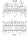
Fig. 2A , thecryogenic cooling device 14 is capable of producing non-uniform cryogenic cooling profiles. An exemplary non-uniformcryogenic cooling profile 16 is shown inFig. 2A . The length of the arrow-headed dashed lines 26a through 26k represent the cooling intensity discharged from each of the respective nozzles 18a through 18k, with a longer line indicating greater cooling intensity and the arrow head indicating the direction of flow. In order to simplify this figure, only the left-most and right-most nozzles 18a and 18k and dashed lines 26a through 26k are labeled. Similar labeling simplification is repeated for other features of the invention having multiple duplicate features. InFig. 2A , thecryogenic cooling profile 16 has maximum cooling intensity at the center of thecryogenic cooling device 14. The cooling intensity decreases to a minimum at each end of thecryogenic cooling device 14. -
Cryogenic cooling devices 14 and 114 (Fig. 2B ) are very similar to the tube-in-tube cryogenic spray bar disclosed inU.S. Patent Application No. 11/846,116, filed August 28, 2007 cryogenic cooling device 14 by two cryogenic fluid supply lines L1 and L2. A throttling gas is supplied to the cryogenic cooling device by two throttling gas supply lines G1 and G2. An optional purge gas is supplied to the cryogenic cooling device by two purge gas supply lines P1 and P2. - In this embodiment, the supplied cryogenic fluid flows into an inner tube and then into a "contact zone" located between the inner tube and the outer tube, where it mixes with the throttling gas. The tube-in-tube structure is fully disclosed in
U.S. Patent Application No. 11/846,116 , and therefore is neither shown inFig. 2A nor discussed in detail herein. As explained in detail inU.S. Patent Application No. 11/846,116 , adjusting the pressure at which the throttling gas is supplied to thecryogenic cooling device 14 via each of the throttling gas supply lines G1 and G2 enables the cryogenic cooling profile to be adjusted and controlled and enables the generation of non-uniform cryogenic cooling profiles. - A
proportional valve 15a, 15b (i.e., adjustable over a range of positions between fully open and fully closed) is provided on each of the throttling gas supply lines G1 and G2, which enable the pressure at which the throttling gas is supplied to thecryogenic cooling device 14 to be regulated in each of the throttling gas supply lines G1 and G2. In this embodiment, asingle valve 13 is provided to control the flow of cryogenic fluid through the cryogenic fluid supply lines L1 and L2. Asingle valve 13 is used in this embodiment because it is unnecessary (and difficult) to independently adjust the respective flow rates in each of the cryogenic fluid supply lines L1 and L2. In other embodiments, a valve could be provided on each of the cryogenic fluid supply lines L1 and L2. - Proportional valves (including valves15a, 15b) are described in this application as being used to regulate the pressure at which throttling gas is supplied to a cryogenic cooling device (including device 14). It should be understood that, the proportional valves of the embodiments of the invention described herein, are adjusted by increasing or decreasing the size of the opening through which the throttling gas flows, which causes a corresponding increase or decrease, respectively, in the flow rate of throttling gas through the opening. Increasing the size of the opening also decreases the pressure drop across the proportional valve, and therefore, increases the pressure of the throttling gas downstream of the proportional valve. Conversely, decreasing the size of the opening increases the pressure drop across the proportional valve, and therefore, decreases the downstream pressure of the throttling gas. Therefore, in the embodiments of the invention described herein, adjusting a proportional valve regulates both the flow rate and the pressure at which the throttling gas is provided to the cryogenic cooling device.
- Because the extremely low temperatures associated with cryogens can cause icing conditions that adversely affect control valve adjustment,
valve 13 is normally opened at the start of rolling operations to provide a desired flow rate of cryogenic fluid and is not adjusted until rolling is terminated. It should be understood, however, that adjusting thevalve 13 during rolling operations is not considered outside the scope of the present invention. - The purge gas supply lines P1 and P2 provide a means for preventing the build-up of condensation and frost on the
cryogenic cooling device 14, as set forth in PCT International Application No.PCT/US08/74462 on August 27, 2008 , filed concurrently with this application, which is incorporated herein by reference as if fully set forth. Asingle valve 20 is provided to control the flow of purge gas through the purge gas supply lines P1 and P2. In the interest of brevity, other structural elements disclosed in the above-referenced PCT Application which support the condensation and frost prevention feature are not repeated herein. -
Fig. 3 shows a delivery and control system embodiment for use with thecryogenic cooling device 14. The cryogenic fluid is supplied to the cryogenic fluid supply lines L1 and L2 by atank 50, which may optionally include a pressure regulator 53. Similarly, the throttling gas is supplied to the throttling gas supply lines G1 and G2 by atank 51, which may optionally include avaporizer 54. Thetank 51 also supplies the purge gas to the purge gas supply lines P1 and P2. Alternatively, the cryogenic fluid, throttling gas and purge gas could be supplied by a single tank, which would preferably have a vaporizer and a phase separator. - In this embodiment, the cryogenic fluid is liquid nitrogen (LIN) and the throttling and purge gases are gaseous nitrogen (at ambient temperature). The LIN may be supplied to the cryogenic cooling device as a liquid or in mixed-phase. Obviously other cryogenic fluids, throttling gases and purge gases could be used. In order to avoid condensation of the throttling gas when it meets the cryogenic fluid, it is preferable that the boiling point of the throttling gas be no greater than the boiling point of the cryogenic fluid.
- A
controller 17 receives data from a group ofsensors 52a through 52c, each of which measure a parameter of the cold rolling process. Thesensors 52a through 52c each preferably measure a parameter of the cold rolling process which will affect the desiredcryogenic cooling profile 16 of thecryogenic cooling device 14. In accordance with the present invention, the desiredcryogenic cooling profile 16 is preferably a profile that improves uniformity of thestrip 5 and/or minimizes damage to thestrip 5 during the cold rolling process. The desiredcryogenic cooling profile 16 will depend upon many factors, including, but not limited to, the parameters measured by one or more of thesensors 52a through 52c. - There are many operating parameters of the cold rolling process which could affect the desired
cryogenic cooling profile 16. Many of these operating parameters relate to physical properties of thestrip 5. Examples include, but are not limited to: - 1. the overall temperature of the
strip 5; - 2. the overall temperature of the
rolls - 3. the temperature profile across the width of the strip 5 (i.e., the direction perpendicular to the direction 8 shown in
Fig. 1 ); - 4. the temperature profile across the width of the
rolls 2, 3 (i.e., the direction perpendicular to the direction 8 shown inFig. 1 ); - 5. the shape (thickness, crown, etc.) of the
strip 5; - 6. stress on the
strip 5; - 7. stress in the
rolls - 8. the velocity of the
strip 5 or therolls - 9. the width of the
strip 5; and - 10. the diameter of the rolls, 2, 3 at several points along the rotational axis of the
rolls - In this embodiment,
sensor 52a measures the velocity of thestrip 5,sensor 52b measures the temperature profile across the width of thestrip 5 and sensor 52c measures the width of thestrip 5. Different numbers of sensors could be provided in other embodiments and different combinations of parameters could be measured. - The
controller 17 is preferably programmed to determine a desiredcryogenic cooling profile 16 based on data received from thesensors 52a through 52c. For example, thecontroller 17 could be programmed to increase the overall intensity of the desired cryogenic cooling profile 16 (by further opening bothvalves 15a and 15b) if thesensor 52a detects an increase in the velocity of thestrip 5. As another example, thecontroller 17 could be programmed to generate acryogenic cooling profile 16 having a localized increase in intensity at the portion of thestrip 5 in which a higher temperature is measured by thesensor 52b (e.g., in the center of the strip 5). - Once a desired
cryogenic cooling profile 16 has been determined, thecontroller 17 makes any necessary adjustments to thevalves 15a and 15b to generate the desiredcryogenic cooling profile 16. As measurements from thesensors 52a through 52c change (i.e., to reflect a change in a measured parameter of the cold rolling process), the desiredcryogenic cooling profile 16 may change, in which case thecontroller 17 will make further adjustments to thevalves 15a and 15b to regulate the throttling gas pressure in the throttling gas supply lines G1 and G2 to generate the current desiredcryogenic cooling profile 16. Accordingly, the present invention provides that capability to quickly and automatically adjust thecryogenic cooling profile 16 to changing process conditions. - As discussed above in the Background section, at many stages of cold rolling processes, the physical characteristics of the strip (e.g., temperature, thickness, etc.) are not uniform across the width of the strip. Therefore, the capability of the present invention to produce non-uniform cryogenic cooling profiles, particularly when taken in combination with ability of the present invention to quickly adjust to changing process conditions, can be advantageously used on cold rolling processes to produce an improved shape in a rolled product.
- In this embodiment, the
controller 17 is also adapted to adjust thevalve 13 for the cryogenic fluid supply lines L1 and L2, as well as thevalve 20 for the purge gas supply lines P1 and P2.Controller 17 may adjustvalve 13 to increase the flow of purge gas if there is an overall increase in the intensity of thecryogenic cooling profile 16. In this embodiment and as explained above, thevalve 20 is preferably not adjusted during operation of the cold rolling process. - It should be noted that the delivery and control system shown in
Fig. 3 , including thecontroller 17 andsensors -
Fig. 2B shows a second embodiment of thecryogenic cooling device 114. Thecryogenic cooling device 114 is very similar to thecryogenic cooling device 14 shown inFig. 2A , the primary difference being that the discharge comprises anelongated slot 118 instead of a plurality of nozzles 18a through 18k. In addition, thecryogenic cooling profile 116 shown in this embodiment is slightly different. -
Fig. 4A shows a third embodiment of thecryogenic cooling device 314, which provides for "sectionalized" or "zoned" control of a plurality of discharge nozzles 318a through 318k. Each of the nozzles 318a through 318k includes an internal manifold 335a through 335k, respectively, which is where the throttling gas and cryogenic fluid meet and mix (performing the same function of the mixing zone in thecryogenic cooling devices 14 and 114). The plurality of discharge nozzles 318a through 318k are grouped into three zones. The first zone comprises the nozzles 318d through 318h, which are the nozzles in the center of thecryogenic cooling device 314. The second zone consists of thenozzles 318b, 318c, 318i and 318j, which are outboard of (i.e., on either side of or flank) the nozzles of the first zone. The third zone consists of nozzles 318a and 318k, which are outboard of the nozzles of the first and second zones. - The cryogenic fluid, throttling gas and purge gas are supplied to the nozzles of each of the zones using one supply line per zone. For example, nozzles 318a and 318k of the third zone are supplied with cryogenic fluid by a cryogenic supply line L1, with throttling gas by throttling gas supply line G1, and with purge gas by purge gas supply line P1. In this embodiment, an
adjustable valve valve - In order to simplify the connection to a supply tank a backend throttling
gas supply line 312 is provided, which splits into the throttling gas supply lines G1, G2 and G3 upstream from thevalves backend supply lines - Having multiple nozzles grouped in "zones," with each zone having an independently-adjustable throttling gas supply, provides additional flexibility in the operation of the
cryogenic cooling device 314. A larger cooling intensity difference between zones is possible in this embodiment than in thecryogenic cooling devices Figs. 2A and2B . In addition, in this embodiment, it is possible to have greater cooling intensity near the ends of the cryogenic cooling device 314 (i.e., the third zone) than in the center (i.e., the first zone). Finally, "zoned" or "sectionalized" nozzles also enables the nozzles in any one of the zones to be turned off by increasing the throttling gas pressure delivered to nozzles in that zone until little or no cryogenic fluid is being discharged, or by closing the valve on the associated cryogenic supply line. This enables thecryogenic cooling device 314 to operate more efficiently when a relatively narrow strip is being rolled in the cold rolling process, which could result in significant operating cost savings. For example, if the width of the strip being rolled was only as wide as the first zone (spanning from nozzles 318d through 318h), the nozzles of the second and third zones could be turned off. As noted above, sensor 52c is configured to detect the width of thestrip 5. Therefore, thecontroller 17 could be programmed to automatically turn zones on and off depending upon the detected width of thestrip 5. The sectionalized cooling capability of thecryogenic cooling device 314 would also enable quick operational transitions between strips of different widths. -
Fig. 4B shows a fourth embodiment of the cryogenic cooling device 414, which is very similar to the third embodiment of thecryogenic cooling device 314, but includes two zones instead of three zones. -
Fig. 5 shows a fifth embodiment of the cryogenic cooling device 614, which includes a throttling gas supply line having an adjustable valve and a cryogenic fluid supply line for each of a plurality of nozzles. In order to simplifyFig. 5 , only the leftmost throttling gas valve 615a and the rightmost throttling gas valve 615k are labeled. Similarly, only the leftmost and rightmost nozzles 618a, 618k are labeled, along with the leftmost and rightmost manifolds 635a, 635k associated with each nozzle. In addition, the throttling gas supply lines are shown as solid lines and the cryogenic fluid supply lines are shown using lines having a dash, double-dot pattern. Asingle valve 613 controls the flow of cryogenic fluid through all of the cryogenic fluid supply lines. - Due to the fact that each nozzle has its own throttling gas supply line and adjustable valve, the cryogenic cooling device 614 provides the greatest degree of flexibility in generating cryogenic cooling profiles. This flexibility comes at the cost, however, of increased weight, complexity and manufacturing cost. Therefore, use of the cryogenic cooling device 614 is likely to only be warranted in applications having desired cryogenic cooling profiles that cannot be generated using the any of the first through fourth embodiments of the cryogenic cooling device discussed above.
- As such, an invention has been disclosed in terms of preferred embodiments and alternate embodiments thereof, which fulfills each one of the objects of the present invention as set forth above and provides a method and apparatus for a non-linear cryogenic liquid spray profile across the width of a metallic product rolled in a cold roll mill stand. Of course, various changes, modifications, and alterations from the teachings of the present invention may be contemplated by those skilled in the art without departing from the intended scope thereof. It is intended that the present invention only be limited by the terms of the appended claims.
Claims (14)
- A methodlcornprising:determining a non-uniform cryogenic cooling profile (16) for a discharge of a cryogenic cooling device (14) that is part of an industrial process based on at least one operating parameter of the industrial process; andgenerating the non-uniform cryogenic cooling profile (16),
wherein the generating step comprises:supplying a cryogenic fluid to each of a plurality of nozzles(18)of the cryogenic cooling device (14) and supplying a throttling gas; andregulating a pressure of the throttling gas in a manner that generates the non-uniform cryogenic cooling profile (16), whereinthe throttling gas is supplied to the plurality of nozzles (18) of the cryogenic cooling device 14. - The method of claim 1, wherein the determining step comprises determining the non-uniform cryogenic cooling profile (16) for the discharge of the cryogenic cooling device (14) based on the at least one operating parameter of the industrial process for the purpose of improving uniformity of a product of the industrial process.
- The method of claim 1, wherein the generating step comprises generating the non-uniform cooling profile (16) by supplying a cryogenic fluid to the cryogenic cooling device (14) and regulating the pressure of each of at least one throttling gas supply line (G1, G2) to the cryogenic cooling device (14).
- The method of claim 3, wherein the generating step comprises generating the non-uniform cooling profile (16) by supplying a cryogenic fluid to the cryogenic cooling device (14) and regulating the pressure of each of at least one throttling gas supply line (G1, G2) to the cryogenic cooling device (14) using a controller (17) that is adapted to control an adjustable valve (15a, 15b), on each of the at least one throttling gas supply line (G1, G2).
- The method recited in claim 1, wherein the generating step comprises generating the non-uniform cooling profile (16) by supplying liquid or mixed-phase nitrogen to the cryogenic cooling device (14) and regulating the pressure of at least one gaseous nitrogen supply line to the cryogenic cooling device (14).
- The method recited in claim 1, wherein the generating step comprises supplying the throttling gas to each of two throttling gas supply lines (G1, G2) located on the cryogenic cooling device (14) at a pressure that generates the non-uniform cryogenic cooling profile (16), the discharge of the cryogenic cooling device (14) comprising an elongated slot (118).
- The method of claim 1, wherein the generating step comprises:supplying the throttling gas to each of first and second throttling gas supply lines (G1, G2) the first throttling gas supply line (G1) being in flow communication with a first group of nozzles (18) and the second throttling gas supply line (G2) being in flow communication with a second group of nozzles (18), the second group of nozzles (18) being located outboard of the first group of nozzles (18), andregulating a pressure of the throttling gas supplied to each of the first and second throttling gas supply lines (G1, G2).
- The method of claim 1, further comprising:adjusting the non-uniform cooling profile (16) in response to a change in the at least one operating parameter of the industrial process; andgenerating the adjusted non-uniform cooling profile (16), and optionally wherein generating the adjusted non-uniform cooling profile (16) comprises adjusting at least one throttling gas supply line (G1, G2) to the cryogenic cooling device without adjusting any of at least one cryogenic fluid supply line (L1, L2) to the cryogenic cooling device (14).
- The method recited in claim 1, wherein the determining step comprises determining the non-uniform cryogenic cooling profile (16) for the discharge of the cryogenic cooling device (14) based on at least one operating parameter of a cold rolling process, and wherein optionally the determining step comprises determining the non-uniform cryogenic cooling profile for the discharge of the cryogenic cooling device (14) based on at least one operating parameter of a cold rolling process, the at least one operating parameter including one or more selected from the group of temperature measurements from a strip (5) being rolled by the cold rolling process, temperature measurements from a roll (2, 3) that is part of the cold rolling process, shape measurements from the strip (5), stress measurements from the strip (5), and stress measurements from the roll (2, 3).
- The method of claim 1, further comprising positioning the discharge of the cryogenic cooling device (14) at an element of the industrial process, and wherein optionally the positioning step comprises positioning the discharge of the cryogenic cooling device at an element of the industrial process, the element being selected from the group of a roll (2, 3) that is part of the industrial process and a strip (5) being rolled by the industrial process.
- An apparatus for use in an industrial process, the apparatus comprising:a cryogenic cooling device (14) having at least one discharge opening, the cryogenic cooling device (14) being connected to at least one cryogenic fluid supply line (L1, L2) and at least one discharge opening, the cryogenic cooling device being configured so that flow of cryogenic fluid through each of the at least one discharge opening is a function of the pressure at which a throttling gas is supplied to each of the at least one throttling gas supply line (G1, G2),at least one valve (15) that regulates flow of the throttling gas through each of the at least one throttling gas supply line (G1, G2), anda controller (17) having at least one sensor (52) adapted to measure at least one operating parameter of the industrial process;wherein the controller (17) is programmed to adjust each of the at least one valve (15) to generate a desired cryogenic cooling profile (16) for the cryogenic cooling device (14) based on input from the at least one sensor (52), whereinthe at least one throttling gas supply line (G1, G2) is in flow communication with at least one discharge opening.
- The apparatus of claim 11, whereina) the at least one discharge opening comprises a plurality of nozzles (18), orb) wherein the at least one throttling gas supply line (G1, G2) comprises first and second throttling gas supply lines (G1, G2) and the at least one discharge opening comprises first and second groups of nozzles (18), the second group of nozzles (18), being located outboard of the first group of nozzles (18), the first throttling gas supply line (G1) being in flow communication with a first group of nozzles (18) and the second throttling gas supply line (G2) being in flow communication with a second group of nozzles (18), wherein optionally the first and second groups of nozzles (18) are arranged in a row, orc) wherein the at least one valve (15) comprises a first valve (15a) located on the first throttling gas supply line (G1) and a second valve (15b) located on the second throttling gas supply line (G2), ord) wherein the controller (17) is capable of generating a non-uniform cooling profile (16) for the cryogenic cooling device (14).
- The apparatus of claim 11, wherein the at least one operating parameter of the industrial process comprises one or more physical properties of a strip (5) being rolled by the industrial process and a roll (2, 3) that is part of the industrial process.
- The apparatus of claim 13, wherein the at least one operating parameter of the industrial process comprises one or more selected from the group of temperature measurements from the strip (5), temperature measurements from the roll (2, 3), shape measurements from the strip (5), stress measurements from the strip (5), and stress measurements from the roll (2, 3).
Applications Claiming Priority (2)
| Application Number | Priority Date | Filing Date | Title |
|---|---|---|---|
| US96847907P | 2007-08-28 | 2007-08-28 | |
| PCT/US2008/074482 WO2009032700A1 (en) | 2007-08-28 | 2008-08-27 | Method and apparatus for discharging a non-linear cryogen spray across the width of a mill stand |
Publications (3)
| Publication Number | Publication Date |
|---|---|
| EP2200762A1 EP2200762A1 (en) | 2010-06-30 |
| EP2200762A4 EP2200762A4 (en) | 2011-10-05 |
| EP2200762B1 true EP2200762B1 (en) | 2014-08-06 |
Family
ID=42712022
Family Applications (1)
| Application Number | Title | Priority Date | Filing Date |
|---|---|---|---|
| EP08798811.9A Not-in-force EP2200762B1 (en) | 2007-08-28 | 2008-08-27 | Method and apparatus for discharging a non-linear cryogen spray across the width of a mill stand |
Country Status (7)
| Country | Link |
|---|---|
| US (1) | US20110036555A1 (en) |
| EP (1) | EP2200762B1 (en) |
| CN (1) | CN101842171A (en) |
| BR (1) | BRPI0815931A2 (en) |
| CA (1) | CA2697889C (en) |
| MX (1) | MX2010002068A (en) |
| WO (1) | WO2009032700A1 (en) |
Families Citing this family (13)
| Publication number | Priority date | Publication date | Assignee | Title |
|---|---|---|---|---|
| DE102007053523A1 (en) * | 2007-05-30 | 2008-12-04 | Sms Demag Ag | Device for influencing temperature distribution over width of slab or strip, particularly in one or multiple hot strip mill, has cooling device, which is provided with nozzles for applying cooling agent on slab or strip |
| US8474273B2 (en) | 2009-10-29 | 2013-07-02 | Air Products And Chemicals, Inc. | Apparatus and method for providing a temperature-controlled gas |
| CN102059250B (en) * | 2010-11-09 | 2012-07-04 | 燕山大学 | Electro-plastic two-roll mill of low-temperature liquid nitrogen cooling medium |
| EP2465619A1 (en) * | 2010-12-16 | 2012-06-20 | Siemens VAI Metals Technologies GmbH | Method and device for applying a lubricant when milling a metallic milling product |
| GB2511512B (en) * | 2013-03-05 | 2015-06-10 | Siemens Plc | Cooling device & method |
| ES2649160T3 (en) | 2013-03-11 | 2018-01-10 | Novelis, Inc. | Improved flatness of a laminated tape |
| US9427788B2 (en) * | 2013-11-13 | 2016-08-30 | Primetals Technologies USA LLC | Cooling device for a rolling mill work roll |
| EP2881186A1 (en) * | 2013-12-09 | 2015-06-10 | Linde Aktiengesellschaft | Method and apparatus to isolate the cold in cryogenic equipment |
| CN104492818B (en) * | 2014-11-28 | 2016-09-21 | 中冶南方工程技术有限公司 | Roll subsection cooling device and method |
| CN105710131B (en) * | 2014-12-04 | 2018-03-27 | 上海梅山钢铁股份有限公司 | A kind of method that Roll during Hot Strip Rolling coolant outlet water is axially distributed |
| US11473729B2 (en) * | 2016-10-19 | 2022-10-18 | Chart Inc. | Multiple head dosing arm device, system and method |
| CN109277407A (en) * | 2018-11-10 | 2019-01-29 | 瓯锟科技温州有限公司 | A kind of sheet metal rolling mill practice and equipment based on liquid nitrogen |
| CN114669613B (en) * | 2022-04-19 | 2023-06-20 | 安徽工业大学 | Flexible roller contact type Bao Daizu cooling method |
Family Cites Families (30)
| Publication number | Priority date | Publication date | Assignee | Title |
|---|---|---|---|---|
| US2986891A (en) * | 1958-02-10 | 1961-06-06 | Little Inc A | Low-temperature vessels |
| NL267134A (en) * | 1960-07-15 | |||
| US3431745A (en) * | 1965-09-15 | 1969-03-11 | Integral Process Syst Inc | Liquid nitrogen flash freezing |
| US3395548A (en) * | 1966-11-07 | 1968-08-06 | Mcmullen John J | Vessel for transporting liquefied gas at about ambient pressure |
| US3523437A (en) * | 1967-12-07 | 1970-08-11 | United States Steel Corp | Method of cold reducing |
| US4011734A (en) * | 1975-05-08 | 1977-03-15 | Parker-Hannifin Corporation | Cryogenic pressure regulator |
| SU710705A1 (en) * | 1977-04-29 | 1980-01-25 | Ордена Ленина Институт Проблем Управления | Method of controlling the heat profile of rolling mill rolls |
| US4252844A (en) * | 1978-07-26 | 1981-02-24 | Union Carbide Corporation | Process for mixing liquid additives with solid materials under sonic velocity conditions |
| US4262511A (en) * | 1978-09-08 | 1981-04-21 | Reycan Research Limited | Process for automatically controlling the shape of sheet metal produced in a rolling mill |
| FR2531516A1 (en) * | 1982-08-03 | 1984-02-10 | Applied Thermodynamics Lng Ser | LOW TEMPERATURE LIQUEFIED GAS TANK COMPRISING A SECONDARY BARRIER AND METHOD OF DETECTING THE POSSIBLE LEAKAGE OF THE SECONDARY BARRIER |
| US4481800A (en) * | 1982-10-22 | 1984-11-13 | Kennecott Corporation | Cold rolling mill for metal strip |
| GB8326652D0 (en) * | 1983-10-05 | 1983-11-09 | Davy Mckee Sheffield | Rolling mill |
| DE3430034A1 (en) * | 1984-08-16 | 1986-02-27 | Mannesmann AG, 4000 Düsseldorf | PLANNING REGULATION ON ROLLING MILLS |
| US4749337A (en) * | 1987-08-20 | 1988-06-07 | American Sigma, Inc. | Reciprocating bladder pump, and methods of constructing and utilizing same |
| US4806150A (en) * | 1988-01-21 | 1989-02-21 | The United States Department Of Energy | Device and technique for in-process sampling and analysis of molten metals and other liquids presenting harsh sampling conditions |
| DE4024605A1 (en) * | 1990-08-02 | 1992-02-06 | Wsp Ingenieurgesellschaft Fuer | DEVICE FOR COOLING EXTRUSION PROFILES |
| US5335503A (en) * | 1992-06-10 | 1994-08-09 | The Boc Group, Inc. | Cooling method and apparatus |
| US5344478A (en) * | 1993-08-02 | 1994-09-06 | Air Products And Chemicals, Inc. | Vortex dispersing nozzle for liquefied cryogenic inert gases used in blanketing of molten metals exposed to ambient air and method |
| US5730806A (en) * | 1993-08-30 | 1998-03-24 | The United States Of America As Represented By The Administrator Of The National Aeronautics & Space Administration | Gas-liquid supersonic cleaning and cleaning verification spray system |
| US5755128A (en) * | 1995-08-31 | 1998-05-26 | Tippins Incorporated | Method and apparatus for isothermally rolling strip product |
| DE59608495D1 (en) * | 1995-11-20 | 2002-01-31 | Sms Demag Ag | Device for influencing the profile of rolled rolled strip |
| FR2766738B1 (en) * | 1997-08-01 | 1999-09-03 | Air Liquide | METHOD AND DEVICE FOR SEQUENTIALLY SPRAYING A CRYOGENIC LIQUID, METHOD AND INSTALLATION FOR COOLING THEREOF |
| DE19953230C2 (en) | 1999-11-04 | 2003-08-28 | C D Waelzholz Produktionsgmbh | Cold rolling process |
| DE10129565C5 (en) * | 2001-06-20 | 2007-12-27 | Siemens Ag | Cooling method for a hot-rolled rolling stock and corresponding cooling line model |
| US7275720B2 (en) * | 2003-06-09 | 2007-10-02 | The Boeing Company | Actively cooled ceramic thermal protection system |
| US7054764B2 (en) * | 2003-09-29 | 2006-05-30 | Air Products And Chemicals, Inc. | Flow monitoring using flow control device |
| US7575639B2 (en) * | 2004-08-03 | 2009-08-18 | Spraying Systems Co. | Apparatus and method for processing sheet materials |
| DE102005001806A1 (en) | 2005-01-13 | 2006-07-20 | Air Liquide Deutschland Gmbh | Method for cold rolling of metallic rolling stock |
| US8715772B2 (en) * | 2005-04-12 | 2014-05-06 | Air Products And Chemicals, Inc. | Thermal deposition coating method |
| DE102005029461B3 (en) * | 2005-06-24 | 2006-12-07 | Siemens Ag | Applying coolant to rolled stock and/or to working rolls in a roll stand comprises applying the coolant in an amount depending on the work done in the gap between the rolls |
-
2008
- 2008-08-27 EP EP08798811.9A patent/EP2200762B1/en not_active Not-in-force
- 2008-08-27 CN CN200880113525A patent/CN101842171A/en active Pending
- 2008-08-27 US US12/675,274 patent/US20110036555A1/en not_active Abandoned
- 2008-08-27 MX MX2010002068A patent/MX2010002068A/en not_active Application Discontinuation
- 2008-08-27 CA CA2697889A patent/CA2697889C/en not_active Expired - Fee Related
- 2008-08-27 WO PCT/US2008/074482 patent/WO2009032700A1/en active Application Filing
- 2008-08-27 BR BRPI0815931A patent/BRPI0815931A2/en not_active IP Right Cessation
Also Published As
| Publication number | Publication date |
|---|---|
| CA2697889C (en) | 2012-10-02 |
| MX2010002068A (en) | 2010-03-18 |
| CN101842171A (en) | 2010-09-22 |
| US20110036555A1 (en) | 2011-02-17 |
| WO2009032700A1 (en) | 2009-03-12 |
| CA2697889A1 (en) | 2009-03-12 |
| EP2200762A4 (en) | 2011-10-05 |
| BRPI0815931A2 (en) | 2018-01-09 |
| EP2200762A1 (en) | 2010-06-30 |
Similar Documents
| Publication | Publication Date | Title |
|---|---|---|
| EP2200762B1 (en) | Method and apparatus for discharging a non-linear cryogen spray across the width of a mill stand | |
| KR101120665B1 (en) | Rolling apparatus and method of controlling shape of rolled sheet | |
| EP2505277B1 (en) | Hot-rolled steel sheet manufacturing device, and hot-rolled steel sheet manufacturing method | |
| US9180504B2 (en) | Device for influencing the temperature distribution over a width | |
| US8444909B2 (en) | Hot-strip cooling device | |
| US6314776B1 (en) | Sixth order actuator and mill set-up system for rolling mill profile and flatness control | |
| WO2017156122A1 (en) | Method and apparatus for controlling metal strip profile during rolling with direct measurement of process parameters | |
| US4899547A (en) | Hot strip mill cooling system | |
| JP4128816B2 (en) | Method and apparatus for shape control of cold rolling mill | |
| KR20200085880A (en) | Cooling device and cooling method of thick steel plate and manufacturing equipment and manufacturing method of thick steel plate | |
| US7137434B1 (en) | Continuous roll casting of ferrous and non-ferrous metals | |
| EP2964405A1 (en) | Cooling device&method | |
| JP2009274101A (en) | Control method and control device for roll coolant in foil rolling machine | |
| US5085066A (en) | Method for suppressing fluctation of width in hot rolled strip | |
| EP3825019B1 (en) | Cooling device for hot-rolled steel sheet and cooling method of hot-rolled steel sheet | |
| JP2898910B2 (en) | Coolant control method in plate rolling mill | |
| JP2979913B2 (en) | Metal strip cooling device | |
| JPH0671328A (en) | Controller for cooling hot rolled steel plate | |
| JP2979902B2 (en) | Metal strip cooling device | |
| JPH02112811A (en) | Shape control device for rolled sheet material | |
| JPH0681047A (en) | Device for cooling metal strip | |
| JPH09308903A (en) | Manufacture of hot rolled steel sheet |
Legal Events
| Date | Code | Title | Description |
|---|---|---|---|
| PUAI | Public reference made under article 153(3) epc to a published international application that has entered the european phase |
Free format text: ORIGINAL CODE: 0009012 |
|
| 17P | Request for examination filed |
Effective date: 20100325 |
|
| AK | Designated contracting states |
Kind code of ref document: A1 Designated state(s): AT BE BG CH CY CZ DE DK EE ES FI FR GB GR HR HU IE IS IT LI LT LU LV MC MT NL NO PL PT RO SE SI SK TR |
|
| AX | Request for extension of the european patent |
Extension state: AL BA MK RS |
|
| DAX | Request for extension of the european patent (deleted) | ||
| REG | Reference to a national code |
Ref country code: DE Ref legal event code: R079 Ref document number: 602008033737 Country of ref document: DE Free format text: PREVIOUS MAIN CLASS: B21B0027060000 Ipc: B21B0045020000 |
|
| A4 | Supplementary search report drawn up and despatched |
Effective date: 20110905 |
|
| RIC1 | Information provided on ipc code assigned before grant |
Ipc: B21B 27/10 20060101ALI20110829BHEP Ipc: B21B 37/74 20060101ALI20110829BHEP Ipc: B21B 45/02 20060101AFI20110829BHEP |
|
| 17Q | First examination report despatched |
Effective date: 20120924 |
|
| GRAP | Despatch of communication of intention to grant a patent |
Free format text: ORIGINAL CODE: EPIDOSNIGR1 |
|
| INTG | Intention to grant announced |
Effective date: 20140409 |
|
| GRAS | Grant fee paid |
Free format text: ORIGINAL CODE: EPIDOSNIGR3 |
|
| GRAA | (expected) grant |
Free format text: ORIGINAL CODE: 0009210 |
|
| AK | Designated contracting states |
Kind code of ref document: B1 Designated state(s): AT BE BG CH CY CZ DE DK EE ES FI FR GB GR HR HU IE IS IT LI LT LU LV MC MT NL NO PL PT RO SE SI SK TR |
|
| REG | Reference to a national code |
Ref country code: GB Ref legal event code: FG4D |
|
| REG | Reference to a national code |
Ref country code: AT Ref legal event code: REF Ref document number: 680760 Country of ref document: AT Kind code of ref document: T Effective date: 20140815 Ref country code: CH Ref legal event code: EP |
|
| REG | Reference to a national code |
Ref country code: IE Ref legal event code: FG4D |
|
| REG | Reference to a national code |
Ref country code: DE Ref legal event code: R096 Ref document number: 602008033737 Country of ref document: DE Effective date: 20140918 |
|
| PGFP | Annual fee paid to national office [announced via postgrant information from national office to epo] |
Ref country code: DE Payment date: 20140729 Year of fee payment: 7 |
|
| REG | Reference to a national code |
Ref country code: AT Ref legal event code: MK05 Ref document number: 680760 Country of ref document: AT Kind code of ref document: T Effective date: 20140806 |
|
| REG | Reference to a national code |
Ref country code: NL Ref legal event code: VDEP Effective date: 20140806 |
|
| REG | Reference to a national code |
Ref country code: LT Ref legal event code: MG4D |
|
| PG25 | Lapsed in a contracting state [announced via postgrant information from national office to epo] |
Ref country code: NO Free format text: LAPSE BECAUSE OF FAILURE TO SUBMIT A TRANSLATION OF THE DESCRIPTION OR TO PAY THE FEE WITHIN THE PRESCRIBED TIME-LIMIT Effective date: 20141106 Ref country code: GR Free format text: LAPSE BECAUSE OF FAILURE TO SUBMIT A TRANSLATION OF THE DESCRIPTION OR TO PAY THE FEE WITHIN THE PRESCRIBED TIME-LIMIT Effective date: 20141107 Ref country code: PT Free format text: LAPSE BECAUSE OF FAILURE TO SUBMIT A TRANSLATION OF THE DESCRIPTION OR TO PAY THE FEE WITHIN THE PRESCRIBED TIME-LIMIT Effective date: 20141209 Ref country code: ES Free format text: LAPSE BECAUSE OF FAILURE TO SUBMIT A TRANSLATION OF THE DESCRIPTION OR TO PAY THE FEE WITHIN THE PRESCRIBED TIME-LIMIT Effective date: 20140806 Ref country code: FI Free format text: LAPSE BECAUSE OF FAILURE TO SUBMIT A TRANSLATION OF THE DESCRIPTION OR TO PAY THE FEE WITHIN THE PRESCRIBED TIME-LIMIT Effective date: 20140806 Ref country code: SE Free format text: LAPSE BECAUSE OF FAILURE TO SUBMIT A TRANSLATION OF THE DESCRIPTION OR TO PAY THE FEE WITHIN THE PRESCRIBED TIME-LIMIT Effective date: 20140806 Ref country code: BG Free format text: LAPSE BECAUSE OF FAILURE TO SUBMIT A TRANSLATION OF THE DESCRIPTION OR TO PAY THE FEE WITHIN THE PRESCRIBED TIME-LIMIT Effective date: 20141106 Ref country code: LT Free format text: LAPSE BECAUSE OF FAILURE TO SUBMIT A TRANSLATION OF THE DESCRIPTION OR TO PAY THE FEE WITHIN THE PRESCRIBED TIME-LIMIT Effective date: 20140806 |
|
| PG25 | Lapsed in a contracting state [announced via postgrant information from national office to epo] |
Ref country code: PL Free format text: LAPSE BECAUSE OF FAILURE TO SUBMIT A TRANSLATION OF THE DESCRIPTION OR TO PAY THE FEE WITHIN THE PRESCRIBED TIME-LIMIT Effective date: 20140806 Ref country code: IS Free format text: LAPSE BECAUSE OF FAILURE TO SUBMIT A TRANSLATION OF THE DESCRIPTION OR TO PAY THE FEE WITHIN THE PRESCRIBED TIME-LIMIT Effective date: 20141206 Ref country code: CY Free format text: LAPSE BECAUSE OF FAILURE TO SUBMIT A TRANSLATION OF THE DESCRIPTION OR TO PAY THE FEE WITHIN THE PRESCRIBED TIME-LIMIT Effective date: 20140806 Ref country code: HR Free format text: LAPSE BECAUSE OF FAILURE TO SUBMIT A TRANSLATION OF THE DESCRIPTION OR TO PAY THE FEE WITHIN THE PRESCRIBED TIME-LIMIT Effective date: 20140806 Ref country code: AT Free format text: LAPSE BECAUSE OF FAILURE TO SUBMIT A TRANSLATION OF THE DESCRIPTION OR TO PAY THE FEE WITHIN THE PRESCRIBED TIME-LIMIT Effective date: 20140806 Ref country code: LV Free format text: LAPSE BECAUSE OF FAILURE TO SUBMIT A TRANSLATION OF THE DESCRIPTION OR TO PAY THE FEE WITHIN THE PRESCRIBED TIME-LIMIT Effective date: 20140806 Ref country code: NL Free format text: LAPSE BECAUSE OF FAILURE TO SUBMIT A TRANSLATION OF THE DESCRIPTION OR TO PAY THE FEE WITHIN THE PRESCRIBED TIME-LIMIT Effective date: 20140806 |
|
| REG | Reference to a national code |
Ref country code: CH Ref legal event code: PL |
|
| PG25 | Lapsed in a contracting state [announced via postgrant information from national office to epo] |
Ref country code: CZ Free format text: LAPSE BECAUSE OF FAILURE TO SUBMIT A TRANSLATION OF THE DESCRIPTION OR TO PAY THE FEE WITHIN THE PRESCRIBED TIME-LIMIT Effective date: 20140806 Ref country code: EE Free format text: LAPSE BECAUSE OF FAILURE TO SUBMIT A TRANSLATION OF THE DESCRIPTION OR TO PAY THE FEE WITHIN THE PRESCRIBED TIME-LIMIT Effective date: 20140806 Ref country code: RO Free format text: LAPSE BECAUSE OF FAILURE TO SUBMIT A TRANSLATION OF THE DESCRIPTION OR TO PAY THE FEE WITHIN THE PRESCRIBED TIME-LIMIT Effective date: 20140806 Ref country code: IT Free format text: LAPSE BECAUSE OF FAILURE TO SUBMIT A TRANSLATION OF THE DESCRIPTION OR TO PAY THE FEE WITHIN THE PRESCRIBED TIME-LIMIT Effective date: 20140806 Ref country code: DK Free format text: LAPSE BECAUSE OF FAILURE TO SUBMIT A TRANSLATION OF THE DESCRIPTION OR TO PAY THE FEE WITHIN THE PRESCRIBED TIME-LIMIT Effective date: 20140806 Ref country code: CH Free format text: LAPSE BECAUSE OF NON-PAYMENT OF DUE FEES Effective date: 20140831 Ref country code: LI Free format text: LAPSE BECAUSE OF NON-PAYMENT OF DUE FEES Effective date: 20140831 Ref country code: SK Free format text: LAPSE BECAUSE OF FAILURE TO SUBMIT A TRANSLATION OF THE DESCRIPTION OR TO PAY THE FEE WITHIN THE PRESCRIBED TIME-LIMIT Effective date: 20140806 Ref country code: BE Free format text: LAPSE BECAUSE OF NON-PAYMENT OF DUE FEES Effective date: 20140831 |
|
| REG | Reference to a national code |
Ref country code: DE Ref legal event code: R097 Ref document number: 602008033737 Country of ref document: DE |
|
| REG | Reference to a national code |
Ref country code: IE Ref legal event code: MM4A |
|
| PG25 | Lapsed in a contracting state [announced via postgrant information from national office to epo] |
Ref country code: MC Free format text: LAPSE BECAUSE OF FAILURE TO SUBMIT A TRANSLATION OF THE DESCRIPTION OR TO PAY THE FEE WITHIN THE PRESCRIBED TIME-LIMIT Effective date: 20140806 |
|
| PLBE | No opposition filed within time limit |
Free format text: ORIGINAL CODE: 0009261 |
|
| STAA | Information on the status of an ep patent application or granted ep patent |
Free format text: STATUS: NO OPPOSITION FILED WITHIN TIME LIMIT |
|
| 26N | No opposition filed |
Effective date: 20150507 |
|
| REG | Reference to a national code |
Ref country code: FR Ref legal event code: ST Effective date: 20150612 |
|
| GBPC | Gb: european patent ceased through non-payment of renewal fee |
Effective date: 20141106 |
|
| PG25 | Lapsed in a contracting state [announced via postgrant information from national office to epo] |
Ref country code: FR Free format text: LAPSE BECAUSE OF NON-PAYMENT OF DUE FEES Effective date: 20141006 Ref country code: IE Free format text: LAPSE BECAUSE OF NON-PAYMENT OF DUE FEES Effective date: 20140827 |
|
| PG25 | Lapsed in a contracting state [announced via postgrant information from national office to epo] |
Ref country code: GB Free format text: LAPSE BECAUSE OF NON-PAYMENT OF DUE FEES Effective date: 20141106 |
|
| PG25 | Lapsed in a contracting state [announced via postgrant information from national office to epo] |
Ref country code: SI Free format text: LAPSE BECAUSE OF FAILURE TO SUBMIT A TRANSLATION OF THE DESCRIPTION OR TO PAY THE FEE WITHIN THE PRESCRIBED TIME-LIMIT Effective date: 20140806 |
|
| REG | Reference to a national code |
Ref country code: DE Ref legal event code: R119 Ref document number: 602008033737 Country of ref document: DE |
|
| PG25 | Lapsed in a contracting state [announced via postgrant information from national office to epo] |
Ref country code: MT Free format text: LAPSE BECAUSE OF FAILURE TO SUBMIT A TRANSLATION OF THE DESCRIPTION OR TO PAY THE FEE WITHIN THE PRESCRIBED TIME-LIMIT Effective date: 20140806 |
|
| PG25 | Lapsed in a contracting state [announced via postgrant information from national office to epo] |
Ref country code: DE Free format text: LAPSE BECAUSE OF NON-PAYMENT OF DUE FEES Effective date: 20160301 Ref country code: LU Free format text: LAPSE BECAUSE OF NON-PAYMENT OF DUE FEES Effective date: 20140827 Ref country code: TR Free format text: LAPSE BECAUSE OF FAILURE TO SUBMIT A TRANSLATION OF THE DESCRIPTION OR TO PAY THE FEE WITHIN THE PRESCRIBED TIME-LIMIT Effective date: 20140806 Ref country code: HU Free format text: LAPSE BECAUSE OF FAILURE TO SUBMIT A TRANSLATION OF THE DESCRIPTION OR TO PAY THE FEE WITHIN THE PRESCRIBED TIME-LIMIT; INVALID AB INITIO Effective date: 20080827 Ref country code: BE Free format text: LAPSE BECAUSE OF FAILURE TO SUBMIT A TRANSLATION OF THE DESCRIPTION OR TO PAY THE FEE WITHIN THE PRESCRIBED TIME-LIMIT Effective date: 20140806 |