EP2200695B1 - Implant magnet insertion and removal tools - Google Patents
Implant magnet insertion and removal tools Download PDFInfo
- Publication number
- EP2200695B1 EP2200695B1 EP08837127.3A EP08837127A EP2200695B1 EP 2200695 B1 EP2200695 B1 EP 2200695B1 EP 08837127 A EP08837127 A EP 08837127A EP 2200695 B1 EP2200695 B1 EP 2200695B1
- Authority
- EP
- European Patent Office
- Prior art keywords
- magnet
- implant
- implantable device
- cradle
- positioning tool
- Prior art date
- Legal status (The legal status is an assumption and is not a legal conclusion. Google has not performed a legal analysis and makes no representation as to the accuracy of the status listed.)
- Active
Links
Images



Classifications
-
- A—HUMAN NECESSITIES
- A61—MEDICAL OR VETERINARY SCIENCE; HYGIENE
- A61N—ELECTROTHERAPY; MAGNETOTHERAPY; RADIATION THERAPY; ULTRASOUND THERAPY
- A61N1/00—Electrotherapy; Circuits therefor
- A61N1/18—Applying electric currents by contact electrodes
- A61N1/32—Applying electric currents by contact electrodes alternating or intermittent currents
- A61N1/36—Applying electric currents by contact electrodes alternating or intermittent currents for stimulation
- A61N1/372—Arrangements in connection with the implantation of stimulators
-
- A—HUMAN NECESSITIES
- A61—MEDICAL OR VETERINARY SCIENCE; HYGIENE
- A61F—FILTERS IMPLANTABLE INTO BLOOD VESSELS; PROSTHESES; DEVICES PROVIDING PATENCY TO, OR PREVENTING COLLAPSING OF, TUBULAR STRUCTURES OF THE BODY, e.g. STENTS; ORTHOPAEDIC, NURSING OR CONTRACEPTIVE DEVICES; FOMENTATION; TREATMENT OR PROTECTION OF EYES OR EARS; BANDAGES, DRESSINGS OR ABSORBENT PADS; FIRST-AID KITS
- A61F11/00—Methods or devices for treatment of the ears or hearing sense; Non-electric hearing aids; Methods or devices for enabling ear patients to achieve auditory perception through physiological senses other than hearing sense; Protective devices for the ears, carried on the body or in the hand
- A61F11/04—Methods or devices for enabling ear patients to achieve auditory perception through physiological senses other than hearing sense, e.g. through the touch sense
-
- A—HUMAN NECESSITIES
- A61—MEDICAL OR VETERINARY SCIENCE; HYGIENE
- A61B—DIAGNOSIS; SURGERY; IDENTIFICATION
- A61B17/00—Surgical instruments, devices or methods
- A61B17/30—Surgical pincettes, i.e. surgical tweezers without pivotal connections
-
- A—HUMAN NECESSITIES
- A61—MEDICAL OR VETERINARY SCIENCE; HYGIENE
- A61N—ELECTROTHERAPY; MAGNETOTHERAPY; RADIATION THERAPY; ULTRASOUND THERAPY
- A61N1/00—Electrotherapy; Circuits therefor
- A61N1/18—Applying electric currents by contact electrodes
- A61N1/32—Applying electric currents by contact electrodes alternating or intermittent currents
- A61N1/36—Applying electric currents by contact electrodes alternating or intermittent currents for stimulation
- A61N1/36036—Applying electric currents by contact electrodes alternating or intermittent currents for stimulation of the outer, middle or inner ear
- A61N1/36038—Cochlear stimulation
-
- A—HUMAN NECESSITIES
- A61—MEDICAL OR VETERINARY SCIENCE; HYGIENE
- A61N—ELECTROTHERAPY; MAGNETOTHERAPY; RADIATION THERAPY; ULTRASOUND THERAPY
- A61N1/00—Electrotherapy; Circuits therefor
- A61N1/18—Applying electric currents by contact electrodes
- A61N1/32—Applying electric currents by contact electrodes alternating or intermittent currents
- A61N1/36—Applying electric currents by contact electrodes alternating or intermittent currents for stimulation
- A61N1/372—Arrangements in connection with the implantation of stimulators
- A61N1/375—Constructional arrangements, e.g. casings
Definitions
- the present invention relates to implantable medical devices, and specifically to tools and techniques for inserting and removing magnets associated with such devices.
- Some implantable medical devices may include subcutaneous magnets which are used to hold in place various external elements such as transmission coils. But such magnets are not compatible with various medical imaging systems, for example, high field magnetic resonance imaging (MRI).
- MRI magnetic resonance imaging
- the magnet may be a small slippery sphere which the surgeon may have some difficulty grasping and handling.
- a removable magnet is located in a silicone pocket which has an opening (a lip) at the lateral side of an implant coil, and magnet removal and replacement is accomplished by means of conventional tweezers.
- US 2005/004629 discloses a magnetic alignment system that can form part of a cochlear implant system.
- the magnetic alignment system prevents substantial movement of a magnet of an implanted component during an MRI procedure, or allows for easy removal of the magnet to facilitate the MRI procedure.
- US 2004/243177 discloses a clasping tool for controlling an elongate tubular member comprising a tip constructed to support and limit lateral movement of the tubular member relative to the tip, and to permit longitudinal movement of the tubular member relative to the tip and an opposing tip constructed to retain the tubular member between the tips when the tips are brought together. Tips may have a flat region, half-tube region, forked region, looped region, or V-shaped region for grasping, holding, supporting and releasing the elongated tubular member Each tip may have a similar region.
- US 4 437 362 discloses a tool for handling a magnetic article including a first member having a jaw which is movable toward and away a second member having a corresponding jaw.
- Embodiments of the present invention are directed to a magnet positioning tool for use with an implantable device which includes an implant magnet.
- the magnet positioning tool of the present invention is defined in claim 1.
- the dependent claims concern preferred embodiments.
- Embodiments of the present invention are directed to a magnet positioning tool for use with an implantable device.
- the magnet positioning tool holds the implant magnet when inserting it into or removing it from the implanted device.
- Such a tool limits the mechanical stress placed on the implanted device and allows the size of the incision to be kept relatively small.
- Appropriate design helps maintain the electrical properties (e.g. inductivity, resistance) and the mechanical integrity of various elements of the implanted device such as the coil assembly (e.g., an optimal fit between the coil assembly and the magnet or magnet housing). This also helps preserve the integrity of the hermetically sealed housings (e.g. magnet housing) in the implanted device.
- the tool also enables the use of faster surgical techniques.
- Figure 1A-B shows cross-section views of an embodiment of a magnet positioning tool 100 having a pair of opposing positioning surfaces 101 and 102 , and a magnet cradle 103 having a concave spherical section for mechanically engaging a corresponding convex spherical section portion of an implant magnet 104 .
- Fig. 1A shows the magnet positioning tool 100 in place around an implantable device 105 when it is ready to remove the implant magnet 104
- Fig. 1B shows the magnet positioning tool 100 after it has removed the implant magnet 104 from beneath the implantable device 105 .
- the positioning tool 100 has a slim efficient profile (thinner than a surgeon's finger) which enables the surgical incision used for magnet removal and reinsertion to be as small as possible.
- the magnet positioning tool 100 in Fig. 1A-B includes a magnetic button 108 on the bottom of the magnet cradle 103 for magnetically engaging the implant magnet 104.
- the magnetic positioning tool 100 also includes a magnet ejector projection 107 on the positioning surface 101 opposite to the magnet cradle 103 for displacing the implant magnet 104 from the implantable device 105 into the magnet cradle 103 .
- the magnetic positioning tool 100 includes a position engagement surface 106 for aligning the positioning tool 100 with the implantable device 105 when the magnet cradle 103 is in correct operating position adjacent to the position of the implant magnet 104 in the implantable device 105 (e.g., concentrically over an implant coil even when the implant (coil) and magnet are hidden underneath a skin flap).
- the magnetic positioning tool 100 also has a stopper mechanism 110 that prevents the opposing surfaces 101 and 102 from approaching each other beyond some insertion distance so that when the implant magnet 104 is inserted by the magnet positioning tool 100 , the implant magnet 104 is not displaced past the magnet position in the implantable device 105 .
- Figure 2A-B shows cross-sectional views and Figure 3 shows a top view of another magnetic positioning tool 200 .
- Fig. 2A shows the magnet positioning tool 200 when it is ready to insert a replacement magnet 104 from beneath the implantable device 105
- Fig. 2B shows the magnet positioning tool 200 after it has inserted the replacement implant magnet 104 into the implantable device 105 .
- the magnetic positioning tool 200 includes a flushing ring 201 that provides flushing fluid to cleanse the magnet position in the implantable device 105 (e.g., the contact surface between the coil part and the magnet housing), immediately before inserting the implant magnet 104.
- the magnet positioning tool 200 may also include a flushing channel 202 for providing the flushing fluid to the flushing ring 201 .
- the magnetic positioning tool 200 also has a protective layer 203 (e.g., such as Teflon ® ) covering some of the magnet positioning tool 200 to protect the magnet 104 from being damaged by the tool.
- a protective layer 203 e.g., such
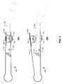
- Figure 4A-B shows cross-sectional views of another magnetic positioning tool 400 which engages the implant magnet 104 from above the implantable device 105 .
- Fig. 4A shows the magnet positioning tool 400 when it is ready to remove an implant magnet 104 from above the implantable device 105
- Fig. 4B shows the magnet positioning tool 400 after it has removed the implant magnet 104 .
- the magnet cradle 103 includes a magnet ejector projection 401 for displacing the implant magnet 104 from the implantable device 105 into a magnetic button 402 on the opposite side of the magnet positioning tool 400 that magnetically and mechanically engages the implant magnet 104 .
- the magnet positioning tool 400 also has a protective ring 403 for protecting the surface of the implantable device 105 from the magnet positioning tool 400 .
- Figure 5A-B shows cross-sectional views of another embodiment of a magnetic positioning tool 500 which engages the implant magnet 104 from above the implantable device 105 and which includes a flushing ring 501 that provides flushing fluid to cleanse the magnet position in the implantable device 105 , e.g., the contact surface between the coil part and the magnet housing, immediately before inserting the magnet 104 .
- the magnet positioning tool 500 also includes a flushing channel 502 for providing the flushing fluid to the flushing ring 501 .
- Lower protective ring 503 and upper protective ring 403 protect the surface of the implantable device 105 from the magnet positioning tool 500 .
Landscapes
- Health & Medical Sciences (AREA)
- Engineering & Computer Science (AREA)
- Biomedical Technology (AREA)
- Life Sciences & Earth Sciences (AREA)
- Public Health (AREA)
- Veterinary Medicine (AREA)
- Animal Behavior & Ethology (AREA)
- General Health & Medical Sciences (AREA)
- Neurology (AREA)
- Radiology & Medical Imaging (AREA)
- Nuclear Medicine, Radiotherapy & Molecular Imaging (AREA)
- Physiology (AREA)
- Physics & Mathematics (AREA)
- Acoustics & Sound (AREA)
- Biophysics (AREA)
- Otolaryngology (AREA)
- Psychology (AREA)
- Heart & Thoracic Surgery (AREA)
- Vascular Medicine (AREA)
- Dental Prosthetics (AREA)
- Prostheses (AREA)
Description
- The present invention relates to implantable medical devices, and specifically to tools and techniques for inserting and removing magnets associated with such devices.
- Some implantable medical devices, such as cochlear implant systems, may include subcutaneous magnets which are used to hold in place various external elements such as transmission coils. But such magnets are not compatible with various medical imaging systems, for example, high field magnetic resonance imaging (MRI). To perform an MRI on a patient with an implanted magnet, pre-imaging surgery may be required first to remove the magnet, then the actual imaging may be performed, after which another post-imaging surgery is needed to replace the magnet. Besides the inconvenience of this, the actual removal and replacement of the magnet is not trivial. The magnet may be a small slippery sphere which the surgeon may have some difficulty grasping and handling. In one known design, a removable magnet is located in a silicone pocket which has an opening (a lip) at the lateral side of an implant coil, and magnet removal and replacement is accomplished by means of conventional tweezers.
-
US 2005/004629 discloses a magnetic alignment system that can form part of a cochlear implant system. The magnetic alignment system prevents substantial movement of a magnet of an implanted component during an MRI procedure, or allows for easy removal of the magnet to facilitate the MRI procedure. -
US 2004/243177 discloses a clasping tool for controlling an elongate tubular member comprising a tip constructed to support and limit lateral movement of the tubular member relative to the tip, and to permit longitudinal movement of the tubular member relative to the tip and an opposing tip constructed to retain the tubular member between the tips when the tips are brought together. Tips may have a flat region, half-tube region, forked region, looped region, or V-shaped region for grasping, holding, supporting and releasing the elongated tubular member Each tip may have a similar region. -
US 4 437 362 discloses a tool for handling a magnetic article including a first member having a jaw which is movable toward and away a second member having a corresponding jaw. - Embodiments of the present invention are directed to a magnet positioning tool for use with an implantable device which includes an implant magnet. The magnet positioning tool of the present invention is defined in claim 1. The dependent claims concern preferred embodiments.
-
-
Figure 1A-B shows cross-sectional views of a magnet removal tool according to one specific embodiment of the present invention. -
Figure 2A-B shows cross-sectional views of another magnet insertion tool according to an embodiment of the present invention. -
Figure 3 show a top view of a magnet positioning tool according to an embodiment as shown inFig. 2 . -
Figure 4A-B shows cross-sectional views of another magnet insertion tool according to an embodiment of the present invention. -
Figure 5A-B shows cross-sectional views of another magnet insertion tool according to an embodiment of the present invention. - Embodiments of the present invention are directed to a magnet positioning tool for use with an implantable device. The magnet positioning tool holds the implant magnet when inserting it into or removing it from the implanted device. Such a tool limits the mechanical stress placed on the implanted device and allows the size of the incision to be kept relatively small. Appropriate design helps maintain the electrical properties (e.g. inductivity, resistance) and the mechanical integrity of various elements of the implanted device such as the coil assembly (e.g., an optimal fit between the coil assembly and the magnet or magnet housing). This also helps preserve the integrity of the hermetically sealed housings (e.g. magnet housing) in the implanted device. The tool also enables the use of faster surgical techniques.
-
Figure 1A-B shows cross-section views of an embodiment of amagnet positioning tool 100 having a pair ofopposing positioning surfaces magnet cradle 103 having a concave spherical section for mechanically engaging a corresponding convex spherical section portion of animplant magnet 104.Fig. 1A shows themagnet positioning tool 100 in place around animplantable device 105 when it is ready to remove theimplant magnet 104, andFig. 1B shows themagnet positioning tool 100 after it has removed theimplant magnet 104 from beneath theimplantable device 105. Thepositioning tool 100 has a slim efficient profile (thinner than a surgeon's finger) which enables the surgical incision used for magnet removal and reinsertion to be as small as possible. - In some specific embodiments, all or part of the
magnet cradle 103 may also be magnetic so that it can engage theimplant magnet 104 both mechanically and magnetically. For that purpose, themagnet positioning tool 100 inFig. 1A-B includes amagnetic button 108 on the bottom of themagnet cradle 103 for magnetically engaging theimplant magnet 104. Themagnetic positioning tool 100 also includes amagnet ejector projection 107 on thepositioning surface 101 opposite to themagnet cradle 103 for displacing theimplant magnet 104 from theimplantable device 105 into themagnet cradle 103. - The
magnetic positioning tool 100 includes aposition engagement surface 106 for aligning thepositioning tool 100 with theimplantable device 105 when themagnet cradle 103 is in correct operating position adjacent to the position of theimplant magnet 104 in the implantable device 105 (e.g., concentrically over an implant coil even when the implant (coil) and magnet are hidden underneath a skin flap). Themagnetic positioning tool 100 also has astopper mechanism 110 that prevents theopposing surfaces implant magnet 104 is inserted by themagnet positioning tool 100, theimplant magnet 104 is not displaced past the magnet position in theimplantable device 105. -
Figure 2A-B shows cross-sectional views andFigure 3 shows a top view of anothermagnetic positioning tool 200.Fig. 2A shows themagnet positioning tool 200 when it is ready to insert areplacement magnet 104 from beneath theimplantable device 105, andFig. 2B shows themagnet positioning tool 200 after it has inserted thereplacement implant magnet 104 into theimplantable device 105. Themagnetic positioning tool 200 includes aflushing ring 201 that provides flushing fluid to cleanse the magnet position in the implantable device 105 (e.g., the contact surface between the coil part and the magnet housing), immediately before inserting theimplant magnet 104. Themagnet positioning tool 200 may also include a flushingchannel 202 for providing the flushing fluid to theflushing ring 201. Themagnetic positioning tool 200 also has a protective layer 203 (e.g., such as Teflon®) covering some of themagnet positioning tool 200 to protect themagnet 104 from being damaged by the tool. -
Figure 4A-B shows cross-sectional views of anothermagnetic positioning tool 400 which engages theimplant magnet 104 from above theimplantable device 105.Fig. 4A shows themagnet positioning tool 400 when it is ready to remove animplant magnet 104 from above theimplantable device 105, andFig. 4B shows themagnet positioning tool 400 after it has removed theimplant magnet 104. InFig. 4A-B , themagnet cradle 103 includes amagnet ejector projection 401 for displacing theimplant magnet 104 from theimplantable device 105 into amagnetic button 402 on the opposite side of themagnet positioning tool 400 that magnetically and mechanically engages theimplant magnet 104. Themagnet positioning tool 400 also has aprotective ring 403 for protecting the surface of theimplantable device 105 from themagnet positioning tool 400. -
Figure 5A-B shows cross-sectional views of another embodiment of amagnetic positioning tool 500 which engages theimplant magnet 104 from above theimplantable device 105 and which includes aflushing ring 501 that provides flushing fluid to cleanse the magnet position in theimplantable device 105, e.g., the contact surface between the coil part and the magnet housing, immediately before inserting themagnet 104. Themagnet positioning tool 500 also includes a flushingchannel 502 for providing the flushing fluid to the flushingring 501. Lowerprotective ring 503 and upperprotective ring 403 protect the surface of theimplantable device 105 from themagnet positioning tool 500. - Although various exemplary embodiments of the invention have been disclosed, it should be apparent to those skilled in the art that various changes and modifications can be made which will achieve some of the advantages of the invention without departing from the scope of the appended claims.
Claims (11)
- A magnet positioning tool (100, 200, 400, 500) for use with an implantable device (105), the tool comprising:a pair of opposing positioning surfaces (101, 102), at least one of the positioning surfaces (101, 102) having a magnet cradle (103) for mechanically engaging an implant magnet (104) in the implantable device (105); anda stopper mechanism (110) having a position engagement surface (106), the stopper mechanism projecting from one of the opposing positioning surfaces (101, 102) toward the other opposing positioning surface (101, 102) and configured to prevent the opposing surfaces (101, 102) from approaching each other beyond an insertion distance, the position engagement surface (106) configured to engage the implantable device (105) and to align the implantable device (105) relative to the magnet cradle (103).
- A magnet positioning tool according to claim 1, wherein the magnet cradle (103) engages the implant magnet (104) mechanically and magnetically.
- A magnet positioning tool according to claim 1, further comprising:a magnet ejector projection (107) on the positioning surface opposite to the magnet cradle (103), the magnet ejector projection (107) protruding from the positioning surface and configured to displace the implant magnet (104) from the implantable device into the magnet cradle (103) when the position engagement surface is engaged with the implantable device.
- A magnet positioning tool according to claim 1, further comprising:a flushing ring (201, 501) on the positioning surface opposite to the magnet cradle for providing flushing fluid to cleanse a magnet position in the implantable device (105) before inserting the implant magnet (104).
- A magnet positioning tool according to claim 34, further comprising:a flushing channel (202, 502) for providing the flushing fluid to the flushing ring (201, 501).
- A magnet positioning tool (100) according to claim 1, wherein the magnet cradle (103) includes a concave spherical section for mechanically engaging a corresponding convex spherical section portion of the implant magnet (104).
- A magnet positioning tool according to claim 1, further comprising:a protective layer (203) covering at least a portion of the tool (200) to protect the implant magnet (104) from being damaged by the tool.
- A magnet positioning tool according to claim 1, wherein the magnet cradle (103) is configured to mechanically engage the implant magnet (104) from beneath the implantable device (105).
- A magnet positioning tool according to claim 1, wherein the magnet cradle (103) is configured to mechanically engage the implant magnet (104) from above the implantable device (105).
- A magnet positioning tool according to claim 1, wherein the magnet cradle (103) includes a magnetic button (108) on its bottom surface configured to magnetically engage the implant magnet (104).
- A magnet positioning tool according to claim 1, wherein the positioning surface opposite to the magnet cradle (103) includes a magnetic button (402) configured to magnetically engage the implant magnet (104), and wherein the magnet cradle (103) further includes a magnet ejector projection (401) that protrudes from its bottom surface and is configured to displace the implant magnet (104) from the implantable device (105) to the magnetic button (402) when the position engagement surface (106) is engaged with the implantable device (105).
Applications Claiming Priority (2)
| Application Number | Priority Date | Filing Date | Title |
|---|---|---|---|
| US97943107P | 2007-10-12 | 2007-10-12 | |
| PCT/US2008/079270 WO2009048999A1 (en) | 2007-10-12 | 2008-10-09 | Implant magnet insertion and removal tools |
Publications (2)
| Publication Number | Publication Date |
|---|---|
| EP2200695A1 EP2200695A1 (en) | 2010-06-30 |
| EP2200695B1 true EP2200695B1 (en) | 2014-12-10 |
Family
ID=40213005
Family Applications (1)
| Application Number | Title | Priority Date | Filing Date |
|---|---|---|---|
| EP08837127.3A Active EP2200695B1 (en) | 2007-10-12 | 2008-10-09 | Implant magnet insertion and removal tools |
Country Status (5)
| Country | Link |
|---|---|
| US (1) | US8758394B2 (en) |
| EP (1) | EP2200695B1 (en) |
| AU (1) | AU2008310852B2 (en) |
| CA (1) | CA2702352C (en) |
| WO (1) | WO2009048999A1 (en) |
Families Citing this family (43)
| Publication number | Priority date | Publication date | Assignee | Title |
|---|---|---|---|---|
| AU2003901696A0 (en) | 2003-04-09 | 2003-05-01 | Cochlear Limited | Implant magnet system |
| SE531177C2 (en) | 2007-05-24 | 2009-01-13 | Cochlear Ltd | Distance for implants |
| EP2227293B1 (en) | 2007-11-26 | 2019-08-28 | Attractive Surgical, LLC | Magnaretractor system |
| WO2009089330A1 (en) * | 2008-01-08 | 2009-07-16 | Med-El Elektromedizinische Geraete Gmbh | Surgical tool for preparing a bone for a device with a convex element |
| CL2009000279A1 (en) | 2009-02-06 | 2009-08-14 | Biotech Innovations Ltda | Remote guidance and traction system for mini-invasive surgery, comprising: at least one surgical and removable endopinza with hooking means and a portion of ferro-magnaetic material, a cylindrical introduction guide, a detachment mechanism, and at least a means of remote traction with magnet. |
| WO2012163397A1 (en) | 2011-05-30 | 2012-12-06 | Advanced Bionics Ag | Template for implanting a housing of a hearing instrument |
| WO2013043176A1 (en) | 2011-09-22 | 2013-03-28 | Advanced Bionics Ag | Retention of a magnet in a cochlear implant |
| US9949677B2 (en) * | 2011-10-21 | 2018-04-24 | Incube Labs, Llc | Implantable oximetric measurement apparatus and method of use |
| ES2699655T3 (en) * | 2012-04-19 | 2019-02-12 | Removaid As | Tool to remove an implanted article under the skin |
| US8764769B1 (en) | 2013-03-12 | 2014-07-01 | Levita Magnetics International Corp. | Grasper with magnetically-controlled positioning |
| CN105188839B (en) * | 2013-03-13 | 2018-05-22 | 领先仿生公司 | Magnet mounting systems and methods for use with cochlear implants |
| WO2014159023A1 (en) | 2013-03-14 | 2014-10-02 | Levita Magnetics International Corp. | Magnetic control assemblies and systems therefor |
| DK2853287T3 (en) * | 2013-09-26 | 2018-01-15 | Oticon Medical As | IMPLANTABLE DEVICE WITH REMOVABLE MAGNET |
| WO2015112645A1 (en) | 2014-01-21 | 2015-07-30 | Levita Magnetics International Corp. | Laparoscopic graspers and systems therefor |
| WO2015195359A1 (en) * | 2014-06-16 | 2015-12-23 | Med-El Elektromedizinische Geraete Gmbh | Implant magnet insertion and removal tools |
| US10091594B2 (en) | 2014-07-29 | 2018-10-02 | Cochlear Limited | Bone conduction magnetic retention system |
| WO2016168380A1 (en) | 2015-04-13 | 2016-10-20 | Levita Magnetics International Corp. | Grasper with magnetically-controlled positioning |
| EP3967244B1 (en) | 2015-04-13 | 2025-12-31 | Levita Magnetics International Corp. | RETRACTOR DEVICES |
| EP3302689B1 (en) | 2015-05-28 | 2019-02-27 | Advanced Bionics AG | Cochlear implants having mri-compatible magnet apparatus |
| US10130807B2 (en) | 2015-06-12 | 2018-11-20 | Cochlear Limited | Magnet management MRI compatibility |
| US20160381473A1 (en) | 2015-06-26 | 2016-12-29 | Johan Gustafsson | Magnetic retention device |
| AU2016318802A1 (en) * | 2015-09-09 | 2018-03-22 | Med-El Elektromedizinische Geraete Gmbh | Fixation of a removable magnet or a similar element in an elastic implant material |
| US10917730B2 (en) | 2015-09-14 | 2021-02-09 | Cochlear Limited | Retention magnet system for medical device |
| EP3377172B1 (en) | 2015-11-20 | 2021-07-28 | Advanced Bionics AG | Cochlear implants and magnets for use with same |
| WO2017105510A1 (en) | 2015-12-18 | 2017-06-22 | Advanced Bionics Ag | Cochlear implants having mri-compatible magnet apparatus and associated methods |
| WO2017105511A1 (en) | 2015-12-18 | 2017-06-22 | Advanced Bionics Ag | Cochlear implants having mri-compatible magnet apparatus |
| EP3399902B1 (en) | 2016-01-08 | 2024-06-12 | Levita Magnetics International Corp. | One-operator surgical system |
| EP3436141B1 (en) * | 2016-03-29 | 2019-11-06 | Med-El Elektromedizinische Geraete GmbH | Cochlear implant with clippable magnet |
| US10576276B2 (en) | 2016-04-29 | 2020-03-03 | Cochlear Limited | Implanted magnet management in the face of external magnetic fields |
| US10646718B2 (en) | 2016-11-15 | 2020-05-12 | Advanced Bionics Ag | Cochlear implants and magnets for use with same |
| US10674287B2 (en) | 2016-11-23 | 2020-06-02 | Cochlear Limited | Magnet placement and antenna placement of an implant |
| US11595768B2 (en) | 2016-12-02 | 2023-02-28 | Cochlear Limited | Retention force increasing components |
| US11020137B2 (en) | 2017-03-20 | 2021-06-01 | Levita Magnetics International Corp. | Directable traction systems and methods |
| WO2018190813A1 (en) | 2017-04-11 | 2018-10-18 | Advanced Bionics Ag | Cochlear implants with retrofit magnets |
| WO2018199936A1 (en) | 2017-04-25 | 2018-11-01 | Advanced Bionics Ag | Cochlear implants having impact resistant mri-compatible magnet apparatus |
| US11287495B2 (en) | 2017-05-22 | 2022-03-29 | Advanced Bionics Ag | Methods and apparatus for use with cochlear implants having magnet apparatus with magnetic material particles |
| US10646712B2 (en) | 2017-09-13 | 2020-05-12 | Advanced Bionics Ag | Cochlear implants having MRI-compatible magnet apparatus |
| EP3700622B1 (en) | 2017-10-26 | 2022-10-19 | Advanced Bionics AG | Headpieces and implantable cochlear stimulation systems including the same |
| CN112118888B (en) | 2018-02-15 | 2024-10-22 | 领先仿生公司 | Head-mounted device and implantable cochlear stimulation system including the same |
| CN108969194B (en) * | 2018-08-09 | 2024-04-09 | 浙江诺尔康神经电子科技股份有限公司 | Magnet tool in artificial cochlea |
| US12420101B2 (en) | 2019-09-27 | 2025-09-23 | Cochlear Limited | Multipole magnet for medical implant system |
| CN115361995A (en) | 2020-03-31 | 2022-11-18 | 领先仿生公司 | Earphone and implantable cochlear stimulation system including the earphone |
| US12440668B2 (en) | 2021-10-12 | 2025-10-14 | Advanced Bionics Ag | Cochlear implants having MRI-compatible magnet apparatus and associated systems and methods |
Citations (1)
| Publication number | Priority date | Publication date | Assignee | Title |
|---|---|---|---|---|
| US4437362A (en) * | 1981-10-26 | 1984-03-20 | Western Electric Co., Inc. | Tools for handling magnetic articles |
Family Cites Families (10)
| Publication number | Priority date | Publication date | Assignee | Title |
|---|---|---|---|---|
| US5002561A (en) * | 1989-08-17 | 1991-03-26 | Fisher Frank E | Protective hand forceps |
| US5897507A (en) * | 1996-11-25 | 1999-04-27 | Symbiosis Corporation | Biopsy forceps instrument having irrigation and aspiration capabilities |
| US6308101B1 (en) * | 1998-07-31 | 2001-10-23 | Advanced Bionics Corporation | Fully implantable cochlear implant system |
| US7346397B2 (en) * | 2000-06-30 | 2008-03-18 | Cochlear Limited | Cochlear implant |
| DE10127506A1 (en) * | 2001-06-06 | 2003-01-09 | Wolf Gmbh Richard | pliers |
| WO2003077776A1 (en) * | 2002-03-15 | 2003-09-25 | Nmt Medical, Inc. | Coupling system useful in placement of implants |
| AUPS192202A0 (en) * | 2002-04-23 | 2002-05-30 | Cochlear Limited | Mri-compatible cochlear implant |
| AU2003901696A0 (en) * | 2003-04-09 | 2003-05-01 | Cochlear Limited | Implant magnet system |
| AU2003901869A0 (en) * | 2003-04-17 | 2003-05-08 | Cochlear Limited | Manual insertion tool for a cochlear implant |
| WO2008109800A1 (en) * | 2007-03-07 | 2008-09-12 | Med-El Elektromedizinische Geraete Gmbh | Implantable device with removable magnet |
-
2008
- 2008-10-09 EP EP08837127.3A patent/EP2200695B1/en active Active
- 2008-10-09 WO PCT/US2008/079270 patent/WO2009048999A1/en not_active Ceased
- 2008-10-09 US US12/248,114 patent/US8758394B2/en not_active Expired - Fee Related
- 2008-10-09 AU AU2008310852A patent/AU2008310852B2/en active Active
- 2008-10-09 CA CA2702352A patent/CA2702352C/en active Active
Patent Citations (1)
| Publication number | Priority date | Publication date | Assignee | Title |
|---|---|---|---|---|
| US4437362A (en) * | 1981-10-26 | 1984-03-20 | Western Electric Co., Inc. | Tools for handling magnetic articles |
Also Published As
| Publication number | Publication date |
|---|---|
| WO2009048999A1 (en) | 2009-04-16 |
| CA2702352C (en) | 2015-06-02 |
| US20090099403A1 (en) | 2009-04-16 |
| AU2008310852A1 (en) | 2009-04-16 |
| CA2702352A1 (en) | 2009-04-16 |
| EP2200695A1 (en) | 2010-06-30 |
| US8758394B2 (en) | 2014-06-24 |
| AU2008310852B2 (en) | 2011-08-04 |
Similar Documents
| Publication | Publication Date | Title |
|---|---|---|
| US8758394B2 (en) | Implant magnet insertion and removal tools | |
| EP3154630B1 (en) | Implant magnet insertion and removal tools | |
| EP2968954B1 (en) | Magnet installation systems for use with cochlear implants | |
| US10456131B2 (en) | Method and apparatus for loading and implanting a shape memory implant | |
| ES2610736T3 (en) | System to insert an intraocular lens | |
| EP3954431B1 (en) | Fixation of a removable magnet in an elastic implant material | |
| EP3620207B1 (en) | Cochlear implant with clippable magnet | |
| EP3190996A1 (en) | Needle positioning apparatus | |
| AU2024205517B2 (en) | Inserter for glenosphere | |
| CN114867428A (en) | Ear surgical automated instrument and apparatus for an electrode clamp to capture and hold a cochlear implant | |
| CN108969194B (en) | Magnet tool in artificial cochlea | |
| CN105169553B (en) | Electrode cable protection device | |
| US20150245946A1 (en) | Method of positioning an intraocular device | |
| KR101785802B1 (en) | A needle, a needle pipe and a device for fixing the needle to the needle pipe | |
| EP2967537B1 (en) | Apparatus facilitating the repositioning of implanted medical devices | |
| US20100173261A1 (en) | Receiving element for an implant | |
| WO2000057799A9 (en) | Blade insertion apparatus for keratomes | |
| WO2013042091A2 (en) | Cochlear electrode insertion tool |
Legal Events
| Date | Code | Title | Description |
|---|---|---|---|
| PUAI | Public reference made under article 153(3) epc to a published international application that has entered the european phase |
Free format text: ORIGINAL CODE: 0009012 |
|
| 17P | Request for examination filed |
Effective date: 20100408 |
|
| AK | Designated contracting states |
Kind code of ref document: A1 Designated state(s): AT BE BG CH CY CZ DE DK EE ES FI FR GB GR HR HU IE IS IT LI LT LU LV MC MT NL NO PL PT RO SE SI SK TR |
|
| AX | Request for extension of the european patent |
Extension state: AL BA MK RS |
|
| DAX | Request for extension of the european patent (deleted) | ||
| 17Q | First examination report despatched |
Effective date: 20140321 |
|
| GRAP | Despatch of communication of intention to grant a patent |
Free format text: ORIGINAL CODE: EPIDOSNIGR1 |
|
| INTG | Intention to grant announced |
Effective date: 20140704 |
|
| GRAS | Grant fee paid |
Free format text: ORIGINAL CODE: EPIDOSNIGR3 |
|
| GRAA | (expected) grant |
Free format text: ORIGINAL CODE: 0009210 |
|
| AK | Designated contracting states |
Kind code of ref document: B1 Designated state(s): AT BE BG CH CY CZ DE DK EE ES FI FR GB GR HR HU IE IS IT LI LT LU LV MC MT NL NO PL PT RO SE SI SK TR |
|
| REG | Reference to a national code |
Ref country code: GB Ref legal event code: FG4D |
|
| REG | Reference to a national code |
Ref country code: CH Ref legal event code: EP |
|
| REG | Reference to a national code |
Ref country code: IE Ref legal event code: FG4D |
|
| REG | Reference to a national code |
Ref country code: AT Ref legal event code: REF Ref document number: 700344 Country of ref document: AT Kind code of ref document: T Effective date: 20150115 |
|
| REG | Reference to a national code |
Ref country code: DE Ref legal event code: R096 Ref document number: 602008035812 Country of ref document: DE Effective date: 20150122 |
|
| REG | Reference to a national code |
Ref country code: CH Ref legal event code: NV Representative=s name: OFFICE ERNEST T. FREYLINGER S.A., CH |
|
| REG | Reference to a national code |
Ref country code: AT Ref legal event code: MK05 Ref document number: 700344 Country of ref document: AT Kind code of ref document: T Effective date: 20141210 Ref country code: NL Ref legal event code: VDEP Effective date: 20141210 |
|
| REG | Reference to a national code |
Ref country code: NL Ref legal event code: VDEP Effective date: 20141210 |
|
| PG25 | Lapsed in a contracting state [announced via postgrant information from national office to epo] |
Ref country code: NO Free format text: LAPSE BECAUSE OF FAILURE TO SUBMIT A TRANSLATION OF THE DESCRIPTION OR TO PAY THE FEE WITHIN THE PRESCRIBED TIME-LIMIT Effective date: 20150310 Ref country code: LT Free format text: LAPSE BECAUSE OF FAILURE TO SUBMIT A TRANSLATION OF THE DESCRIPTION OR TO PAY THE FEE WITHIN THE PRESCRIBED TIME-LIMIT Effective date: 20141210 Ref country code: FI Free format text: LAPSE BECAUSE OF FAILURE TO SUBMIT A TRANSLATION OF THE DESCRIPTION OR TO PAY THE FEE WITHIN THE PRESCRIBED TIME-LIMIT Effective date: 20141210 Ref country code: ES Free format text: LAPSE BECAUSE OF FAILURE TO SUBMIT A TRANSLATION OF THE DESCRIPTION OR TO PAY THE FEE WITHIN THE PRESCRIBED TIME-LIMIT Effective date: 20141210 |
|
| REG | Reference to a national code |
Ref country code: LT Ref legal event code: MG4D |
|
| PG25 | Lapsed in a contracting state [announced via postgrant information from national office to epo] |
Ref country code: GR Free format text: LAPSE BECAUSE OF FAILURE TO SUBMIT A TRANSLATION OF THE DESCRIPTION OR TO PAY THE FEE WITHIN THE PRESCRIBED TIME-LIMIT Effective date: 20150311 Ref country code: LV Free format text: LAPSE BECAUSE OF FAILURE TO SUBMIT A TRANSLATION OF THE DESCRIPTION OR TO PAY THE FEE WITHIN THE PRESCRIBED TIME-LIMIT Effective date: 20141210 Ref country code: AT Free format text: LAPSE BECAUSE OF FAILURE TO SUBMIT A TRANSLATION OF THE DESCRIPTION OR TO PAY THE FEE WITHIN THE PRESCRIBED TIME-LIMIT Effective date: 20141210 Ref country code: SE Free format text: LAPSE BECAUSE OF FAILURE TO SUBMIT A TRANSLATION OF THE DESCRIPTION OR TO PAY THE FEE WITHIN THE PRESCRIBED TIME-LIMIT Effective date: 20141210 Ref country code: HR Free format text: LAPSE BECAUSE OF FAILURE TO SUBMIT A TRANSLATION OF THE DESCRIPTION OR TO PAY THE FEE WITHIN THE PRESCRIBED TIME-LIMIT Effective date: 20141210 |
|
| PG25 | Lapsed in a contracting state [announced via postgrant information from national office to epo] |
Ref country code: NL Free format text: LAPSE BECAUSE OF FAILURE TO SUBMIT A TRANSLATION OF THE DESCRIPTION OR TO PAY THE FEE WITHIN THE PRESCRIBED TIME-LIMIT Effective date: 20141210 |
|
| PG25 | Lapsed in a contracting state [announced via postgrant information from national office to epo] |
Ref country code: CZ Free format text: LAPSE BECAUSE OF FAILURE TO SUBMIT A TRANSLATION OF THE DESCRIPTION OR TO PAY THE FEE WITHIN THE PRESCRIBED TIME-LIMIT Effective date: 20141210 Ref country code: RO Free format text: LAPSE BECAUSE OF FAILURE TO SUBMIT A TRANSLATION OF THE DESCRIPTION OR TO PAY THE FEE WITHIN THE PRESCRIBED TIME-LIMIT Effective date: 20141210 Ref country code: EE Free format text: LAPSE BECAUSE OF FAILURE TO SUBMIT A TRANSLATION OF THE DESCRIPTION OR TO PAY THE FEE WITHIN THE PRESCRIBED TIME-LIMIT Effective date: 20141210 Ref country code: PT Free format text: LAPSE BECAUSE OF FAILURE TO SUBMIT A TRANSLATION OF THE DESCRIPTION OR TO PAY THE FEE WITHIN THE PRESCRIBED TIME-LIMIT Effective date: 20150410 Ref country code: SK Free format text: LAPSE BECAUSE OF FAILURE TO SUBMIT A TRANSLATION OF THE DESCRIPTION OR TO PAY THE FEE WITHIN THE PRESCRIBED TIME-LIMIT Effective date: 20141210 |
|
| PG25 | Lapsed in a contracting state [announced via postgrant information from national office to epo] |
Ref country code: PL Free format text: LAPSE BECAUSE OF FAILURE TO SUBMIT A TRANSLATION OF THE DESCRIPTION OR TO PAY THE FEE WITHIN THE PRESCRIBED TIME-LIMIT Effective date: 20141210 Ref country code: IS Free format text: LAPSE BECAUSE OF FAILURE TO SUBMIT A TRANSLATION OF THE DESCRIPTION OR TO PAY THE FEE WITHIN THE PRESCRIBED TIME-LIMIT Effective date: 20150410 |
|
| REG | Reference to a national code |
Ref country code: DE Ref legal event code: R097 Ref document number: 602008035812 Country of ref document: DE |
|
| PLBE | No opposition filed within time limit |
Free format text: ORIGINAL CODE: 0009261 |
|
| STAA | Information on the status of an ep patent application or granted ep patent |
Free format text: STATUS: NO OPPOSITION FILED WITHIN TIME LIMIT |
|
| PG25 | Lapsed in a contracting state [announced via postgrant information from national office to epo] |
Ref country code: DK Free format text: LAPSE BECAUSE OF FAILURE TO SUBMIT A TRANSLATION OF THE DESCRIPTION OR TO PAY THE FEE WITHIN THE PRESCRIBED TIME-LIMIT Effective date: 20141210 |
|
| REG | Reference to a national code |
Ref country code: FR Ref legal event code: PLFP Year of fee payment: 8 |
|
| 26N | No opposition filed |
Effective date: 20150911 |
|
| PG25 | Lapsed in a contracting state [announced via postgrant information from national office to epo] |
Ref country code: IT Free format text: LAPSE BECAUSE OF FAILURE TO SUBMIT A TRANSLATION OF THE DESCRIPTION OR TO PAY THE FEE WITHIN THE PRESCRIBED TIME-LIMIT Effective date: 20141210 |
|
| PG25 | Lapsed in a contracting state [announced via postgrant information from national office to epo] |
Ref country code: SI Free format text: LAPSE BECAUSE OF FAILURE TO SUBMIT A TRANSLATION OF THE DESCRIPTION OR TO PAY THE FEE WITHIN THE PRESCRIBED TIME-LIMIT Effective date: 20141210 |
|
| PG25 | Lapsed in a contracting state [announced via postgrant information from national office to epo] |
Ref country code: BE Free format text: LAPSE BECAUSE OF FAILURE TO SUBMIT A TRANSLATION OF THE DESCRIPTION OR TO PAY THE FEE WITHIN THE PRESCRIBED TIME-LIMIT Effective date: 20141210 Ref country code: LU Free format text: LAPSE BECAUSE OF FAILURE TO SUBMIT A TRANSLATION OF THE DESCRIPTION OR TO PAY THE FEE WITHIN THE PRESCRIBED TIME-LIMIT Effective date: 20151009 |
|
| GBPC | Gb: european patent ceased through non-payment of renewal fee |
Effective date: 20151009 |
|
| PG25 | Lapsed in a contracting state [announced via postgrant information from national office to epo] |
Ref country code: MC Free format text: LAPSE BECAUSE OF FAILURE TO SUBMIT A TRANSLATION OF THE DESCRIPTION OR TO PAY THE FEE WITHIN THE PRESCRIBED TIME-LIMIT Effective date: 20141210 |
|
| REG | Reference to a national code |
Ref country code: IE Ref legal event code: MM4A |
|
| PG25 | Lapsed in a contracting state [announced via postgrant information from national office to epo] |
Ref country code: GB Free format text: LAPSE BECAUSE OF NON-PAYMENT OF DUE FEES Effective date: 20151009 |
|
| REG | Reference to a national code |
Ref country code: FR Ref legal event code: PLFP Year of fee payment: 9 |
|
| PG25 | Lapsed in a contracting state [announced via postgrant information from national office to epo] |
Ref country code: IE Free format text: LAPSE BECAUSE OF NON-PAYMENT OF DUE FEES Effective date: 20151009 |
|
| PG25 | Lapsed in a contracting state [announced via postgrant information from national office to epo] |
Ref country code: HU Free format text: LAPSE BECAUSE OF FAILURE TO SUBMIT A TRANSLATION OF THE DESCRIPTION OR TO PAY THE FEE WITHIN THE PRESCRIBED TIME-LIMIT; INVALID AB INITIO Effective date: 20081009 Ref country code: BG Free format text: LAPSE BECAUSE OF FAILURE TO SUBMIT A TRANSLATION OF THE DESCRIPTION OR TO PAY THE FEE WITHIN THE PRESCRIBED TIME-LIMIT Effective date: 20141210 |
|
| PG25 | Lapsed in a contracting state [announced via postgrant information from national office to epo] |
Ref country code: CY Free format text: LAPSE BECAUSE OF FAILURE TO SUBMIT A TRANSLATION OF THE DESCRIPTION OR TO PAY THE FEE WITHIN THE PRESCRIBED TIME-LIMIT Effective date: 20141210 |
|
| PG25 | Lapsed in a contracting state [announced via postgrant information from national office to epo] |
Ref country code: TR Free format text: LAPSE BECAUSE OF FAILURE TO SUBMIT A TRANSLATION OF THE DESCRIPTION OR TO PAY THE FEE WITHIN THE PRESCRIBED TIME-LIMIT Effective date: 20141210 Ref country code: MT Free format text: LAPSE BECAUSE OF FAILURE TO SUBMIT A TRANSLATION OF THE DESCRIPTION OR TO PAY THE FEE WITHIN THE PRESCRIBED TIME-LIMIT Effective date: 20141210 |
|
| REG | Reference to a national code |
Ref country code: FR Ref legal event code: PLFP Year of fee payment: 10 |
|
| REG | Reference to a national code |
Ref country code: FR Ref legal event code: PLFP Year of fee payment: 11 |
|
| REG | Reference to a national code |
Ref country code: CH Ref legal event code: U11 Free format text: ST27 STATUS EVENT CODE: U-0-0-U10-U11 (AS PROVIDED BY THE NATIONAL OFFICE) Effective date: 20251101 |
|
| PGFP | Annual fee paid to national office [announced via postgrant information from national office to epo] |
Ref country code: DE Payment date: 20251028 Year of fee payment: 18 |
|
| PGFP | Annual fee paid to national office [announced via postgrant information from national office to epo] |
Ref country code: FR Payment date: 20251027 Year of fee payment: 18 |
|
| PGFP | Annual fee paid to national office [announced via postgrant information from national office to epo] |
Ref country code: CH Payment date: 20251101 Year of fee payment: 18 |