EP2200274A2 - Main face choosing device, method for controlling same, and image capturing apparatus - Google Patents
Main face choosing device, method for controlling same, and image capturing apparatus Download PDFInfo
- Publication number
- EP2200274A2 EP2200274A2 EP09179311A EP09179311A EP2200274A2 EP 2200274 A2 EP2200274 A2 EP 2200274A2 EP 09179311 A EP09179311 A EP 09179311A EP 09179311 A EP09179311 A EP 09179311A EP 2200274 A2 EP2200274 A2 EP 2200274A2
- Authority
- EP
- European Patent Office
- Prior art keywords
- face
- main face
- faces
- detected
- main
- Prior art date
- Legal status (The legal status is an assumption and is not a legal conclusion. Google has not performed a legal analysis and makes no representation as to the accuracy of the status listed.)
- Granted
Links
Images


Classifications
-
- H—ELECTRICITY
- H04—ELECTRIC COMMUNICATION TECHNIQUE
- H04N—PICTORIAL COMMUNICATION, e.g. TELEVISION
- H04N23/00—Cameras or camera modules comprising electronic image sensors; Control thereof
- H04N23/60—Control of cameras or camera modules
- H04N23/61—Control of cameras or camera modules based on recognised objects
- H04N23/611—Control of cameras or camera modules based on recognised objects where the recognised objects include parts of the human body
-
- G—PHYSICS
- G06—COMPUTING OR CALCULATING; COUNTING
- G06T—IMAGE DATA PROCESSING OR GENERATION, IN GENERAL
- G06T7/00—Image analysis
- G06T7/10—Segmentation; Edge detection
- G06T7/11—Region-based segmentation
-
- G—PHYSICS
- G06—COMPUTING OR CALCULATING; COUNTING
- G06T—IMAGE DATA PROCESSING OR GENERATION, IN GENERAL
- G06T7/00—Image analysis
- G06T7/40—Analysis of texture
-
- G—PHYSICS
- G06—COMPUTING OR CALCULATING; COUNTING
- G06T—IMAGE DATA PROCESSING OR GENERATION, IN GENERAL
- G06T2207/00—Indexing scheme for image analysis or image enhancement
- G06T2207/30—Subject of image; Context of image processing
- G06T2207/30196—Human being; Person
- G06T2207/30201—Face
Definitions
- the present invention relates to a main face choosing device, a method for controlling the choosing device, and an image capturing apparatus.
- image capturing apparatuses e.g., digital still cameras and digital video cameras
- AF auto-focus
- AE auto-exposure
- AF and so on In order to more precisely perform AF, AE, and so on (hereinafter collectively referred to as "AF and so on") suited to the face of a human figure, some apparatuses have the function of detecting the face of a human figure in a captured image.
- some of the apparatuses have the function of choosing the face of the human figure determined to be a main subject (hereinafter referred to as the "main face") from among the faces of the human figures.
- the choice of the main face has been made based on the states of the faces of the human figures in the captured image.
- the wording "the states of the faces of the human figures" used herein refers to parameters representing, for example, the positions of the faces in the captured image and the sizes of the faces.
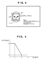
- FIG. 4 shows an example of information on the face of a human figure in a captured image.
- face information is sought for each face.
- Such face information includes the distance from the coordinates of the center of the captured image (center_x, center_y) to the coordinates of the center of the detected face (Face 1) (x1, y1).
- the information also includes a face size (size 1) representing the length of each side of the face assumed to be of a square shape and a reliability value representing a probability that the detected face will be the face of a human figure.
- the face size can be set such that the ratio of the flesh-colored area in the predetermined-size square stands at a predetermined value.
- the reliability is determined based on whether there are two eyes or not, the distance between the two eyes, whether or not there is a nose between the two eyes, and so on. In this case, it is assumed that the reliability is represented on a scale from 1 to 10, and a 1 indicates the highest probability of the face being of a human figure.
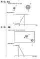
- a first weight is calculated through the use of the reliability of the detected face and a reliability-weight characteristic graph as shown in FIG. 5 .
- the x-axis indicates the input, that is, the reliability of the detected face
- the y-axis indicates the output, that is, the first weight.
- the first weight is set to 1.0 when the reliability stands between 1 to 3 inclusive; the point indicating the reliability 3 and the first weight of 1.0 and the point indicating the reliability 5 and the first weight of 0 are connected to each other with a straight line; and the first weight is set at 0 when the reliability stands at 5 or higher.
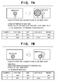
- a second weight is calculated through the use of the size of the detected face and a face size-weight characteristic graph in FIG. 6A .
- the x-axis indicates the input, that is, the size of the detected face
- the y-axis indicates the output, that is, the second weight.
- the point indicating a face size of 0 pixels and the second weight of 0 and the point indicating a face size of 20 pixels and the second weight of 0.2 are connected to each other with a straight line.
- the point indicating a face size of 20 pixels and the second weight of 0.2 and the point indicating a face size of 30 pixels and the second weight of 1 are connected to each other with a straight line, and the second weight is set to 1.0 when a face size is 30 pixels or more.
- the second weight when the size W1 of a face F1 is not more than 20 pixels, the second weight is a maximum of 0.2. However, when the size W2 of a face F2 is in the range of 20 to 30 pixels, the second weight varies from 0.2 to 1.0. That is, when the face size exceeds 20 pixels representing a face size worthy of being determined as a main face, the value of the second weight changes abruptly; therefore, the face F2 worthy of being the main face is given a higher weight value.
- distance information dist in the form of coordinate values on the distances between the center O of a captured image and the centers of detected faces F1 and F2 is extracted.
- third weights are calculated by using the extracted information dist and a distance-weight characteristic graph in FIG. 6B .
- the size of the captured image in which face detection is to be done is 320 ⁇ 240 pixels, and the weight is set at 1.0 when the distance from the center O is 10 pixels or fewer.
- the point indicating a distance of 10 pixels and a third weight of 1.0 and the point indicating a distance of 80 pixels and a third weight of 0 are connected to each other with a straight line, and the weight is set at 0 when the distance is 80 pixels or more.
- the weight when the distance from the center of the face F1 is of the order of 10 pixels, the weight is 1.0. However, when the distance from the center of the face F2 is not fewer than 10 pixels, the weight is below 1.0; when the distance from the center of the face F2 is 80 pixels or more, the weight is 0. That is, the face F1, which is close to the image's center and worthy of being determined as a main face, is given a large weight value.
- the face with the largest weight value can be determined to be the most likely main face in the frame.
- the coordinates of a face chosen as a main face at the time of the last face detection are read out, and then the distance between the coordinates read out and the coordinates of each newly detected face is determined by using, for example, Pythagorean theorem. Thereafter, the face nearest the last chosen main face is assigned a fourth weight of 1.4, and the other faces a fourth weight of 1.0.
- the final weight of each face is calculated by multiplying the fourth weight and the product of the first to third weights, following which the face with the greatest final weight is determined (chosen) to be a main face at that time. Therefore, even in the case where faces other than the main face are higher than the main face in the weighting product based on their reliability, size, and position, the possibility that they are chosen as a newly determined main face is small when they are away from the face chosen as the main face at the time of the last face detection. Thus limitations are placed on main face changeover and, hence, frequent main face changeovers can be suppressed.
- FIGS. 7A and 7B illustrate main face determination operations performed when a face A is detected after the detection of a main face B.
- a final weight value is determined by multiplying (or adding) three weight values found from the position and size of each face and the distance between the last main face and each face, and then the next main face is determined based on the product (or sum).
- the face A of a passerby has been included in the captured image at a position between the image capturing apparatus and the main face B as a main subject for example, the face A image becomes much larger than the face B image. Therefore, even if the fourth weight described above is taken into consideration, the face A will be assigned a larger final weight value than the face B, and then a main face changeover from the face B to the face A will be immediately effected at such a time.
- the final weight value assigned to the face A does not exceed that assigned to the face B at times due to small differences in their sizes and their positions in the frame.
- the main face B has sometimes remained chosen as the main subject; therefore, the face A the user wanted has not been chosen as a main face at times.
- the user can satisfy himself/herself that the faces of human figures present at the centers of successively captured images are each chosen to be a main face.
- the user might not desire frequent main face changeovers be done with faces having a weight value heightened abruptly such as faces which momentarily pass across the field of view.
- the user might not desire that since the position of a main face, not in the center of the captured images, does not change in different frames, main face changeover does not occur. Such being the case, it is thought that the related art can be still further improved.
- the present invention has been accomplished in view of such problems with the related art.
- the present invention provides a technique in which when face detection is performed in successively captured images, each main face changeover to a face suitable for a main face is done while suppressing frequent main face changeovers.
- the present invention in its first aspect provides a main face choosing device as specified in claims 1 to 5.
- the present invention in its second aspect provides an image capturing apparatus as specified in claim 6.
- the present invention in its third aspect provides a method for controlling a main face choosing device as specified in claim 7.
- the present invention in its fourth aspect provides a computer-readable storage medium as specified in claim 8.
- FIG. 1 is a block diagram illustrating the configuration of an image capturing apparatus according to an embodiment of the present invention.
- FIG. 2 is a flowchart showing a procedure for choosing a main subject according to the embodiment of Fig. 1 .
- FIG. 3 illustrates example applications of the invention.
- FIG. 4 illustrates an example of face information on a human figure in a captured image used in the related art.
- FIG. 5 is a graph showing face information reliability-weight characteristics presented in the
- FIG. 6A consists of a schematic drawing illustrating face sizes and a graph showing the face size of the face information-weight characteristics used in the related art.
- FIG. 6B consists of a schematic drawing illustrating distance information and a graph showing the distance information of the face information-weight characteristics used in the related art.
- FIGS. 7A and 7B illustrate related-art main face determination operations performed when a face has been detected after the detection of a main face.
- FIG. 1 shows the configuration of an image capturing apparatus (video camera) 1 according to the embodiment of the invention.
- video camera video camera
- FIG. 1 shows the configuration of an image capturing apparatus (video camera) 1 according to the embodiment of the invention.
- this embodiment is explained using a video camera as an example of an image capturing apparatus 1 with a main face choosing device, the invention is also applicable to other image capturing apparatuses such as digital still cameras.
- a first fixed lens 101 and a second fixed lens 104 are lenses that are fixed without being moved in the direction of their optical axes.
- a zoom lens 102 is a lens that scales a subject image by being moved in the direction of its optical axis by a zoom driving unit 110.
- a focusing lens 105 is a lens that implements a function of correcting the movement of a focal plane attendant on the scaling and a focusing function by being moved in the direction of its optical axis by a focusing drive unit 111.
- the image capturing apparatus 1 includes an imaging optical system in which a subject image is formed at an image capturing device 106 by the first fixed lens 101, the zoom lens 102, an aperture 103, the second fixed lens 104, and the focusing lens 105.
- the image capturing apparatus 106 comprises a CCD sensor or a CMOS image sensor, which photoelectrically converts the subject image formed by the imaging optical system to an image signal and then outputs the signal.
- a CDS/AGC unit 107 samples the output of the image capturing device 106 and controls its gain.
- CDS is an abbreviation for "correlated double sampling”
- AGC is an abbreviation for "automatic gain control.”
- a camera signal processing unit 108 converts the output signal from the CDS/AGC unit 107 to a video signal by conducting various image processes.
- a monitor 109 is a liquid crystal display (LCD) or the like, which displays the video signal output from the camera signal processing unit 108.
- a recording unit 115 records the video signal from the camera signal processing unit 108 onto a recording medium (not shown), such as a magnetic tape, an optical disk, or a semiconductor memory, under the control of a control unit 114.
- the zoom driving unit 110 moves the zoom lens 102 under the control of the control unit 114, and the focusing driving unit 111 moves the focusing lens 105 under the control of the control unit 114.
- the zoom driving unit 110 and the focusing driving unit 111 each include an actuator such as a stepping motor, a DC motor, a vibrating motor, or a voice coil motor.
- an AF gate 112 passes only a signal component with a frequency for use in focus detection of the output signal representing every pixel generated at the image capturing device 106 output from the CDS/AGS unit 107.
- An AF signal processing unit 113 extracts a highfrequency component, a luminance component (i.e., a signal component representing the difference between the luminance-level maximum and minimum values of the signal having passed through the AF gate 112), and so on from the signal having passed through the AF gate 112, whereby an AF evaluation value signal is generated.
- the AF evaluation value signal generated by the AF signal processing unit 113 is output to the control unit 114.
- the AF evaluation value signal is a signal that represents the sharpness (contrast status) of video produced based on the output signal from the image capturing device 106; however, the AF evaluation value signal consequently becomes a signal that represents the focusing status of the imaging optical system because the sharpness changes according to the focusing status of the imaging optical system.
- the control unit 114 is a so-called microcontroller (or a microcomputer), which controls the operation of the entire image capturing apparatus 1. For example, the control unit 114 performs focusing control, that is, moves the focusing lens 105 by controlling the focusing driving unit 111. As the focusing control, the control unit 114 performs TV-AF-based focusing control (hereinafter simply referred to as TV-AF). Further, the control unit 114 can record the video signal from the camera signal processing unit 108 onto the recording medium in any format by controlling the recording unit 115.
- TV-AF TV-AF-based focusing control
- a face detection unit 116 detects the face area of a human figure in the image captured by the image capturing device 106 by conducting a known face detection process on the video signal from the camera signal processing unit 108.
- a known face detection process include a method wherein face detection is performed based on the degree of the match between a flesh-colored area extracted from the gradient colors of respective pixels represented as image data and prepared facial contour templates.
- face detection is performed by extracting feature points of a face, such as eyes, a nose, a mouth, and so on, through the use of a known pattern recognition technique and other face-detecting methods.
- a technique for the face detection process is not limited to the above techniques; any other suitable technique can be used.
- the face detection unit 116 conveys the result of the face detection process to the control unit 114. Based on the detection result conveyed by the face detection unit 116, the control unit 114 controls the AF gate 112 so as to add an area for use in focus detection to a position including the face area in the captured image. More specifically, the control unit 114 notifies the AF gate 112 of coordinates representing the area for use in focus detection. The AF gate 112 transmits to the AF signal processing unit 113 only a signal representing the coordinate information conveyed from the control unit 114.
- Main face determination control is performed according to a computer program stored in the memory (not shown) of the control unit 114. Further, the operations of main face determination control are conducted successively in time-series on images consecutively captured at a predetermined frame rate by the image capturing device 106. Incidentally, depending on the performance of the face detection unit 116, the operations of main face determination control may be conducted at intervals of about several frames.
- the area for use in focus detection is defined based on the position of a main face determined through main face determination control, and then TV-AF processing is performed on the area. Since TV-AF processing performed on a predetermined area is a known technique, explanation of such processing will be omitted.
- the control unit 114 extracts the results of face detection in a present captured image from the face detection unit 116 at S202.
- the control unit 114 is provided with a buffer that temporarily stores data on the results of face detection extracted from the face detection unit 116.
- a storage region is secured at the buffer, where at least a present result and a preceding result of the results of face detection extracted from the face detection unit 116 are stored.
- control unit 114 matches the faces detected in the present captured image with the faces detected in the preceding captured image stored in the buffer based on the positions and sizes of these faces, at S203. Based on the results of the matching, the control unit 114 associates the faces thought to be the face of one and the same human figure with each other from the preceding and present captured images, whereby the faces corresponding to the preceding detected faces are detected. As a result, from among the faces presently detected, the face identical with the main face in the preceding captured image can be detected.
- the face images detected at the face detection unit 116 are assigned counter information to be mentioned below (hereinafter simply referred to as a "counter"). More specifically, the counters are stored in the aforementioned predetermined storage region secured in the buffer with the counters corresponding to the faces detected at S203. And then, in the case where a human figure in the present image and a human figure in the preceding image are determined to be the same person at S203, the counter stored corresponding to the face detected from the preceding image is used as it is.
- the counters are ready to be assigned thereto (are secured in the buffer) in the same number as that of the positions of the detected faces that can be displayed in one frame.
- UI user interface
- 30 counters are also ready to be assigned thereto.
- the counter brought into correspondence with the human figure is taken away.
- another counter (representing a value of 0) is brought into correspondence with the face of the human figure, whereby its count is started at 0.
- the control unit 114 calculates the degrees of priority for main face determination to be assigned to faces detected in the present captured image at S204.
- the degrees are set such that the closer to the center of the frame the faces are detected, the greater the weighting of the degree of priority is made, and the closer to the perimeter of the frame they are detected, the smaller the weighting is made.
- the degrees are set such that the larger the face sizes are, the greater the weighting is made, and the smaller their sizes are, the smaller the weighting is made.
- control unit 114 multiplies (or adds) a value weighted according to the position of each face in the frame and a value weighted according to each face size, and makes the determination that the larger the products (or the sums) are, the higher the degrees of priority assigned to the faces are.
- the above degrees of priority can be calculated by the control unit 114 based on at least one of the size of each detected face and the position of each face in the captured image. For example, when the degrees of priority are calculated based on only the sizes of the detected faces, the control unit 114 can set the value weighted according to the position of each face in the frame at 1, and multiply (or add) the value weighted according to each face size and the value of 1.
- the control unit 114 determines whether or not the face that is regarded as the face of a human figure determined to have the main face at the time of the preceding face detection (last) is present in the faces detected in the present captured image. When the same face has been found from among the faces detected in the present captured image at the time of this determination, the control unit 114 goes to S206. On the other hand, when the face of the human figure determined to be the main face at the time of the preceding face detection has disappeared in the present captured image, the control unit 114 goes to S210.
- the control unit 114 compares the degree of priority assigned to the face determined to be the main face at the time of the preceding face detection with that assigned to each of the other faces. Based on the comparison, in a case where some of the other faces have a higher degree of priority than the main face, the control unit 114 increments the counter values (which means counting the number of times the degree of priority assigned to one of the faces exceeds that assigned to the main face) associated with those faces; in a case where some of the other faces have a lower degree of priority than the main face, the counter values associated with those faces are decremented. That is, the control unit 114 counts, for each of the faces other than the main face, the number of times the degree of priority assigned to each of the faces other than the main face exceeds that assigned to the main face.
- the control unit 114 determines whether or not a face with a counter value greater than or equal to a predetermined value (or exceeding a threshold value) has been found. When a face with a counter value greater than or equal to the predetermined value has been found, the control unit 114 goes to S208. At S208, the control unit 114 newly determines that the face with a counter value greater than or equal to the predetermined value is a main face, and then clears away the counter values associated with all the faces, whereby the main face determination process ends at S209. In contrast, when a face with a counter value greater than or equal to the predetermined value has not been found, the control unit 114 ends the main face determination process at S209. It is assumed that the predetermined value (or the threshold value) described above is preset in the memory or the like with reference to the intervals between the main face determination control processes and the like.
- the counter values are values representing frequencies with which the degrees of priority assigned to the faces are higher than the degree of priority assigned to the face determined to be the main face at that point in time, but not values representing how much higher or lower the degrees of priority assigned to the faces are.
- FIG. 7A the case presented in FIG. 7A , that is, the detection of face A having a sufficiently higher degree of priority than the preceding main face B is illustrated as follows:
- the counter value associated with each face represents a frequency with which each face appears to be a main face as compared with the already-detected main face. This means that when the counter value associated with one of the faces is large, that face is worthier of being considered a main face.
- the purpose of clearing away the counter values associated with all the faces at the time of the main face changeover by the control unit 114 at S208 is to prevent the occurrence of a case where, through the incremental increase of the counter values associated with the faces other than the main face immediately after the changeover to the main face, changeover to another main face is immediately performed. Therefore the changeover to the main face is performed necessarily at regular intervals (the number of times the main face determination process comprising S201 to S209 is conducted exceeds at least a predetermined number of times). Although vary rare, in a case where counter values associated with a plurality of faces have simultaneously exceeded the predetermined value, the control unit 114 determines the face given the highest-degree priority in the present captured image to be a newly chosen main face.
- control unit 114 newly determines the face given the highest-degree priority of the faces detected in the present captured image to be a main face and then clears away (resets) the counter values associated with all the faces, whereby the main face determination process ends at S209.
- FIG. 3 represents cases where a face A image appears after a face B image; the positions and sizes of both the faces are the same as those in the images of FIGS. 7A and 7B .
- the counter value associated with face A is incremented by repeating the main face determination process. Thereafter, when the counter value associated with face A has exceeded a predetermined value, face A is determined to be a newly chosen main face.
- the image capturing apparatus can stably determine face A to be the main face as shown in FIG. 3 .
- the image capturing apparatus by determining the same face to be a main face when the same face has a higher priority than the present main face the predetermined number of times, frequent main face changeover can be suppressed giving much consideration to the statuses of subjects in captured images. Further, since the degrees of priority are calculated based on the sizes and positions of faces detected in successively captured images, their calculation is not affected by the sizes and positions of previous faces. Therefore, when, in a plurality of successively captured images, a given face has a higher degree of priority than the present main face, and the user thinks that main face changeover should be performed, the image capturing apparatus according to the invention can precisely perform main face changeover.
- the main face can be brought into focus.
- exposure control may be performed on the face determined to be the main face after the main face determination process by adjusting the aperture ratio of the aperture 103 by the use of an aperture driving unit (not shown) that operates under the control of the control unit 114.
- aspects of the present invention can also be realized by a computer of a system or apparatus (or devices such as a CPU or MPU) that reads out and executes a program recorded on a memory device to perform the functions of the above-described embodiment(s), and by a method, the steps of which are performed by a computer of a system or apparatus by, for example, reading out and executing a program recorded on a memory device to perform the functions of the above-described embodiment(s).
- the program is provided to the computer for example via a network or from a recording medium of various types serving as the memory device (e.g., computer-readable medium).
Landscapes
- Engineering & Computer Science (AREA)
- Multimedia (AREA)
- Signal Processing (AREA)
- Computer Vision & Pattern Recognition (AREA)
- Physics & Mathematics (AREA)
- General Physics & Mathematics (AREA)
- Theoretical Computer Science (AREA)
- Image Processing (AREA)
- Studio Devices (AREA)
- Image Analysis (AREA)
- Exposure Control For Cameras (AREA)
Abstract
Description
- The present invention relates to a main face choosing device, a method for controlling the choosing device, and an image capturing apparatus.
- There has been heretofore produced image capturing apparatuses (e.g., digital still cameras and digital video cameras) with an auto-focus (AF) function with which a subject is automatically brought into focus and an auto-exposure (AE) function with which exposure is automatically performed. In order to more precisely perform AF, AE, and so on (hereinafter collectively referred to as "AF and so on") suited to the face of a human figure, some apparatuses have the function of detecting the face of a human figure in a captured image. Further, in cases where the faces of a plurality of human figures have been detected in a captured image, some of the apparatuses have the function of choosing the face of the human figure determined to be a main subject (hereinafter referred to as the "main face") from among the faces of the human figures.
- In the above image capturing apparatuses, the choice of the main face has been made based on the states of the faces of the human figures in the captured image. The wording "the states of the faces of the human figures" used herein refers to parameters representing, for example, the positions of the faces in the captured image and the sizes of the faces.
- However, where only the states of the human figures at a particular time have been taken into account, main face changeover occurs frequently due to a slight change in their states. Because of this, techniques have been proposed in which when choosing main faces in captured images, extremely frequent main face changeover is suppressed while giving much consideration to the states of the faces of human figures in captured images (see Japanese Patent Laid-Open Nos.
2008-005438 2008-205650 - The specific logic of the above techniques will be described below.
FIG. 4 shows an example of information on the face of a human figure in a captured image. When a plurality of faces have been detected, face information is sought for each face. - Such face information includes the distance from the coordinates of the center of the captured image (center_x, center_y) to the coordinates of the center of the detected face (Face 1) (x1, y1). The information also includes a face size (size 1) representing the length of each side of the face assumed to be of a square shape and a reliability value representing a probability that the detected face will be the face of a human figure. These items of face information are obtained from the captured image by using a known face detection technique.
- For example, from a state in which the majority of the face is flesh-colored, the face size can be set such that the ratio of the flesh-colored area in the predetermined-size square stands at a predetermined value. And further, from a state in which the pupils of eyes are black-colored, the reliability is determined based on whether there are two eyes or not, the distance between the two eyes, whether or not there is a nose between the two eyes, and so on. In this case, it is assumed that the reliability is represented on a scale from 1 to 10, and a 1 indicates the highest probability of the face being of a human figure.
- Firstly, a first weight is calculated through the use of the reliability of the detected face and a reliability-weight characteristic graph as shown in
FIG. 5 . InFIG. 5 , the x-axis indicates the input, that is, the reliability of the detected face, and the y-axis indicates the output, that is, the first weight. The first weight is set to 1.0 when the reliability stands between 1 to 3 inclusive; the point indicating thereliability 3 and the first weight of 1.0 and the point indicating thereliability 5 and the first weight of 0 are connected to each other with a straight line; and the first weight is set at 0 when the reliability stands at 5 or higher. - Next, a second weight is calculated through the use of the size of the detected face and a face size-weight characteristic graph in
FIG. 6A . InFIG. 6A , the x-axis indicates the input, that is, the size of the detected face, and the y-axis indicates the output, that is, the second weight. For example, the point indicating a face size of 0 pixels and the second weight of 0 and the point indicating a face size of 20 pixels and the second weight of 0.2 are connected to each other with a straight line. And further, the point indicating a face size of 20 pixels and the second weight of 0.2 and the point indicating a face size of 30 pixels and the second weight of 1 are connected to each other with a straight line, and the second weight is set to 1.0 when a face size is 30 pixels or more. - In
FIG. 6A , when the size W1 of a face F1 is not more than 20 pixels, the second weight is a maximum of 0.2. However, when the size W2 of a face F2 is in the range of 20 to 30 pixels, the second weight varies from 0.2 to 1.0. That is, when the face size exceeds 20 pixels representing a face size worthy of being determined as a main face, the value of the second weight changes abruptly; therefore, the face F2 worthy of being the main face is given a higher weight value. - Moreover, as shown in
FIG. 6B , distance information dist in the form of coordinate values on the distances between the center O of a captured image and the centers of detected faces F1 and F2 is extracted. Then third weights are calculated by using the extracted information dist and a distance-weight characteristic graph inFIG. 6B . For example, it is assumed that the size of the captured image in which face detection is to be done is 320×240 pixels, and the weight is set at 1.0 when the distance from the center O is 10 pixels or fewer. And further, the point indicating a distance of 10 pixels and a third weight of 1.0 and the point indicating a distance of 80 pixels and a third weight of 0 are connected to each other with a straight line, and the weight is set at 0 when the distance is 80 pixels or more. - In that case, when the distance from the center of the face F1 is of the order of 10 pixels, the weight is 1.0. However, when the distance from the center of the face F2 is not fewer than 10 pixels, the weight is below 1.0; when the distance from the center of the face F2 is 80 pixels or more, the weight is 0. That is, the face F1, which is close to the image's center and worthy of being determined as a main face, is given a large weight value.
- As a result of multiplying the first to third weights, the face with the largest weight value can be determined to be the most likely main face in the frame.
- However, in cases where there is not a large difference in the composition of human figures between frames, it is expected that when the positions of the human figures and the reliability of the human figures' faces have changed slightly, a changeover to a face determined to be the most likely main face is performed for each frame. In such a case, since such main face changeovers happen frequently, images become unfavorably unsightly. Because of this, it is considered that once a main face has been chosen, there is a need not to readily effect a main face changeover.
- Specifically, the coordinates of a face chosen as a main face at the time of the last face detection are read out, and then the distance between the coordinates read out and the coordinates of each newly detected face is determined by using, for example, Pythagorean theorem. Thereafter, the face nearest the last chosen main face is assigned a fourth weight of 1.4, and the other faces a fourth weight of 1.0.
- Then the final weight of each face is calculated by multiplying the fourth weight and the product of the first to third weights, following which the face with the greatest final weight is determined (chosen) to be a main face at that time. Therefore, even in the case where faces other than the main face are higher than the main face in the weighting product based on their reliability, size, and position, the possibility that they are chosen as a newly determined main face is small when they are away from the face chosen as the main face at the time of the last face detection. Thus limitations are placed on main face changeover and, hence, frequent main face changeovers can be suppressed.
- However, even when the above method is used, the following problems may arise.
FIGS. 7A and 7B illustrate main face determination operations performed when a face A is detected after the detection of a main face B. In these operations, a final weight value is determined by multiplying (or adding) three weight values found from the position and size of each face and the distance between the last main face and each face, and then the next main face is determined based on the product (or sum). - As shown in
FIG. 7A , when the face A of a passerby has been included in the captured image at a position between the image capturing apparatus and the main face B as a main subject for example, the face A image becomes much larger than the face B image. Therefore, even if the fourth weight described above is taken into consideration, the face A will be assigned a larger final weight value than the face B, and then a main face changeover from the face B to the face A will be immediately effected at such a time. In that case, the weight value assigned to the face A is as follows:
- Likewise, the weight value assigned to the face B is as follows:

- Moreover, as shown in
FIG. 7B , in the case where a main face B was recognized before the detection of a face A which is the main subject the user wanted, the final weight value assigned to the face A does not exceed that assigned to the face B at times due to small differences in their sizes and their positions in the frame. In this case, the main face B has sometimes remained chosen as the main subject; therefore, the face A the user wanted has not been chosen as a main face at times. Incidentally, the weight value assigned to the face A is as follows:
- Likewise, the weight value assigned to the face B is as follows:

- As such, the user can satisfy himself/herself that the faces of human figures present at the centers of successively captured images are each chosen to be a main face. However, the user might not desire frequent main face changeovers be done with faces having a weight value heightened abruptly such as faces which momentarily pass across the field of view. Also, the user might not desire that since the position of a main face, not in the center of the captured images, does not change in different frames, main face changeover does not occur. Such being the case, it is thought that the related art can be still further improved.
- The present invention has been accomplished in view of such problems with the related art. The present invention provides a technique in which when face detection is performed in successively captured images, each main face changeover to a face suitable for a main face is done while suppressing frequent main face changeovers.
- The present invention in its first aspect provides a main face choosing device as specified in
claims 1 to 5. - The present invention in its second aspect provides an image capturing apparatus as specified in claim 6.
- The present invention in its third aspect provides a method for controlling a main face choosing device as specified in claim 7.
- The present invention in its fourth aspect provides a computer-readable storage medium as specified in claim 8.
- Further features of the present invention will become apparent from the following description of embodiments (with reference to the attached drawings).
-
FIG. 1 is a block diagram illustrating the configuration of an image capturing apparatus according to an embodiment of the present invention. -
FIG. 2 is a flowchart showing a procedure for choosing a main subject according to the embodiment ofFig. 1 . -
FIG. 3 illustrates example applications of the invention. -
FIG. 4 illustrates an example of face information on a human figure in a captured image used in the related art. -
FIG. 5 is a graph showing face information reliability-weight characteristics presented in the -
FIG. 6A consists of a schematic drawing illustrating face sizes and a graph showing the face size of the face information-weight characteristics used in the related art. -
FIG. 6B consists of a schematic drawing illustrating distance information and a graph showing the distance information of the face information-weight characteristics used in the related art. -
FIGS. 7A and 7B illustrate related-art main face determination operations performed when a face has been detected after the detection of a main face. - An embodiment of the present invention will be described below with reference to the drawings.
-
FIG. 1 shows the configuration of an image capturing apparatus (video camera) 1 according to the embodiment of the invention. Incidentally, although this embodiment is explained using a video camera as an example of animage capturing apparatus 1 with a main face choosing device, the invention is also applicable to other image capturing apparatuses such as digital still cameras. - As shown in
FIG. 1 , a firstfixed lens 101 and a secondfixed lens 104 are lenses that are fixed without being moved in the direction of their optical axes. Azoom lens 102 is a lens that scales a subject image by being moved in the direction of its optical axis by azoom driving unit 110. A focusinglens 105 is a lens that implements a function of correcting the movement of a focal plane attendant on the scaling and a focusing function by being moved in the direction of its optical axis by a focusingdrive unit 111. Theimage capturing apparatus 1 includes an imaging optical system in which a subject image is formed at animage capturing device 106 by the firstfixed lens 101, thezoom lens 102, anaperture 103, the secondfixed lens 104, and the focusinglens 105. - The
image capturing apparatus 106 comprises a CCD sensor or a CMOS image sensor, which photoelectrically converts the subject image formed by the imaging optical system to an image signal and then outputs the signal. A CDS/AGC unit 107 samples the output of theimage capturing device 106 and controls its gain. CDS is an abbreviation for "correlated double sampling" and AGC is an abbreviation for "automatic gain control." - A camera
signal processing unit 108 converts the output signal from the CDS/AGC unit 107 to a video signal by conducting various image processes. Amonitor 109 is a liquid crystal display (LCD) or the like, which displays the video signal output from the camerasignal processing unit 108. Arecording unit 115 records the video signal from the camerasignal processing unit 108 onto a recording medium (not shown), such as a magnetic tape, an optical disk, or a semiconductor memory, under the control of acontrol unit 114. - The
zoom driving unit 110 moves thezoom lens 102 under the control of thecontrol unit 114, and the focusingdriving unit 111 moves the focusinglens 105 under the control of thecontrol unit 114. Thezoom driving unit 110 and the focusingdriving unit 111 each include an actuator such as a stepping motor, a DC motor, a vibrating motor, or a voice coil motor. - Under the control of the
control unit 114, anAF gate 112 passes only a signal component with a frequency for use in focus detection of the output signal representing every pixel generated at theimage capturing device 106 output from the CDS/AGS unit 107. An AFsignal processing unit 113 extracts a highfrequency component, a luminance component (i.e., a signal component representing the difference between the luminance-level maximum and minimum values of the signal having passed through the AF gate 112), and so on from the signal having passed through theAF gate 112, whereby an AF evaluation value signal is generated. - The AF evaluation value signal generated by the AF
signal processing unit 113 is output to thecontrol unit 114. The AF evaluation value signal is a signal that represents the sharpness (contrast status) of video produced based on the output signal from theimage capturing device 106; however, the AF evaluation value signal consequently becomes a signal that represents the focusing status of the imaging optical system because the sharpness changes according to the focusing status of the imaging optical system. - The
control unit 114 is a so-called microcontroller (or a microcomputer), which controls the operation of the entireimage capturing apparatus 1. For example, thecontrol unit 114 performs focusing control, that is, moves the focusinglens 105 by controlling the focusingdriving unit 111. As the focusing control, thecontrol unit 114 performs TV-AF-based focusing control (hereinafter simply referred to as TV-AF). Further, thecontrol unit 114 can record the video signal from the camerasignal processing unit 108 onto the recording medium in any format by controlling therecording unit 115. - A
face detection unit 116 detects the face area of a human figure in the image captured by theimage capturing device 106 by conducting a known face detection process on the video signal from the camerasignal processing unit 108. Incidentally, examples of such a known face detection process include a method wherein face detection is performed based on the degree of the match between a flesh-colored area extracted from the gradient colors of respective pixels represented as image data and prepared facial contour templates. Also, disclosed are a method wherein face detection is performed by extracting feature points of a face, such as eyes, a nose, a mouth, and so on, through the use of a known pattern recognition technique and other face-detecting methods. In the present invention, a technique for the face detection process is not limited to the above techniques; any other suitable technique can be used. - The
face detection unit 116 conveys the result of the face detection process to thecontrol unit 114. Based on the detection result conveyed by theface detection unit 116, thecontrol unit 114 controls theAF gate 112 so as to add an area for use in focus detection to a position including the face area in the captured image. More specifically, thecontrol unit 114 notifies theAF gate 112 of coordinates representing the area for use in focus detection. TheAF gate 112 transmits to the AFsignal processing unit 113 only a signal representing the coordinate information conveyed from thecontrol unit 114. - Next, main face determination control by the
control unit 114 will be described below with reference toFIG. 2 . Main face determination control is performed according to a computer program stored in the memory (not shown) of thecontrol unit 114. Further, the operations of main face determination control are conducted successively in time-series on images consecutively captured at a predetermined frame rate by theimage capturing device 106. Incidentally, depending on the performance of theface detection unit 116, the operations of main face determination control may be conducted at intervals of about several frames. - At the
control unit 114, the area for use in focus detection is defined based on the position of a main face determined through main face determination control, and then TV-AF processing is performed on the area. Since TV-AF processing performed on a predetermined area is a known technique, explanation of such processing will be omitted. - As shown in
FIG. 2 , as the process is started at S201, thecontrol unit 114 extracts the results of face detection in a present captured image from theface detection unit 116 at S202. Thecontrol unit 114 is provided with a buffer that temporarily stores data on the results of face detection extracted from theface detection unit 116. A storage region is secured at the buffer, where at least a present result and a preceding result of the results of face detection extracted from theface detection unit 116 are stored. - Next, the
control unit 114 matches the faces detected in the present captured image with the faces detected in the preceding captured image stored in the buffer based on the positions and sizes of these faces, at S203. Based on the results of the matching, thecontrol unit 114 associates the faces thought to be the face of one and the same human figure with each other from the preceding and present captured images, whereby the faces corresponding to the preceding detected faces are detected. As a result, from among the faces presently detected, the face identical with the main face in the preceding captured image can be detected. - The face images detected at the
face detection unit 116 are assigned counter information to be mentioned below (hereinafter simply referred to as a "counter"). More specifically, the counters are stored in the aforementioned predetermined storage region secured in the buffer with the counters corresponding to the faces detected at S203. And then, in the case where a human figure in the present image and a human figure in the preceding image are determined to be the same person at S203, the counter stored corresponding to the face detected from the preceding image is used as it is. - The counters are ready to be assigned thereto (are secured in the buffer) in the same number as that of the positions of the detected faces that can be displayed in one frame. For example, when a user interface (UI) is used that is capable of representing the results for 30 faces detected at one time, 30 counters are also ready to be assigned thereto. Incidentally, when the face that has been heretofore detected as the face of the same human figure cannot be detected at S203, the counter brought into correspondence with the human figure is taken away. In contrast, when the face of another human figure not heretofore detected has been detected at S203, another counter (representing a value of 0) is brought into correspondence with the face of the human figure, whereby its count is started at 0.
- Then the
control unit 114 calculates the degrees of priority for main face determination to be assigned to faces detected in the present captured image at S204. In calculating the degrees of priority assigned to the faces, as described with reference toFIG. 6B , the degrees are set such that the closer to the center of the frame the faces are detected, the greater the weighting of the degree of priority is made, and the closer to the perimeter of the frame they are detected, the smaller the weighting is made. And further, as described with reference toFIG. 6A , in calculating the degrees of priority assigned to the faces, the degrees are set such that the larger the face sizes are, the greater the weighting is made, and the smaller their sizes are, the smaller the weighting is made. At S204, thecontrol unit 114 multiplies (or adds) a value weighted according to the position of each face in the frame and a value weighted according to each face size, and makes the determination that the larger the products (or the sums) are, the higher the degrees of priority assigned to the faces are. - The above degrees of priority can be calculated by the
control unit 114 based on at least one of the size of each detected face and the position of each face in the captured image. For example, when the degrees of priority are calculated based on only the sizes of the detected faces, thecontrol unit 114 can set the value weighted according to the position of each face in the frame at 1, and multiply (or add) the value weighted according to each face size and the value of 1. - At S205, based on the matching results produced at S203, the
control unit 114 determines whether or not the face that is regarded as the face of a human figure determined to have the main face at the time of the preceding face detection (last) is present in the faces detected in the present captured image. When the same face has been found from among the faces detected in the present captured image at the time of this determination, thecontrol unit 114 goes to S206. On the other hand, when the face of the human figure determined to be the main face at the time of the preceding face detection has disappeared in the present captured image, thecontrol unit 114 goes to S210. - At S206, the
control unit 114 compares the degree of priority assigned to the face determined to be the main face at the time of the preceding face detection with that assigned to each of the other faces. Based on the comparison, in a case where some of the other faces have a higher degree of priority than the main face, thecontrol unit 114 increments the counter values (which means counting the number of times the degree of priority assigned to one of the faces exceeds that assigned to the main face) associated with those faces; in a case where some of the other faces have a lower degree of priority than the main face, the counter values associated with those faces are decremented. That is, thecontrol unit 114 counts, for each of the faces other than the main face, the number of times the degree of priority assigned to each of the faces other than the main face exceeds that assigned to the main face. - At S207, the
control unit 114 determines whether or not a face with a counter value greater than or equal to a predetermined value (or exceeding a threshold value) has been found. When a face with a counter value greater than or equal to the predetermined value has been found, thecontrol unit 114 goes to S208. At S208, thecontrol unit 114 newly determines that the face with a counter value greater than or equal to the predetermined value is a main face, and then clears away the counter values associated with all the faces, whereby the main face determination process ends at S209. In contrast, when a face with a counter value greater than or equal to the predetermined value has not been found, thecontrol unit 114 ends the main face determination process at S209. It is assumed that the predetermined value (or the threshold value) described above is preset in the memory or the like with reference to the intervals between the main face determination control processes and the like. - Here, the counter values are values representing frequencies with which the degrees of priority assigned to the faces are higher than the degree of priority assigned to the face determined to be the main face at that point in time, but not values representing how much higher or lower the degrees of priority assigned to the faces are. Here, the case presented in
FIG. 7A , that is, the detection of face A having a sufficiently higher degree of priority than the preceding main face B is illustrated as follows: - Face A : 60%(Position) + 100%(Size) = 160%
- Face B : 100%(Position) + 40%(Size) = 140%
- In this case, only a count of 1 is added per each face detected. In a case where face A is the face of a human figure passing by and the face A image has abruptly become smaller than the face B image or has not been detected in a newly captured image, the count value associated with face A does not reach a predetermined value, and face A is therefore not determined to be a main face.
- On the other hand, the case represented in
FIG. 7B , that is, the detection of face A having a slightly higher degree of priority than preceding main face B is illustrated as follows: - Face A : 100%(Position) + 40%(Size) = 140%
- Face B : 90%(Position) + 40%(Size) = 130%
- In this case as well, only a count of 1 is added per each face detected. However, since face A is detected around the center of the frame at a high frequency, the count value associated with face A reaches a predetermined value, and face A is therefore determined to be the main face.
- In other words, the counter value associated with each face represents a frequency with which each face appears to be a main face as compared with the already-detected main face. This means that when the counter value associated with one of the faces is large, that face is worthier of being considered a main face.
- The purpose of clearing away the counter values associated with all the faces at the time of the main face changeover by the
control unit 114 at S208 is to prevent the occurrence of a case where, through the incremental increase of the counter values associated with the faces other than the main face immediately after the changeover to the main face, changeover to another main face is immediately performed. Therefore the changeover to the main face is performed necessarily at regular intervals (the number of times the main face determination process comprising S201 to S209 is conducted exceeds at least a predetermined number of times). Although vary rare, in a case where counter values associated with a plurality of faces have simultaneously exceeded the predetermined value, thecontrol unit 114 determines the face given the highest-degree priority in the present captured image to be a newly chosen main face. - At S210, the
control unit 114 newly determines the face given the highest-degree priority of the faces detected in the present captured image to be a main face and then clears away (resets) the counter values associated with all the faces, whereby the main face determination process ends at S209. - This paragraph describes an example application of the present invention with reference to
FIG. 3 . LikeFIGS. 7A and 7B , the examples ofFIG. 3 represent cases where a face A image appears after a face B image; the positions and sizes of both the faces are the same as those in the images ofFIGS. 7A and 7B . As shown inFIG. 3 , since the application of the present invention to those captured images brings about a state in which the degree of priority assigned to face A is higher than that assigned to main face B, the counter value associated with face A is incremented by repeating the main face determination process. Thereafter, when the counter value associated with face A has exceeded a predetermined value, face A is determined to be a newly chosen main face. Therefore, unlike the related art image capturing apparatus having experienced the problems illustrated inFIGS. 7A and 7B , in that the main face changeover is performed immediately and a slight difference between the degrees of priority has not effected the changeover from main face B, the image capturing apparatus according to the present invention can stably determine face A to be the main face as shown inFIG. 3 . - As described above, in the image capturing apparatus according to the invention, by determining the same face to be a main face when the same face has a higher priority than the present main face the predetermined number of times, frequent main face changeover can be suppressed giving much consideration to the statuses of subjects in captured images.
Further, since the degrees of priority are calculated based on the sizes and positions of faces detected in successively captured images, their calculation is not affected by the sizes and positions of previous faces. Therefore, when, in a plurality of successively captured images, a given face has a higher degree of priority than the present main face, and the user thinks that main face changeover should be performed, the image capturing apparatus according to the invention can precisely perform main face changeover. - In the
image capturing apparatus 1, by controlling the focusinglens 105 so as to bring the face determined to be a main face into focus by means of TV-AF under the control of thecontrol unit 114 after the foregoing main face determination process, the main face can be brought into focus. Similarly, in theimage capturing apparatus 1, exposure control may be performed on the face determined to be the main face after the main face determination process by adjusting the aperture ratio of theaperture 103 by the use of an aperture driving unit (not shown) that operates under the control of thecontrol unit 114. - The description presented in the above embodiment is only illustrative and is not intended to limit the scope of the invention. The configuration and operation of the image capturing apparatus according to the above embodiment can be changed as appropriate.
- Aspects of the present invention can also be realized by a computer of a system or apparatus (or devices such as a CPU or MPU) that reads out and executes a program recorded on a memory device to perform the functions of the above-described embodiment(s), and by a method, the steps of which are performed by a computer of a system or apparatus by, for example, reading out and executing a program recorded on a memory device to perform the functions of the above-described embodiment(s). For this purpose, the program is provided to the computer for example via a network or from a recording medium of various types serving as the memory device (e.g., computer-readable medium).
- While the present invention has been described with reference to embodiments, it is to be understood that the invention is not limited to the disclosed embodiments.
Claims (8)
- A main face choosing device comprising:a face detection means (116) arranged to detect, in time-series, faces of human figures in captured images successively captured by an image capturing means (106) and to determine which of the detected faces are the most recently detected faces;a calculation means arranged to calculate a degree of priority for each face detected in time-series by the face detection means such that a choice can be made of one of said detected faces as a main face based on at least one of size and position in the captured image of each detected face (S204);a main face choosing means arranged to choose a main face from among the detected faces based on the degree of priority calculated for each detected face (S208, S209); anda counting means arranged to compare a degree of priority assigned to a last chosen main face and degrees of the priority assigned to faces other than the main face, and then to count a number of times the degrees of priority assigned to faces other than the main face exceed the degree of priority assigned to the main face for each of the faces other than the main face (S206),wherein when, among the numbers of times counted by the counting means for each of the faces other than the main face, the number of times counted for one of the faces other than the main face exceeds a preset threshold value, the main face choosing means is arranged to perform a main face changeover from the most recent main face to the one of the faces which exceeded said threshold (S208).
- The main face choosing device according to claim 1,
wherein, when the most recently main face cannot be detected by the face detection means, the main face choosing means is arranged to perform a main face changeover to a face given a highest degree of priority from amongst the detected faces (S209). - The main face choosing device according to claim 1,
wherein when the numbers of times counted by the counting means for more than one of the faces other than main face exceed the threshold value, the main face choosing means is arranged to perform a main face changeover to a face given the highest degree of priority from amongst the more than one faces (S208). - The main face choosing device according to claim 1, wherein when the main face choosing means has performed a main face changeover to the one of the faces, the counting means is arranged to reset the number of times counted by the counting means for each of the faces other than the most recently chosen main face (S208, S209).
- The main face choosing device according to any one of claims 1 to 4, wherein when the degrees of priority assigned to the faces other than the most recently chosen main face have fallen short of the degree of priority assigned to the face corresponding to the main face at a time of comparison, the counting means is arranged to decrement the number of times counted for the faces corresponding to the faces other than the main face (S206).
- An image capturing apparatus comprising:an image capturing means;the main face choosing device according to claim 1; anda control (114) for controlling the image capturing apparatus to focus on a main face chosen by the main face choosing device or to correct exposure for the chosen main face.
- A method for controlling a main face choosing device, the method comprising the steps of:detecting, in time-series, faces of human figures in captured images successively captured by an image capturing means, and then determining which of the captured faces are the most recently detected faces (S202);calculating a degree of priority for each of the faces detected in time-series at the face detection step such that a choice can be made of one of said detected face as a main face based on at least one of size or position in the captured image of the detected faces (S203);choosing a main face from among the detected faces based on the degree of priority calculated for each detected face (S208, S209); andcomparing the degree of priority assigned to a last chosen main face and the degree of priority assigned to faces other than the main face, and then counting, for each of the faces other than the main face, a number of times the degrees of priority assigned to the faces corresponding to the faces other than the main face exceed the degree of priority assigned to a face corresponding to the main face (S206),wherein, when the number of times counted by the counting means for one of the faces other than the main face exceeds a preset threshold value, a main face changeover is performed from the most recently chosen main face to the one of the faces which exceeded said threshold (S208).
- A computer-readable storage medium wherein a program is stored which is used to make a computer execute the steps constituting the method for controlling the main face choosing device according to claim 7.
Applications Claiming Priority (1)
| Application Number | Priority Date | Filing Date | Title |
|---|---|---|---|
| JP2008318942A JP5144487B2 (en) | 2008-12-15 | 2008-12-15 | Main face selection device, control method thereof, imaging device, and program |
Publications (3)
| Publication Number | Publication Date |
|---|---|
| EP2200274A2 true EP2200274A2 (en) | 2010-06-23 |
| EP2200274A3 EP2200274A3 (en) | 2010-11-03 |
| EP2200274B1 EP2200274B1 (en) | 2012-04-04 |
Family
ID=42077115
Family Applications (1)
| Application Number | Title | Priority Date | Filing Date |
|---|---|---|---|
| EP09179311A Not-in-force EP2200274B1 (en) | 2008-12-15 | 2009-12-15 | Main face choosing device, method for controlling same, and image capturing apparatus |
Country Status (6)
| Country | Link |
|---|---|
| US (1) | US8237800B2 (en) |
| EP (1) | EP2200274B1 (en) |
| JP (1) | JP5144487B2 (en) |
| KR (1) | KR101228978B1 (en) |
| CN (1) | CN101753840B (en) |
| AT (1) | ATE552700T1 (en) |
Cited By (1)
| Publication number | Priority date | Publication date | Assignee | Title |
|---|---|---|---|---|
| EP2693404A4 (en) * | 2011-03-28 | 2016-02-17 | Nec Corp | PERSON TRACKING DEVICE, PERSON TRACKING METHOD AND NON-TEMPORARY COMPUTER-READABLE MEDIUM STORING PERSON TRACKING PROGRAM |
Families Citing this family (27)
| Publication number | Priority date | Publication date | Assignee | Title |
|---|---|---|---|---|
| JP4944055B2 (en) * | 2008-03-19 | 2012-05-30 | 富士フイルム株式会社 | Imaging apparatus and imaging control method |
| JP5987306B2 (en) | 2011-12-06 | 2016-09-07 | ソニー株式会社 | Image processing apparatus, image processing method, and program |
| JP5918998B2 (en) * | 2011-12-28 | 2016-05-18 | キヤノン株式会社 | Image processing apparatus, imaging apparatus, control method, and program |
| JP5932340B2 (en) * | 2012-01-05 | 2016-06-08 | キヤノン株式会社 | Focus adjustment device |
| JP5959923B2 (en) * | 2012-04-26 | 2016-08-02 | キヤノン株式会社 | Detection device, control method thereof, control program, imaging device and display device |
| US9521355B2 (en) * | 2012-12-04 | 2016-12-13 | Samsung Electronics Co., Ltd. | Image processing apparatus, image processing method and program thereof |
| JP6098318B2 (en) * | 2013-04-15 | 2017-03-22 | オムロン株式会社 | Image processing apparatus, image processing method, image processing program, and recording medium |
| JP6295534B2 (en) * | 2013-07-29 | 2018-03-20 | オムロン株式会社 | Programmable display, control method, and program |
| TWI508001B (en) * | 2013-10-30 | 2015-11-11 | Wistron Corp | Method, apparatus and computer program product for passerby detection |
| JP2015103852A (en) * | 2013-11-21 | 2015-06-04 | キヤノン株式会社 | Image processing apparatus, imaging apparatus, image processing apparatus control method, image processing apparatus control program, and storage medium |
| JP6210214B2 (en) * | 2013-11-29 | 2017-10-11 | 株式会社ニコン | Main subject estimation apparatus, program, and information processing apparatus |
| KR102149508B1 (en) * | 2013-12-30 | 2020-10-14 | 삼성전자주식회사 | Photographing apparatus, method for controlling the same, and computer-readable recording medium |
| KR102469694B1 (en) * | 2015-08-24 | 2022-11-23 | 삼성전자주식회사 | Scheme for supporting taking picture in apparatus equipped with camera |
| JP6274272B2 (en) * | 2016-08-03 | 2018-02-07 | ソニー株式会社 | Image processing apparatus, image processing method, and program |
| KR102795536B1 (en) * | 2016-11-09 | 2025-04-16 | 삼성전자주식회사 | Method for Processing Image and the Electronic Device supporting the same |
| JP6489150B2 (en) * | 2017-04-27 | 2019-03-27 | 株式会社ニコン | Image processing apparatus and imaging apparatus |
| JP6565991B2 (en) * | 2017-09-14 | 2019-08-28 | 株式会社ニコン | Electronic device, subject detection method and program. |
| US10462370B2 (en) | 2017-10-03 | 2019-10-29 | Google Llc | Video stabilization |
| US10171738B1 (en) * | 2018-05-04 | 2019-01-01 | Google Llc | Stabilizing video to reduce camera and face movement |
| CN110113515B (en) * | 2019-05-13 | 2021-01-12 | Oppo广东移动通信有限公司 | Camera control method and related products |
| JP2021043256A (en) * | 2019-09-06 | 2021-03-18 | パナソニックIpマネジメント株式会社 | Imaging device |
| US11190689B1 (en) | 2020-07-29 | 2021-11-30 | Google Llc | Multi-camera video stabilization |
| US20220400244A1 (en) * | 2021-06-15 | 2022-12-15 | Plantronics, Inc. | Multi-camera automatic framing |
| EP4373116A4 (en) | 2021-10-14 | 2024-10-23 | Samsung Electronics Co., Ltd. | ELECTRONIC DEVICE AND METHOD FOR PERFORMING PHOTOGRAPHY FUNCTION ON ELECTRONIC DEVICE |
| KR20230053144A (en) * | 2021-10-14 | 2023-04-21 | 삼성전자주식회사 | Electronic device, and method for performing a image capturing function in electronic device |
| JP2024050074A (en) * | 2022-09-29 | 2024-04-10 | キヤノン株式会社 | Display control device and control method thereof |
| JP2024078297A (en) * | 2022-11-29 | 2024-06-10 | キヤノン株式会社 | Image capture device and control method thereof |
Family Cites Families (14)
| Publication number | Priority date | Publication date | Assignee | Title |
|---|---|---|---|---|
| JP4290100B2 (en) * | 2003-09-29 | 2009-07-01 | キヤノン株式会社 | Imaging apparatus and control method thereof |
| JP4496465B2 (en) * | 2004-04-23 | 2010-07-07 | ノーリツ鋼機株式会社 | Red-eye correction method, program, and apparatus for implementing the method |
| JP4352980B2 (en) | 2004-04-23 | 2009-10-28 | オムロン株式会社 | Enlarged display device and enlarged image control device |
| JP4581924B2 (en) * | 2004-09-29 | 2010-11-17 | 株式会社ニコン | Image reproducing apparatus and image reproducing program |
| JP4510718B2 (en) * | 2005-08-09 | 2010-07-28 | キヤノン株式会社 | Image output apparatus and control method thereof |
| JP4914045B2 (en) * | 2005-09-07 | 2012-04-11 | キヤノン株式会社 | IMAGING DEVICE AND IMAGING DEVICE CONTROL METHOD |
| JP4386447B2 (en) * | 2005-09-26 | 2009-12-16 | 富士フイルム株式会社 | Image segmentation apparatus and method, and program |
| JP4665780B2 (en) | 2006-01-30 | 2011-04-06 | ソニー株式会社 | Face importance degree determination apparatus, method, and imaging apparatus |
| JP2007243250A (en) * | 2006-03-03 | 2007-09-20 | Olympus Imaging Corp | Imaging apparatus and imaging method |
| US8306280B2 (en) * | 2006-04-11 | 2012-11-06 | Nikon Corporation | Electronic camera and image processing apparatus |
| JP4771536B2 (en) | 2006-06-26 | 2011-09-14 | キヤノン株式会社 | Imaging device and method of selecting face as main subject |
| JP4254873B2 (en) * | 2007-02-16 | 2009-04-15 | ソニー株式会社 | Image processing apparatus, image processing method, imaging apparatus, and computer program |
| JP4998026B2 (en) * | 2007-03-15 | 2012-08-15 | ソニー株式会社 | Image processing apparatus, imaging apparatus, image display control method, and computer program |
| JP5004726B2 (en) * | 2007-09-05 | 2012-08-22 | キヤノン株式会社 | Imaging apparatus, lens unit, and control method |
-
2008
- 2008-12-15 JP JP2008318942A patent/JP5144487B2/en not_active Expired - Fee Related
-
2009
- 2009-12-07 KR KR1020090120316A patent/KR101228978B1/en not_active Expired - Fee Related
- 2009-12-09 US US12/634,181 patent/US8237800B2/en not_active Expired - Fee Related
- 2009-12-15 CN CN2009102521924A patent/CN101753840B/en not_active Expired - Fee Related
- 2009-12-15 AT AT09179311T patent/ATE552700T1/en active
- 2009-12-15 EP EP09179311A patent/EP2200274B1/en not_active Not-in-force
Cited By (1)
| Publication number | Priority date | Publication date | Assignee | Title |
|---|---|---|---|---|
| EP2693404A4 (en) * | 2011-03-28 | 2016-02-17 | Nec Corp | PERSON TRACKING DEVICE, PERSON TRACKING METHOD AND NON-TEMPORARY COMPUTER-READABLE MEDIUM STORING PERSON TRACKING PROGRAM |
Also Published As
| Publication number | Publication date |
|---|---|
| KR101228978B1 (en) | 2013-02-01 |
| US20100149369A1 (en) | 2010-06-17 |
| US8237800B2 (en) | 2012-08-07 |
| JP5144487B2 (en) | 2013-02-13 |
| EP2200274A3 (en) | 2010-11-03 |
| EP2200274B1 (en) | 2012-04-04 |
| JP2010141849A (en) | 2010-06-24 |
| ATE552700T1 (en) | 2012-04-15 |
| CN101753840A (en) | 2010-06-23 |
| CN101753840B (en) | 2012-11-21 |
| KR20100069579A (en) | 2010-06-24 |
Similar Documents
| Publication | Publication Date | Title |
|---|---|---|
| EP2200274B1 (en) | Main face choosing device, method for controlling same, and image capturing apparatus | |
| US9823331B2 (en) | Object detecting apparatus, image capturing apparatus, method for controlling object detecting apparatus, and storage medium | |
| US9277112B2 (en) | Auto focusing apparatus and auto focusing method, and image sensing apparatus | |
| US8988529B2 (en) | Target tracking apparatus, image tracking apparatus, methods of controlling operation of same, and digital camera | |
| EP2381419B1 (en) | Image capturing apparatus, method of detecting tracking object, and computer program product | |
| JP6157288B2 (en) | Image processing apparatus, control method therefor, and imaging apparatus | |
| JP6184189B2 (en) | SUBJECT DETECTING DEVICE AND ITS CONTROL METHOD, IMAGING DEVICE, SUBJECT DETECTING DEVICE CONTROL PROGRAM, AND STORAGE MEDIUM | |
| JP5991755B2 (en) | Automatic focus detection apparatus and control method thereof | |
| US12002279B2 (en) | Image processing apparatus and method, and image capturing apparatus | |
| US9438785B2 (en) | Electronic device and focus adjustment method thereof | |
| CN113099135B (en) | Infrared image focusing, terminal device and computer readable storage medium | |
| EP2357793A1 (en) | Method and apparatus for auto-focus control of digital camera | |
| CN108139564B (en) | Focus control device, imaging device, focus control method, and focus control program | |
| JP2010114752A (en) | Device and method of imaging and program | |
| EP3826293B1 (en) | Detection of head and face separately and selection of result for use in detection of facial features | |
| CN111131717B (en) | Focusing method, device, equipment and computer readable storage medium | |
| US10171742B2 (en) | Image capturing apparatus, method, and program with operation state determination based upon angular velocity detection | |
| JP5383308B2 (en) | Image processing device | |
| EP3965073A2 (en) | Apparatus, method, and storage medium | |
| US12556798B2 (en) | Imaging apparatus, control method of the same, and storage medium | |
| US10089519B2 (en) | Image capturing apparatus and image processing method | |
| JP2014057261A (en) | Image generating apparatus, image generating method, imaging apparatus and imaging method | |
| HK1145111A1 (en) | Image selection device and method for selecting image |
Legal Events
| Date | Code | Title | Description |
|---|---|---|---|
| PUAI | Public reference made under article 153(3) epc to a published international application that has entered the european phase |
Free format text: ORIGINAL CODE: 0009012 |
|
| AK | Designated contracting states |
Kind code of ref document: A2 Designated state(s): AT BE BG CH CY CZ DE DK EE ES FI FR GB GR HR HU IE IS IT LI LT LU LV MC MK MT NL NO PL PT RO SE SI SK SM TR |
|
| AX | Request for extension of the european patent |
Extension state: AL BA RS |
|
| PUAL | Search report despatched |
Free format text: ORIGINAL CODE: 0009013 |
|
| AK | Designated contracting states |
Kind code of ref document: A3 Designated state(s): AT BE BG CH CY CZ DE DK EE ES FI FR GB GR HR HU IE IS IT LI LT LU LV MC MK MT NL NO PL PT RO SE SI SK SM TR |
|
| AX | Request for extension of the european patent |
Extension state: AL BA RS |
|
| 17P | Request for examination filed |
Effective date: 20110503 |
|
| GRAP | Despatch of communication of intention to grant a patent |
Free format text: ORIGINAL CODE: EPIDOSNIGR1 |
|
| GRAS | Grant fee paid |
Free format text: ORIGINAL CODE: EPIDOSNIGR3 |
|
| GRAA | (expected) grant |
Free format text: ORIGINAL CODE: 0009210 |
|
| AK | Designated contracting states |
Kind code of ref document: B1 Designated state(s): AT BE BG CH CY CZ DE DK EE ES FI FR GB GR HR HU IE IS IT LI LT LU LV MC MK MT NL NO PL PT RO SE SI SK SM TR |
|
| REG | Reference to a national code |
Ref country code: GB Ref legal event code: FG4D |
|
| REG | Reference to a national code |
Ref country code: CH Ref legal event code: EP |
|
| REG | Reference to a national code |
Ref country code: AT Ref legal event code: REF Ref document number: 552700 Country of ref document: AT Kind code of ref document: T Effective date: 20120415 |
|
| REG | Reference to a national code |
Ref country code: IE Ref legal event code: FG4D |
|
| REG | Reference to a national code |
Ref country code: DE Ref legal event code: R096 Ref document number: 602009006238 Country of ref document: DE Effective date: 20120531 |
|
| REG | Reference to a national code |
Ref country code: NL Ref legal event code: VDEP Effective date: 20120404 |
|
| REG | Reference to a national code |
Ref country code: AT Ref legal event code: MK05 Ref document number: 552700 Country of ref document: AT Kind code of ref document: T Effective date: 20120404 |
|
| LTIE | Lt: invalidation of european patent or patent extension |
Effective date: 20120404 |
|
| PG25 | Lapsed in a contracting state [announced via postgrant information from national office to epo] |
Ref country code: PL Free format text: LAPSE BECAUSE OF FAILURE TO SUBMIT A TRANSLATION OF THE DESCRIPTION OR TO PAY THE FEE WITHIN THE PRESCRIBED TIME-LIMIT Effective date: 20120404 Ref country code: FI Free format text: LAPSE BECAUSE OF FAILURE TO SUBMIT A TRANSLATION OF THE DESCRIPTION OR TO PAY THE FEE WITHIN THE PRESCRIBED TIME-LIMIT Effective date: 20120404 Ref country code: NO Free format text: LAPSE BECAUSE OF FAILURE TO SUBMIT A TRANSLATION OF THE DESCRIPTION OR TO PAY THE FEE WITHIN THE PRESCRIBED TIME-LIMIT Effective date: 20120704 Ref country code: SE Free format text: LAPSE BECAUSE OF FAILURE TO SUBMIT A TRANSLATION OF THE DESCRIPTION OR TO PAY THE FEE WITHIN THE PRESCRIBED TIME-LIMIT Effective date: 20120404 Ref country code: IS Free format text: LAPSE BECAUSE OF FAILURE TO SUBMIT A TRANSLATION OF THE DESCRIPTION OR TO PAY THE FEE WITHIN THE PRESCRIBED TIME-LIMIT Effective date: 20120804 Ref country code: SI Free format text: LAPSE BECAUSE OF FAILURE TO SUBMIT A TRANSLATION OF THE DESCRIPTION OR TO PAY THE FEE WITHIN THE PRESCRIBED TIME-LIMIT Effective date: 20120404 Ref country code: CY Free format text: LAPSE BECAUSE OF FAILURE TO SUBMIT A TRANSLATION OF THE DESCRIPTION OR TO PAY THE FEE WITHIN THE PRESCRIBED TIME-LIMIT Effective date: 20120404 Ref country code: LT Free format text: LAPSE BECAUSE OF FAILURE TO SUBMIT A TRANSLATION OF THE DESCRIPTION OR TO PAY THE FEE WITHIN THE PRESCRIBED TIME-LIMIT Effective date: 20120404 |
|
| PG25 | Lapsed in a contracting state [announced via postgrant information from national office to epo] |
Ref country code: HR Free format text: LAPSE BECAUSE OF FAILURE TO SUBMIT A TRANSLATION OF THE DESCRIPTION OR TO PAY THE FEE WITHIN THE PRESCRIBED TIME-LIMIT Effective date: 20120404 Ref country code: PT Free format text: LAPSE BECAUSE OF FAILURE TO SUBMIT A TRANSLATION OF THE DESCRIPTION OR TO PAY THE FEE WITHIN THE PRESCRIBED TIME-LIMIT Effective date: 20120806 Ref country code: GR Free format text: LAPSE BECAUSE OF FAILURE TO SUBMIT A TRANSLATION OF THE DESCRIPTION OR TO PAY THE FEE WITHIN THE PRESCRIBED TIME-LIMIT Effective date: 20120705 Ref country code: LV Free format text: LAPSE BECAUSE OF FAILURE TO SUBMIT A TRANSLATION OF THE DESCRIPTION OR TO PAY THE FEE WITHIN THE PRESCRIBED TIME-LIMIT Effective date: 20120404 |
|
| PG25 | Lapsed in a contracting state [announced via postgrant information from national office to epo] |
Ref country code: BE Free format text: LAPSE BECAUSE OF FAILURE TO SUBMIT A TRANSLATION OF THE DESCRIPTION OR TO PAY THE FEE WITHIN THE PRESCRIBED TIME-LIMIT Effective date: 20120404 |
|
| PG25 | Lapsed in a contracting state [announced via postgrant information from national office to epo] |
Ref country code: CZ Free format text: LAPSE BECAUSE OF FAILURE TO SUBMIT A TRANSLATION OF THE DESCRIPTION OR TO PAY THE FEE WITHIN THE PRESCRIBED TIME-LIMIT Effective date: 20120404 Ref country code: SK Free format text: LAPSE BECAUSE OF FAILURE TO SUBMIT A TRANSLATION OF THE DESCRIPTION OR TO PAY THE FEE WITHIN THE PRESCRIBED TIME-LIMIT Effective date: 20120404 Ref country code: DK Free format text: LAPSE BECAUSE OF FAILURE TO SUBMIT A TRANSLATION OF THE DESCRIPTION OR TO PAY THE FEE WITHIN THE PRESCRIBED TIME-LIMIT Effective date: 20120404 Ref country code: EE Free format text: LAPSE BECAUSE OF FAILURE TO SUBMIT A TRANSLATION OF THE DESCRIPTION OR TO PAY THE FEE WITHIN THE PRESCRIBED TIME-LIMIT Effective date: 20120404 Ref country code: RO Free format text: LAPSE BECAUSE OF FAILURE TO SUBMIT A TRANSLATION OF THE DESCRIPTION OR TO PAY THE FEE WITHIN THE PRESCRIBED TIME-LIMIT Effective date: 20120404 Ref country code: AT Free format text: LAPSE BECAUSE OF FAILURE TO SUBMIT A TRANSLATION OF THE DESCRIPTION OR TO PAY THE FEE WITHIN THE PRESCRIBED TIME-LIMIT Effective date: 20120404 Ref country code: NL Free format text: LAPSE BECAUSE OF FAILURE TO SUBMIT A TRANSLATION OF THE DESCRIPTION OR TO PAY THE FEE WITHIN THE PRESCRIBED TIME-LIMIT Effective date: 20120404 |
|
| PLBE | No opposition filed within time limit |
Free format text: ORIGINAL CODE: 0009261 |
|
| STAA | Information on the status of an ep patent application or granted ep patent |
Free format text: STATUS: NO OPPOSITION FILED WITHIN TIME LIMIT |
|
| PG25 | Lapsed in a contracting state [announced via postgrant information from national office to epo] |
Ref country code: IT Free format text: LAPSE BECAUSE OF FAILURE TO SUBMIT A TRANSLATION OF THE DESCRIPTION OR TO PAY THE FEE WITHIN THE PRESCRIBED TIME-LIMIT Effective date: 20120404 |
|
| 26N | No opposition filed |
Effective date: 20130107 |
|
| PG25 | Lapsed in a contracting state [announced via postgrant information from national office to epo] |
Ref country code: ES Free format text: LAPSE BECAUSE OF FAILURE TO SUBMIT A TRANSLATION OF THE DESCRIPTION OR TO PAY THE FEE WITHIN THE PRESCRIBED TIME-LIMIT Effective date: 20120715 |
|
| REG | Reference to a national code |
Ref country code: DE Ref legal event code: R097 Ref document number: 602009006238 Country of ref document: DE Effective date: 20130107 |
|
| PG25 | Lapsed in a contracting state [announced via postgrant information from national office to epo] |
Ref country code: MC Free format text: LAPSE BECAUSE OF NON-PAYMENT OF DUE FEES Effective date: 20121231 Ref country code: BG Free format text: LAPSE BECAUSE OF FAILURE TO SUBMIT A TRANSLATION OF THE DESCRIPTION OR TO PAY THE FEE WITHIN THE PRESCRIBED TIME-LIMIT Effective date: 20120704 |
|
| REG | Reference to a national code |
Ref country code: IE Ref legal event code: MM4A |
|
| PG25 | Lapsed in a contracting state [announced via postgrant information from national office to epo] |
Ref country code: IE Free format text: LAPSE BECAUSE OF NON-PAYMENT OF DUE FEES Effective date: 20121215 |
|
| PG25 | Lapsed in a contracting state [announced via postgrant information from national office to epo] |
Ref country code: MT Free format text: LAPSE BECAUSE OF FAILURE TO SUBMIT A TRANSLATION OF THE DESCRIPTION OR TO PAY THE FEE WITHIN THE PRESCRIBED TIME-LIMIT Effective date: 20120404 |
|
| PG25 | Lapsed in a contracting state [announced via postgrant information from national office to epo] |
Ref country code: TR Free format text: LAPSE BECAUSE OF FAILURE TO SUBMIT A TRANSLATION OF THE DESCRIPTION OR TO PAY THE FEE WITHIN THE PRESCRIBED TIME-LIMIT Effective date: 20120404 |
|
| PG25 | Lapsed in a contracting state [announced via postgrant information from national office to epo] |
Ref country code: SM Free format text: LAPSE BECAUSE OF FAILURE TO SUBMIT A TRANSLATION OF THE DESCRIPTION OR TO PAY THE FEE WITHIN THE PRESCRIBED TIME-LIMIT Effective date: 20120404 Ref country code: LU Free format text: LAPSE BECAUSE OF NON-PAYMENT OF DUE FEES Effective date: 20121215 |
|
| PG25 | Lapsed in a contracting state [announced via postgrant information from national office to epo] |
Ref country code: HU Free format text: LAPSE BECAUSE OF FAILURE TO SUBMIT A TRANSLATION OF THE DESCRIPTION OR TO PAY THE FEE WITHIN THE PRESCRIBED TIME-LIMIT Effective date: 20091215 |
|
| REG | Reference to a national code |
Ref country code: CH Ref legal event code: PL |
|
| PG25 | Lapsed in a contracting state [announced via postgrant information from national office to epo] |
Ref country code: CH Free format text: LAPSE BECAUSE OF NON-PAYMENT OF DUE FEES Effective date: 20131231 Ref country code: LI Free format text: LAPSE BECAUSE OF NON-PAYMENT OF DUE FEES Effective date: 20131231 |
|
| PG25 | Lapsed in a contracting state [announced via postgrant information from national office to epo] |
Ref country code: MK Free format text: LAPSE BECAUSE OF FAILURE TO SUBMIT A TRANSLATION OF THE DESCRIPTION OR TO PAY THE FEE WITHIN THE PRESCRIBED TIME-LIMIT Effective date: 20120404 |
|
| REG | Reference to a national code |
Ref country code: FR Ref legal event code: PLFP Year of fee payment: 7 |
|
| REG | Reference to a national code |
Ref country code: FR Ref legal event code: PLFP Year of fee payment: 8 |
|
| REG | Reference to a national code |
Ref country code: FR Ref legal event code: PLFP Year of fee payment: 9 |
|
| PGFP | Annual fee paid to national office [announced via postgrant information from national office to epo] |
Ref country code: IT Payment date: 20181018 Year of fee payment: 17 |
|
| PG25 | Lapsed in a contracting state [announced via postgrant information from national office to epo] |
Ref country code: FR Free format text: LAPSE BECAUSE OF NON-PAYMENT OF DUE FEES Effective date: 20191231 |
|
| REG | Reference to a national code |
Ref country code: DE Ref legal event code: R079 Ref document number: 602009006238 Country of ref document: DE Free format text: PREVIOUS MAIN CLASS: H04N0005232000 Ipc: H04N0023600000 |
|
| PGFP | Annual fee paid to national office [announced via postgrant information from national office to epo] |
Ref country code: GB Payment date: 20221116 Year of fee payment: 14 Ref country code: DE Payment date: 20220616 Year of fee payment: 14 |
|
| REG | Reference to a national code |
Ref country code: DE Ref legal event code: R119 Ref document number: 602009006238 Country of ref document: DE |
|
| GBPC | Gb: european patent ceased through non-payment of renewal fee |
Effective date: 20231215 |
|
| PG25 | Lapsed in a contracting state [announced via postgrant information from national office to epo] |
Ref country code: DE Free format text: LAPSE BECAUSE OF NON-PAYMENT OF DUE FEES Effective date: 20240702 |
|
| PG25 | Lapsed in a contracting state [announced via postgrant information from national office to epo] |
Ref country code: GB Free format text: LAPSE BECAUSE OF NON-PAYMENT OF DUE FEES Effective date: 20231215 |
|
| PG25 | Lapsed in a contracting state [announced via postgrant information from national office to epo] |
Ref country code: GB Free format text: LAPSE BECAUSE OF NON-PAYMENT OF DUE FEES Effective date: 20231215 Ref country code: DE Free format text: LAPSE BECAUSE OF NON-PAYMENT OF DUE FEES Effective date: 20240702 |