EP2200123A1 - Connector, antenna provided with the connector, and vehicular window glass provided with the antenna - Google Patents
Connector, antenna provided with the connector, and vehicular window glass provided with the antenna Download PDFInfo
- Publication number
- EP2200123A1 EP2200123A1 EP20090015816 EP09015816A EP2200123A1 EP 2200123 A1 EP2200123 A1 EP 2200123A1 EP 20090015816 EP20090015816 EP 20090015816 EP 09015816 A EP09015816 A EP 09015816A EP 2200123 A1 EP2200123 A1 EP 2200123A1
- Authority
- EP
- European Patent Office
- Prior art keywords
- connector
- antenna
- terminal
- earth
- holder portion
- Prior art date
- Legal status (The legal status is an assumption and is not a legal conclusion. Google has not performed a legal analysis and makes no representation as to the accuracy of the status listed.)
- Granted
Links
Images


Classifications
-
- H—ELECTRICITY
- H01—ELECTRIC ELEMENTS
- H01R—ELECTRICALLY-CONDUCTIVE CONNECTIONS; STRUCTURAL ASSOCIATIONS OF A PLURALITY OF MUTUALLY-INSULATED ELECTRICAL CONNECTING ELEMENTS; COUPLING DEVICES; CURRENT COLLECTORS
- H01R24/00—Two-part coupling devices, or either of their cooperating parts, characterised by their overall structure
- H01R24/38—Two-part coupling devices, or either of their cooperating parts, characterised by their overall structure having concentrically or coaxially arranged contacts
- H01R24/40—Two-part coupling devices, or either of their cooperating parts, characterised by their overall structure having concentrically or coaxially arranged contacts specially adapted for high frequency
- H01R24/52—Two-part coupling devices, or either of their cooperating parts, characterised by their overall structure having concentrically or coaxially arranged contacts specially adapted for high frequency mounted in or to a panel or structure
-
- H—ELECTRICITY
- H01—ELECTRIC ELEMENTS
- H01Q—ANTENNAS, i.e. RADIO AERIALS
- H01Q1/00—Details of, or arrangements associated with, antennas
- H01Q1/12—Supports; Mounting means
- H01Q1/1271—Supports; Mounting means for mounting on windscreens
-
- H—ELECTRICITY
- H01—ELECTRIC ELEMENTS
- H01Q—ANTENNAS, i.e. RADIO AERIALS
- H01Q1/00—Details of, or arrangements associated with, antennas
- H01Q1/12—Supports; Mounting means
- H01Q1/22—Supports; Mounting means by structural association with other equipment or articles
- H01Q1/24—Supports; Mounting means by structural association with other equipment or articles with receiving set
- H01Q1/241—Supports; Mounting means by structural association with other equipment or articles with receiving set used in mobile communications, e.g. GSM
- H01Q1/242—Supports; Mounting means by structural association with other equipment or articles with receiving set used in mobile communications, e.g. GSM specially adapted for hand-held use
- H01Q1/243—Supports; Mounting means by structural association with other equipment or articles with receiving set used in mobile communications, e.g. GSM specially adapted for hand-held use with built-in antennas
-
- H—ELECTRICITY
- H01—ELECTRIC ELEMENTS
- H01Q—ANTENNAS, i.e. RADIO AERIALS
- H01Q9/00—Electrically-short antennas having dimensions not more than twice the operating wavelength and consisting of conductive active radiating elements
- H01Q9/04—Resonant antennas
- H01Q9/30—Resonant antennas with feed to end of elongated active element, e.g. unipole
- H01Q9/32—Vertical arrangement of element
- H01Q9/38—Vertical arrangement of element with counterpoise
-
- H—ELECTRICITY
- H01—ELECTRIC ELEMENTS
- H01R—ELECTRICALLY-CONDUCTIVE CONNECTIONS; STRUCTURAL ASSOCIATIONS OF A PLURALITY OF MUTUALLY-INSULATED ELECTRICAL CONNECTING ELEMENTS; COUPLING DEVICES; CURRENT COLLECTORS
- H01R13/00—Details of coupling devices of the kinds covered by groups H01R12/70 or H01R24/00 - H01R33/00
- H01R13/646—Details of coupling devices of the kinds covered by groups H01R12/70 or H01R24/00 - H01R33/00 specially adapted for high-frequency, e.g. structures providing an impedance match or phase match
- H01R13/6461—Means for preventing cross-talk
- H01R13/6471—Means for preventing cross-talk by special arrangement of ground and signal conductors, e.g. GSGS [Ground-Signal-Ground-Signal]
-
- H—ELECTRICITY
- H01—ELECTRIC ELEMENTS
- H01R—ELECTRICALLY-CONDUCTIVE CONNECTIONS; STRUCTURAL ASSOCIATIONS OF A PLURALITY OF MUTUALLY-INSULATED ELECTRICAL CONNECTING ELEMENTS; COUPLING DEVICES; CURRENT COLLECTORS
- H01R13/00—Details of coupling devices of the kinds covered by groups H01R12/70 or H01R24/00 - H01R33/00
- H01R13/646—Details of coupling devices of the kinds covered by groups H01R12/70 or H01R24/00 - H01R33/00 specially adapted for high-frequency, e.g. structures providing an impedance match or phase match
- H01R13/6473—Impedance matching
-
- H—ELECTRICITY
- H01—ELECTRIC ELEMENTS
- H01R—ELECTRICALLY-CONDUCTIVE CONNECTIONS; STRUCTURAL ASSOCIATIONS OF A PLURALITY OF MUTUALLY-INSULATED ELECTRICAL CONNECTING ELEMENTS; COUPLING DEVICES; CURRENT COLLECTORS
- H01R2103/00—Two poles
-
- H—ELECTRICITY
- H01—ELECTRIC ELEMENTS
- H01R—ELECTRICALLY-CONDUCTIVE CONNECTIONS; STRUCTURAL ASSOCIATIONS OF A PLURALITY OF MUTUALLY-INSULATED ELECTRICAL CONNECTING ELEMENTS; COUPLING DEVICES; CURRENT COLLECTORS
- H01R2201/00—Connectors or connections adapted for particular applications
- H01R2201/02—Connectors or connections adapted for particular applications for antennas
Definitions
- the present invention relates to a connector, an antenna provided with the connector, and a vehicular window glass provided with the antenna.
- What is called a glass antenna installed on a window glass or the like is known as a vehicle-mounted antenna.
- the glass antenna is constructed by placing a linear conductor on a surface of a dielectric substrate such as the window glass. Radio signals received by the antenna are transmitted by a transmission line such as a coaxial cable to a receiving apparatus such as a television receiver.
- a transmission line such as a coaxial cable
- a receiving apparatus such as a television receiver.
- Various connectors for connecting the antenna and the coaxial cable to each other are known.
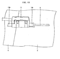
- FIG. 10 illustrates an example of mounting a connector for connecting a glass antenna formed on a surface of a glass substrate to a coaxial cable.
- This connector is brought into a state in which a holder portion and a pickup portion are detachably fit to each other.
- the holder portion is solder-connected to the glass antenna installed on the substrate.
- the pickup portion fit into the holder portion is connected to a coaxial cable.
- the connector is briefly described with reference to FIGS. 8A through 10 .
- FIG. 8A to 8F are views illustrating the holder portion of the connector.
- the holder portion 15 of the connector is constructed such that terminals are arranged on both sides of the bottom portion of an insulating case 14 formed into a rectangular parallelepiped shape whose two surfaces are opened.
- an earth terminal 13 is illustrated in a right-side part of the bottom view, while a feeding terminal 12 is illustrated in a left-side part thereof.
- the feeding terminal 12 has a connecting pin 12a erected towards the inside of an insulating case 14.
- the connecting pin 12a is connected to a core wire 23a of a coaxial cable 23 via a fitting terminal 25 of a pickup portion 21 illustrated in FIGS. 2A to 2F .
- the earth terminal 13 has two connection portions 13a which are respectively erected along the inner sides of both side surfaces of the insulating case 14. Each connection portion 13a is connected to an outer conductor 23b of the coaxial cable 23 via an earth conductor 24 of the pickup portion 21. Connection portions 12b and 13b of the terminals 12 and 13 connected to the glass antenna installed on the substrate are protrudingly provided at both end portions in the longer-side direction of the insulating case 14. Thus, soldering of the holder portion to the glass antenna installed on the substrate is facilitated.
- Each of the feeding terminal 12 and the earth terminal 13 is fixed to the insulating case 14 by an associated one of pairs 12c and 13c of connection portions erected so as to sandwich outer side surfaces of the insulating case 14.
- FIG. 9 is an explanatory view illustrating a state in which this connector is attached to the glass antenna installed on the glass substrate.
- a feeding portion of a radiating element 8 of the glass antenna installed on the glass substrate 5 is soldered to a mounting portion 12b of the feeding terminal 12 of the connector 11.
- An earth electrode 6 is soldered to a mounting portion 13b of the earth terminal 13.
- Parameters LD, pd, s0, and g0 representing the shape and the arrangement of the glass antenna are determined by the reception characteristic of the glass antenna.
- FIG. 10 shows a perspective view illustrating a state in which this connector is actually connected to the glass antenna installed on the glass substrate.
- Such a connector is disclosed as a commercial product in, e.g., GT 19 Series Connectors for Glass Antennas Catalog published by Hirose Electric Co., Ltd., pages 139 through 142 .
- JP-A-2008-035479 discloses a circuit-board-built-in connector obtained by incorporating a circuit board into a connector similar to the aforementioned connector for a glass antenna.
- JP-A-2004-031068 and JP-A-2005-110200 disclose the following connectors. That is, each of the connectors is constructed so that a holder portion thereof to be attached to a surface of a substrate, on which an antenna is installed, is adherently fixed thereto using a double-stick tape.
- each of the connectors has a pickup portion that is freely attachable to and detachable from the holder portion and that can be connected to the antenna utilizing an elastic force of a feeding terminal.
- each of the connectors can easily be fixed and attached thereto and detached therefrom.
- JP-A-2002-305062 discloses a connector device whose central conductor connected to a transmission line conductor (core wire) of a coaxial cable is slantingly connected to a surface of a substrate, on which an antenna is disposed, in order to prevent occurrence of a drastic change in the characteristic impedance of a signal transmission path of a connector portion.
- the connectors for connecting a glass antenna (hereinafter sometimes referred to simply as an antenna) disposed on a substrate to a transmission line such as a coaxial cable, as disclosed in the above-mentioned Glass Antennas Catalog and JP-A-2008-035479 , JP-A-2004-031068 and JP-A-2005-110200 are constructed without consideration of transmission loss due to impedance mismatching occurring in the connection portion between the antenna (conductor) installed on a glass surface and the connector at frequencies of high-frequency bands, more specifically, frequency bands such as an ultrahigh frequency (UHF) band and a microwave or super-high-frequency (SHF) band.
- UHF ultrahigh frequency
- SHF microwave or super-high-frequency
- the transmission loss of a signal transmitted from the antenna to a receiving apparatus through the coaxial cable is high, so that the signal cannot accurately be transmitted to the receiving apparatus.
- a feeding portion of the antenna using frequencies which correspond to a high-frequency band of a gigahertz (GHz) range
- the shape of the connection portion between the antenna installed on the glass surface and the connector non-negligibly affects wavelengths to be used.
- the connecting using the connector has a similar effect that the shape (or size) of the feeding portion which is an important composing element of the antenna is deformed. Consequently, sometimes, signal transmission characteristics are greatly affected.
- GPS global positioning system
- a connection angle at which the feeding portion of the antenna is connected to the feeding terminal of the connector is determined in consideration of the impedance of the transmission path.
- the accuracy and the reliability of the connection therebetween are problematic.
- assurance of durability is problematic.
- an object of the invention is to provide a connector that can suppress the transmission loss of a transmission line when an electric signal of a high-frequency band is transmitted, and that has reliability and durability when mounted on a substrate such as a vehicle window glass.
- Other objects of the invention are to provide an antenna on which this connector is installed, and to provide a vehicle window glass having this antenna.
- a connector including: a holder portion, attached to a glass antenna on a substrate, the holder portion including: a feeding terminal, having a predetermined width; and an earth terminal, disposed to surround both sides of the feeding terminal so that a predetermined distance is provided between the earth terminal and each of the both sides of the feeding terminal; and a pickup portion, detachably attached to the holder portion, the pickup portion including: a core wire conductor, which is connected to a core wire of a coaxial cable and which is connected to the feeding terminal when attached to the holder portion; and an earth conductor, which is connected to an outer conductor and which is connected to the earth terminal when attached to the holder portion, wherein a characteristic impedance of the connector when the pickup portion is attached to the holder portion is substantially equal to a characteristic impedance of the coaxial cable.
- the impedances of most coaxial cables used for television sets or the like are about 50 ohms ( ⁇ ) through 75 ⁇ .
- the impedance of the connector is designed assuming the coaxial cable to be used.
- the width of the feeding terminal thereof and the distance between the feeding terminal and each of parts of the earth terminal, which sandwich both sides of the feeding terminal are designed in consideration of the shapes and the properties of a substrate, on which the connector is attached, and a glass antenna.
- the width of the feeding terminal and the distance between the feeding terminal and the earth terminal are set so as not to affect the function of the coplanar waveguide line formed in the glass antenna.
- the connector according to the invention is a surface mounting type connector suitable for transmitting from antennas for receiving signals of high frequencies of a very high frequency (VHF) band, an ultrahigh frequency (UHF) band, a microwave or super-high-frequency (SHF) band, and the like, particularly, a glass antenna for receiving signals of frequencies of a GHz-band.
- the connector according to the invention is a surface mounting type connector enabled to be easily connected to a transmission line formed on a surface of a substrate, e.g., a feeding line of a glass antenna provided on a glass plate, so that the signal transmission loss of the transmission line including the connector and a coaxial cable connected thereto is low.
- This connector has a structure in which a holder portion and a pickup portion are detachably fittable to each other so that the coaxial cable can be easily attached to the substrate.
- the feeding terminal and the earth terminal of the connector may configure a coplanar waveguide line.
- the feeding terminal and the earth terminal which is disposed at a predetermined distance from each of both sides of the feeding terminal, are connected to the glass antenna, the feeding terminal and the earth terminal constitute a coplanar waveguide line.
- the characteristic impedance of the coplanar waveguide line is substantially equal to that of the coaxial cable, the feeding terminal hardly serves as an antenna for radio signals of high-frequencies.
- the feeding terminal serves substantially only as the transmission line.
- signals received from the antenna can efficiently be transmitted by the terminals, together with the coaxial cable, to the receiving apparatus.
- the terminals can undertake the role of the coplanar waveguide portion of the antenna.
- the earth terminal may include attaching portions provided protrudingly at both ends in a longer-side direction of an attaching surface of the holder portion, at which the holder portion is attached to the glass antenna, and the feeding terminal may include an attaching portion provided protrudingly in a shorter-side direction of the attaching surface of the holder portion, at which the holder portion is attached to the glass antenna.
- the connector is attached to the glass antenna, usually by soldering the feeding terminal and the earth terminal to the glass antenna.
- soldering the feeding terminal and the earth terminal to the glass antenna.
- the earth terminal has soldering portions at both ends in the longer-side direction of the connector.
- the feeding terminal has a soldering portion provided protrudingly in the shorter-side direction perpendicular to the longer-side direction. Consequently, the fixing of the connector to the substrate surface is strongly and reliably achieved.
- an antenna including: an antenna portion, including a linear radiating element and an earth electrode, the radiating element and the earth electrode being disposed on a dielectric substrate, wherein: the feeding terminal of the connector according to the above invention is connected to the radiating element; and the earth terminal of the connector is connected to the earth electrode.
- the antenna according to the invention is so-called a monopole antenna having an earth electrode and a single radiating element.
- This antenna can be designed so that transmission loss hardly occurs in a transmission line including a connector and a coaxial cable upon receiving the radio wave of high-frequency bands by the antenna. That is, the antenna according to the invention can be designed so that the characteristic impedance of an antenna portion has a desired value. The characteristic impedance of a part including the coaxial cable and the connector can easily be adjusted to that of the antenna portion.
- a part of the radiating element and the earth electrode may configure a coplanar waveguide line.
- the coplanar waveguide line is constructed such that the characteristic impedance of the antenna can be set at a desired value.
- the connector is connected to the coplanar waveguide line so as not to break the coplanar waveguide line, the length and the shape of a receiving portion of the antenna do not change, nor does the characteristic impedance of the antenna portion.
- signals corresponding to the received radio signals can be transmitted from the transmission line including the connector and the coaxial cable to the receiving apparatus without transmission loss.
- a vehicular window glass according to the invention is a glass substrate including the antenna of the above invention.
- the above glass antenna according to the invention is preferred as such an antenna.
- Vehicular antennas particularly need durability against vibrations and physical stress.
- the vehicular antennas require relatively-long-term durability.
- the vehicular window glass according to the invention can meet such requirements.
- vehicular receiving apparatuses or the like are used at locations where the radio wave condition of the received radio wave is not good.
- the vehicular window glass according to the invention can exercise excellent transmission performance in the transmission line connecting the antenna, the connector, and the coaxial cable. Consequently, good quality signals can be transmitted to the receiving apparatus.
- the invention can provide a connector that can suppress the transmission loss of a transmission line when an electric signal of a high-frequency band is transmitted, and that has reliability and durability when mounted on a substrate such as a vehicle window glass.
- the invention can provide an antenna on which this connector is installed, and a vehicular window glass having this antenna.
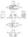
- FIGS. 1A to 1F show views illustrating the holder portion of the connector according to Embodiment 1 of the invention, FIG. 1A being a front view, FIG. 1B being a right side view, FIG. 1C being a left side view, FIG. 1D being a plan view, FIG. 1E being a bottom view, and FIG. 1F being a rear view.
- FIGS. 2A to 2E show views illustrating the pickup portion of the connector according to Embodiment 1 of the invention.
- FIG. 2F shows a cross-sectional view taken on line A-A' illustrated in FIG. 2D .
- the connector according to the present embodiment is described below with reference to FIGS. 1A to 2F .
- a holder portion 10 of this connector is constructed so that two terminals are arranged on a bottom portion of an insulating case 4 formed into a substantially hollow rectangular parallelepiped shape whose two surfaces are opened.
- the holder portion of the conventional connector illustrated in FIGS. 8A to 8F has the earth terminal 13 and the feeding terminal 12 respectively provided at both ends of the bottom surface.
- the holder portion 10 of the connector according to the present embodiment includes a feeding terminal 2 provided close to a central part of the bottom surface thereof, and an earth terminal 3 having opposed portions respectively provided at both sides of the feeding terminal 2 so that each of the opposed portions thereof is separated at a predetermined distance from an associated one of both sides of the feeding terminal 2.
- the width a of the feeding terminal 2 illustrated in the bottom view shown in FIG. 1E , and the distance b between both sides of the feeding terminal 2 and associated parts of the earth terminal 3 are designed so that when radio signals are transmitted from the antenna to a coaxial cable to which the antenna is connected by the connector, transmission loss of the signals is small. That is, when the connector connected to the coaxial cable is connected to a predetermined antenna, the feeding terminal 2 and the earth terminal 3, which serve as the connection portion between the antenna and the connector, have a coplanar waveguide line structure for radio signals to be received. Thus, a coplanar waveguide line portion of the feeding terminal 2 exhibits a predetermined characteristic impedance to received radio signals.
- the characteristic impedance of the transmission line constituted by connecting the connector to the coaxial cable can be set to be equal to that of the antenna.
- the width a of the feeding terminal 2 and the distance b between the feeding terminal 2 and the earth terminal 3 are set according to the shape of the antenna, to which the connector is connected, and the permittivity of the substrate. As will be described below, the width a and the distance b are designed by taking into consideration conditions for the antenna to which the connector is connected.
- the feeding terminal 2 has a connecting pin 2a erected towards the inside of an insulating case 4.
- the connecting pin 2a is connected to a core wire 23a of a coaxial cable 23 via a fitting terminal 25 of a pickup portion 21 illustrated in FIGS. 2A to 2F . Signals input to the feeding terminal 2 are transmitted to the coaxial cable 23.
- the earth terminal 3 has two connection portions 3a which are respectively erected along the inner sides of both side surfaces in shorter-side direction of the insulating case 4.
- Each connection portion 3a is connected to an outer conductor 23b of the coaxial cable 23 via a connection portion 24a and a fixing portion (crimping portion) 24b of an earth conductor 24 of the pickup portion 21 illustrated in FIGS. 2A to 2F .
- the connection portions 3a of a holder portion 10 are swollen towards the inner side of the insulating case 4.
- the connection portions 3a are connected thereto by pressing the connection portion 24a formed on side surfaces of the earth conductor 24 of the pickup portion 21 with an elastic force thereof.
- the connection portions 3a assure the certainty of electrical conduction.
- the connection portions 3a have the function of holding the pickup portion 21 when the pickup portion 21 is fit to the holder portion 10.
- connection portion 2b of the feeding terminal 2 with the glass antenna installed on the substrate is provided protrudingly in the direction of a rear surface (direction of a shorter-side of a rectangular shape in bottom view) of the insulating case 4.
- the connection portions 3b, 3b of the earth terminal 3 with the glass antenna installed on the substrate are protrudingly provided at both end portions in the direction of a side surface (direction of a longer-side of the rectangular shape in bottom view) of the insulating case 4.
- portions of the earth terminal 3 are fixed to the insulating case 4 with two pairs of fixing portions 3c and 3d thereof erected so as to sandwich the front surface and the rear surface (in the shorter-side direction) of the insulating case 4, respectively.
- such portions of the earth terminal 3, which are provided on both sides of the feeding terminal 2 are electrically conducted to each other.
- portions of the earth terminal 3 are separated from each other, there is no problem, because such portions are electrically conducted to each other when connected to the earth electrode.
- FIGS. 2A to 2E are views illustrating the pickup portion 21 of the connector according to the present embodiment, FIG. 2A being a front view, FIG. 2B being a right side view, FIG. 2C being a left side view, FIG. 2D being a plan view, and FIG. 2E being a bottom view.
- FIG. 2F is a cross-sectional view taken on line A-A' shown in FIG. 2D .
- the pickup portion 21 of_the connector according to the present embodiment is described with reference to FIGS. 2A to 2F .
- the pickup portion 21 includes a substantially parallelepiped hollow insulating case 22, an earth conductor 24, and a fitting terminal 25.
- the earth conductor 24 includes the connection portion 24a provided in the insulating case 22 so as to be connected to the connection portion 3a of the holder portion 10, and the fixing portion (crimping portion) 24b that crimps and performs the electrical conduction of an outer conductor 23b of the coaxial cable 23 introduced into the insulating case 22.
- the fitting terminal 25 is used to fit the core wire 23a of the coaxial cable 23 to the connecting pin 2a of the holder portion 10 to thereby transmit signals from the connecting pin 2a to the core wire 23a.
- the fitting terminal 25 is fixed in a fitting terminal fixing insulating case 26.
- the fitting terminal fixing insulating case 26 is fixed in the earth conductor 24 so as to be enclosed therein and includes a fitting portion 25a, which is fit onto the connection portion 2a of the holder portion 10, and a core wire fixing portion (crimping portion) 25b.
- the core wire fixing portion (crimping portion) 25b and the core wire 23a of the coaxial cable 23 are crimped and conducted to each other.
- the earth conductor 24 containing the fitting terminal 25 and the fitting terminal fixing insulating case 26 is fixed in the insulating case 22 so as to be enclosed therein.
- FIGS. 3A to 3F show views illustrating a holder portion 10' of a connector according to another embodiment 2 of the invention, FIG. 3A being a front view, FIG. 3B being a right side view, FIG. 3C being a left side view, FIG. 3d being a plan view, FIG. 3E being a bottom view, and FIG. 3F being a rear view. Differences between the connector illustrated in FIGS. 3A to 3F and that according to Embodiment 1 are described below.
- an earth terminal 3 of a holder portion 10' is formed of a single metal plate. Both end portions 3b, 3b of the earth terminal 3 are connected to each other.
- An insulating case 4 lacks for a bottom surface.
- Bottom portion fixing bars 4a and 4b are provided instead of a bottom surface.
- a feeding terminal 2 is fixed to the insulating case 4 by the bottom portion fixing bar 4b.
- the feeding terminal 2 does not protrude in the direction of the rear surface (a shorter-side direction in bottom view) of the insulating case 4 from the bottom portion thereof.
- the soldering of the feeding terminal 2 to a radiating element of an antenna is difficult to perform.
- the conduction of the radiating element of the antenna to the terminals can be assured utilizing an elastic force of the metallic feeding terminal 2 by soldering both end bonding portions 3b, 3b of the earth terminal to the glass antenna.
- the rest of the connector according to the present embodiment is substantially the same as an associated part of the connector according to Embodiment 1.
- the rest of the connector according to Embodiment 2 refer to the description of the associated part of the connector according to Embodiment 1.
- Embodiment 3 is a glass antenna having the above connector according to Embodiment 1 of the invention.
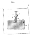
- FIG. 4 shows a layout drawing illustrating this antenna.
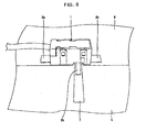
- FIG. 5 shows a perspective view illustrating the antenna of Embodiment 3 attached to a glass substrate 5 illustrated in FIG. 5 .
- this antenna is constructed so that an earth electrode 6 and a linear radiating element 7 are disposed on the glass substrate 5 which is a dielectric, and that a part of the radiating element 7 constitutes, together with the earth electrode 6, a coplanar waveguide line.
- the coplanar waveguide line (hereinafter referred to as a CPW line) is a transmission line in which a central conductor (a part of the radiating element 7 having a length Lt in this case) having a certain width disposed on the dielectric substrate is sandwiched from both sides thereof by opposed portions of an outer conductor (opposed parts of the earth electrode 6, which sandwich the central conductor in this case) so that each of the opposed portions is spaced at a predetermined distance from the central conductor.
- the central conductor can be set to be a transmission line having a specific characteristic impedance.
- the distance W between the central conductor and each of the opposed portions of the outer conductor is determined by the permittivity and the thickness of the dielectric substrate, the width s of the central conductor, the electric-conductivities of the central conductor and the outer conductor, and the like.
- the CPW line is formed in a range designated by "Lt" within the radiating element 7 illustrated in FIG. 4 .
- the CPW line is a transmission line constituted by the width s of the radiating element 7 and the distance W between the central conductor and each of the opposed portions of the earth electrode 6.
- a ratio of the width s of the central conductor to the distance W between the central conductor and each of the opposed portions of the earth electrode 6 is set, based on the thickness and the specific permittivity of the glass substrate 5, and the electric-conductivities of the central conductor and the earth conductor, so that the characteristic impedance has a predetermined value, e. g. , 50 ⁇ .
- Techniques for forming the CPW line have been known as described in detail in literatures (e.g. , K.C. Gupta, et al., "Microstrip Lines and Slotlines", Artech House ).
- the connector 1 is disposed on the glass substrate 5 so that a part of the feeding terminal 2, which is sandwiched between the opposed parts of the earth terminal 3, overlaps with the central conductor portion of the radiating element 7.
- the width of the feeding terminal 2 (the width a shown in FIGS. 1A to 1F ) is equal to or less than the width s of the central conductor.
- the distance ((a+2b) in the case illustrated in FIGS. 1A to 1F ) between the opposed portions of the earth terminal 3, which sandwich the feeding terminal 2 is equal to or larger than that ((s + 2W)) between the opposed portions of the outer conductor, which sandwich the central conductor. That is, the distance (b in the case illustrated in FIGS.
- the width of the feeding terminal 2 of the connector 1 and the distance between the feeding terminal 2 of the connector 1 and each of the opposed portions of the earth terminal 3 constitute the CPW line. Therefore, the width of the central conductor installed on the glass substrate 5 can be equal to or less than the value s. In addition, the distance between the central conductor and each of the opposed portions of the outer conductor can be equal to or more than the value W. To summarize these modes, when the central conductor and the outer conductor are connected to the feeding terminal 2 and the earth terminal 3, respectively, the connection portion between the central conductor and the feeding terminal 2 can be regarded as an integral central conductor.
- connection portion between the outer conductor and the earth terminal 3 can be regarded as an integral outer conductor.
- a part of the radiating element 7, in which the CPW line is not formed corresponds to a receiving portion for receiving radio signals.
- the attaching portions 3b at both end portions of the earth terminal 3 of the connector 1 are soldered to the earth electrode 6.
- the attaching portion 2b of the feeding terminal 2 is soldered to the receiving portion of the radiating element 7. Consequently, the reliable fixing of the connector 1 onto the glass substrate 5, and the reliable connection between the radiating element 7 and the feeding terminal 2 and between the earth electrode 6 and the earth terminal 3 can be implemented.
- a CPW line is formed such that the radiating element 7 and the feeding terminal 2 are integrated with each other, and that the earth terminal 3 and a part of the earth electrode 6 are integrated with each other. Accordingly, it is unnecessary to arrange a CPW line formation portion of the connector 1 and another CPW line formation portion constituted by the radiating element 7 and the earth electrode 6 by exactly adjusting. Consequently, the connector 1 may be disposed by being deviated in the longer-side direction of the radiating element 7. In addition, the length of the (signal) receiving portion Le of the radiating element 7 can be adjusted.
- connection portion of the feeding terminal 2 on the glass substrate 5 has the form of a CPW line.
- the distance between the connecting pin 2a and the fitting terminal 25 of the connector 1 is short.
- the characteristic impedance of the CPW line of the connection portion of the feeding terminal 2 is set to be substantially the same as that (usually, about 50 ⁇ ) of the characteristic impedance of the coaxial cable. Consequently, the transmission loss of the transmission line extending from the antenna to the receiving apparatus can be reduced.
- a CPW line is constructed in a part of the earth electrode 6 within a range designated by "Lt".
- the central conductor of the CPW line is extended to form a monopole antenna.
- the shape of the radiating element is not limited to that of the central conductor.
- the width of a part of length Le of the radiating element 7 can be wide, as compared with the width s of the central conductor constituting the CPW line within the range designated by "Lt".
- the width of the radiating element 7 can be gradually increased from that s.
- the antenna can be formed to be a wideband antenna.
- the radiating element 7 can spread like a fan shape.
- the radiating element 7 can be branched into a plurality of elements.
- an antenna pattern capable of receiving signals of frequencies of a desired frequency band is formed. Accordingly, the antenna can be formed to be a wideband or multi-band antenna.
- the length Lt of the CPW line portion can optionally be selected in consideration of transmission loss.
- any window glass such as a vehicular front window glass (windowscreen), a door window glass, a side window glass, and a rear window glass
- a glass substrate on which an antenna according to the invention is mounted can be employed as a glass substrate on which an antenna according to the invention is mounted.
- an architectural glass can be employed as the glass substrate.
- the glass substrate according to the invention is not limited to a specific glass.
- at least a part of the radiating element 7 and the earth electrode 6 are formed on a optically-opaque coating. Thus, only a thin straight-line portion of the radiating element 7 is viewed from a vehicular exterior side. This is preferable in respect of the design of a vehicle.
- the conductors (the earth electrode 6 and the radiating element 7) provided on the glass substrate 5 are formed by printing a paste containing an electrically conductive metal, such as a silver paste, on a vehicle interior side of a glass plate and then firing the printed paste.
- a method of forming the conductors on the glass substrate according to the invention is not limited to this forming method.
- the conductors can be formed by forming a linear element or a foil element, which is made of an electrically conductive material such as copper, on the glass substrate.
- such conductors can be formed on the glass substrate by an adhesive or the like.
- the conductor on the glass substrate 5 is a silver conductor
- the conductor can be formed by providing a conductor layer in or on a surface of a synthetic resin film and forming the synthetic resin film with the conductor layer on the glass substrate.
- the conductor on the glass substrate can be formed by forming a flexible circuit board, on which the conductor is formed.
- a optically-opaque coating can be formed on the glass substrate 5, and then the radiating element 7 and the earth electrode 6 can be partly or entirely provided on the optically-opaque coating. Ceramics such as a black enamel can be cited as the material of the optically-opaque coating.
- the glass substrate 5 is applied to a vehicle and used as a window glass, when viewed from a vehicle exterior side of the window glass, the conductor provided on the optically-opaque coating is prevented by the optically-opaque coating from being seen from the vehicle exterior side of the window glass.
- the window glass excels in design.
- the glass antenna is not necessarily installed on the glass substrate.
- the glass antenna can be installed on a substrate, such as a transparent plastic substrate, which is similar to the glass substrate.
- the connector 1 including the holder portion illustrated in FIGS. 1A to 1F and the pickup portion illustrated in FIGS. 2A to 2F was manufactured.
- the connecting pin 2a of the feeding terminal 2 was not cylindrically shaped.
- the connecting pin 2a of the feeding terminal 2 was a square-pole-like pin like the attaching portion 2b of the feeding terminal 2.
- the width a of the feeding terminal 2 of the connector 1 illustrated in FIGS. 1A to 1F was set at 2 mm.
- the distance b between the feeding terminal 2 and each of the opposed portions of the earth terminal 3 was set at 2 mm.
- FIGS. 2A to 2F a coaxial cable whose characteristic impedance was 50 ⁇ was connected to the pickup portion 21 of the manufactured connector 1.
- the feeding terminal 2 and the earth terminal 3 of the connector 1 were respectively fixed by soldering to the feeding portion and the earth electrode 6 of the glass antenna installed on the glass substrate.
- FIG. 5 shows a perspective view illustrating the antenna that has the connector 1 installed on the glass substrate.
- the glass substrate 5 was 3.5 mm in thickness.
- the earth electrode 6 was formed using a copper foil which was 300 mm long and 150 mm wide.
- a CPW line structure and a quarter-wavelength monopole antenna element which resonants at about 1.5GHz were formed at a central portion of a side of the earth electrode 6.
- the values of the dimensions of the following parts described in FIG. 4 are as follows. s: 3 mm,
- the manufactured connector 1 was installed at a position indicated by dashed lines on the glass substrate 5 and mounted by being soldered thereto.
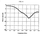
- the measurement of return loss which was one of antenna characteristics was performed.
- the return loss at 1.55 GHz is -16dB (a voltage standing wave ratio is 1.38).
- a voltage standing wave ratio is 1.38.
- the characteristic impedance of the CPW line was 55 ⁇ .
- the width s and the distance w to the earth electrode 6 were determined under the thickness of glass and those of the conductors such that the characteristic impedance is 50 ⁇ .
- a target value of the characteristic impedance is set at 55 ⁇ substantially close to 50 ⁇ , in consideration of mountability and soldering workability.
- the width s of the radiating element 7 and the distance w between the central conductor and each of the opposed portions of the earth electrode 6 can be determined and changed from the above values in view of the thickness of glass, the width of the radiating element 7, the mountability and the soldering workability so that the characteristic impedance is set at 75 ⁇ similarly.
- the shape of the earth electrode 6 was set according to the present example.
- the shape of the earth electrode 6 can optionally be changed in view of the characteristic according to the shape of the glass plate and the used frequency, and can be changed into a mesh-like shape.
- the attaching portion 3b of the earth terminal 3 according to the present embodiment had a soldering area, similarly to the conventional connector. Thus, the attaching portion 3b had proof stress against an external force.
- the wiring direction of the coaxial cable 23 was similar to that in the case of using the conventional connector. Accordingly, the connector according to the present examle can favorably be utilized as a connector for the glass antenna on the vehicular window glass.
- FIG. 10 shows a perspective view illustrating a connector (a holder portion had a structure illustrated in FIGS. 8A to 8F , while a pickup portion had a structure illustrated in FIGS. 2A to 2F ).
- the radiating element 8 was disposed so as to be separated at a distance g0 from the earth electrode 6 so that the feeding portion was disposed at the side of the earth electrode 6, and that the receiving portion was located away from the earth electrode 6, as illustrated in FIG. 9 .
- a combination of the radiating element 8 and the earth electrode 6 was formed to be a monopole antenna. The values of the dimensions of the following parts described in FIG. 9 are as follows.
- the holder portion 15 of the connector illustrated in FIG. 10 was mounted at a position indicated by dashed lines shown in FIG. 9 by being soldered thereto.
- the mounting portion 12b of the feeding terminal 12 of the holder portion and the mounting portion 13b of the earth terminal 13 were connected to the feeding portion of the radiating element 8 and the earth electrode 6, respectively.
- the pickup portion 21, to which the coaxial cable 23 was connected, was connected to the holder portion 15.
- High-frequency signals received by the glass antenna were transmitted to the coaxial cable 23.
- Measurement of return loss of this transmission line was performed, similarly to the example according to the invention. As is understood from results of the measurement shown in FIG. 7 , the level of the return loss was substantially flat on the whole in the GHz frequency range. Sufficient resonance was not observed. Thus, it is evaluated that the antenna performance cannot be exercised.
- the connector according to the invention is utilized as a connector for a vehicular glass antenna which receives the digital terrestrial television broadcast (which uses frequencies ranging from 470 megahertz (MHz) to 862 MHz), and the UHF-band analog television broadcast, digital television broadcast, and digital radio broadcast (which use frequencies ranging from 170 MHz to 230 MHz) in Japan, South Korea, China, Brazil, the United States of America, Europe and the like.
- digital terrestrial television broadcast which uses frequencies ranging from 470 megahertz (MHz) to 862 MHz
- UHF-band analog television broadcast, digital television broadcast, and digital radio broadcast which use frequencies ranging from 170 MHz to 230 MHz
- the connector according to the invention is utilized also as a connector for a vehicular glass antenna which receives the frequency-modulation (FM) band analog radio broadcast (which uses frequencies ranging from 76 MHz to 90 MHz) in Japan, the FM-band analog radio broadcast (which uses frequencies ranging from 88 MHz to 108 MHz) in the United States of America and the VHF-band analog television broadcast (which uses frequencies ranging from 90 MHz to 108 MHz and from 170 MHz to 222 MHz).
- FM frequency-modulation
- VHF-band analog television broadcast which uses frequencies ranging from 90 MHz to 108 MHz and from 170 MHz to 222 MHz.
- the connector according to the invention is utilized also as a connector for a glass antenna which receives the broadcast and communication at frequencies in the 800 MHz band for mobile phones (which use frequencies ranging from 810 MHz to 960 MHz), the 1.5 GHz band for mobile phones (which use frequencies ranging from 1.429 GHz to 1.501 GHz), the 1.9 GHz band for mobile phones (which use frequencies ranging from 1.850 GHz to 1.990 GHz), the global positioning system (GPS) (which uses a frequency of 1,575.42 MHz), the vehicle information and communication system (VICS (trademark)) (which uses a frequency of 2.5 GHz), the electronic toll collection system (ETC (non-stop automatic fare collection system)) (which uses frequencies of the 5.8 GHz band), the dedicated short range communication (DSRC) (which uses frequencies of the 915 MHz band and the 5.8 GHz band), communication for the automotive keyless entry system (which uses frequencies ranging from 300 MHz to 450 MHz), and communication for the satellite digital audio radio service (SDARS) (which uses frequencies
- the connector according to the invention can be utilized as a surface mounting type connector suitable for broadcast and communication using signals of high frequencies of a very high frequency (VHF) band (whose frequencies range from 30 MHz to 300 MHz), an ultrahigh frequency (UHF) band (whose frequencies range from 300 MHz to 3 GHz), a microwave (SHF) band (whose frequencies range from 3 GHz to 30 GHz).
- VHF very high frequency
- UHF ultrahigh frequency
- SHF microwave
- the antenna according to the invention is easily fixed to an insulating substrate, such as a glass substrate, and constructed to be strong.
- the antenna according to the invention has resistance to vibrations, and durability.
- the antenna according to the invention is suitable for a glass antenna mounted on a vehicular window glass.
Abstract
Description
- The present invention relates to a connector, an antenna provided with the connector, and a vehicular window glass provided with the antenna.
- What is called a glass antenna installed on a window glass or the like is known as a vehicle-mounted antenna. The glass antenna is constructed by placing a linear conductor on a surface of a dielectric substrate such as the window glass. Radio signals received by the antenna are transmitted by a transmission line such as a coaxial cable to a receiving apparatus such as a television receiver. Various connectors for connecting the antenna and the coaxial cable to each other are known.
-
FIG. 10 illustrates an example of mounting a connector for connecting a glass antenna formed on a surface of a glass substrate to a coaxial cable. This connector is brought into a state in which a holder portion and a pickup portion are detachably fit to each other. The holder portion is solder-connected to the glass antenna installed on the substrate. The pickup portion fit into the holder portion is connected to a coaxial cable. The connector is briefly described with reference toFIGS. 8A through 10 .FIG. 8A to 8F are views illustrating the holder portion of the connector. - As illustrated in
FIGS. 8A to 8F , theholder portion 15 of the connector is constructed such that terminals are arranged on both sides of the bottom portion of aninsulating case 14 formed into a rectangular parallelepiped shape whose two surfaces are opened. As viewed in a bottom view shown inFIGS. 8A to 8F , anearth terminal 13 is illustrated in a right-side part of the bottom view, while afeeding terminal 12 is illustrated in a left-side part thereof. Thefeeding terminal 12 has a connectingpin 12a erected towards the inside of aninsulating case 14. The connectingpin 12a is connected to a core wire 23a of acoaxial cable 23 via afitting terminal 25 of apickup portion 21 illustrated inFIGS. 2A to 2F . Thus, signals are transmitted to the coaxial cable 23 (the structure of thepickup portion 21 is similar to that illustrated inFIGS. 2A to 2F ). Theearth terminal 13 has twoconnection portions 13a which are respectively erected along the inner sides of both side surfaces of theinsulating case 14. Eachconnection portion 13a is connected to anouter conductor 23b of thecoaxial cable 23 via anearth conductor 24 of thepickup portion 21.Connection portions terminals insulating case 14. Thus, soldering of the holder portion to the glass antenna installed on the substrate is facilitated. Each of thefeeding terminal 12 and theearth terminal 13 is fixed to the insulatingcase 14 by an associated one ofpairs insulating case 14. -
FIG. 9 is an explanatory view illustrating a state in which this connector is attached to the glass antenna installed on the glass substrate. A feeding portion of a radiatingelement 8 of the glass antenna installed on theglass substrate 5 is soldered to amounting portion 12b of thefeeding terminal 12 of theconnector 11. Anearth electrode 6 is soldered to a mountingportion 13b of theearth terminal 13. Parameters LD, pd, s0, and g0 representing the shape and the arrangement of the glass antenna are determined by the reception characteristic of the glass antenna.FIG. 10 shows a perspective view illustrating a state in which this connector is actually connected to the glass antenna installed on the glass substrate. - Such a connector is disclosed as a commercial product in, e.g., GT 19 Series Connectors for Glass Antennas Catalog published by Hirose Electric Co., Ltd., pages 139 through 142. In addition,
JP-A-2008-035479 JP-A-2004-031068 JP-A-2005-110200 - On the other hand,
JP-A-2002-305062 - The connectors for connecting a glass antenna (hereinafter sometimes referred to simply as an antenna) disposed on a substrate to a transmission line such as a coaxial cable, as disclosed in the above-mentioned Glass Antennas Catalog and
JP-A-2008-035479 JP-A-2004-031068 JP-A-2005-110200 - Radio signals used in digital terrestrial television broadcasting, digital television broadcasting in an European Union region, digital radio broadcasting, and a global positioning system (GPS) often utilize a high-frequency band of a UHF band. Thus, in the transmission path of signals transmitted from a receiving antenna for receiving signals of a high-frequency band, it is necessary to design a connector in consideration of the impedance matching between the coaxial cable and the connector, more particularly, the shapes and the properties of the antenna and the substrate to be connected thereto.
- In the case of the connector device disclosed in
JP-A-2002-305062 - On the other hand, various connectors to be connected to a coaxial cable are known, which are mounted on printed circuit boards. However, it is not considered that such connectors are mounted on substrates, such as a vehicle window glass, to which vibrations and external stress can be applied. The fittability and the holding force of the connector are insufficient. More particularly, the durability of the mounted connector against external stress is insufficient.
- In view of the above problems, an object of the invention is to provide a connector that can suppress the transmission loss of a transmission line when an electric signal of a high-frequency band is transmitted, and that has reliability and durability when mounted on a substrate such as a vehicle window glass. Other objects of the invention are to provide an antenna on which this connector is installed, and to provide a vehicle window glass having this antenna.
- According to an aspect of the invention, there is provided a connector, including: a holder portion, attached to a glass antenna on a substrate, the holder portion including: a feeding terminal, having a predetermined width; and an earth terminal, disposed to surround both sides of the feeding terminal so that a predetermined distance is provided between the earth terminal and each of the both sides of the feeding terminal; and a pickup portion, detachably attached to the holder portion, the pickup portion including: a core wire conductor, which is connected to a core wire of a coaxial cable and which is connected to the feeding terminal when attached to the holder portion; and an earth conductor, which is connected to an outer conductor and which is connected to the earth terminal when attached to the holder portion, wherein a characteristic impedance of the connector when the pickup portion is attached to the holder portion is substantially equal to a characteristic impedance of the coaxial cable.
- The impedances of most coaxial cables used for television sets or the like are about 50 ohms (Ω) through 75 Ω. The impedance of the connector is designed assuming the coaxial cable to be used. When a specific connector according to the invention is designed, the width of the feeding terminal thereof and the distance between the feeding terminal and each of parts of the earth terminal, which sandwich both sides of the feeding terminal, are designed in consideration of the shapes and the properties of a substrate, on which the connector is attached, and a glass antenna. For example, the width of the feeding terminal and the distance between the feeding terminal and the earth terminal are set so as not to affect the function of the coplanar waveguide line formed in the glass antenna.
- The connector according to the invention is a surface mounting type connector suitable for transmitting from antennas for receiving signals of high frequencies of a very high frequency (VHF) band, an ultrahigh frequency (UHF) band, a microwave or super-high-frequency (SHF) band, and the like, particularly, a glass antenna for receiving signals of frequencies of a GHz-band. More specifically, the connector according to the invention is a surface mounting type connector enabled to be easily connected to a transmission line formed on a surface of a substrate, e.g., a feeding line of a glass antenna provided on a glass plate, so that the signal transmission loss of the transmission line including the connector and a coaxial cable connected thereto is low. This connector has a structure in which a holder portion and a pickup portion are detachably fittable to each other so that the coaxial cable can be easily attached to the substrate.
- According to another aspect of the invention, the feeding terminal and the earth terminal of the connector may configure a coplanar waveguide line.
- When the feeding terminal and the earth terminal, which is disposed at a predetermined distance from each of both sides of the feeding terminal, are connected to the glass antenna, the feeding terminal and the earth terminal constitute a coplanar waveguide line. When the characteristic impedance of the coplanar waveguide line is substantially equal to that of the coaxial cable, the feeding terminal hardly serves as an antenna for radio signals of high-frequencies. The feeding terminal serves substantially only as the transmission line. Thus, signals received from the antenna can efficiently be transmitted by the terminals, together with the coaxial cable, to the receiving apparatus. In addition, in the connection portion between the glass antenna and the connector, the terminals can undertake the role of the coplanar waveguide portion of the antenna.
- According to another aspect of the invention, the earth terminal may include attaching portions provided protrudingly at both ends in a longer-side direction of an attaching surface of the holder portion, at which the holder portion is attached to the glass antenna, and the feeding terminal may include an attaching portion provided protrudingly in a shorter-side direction of the attaching surface of the holder portion, at which the holder portion is attached to the glass antenna.
- The connector is attached to the glass antenna, usually by soldering the feeding terminal and the earth terminal to the glass antenna. When a part of each of the feeding terminal and the earth terminal is provided protrudingly from the attaching surface of the connector, the soldering of the terminals to the antenna is easily achieved. The reliable soldering of the terminals to the antenna is achieved. In addition, the earth terminal has soldering portions at both ends in the longer-side direction of the connector. The feeding terminal has a soldering portion provided protrudingly in the shorter-side direction perpendicular to the longer-side direction. Consequently, the fixing of the connector to the substrate surface is strongly and reliably achieved.
- According to another aspect of the invention, there is provided an antenna, including: an antenna portion, including a linear radiating element and an earth electrode, the radiating element and the earth electrode being disposed on a dielectric substrate, wherein: the feeding terminal of the connector according to the above invention is connected to the radiating element; and the earth terminal of the connector is connected to the earth electrode.
- The antenna according to the invention is so-called a monopole antenna having an earth electrode and a single radiating element. This antenna can be designed so that transmission loss hardly occurs in a transmission line including a connector and a coaxial cable upon receiving the radio wave of high-frequency bands by the antenna. That is, the antenna according to the invention can be designed so that the characteristic impedance of an antenna portion has a desired value. The characteristic impedance of a part including the coaxial cable and the connector can easily be adjusted to that of the antenna portion.
- According to another aspect of the invention, a part of the radiating element and the earth electrode may configure a coplanar waveguide line.
- The coplanar waveguide line is constructed such that the characteristic impedance of the antenna can be set at a desired value. Thus, when the connector is connected to the coplanar waveguide line so as not to break the coplanar waveguide line, the length and the shape of a receiving portion of the antenna do not change, nor does the characteristic impedance of the antenna portion. Thus, after radio signals of predetermined high frequencies are received from the antenna, signals corresponding to the received radio signals can be transmitted from the transmission line including the connector and the coaxial cable to the receiving apparatus without transmission loss.
- A vehicular window glass according to the invention is a glass substrate including the antenna of the above invention. Most of receiving apparatuses of television sets or the like and communication apparatuses mounted on vehicles need antennas. Recently, there have been many antennas respectively installed on window glasses. The above glass antenna according to the invention is preferred as such an antenna. Vehicular antennas particularly need durability against vibrations and physical stress. In addition, the vehicular antennas require relatively-long-term durability. The vehicular window glass according to the invention can meet such requirements. In addition, vehicular receiving apparatuses or the like are used at locations where the radio wave condition of the received radio wave is not good. Thus, the vehicular window glass according to the invention can exercise excellent transmission performance in the transmission line connecting the antenna, the connector, and the coaxial cable. Consequently, good quality signals can be transmitted to the receiving apparatus.
- The invention can provide a connector that can suppress the transmission loss of a transmission line when an electric signal of a high-frequency band is transmitted, and that has reliability and durability when mounted on a substrate such as a vehicle window glass. In addition, the invention can provide an antenna on which this connector is installed, and a vehicular window glass having this antenna.
- The present invention will become more fully understood from the detailed description given hereinbelow and the accompanying drawing which is given by way of illustration only, and thus is not limitative of the present invention and wherein:
-
FIGS. 1A to 1F are views illustrating a holder portion of a connector according to an embodiment of the invention,FIG. 1A being a front view,FIG. 1B being a right side view,FIG. 1C being a left side view,FIG. 1D being a plan view,FIG. 1E being a bottom view, andFIG. 1F being a rear view; -
FIGS. 2A to 2E are views illustrating a pickup portion of the connector according to the embodiment of the invention,FIG. 2A being a front view,FIG. 2B being a right side view,FIG. 2C being a left side view,FIG. 2D being a plan view, andFIG. 2E being a bottom view; -
FIG. 2F is a cross-sectional view taken on line A-A' shown inFIG. 2D ; -
FIGS. 3A to 3F are views illustrating a holder portion of a connector according to another embodiment of the invention,FIG. 3A being a front view,FIG. 3B being a right side view,FIG. 3C being a left side view,FIG. 3d being a plan view,FIG. 3E being a bottom view, andFIG. 3F being a rear view; -
FIG. 4 is a layout drawing illustrating an antenna provided with a connector according to the invention; -
FIG. 5 is a perspective view illustrating an example of installation of a connector according to the invention in an antenna; -
FIG. 6 is a graph illustrating return loss versus GHz-band frequencies of a transmission line obtained by connecting the connector according to the invention to a coaxial cable; -
FIG. 7 is a graph illustrating return loss versus GHz-band frequencies of a transmission line obtained by connecting a conventional connector to a coaxial cable; -
FIGS. 8A to 8F are views illustrating a holder portion of the conventional connector,FIG. 8A being a front view,FIG. 8B being a right side view,FIG. 8C being a left side view,FIG. 8D being a plan view,FIG. 8E being a bottom view, andFIG. 8F being a rear view; -
FIG. 9 is a layout drawing illustrating an antenna provided with the conventional connector; and -
FIG. 10 is a perspective view illustrating an example of installation of the conventional connector in an antenna. - The invention is described hereinafter based on specific embodiments with reference to the accompanying drawings. However, the invention is not limited to the embodiments and examples. The embodiments and the examples can be changed or modified without departing from the spirit and the scope of the invention.
- A connector according to the invention is constructed so that a holder portion and a pickup portion thereof can be detachably fit to each other.
FIGS. 1A to 1F show views illustrating the holder portion of the connector according toEmbodiment 1 of the invention,FIG. 1A being a front view,FIG. 1B being a right side view,FIG. 1C being a left side view,FIG. 1D being a plan view,FIG. 1E being a bottom view, andFIG. 1F being a rear view.FIGS. 2A to 2E show views illustrating the pickup portion of the connector according toEmbodiment 1 of the invention.FIG. 2F shows a cross-sectional view taken on line A-A' illustrated inFIG. 2D . The connector according to the present embodiment is described below with reference toFIGS. 1A to 2F . - As illustrated in
FIGS. 1A to 1F , aholder portion 10 of this connector is constructed so that two terminals are arranged on a bottom portion of an insulatingcase 4 formed into a substantially hollow rectangular parallelepiped shape whose two surfaces are opened. The holder portion of the conventional connector illustrated inFIGS. 8A to 8F has theearth terminal 13 and the feedingterminal 12 respectively provided at both ends of the bottom surface. However, theholder portion 10 of the connector according to the present embodiment includes a feedingterminal 2 provided close to a central part of the bottom surface thereof, and anearth terminal 3 having opposed portions respectively provided at both sides of the feedingterminal 2 so that each of the opposed portions thereof is separated at a predetermined distance from an associated one of both sides of the feedingterminal 2. - The width a of the feeding
terminal 2 illustrated in the bottom view shown inFIG. 1E , and the distance b between both sides of the feedingterminal 2 and associated parts of theearth terminal 3 are designed so that when radio signals are transmitted from the antenna to a coaxial cable to which the antenna is connected by the connector, transmission loss of the signals is small. That is, when the connector connected to the coaxial cable is connected to a predetermined antenna, the feedingterminal 2 and theearth terminal 3, which serve as the connection portion between the antenna and the connector, have a coplanar waveguide line structure for radio signals to be received. Thus, a coplanar waveguide line portion of the feeding terminal 2 exhibits a predetermined characteristic impedance to received radio signals. The characteristic impedance of the transmission line constituted by connecting the connector to the coaxial cable can be set to be equal to that of the antenna. The width a of the feedingterminal 2 and the distance b between the feedingterminal 2 and theearth terminal 3 are set according to the shape of the antenna, to which the connector is connected, and the permittivity of the substrate. As will be described below, the width a and the distance b are designed by taking into consideration conditions for the antenna to which the connector is connected. - The feeding
terminal 2 has a connectingpin 2a erected towards the inside of an insulatingcase 4. The connectingpin 2a is connected to a core wire 23a of acoaxial cable 23 via afitting terminal 25 of apickup portion 21 illustrated inFIGS. 2A to 2F . Signals input to the feedingterminal 2 are transmitted to thecoaxial cable 23. - The
earth terminal 3 has twoconnection portions 3a which are respectively erected along the inner sides of both side surfaces in shorter-side direction of the insulatingcase 4. Eachconnection portion 3a is connected to anouter conductor 23b of thecoaxial cable 23 via aconnection portion 24a and a fixing portion (crimping portion) 24b of anearth conductor 24 of thepickup portion 21 illustrated inFIGS. 2A to 2F . As illustrated inFIG. 1B , theconnection portions 3a of aholder portion 10 are swollen towards the inner side of the insulatingcase 4. Theconnection portions 3a are connected thereto by pressing theconnection portion 24a formed on side surfaces of theearth conductor 24 of thepickup portion 21 with an elastic force thereof. Thus, theconnection portions 3a assure the certainty of electrical conduction. In addition, theconnection portions 3a have the function of holding thepickup portion 21 when thepickup portion 21 is fit to theholder portion 10. - As illustrated in
FIGS. 1A to 1F , theconnection portion 2b of the feedingterminal 2 with the glass antenna installed on the substrate is provided protrudingly in the direction of a rear surface (direction of a shorter-side of a rectangular shape in bottom view) of the insulatingcase 4. Theconnection portions earth terminal 3 with the glass antenna installed on the substrate are protrudingly provided at both end portions in the direction of a side surface (direction of a longer-side of the rectangular shape in bottom view) of the insulatingcase 4. Thus, the soldering of the feeding portion and the earth electrode of the radiating element of the glass antenna installed on the substrate is facilitated. In addition, both ends in the longer-side direction of the bottom surface of theholder portion 10 are soldered to the substrate. Consequently, the strength and the durability of bonding the connector to the substrate are assured. - As illustrated in
FIGS. 1A to 1F , portions of theearth terminal 3 are fixed to the insulatingcase 4 with two pairs of fixingportions case 4, respectively. Preferably, such portions of theearth terminal 3, which are provided on both sides of the feedingterminal 2, are electrically conducted to each other. However, when such portions of theearth terminal 3 are separated from each other, there is no problem, because such portions are electrically conducted to each other when connected to the earth electrode. -
FIGS. 2A to 2E are views illustrating thepickup portion 21 of the connector according to the present embodiment,FIG. 2A being a front view,FIG. 2B being a right side view,FIG. 2C being a left side view,FIG. 2D being a plan view, andFIG. 2E being a bottom view.FIG. 2F is a cross-sectional view taken on line A-A' shown inFIG. 2D . Thepickup portion 21 of_the connector according to the present embodiment is described with reference toFIGS. 2A to 2F . Thepickup portion 21 includes a substantially parallelepiped hollow insulatingcase 22, anearth conductor 24, and afitting terminal 25. Theearth conductor 24 includes theconnection portion 24a provided in the insulatingcase 22 so as to be connected to theconnection portion 3a of theholder portion 10, and the fixing portion (crimping portion) 24b that crimps and performs the electrical conduction of anouter conductor 23b of thecoaxial cable 23 introduced into the insulatingcase 22. Thefitting terminal 25 is used to fit the core wire 23a of thecoaxial cable 23 to the connectingpin 2a of theholder portion 10 to thereby transmit signals from the connectingpin 2a to the core wire 23a. - The
fitting terminal 25 is fixed in a fitting terminal fixing insulatingcase 26. The fitting terminal fixing insulatingcase 26 is fixed in theearth conductor 24 so as to be enclosed therein and includes afitting portion 25a, which is fit onto theconnection portion 2a of theholder portion 10, and a core wire fixing portion (crimping portion) 25b. The core wire fixing portion (crimping portion) 25b and the core wire 23a of thecoaxial cable 23 are crimped and conducted to each other. Theearth conductor 24 containing thefitting terminal 25 and the fitting terminal fixing insulatingcase 26 is fixed in the insulatingcase 22 so as to be enclosed therein. -
FIGS. 3A to 3F show views illustrating a holder portion 10' of a connector according to anotherembodiment 2 of the invention,FIG. 3A being a front view,FIG. 3B being a right side view,FIG. 3C being a left side view,FIG. 3d being a plan view,FIG. 3E being a bottom view, andFIG. 3F being a rear view. Differences between the connector illustrated inFIGS. 3A to 3F and that according toEmbodiment 1 are described below. In the connector illustrated inFIGS. 3A to 3F , anearth terminal 3 of a holder portion 10' is formed of a single metal plate. Bothend portions earth terminal 3 are connected to each other. An insulatingcase 4 lacks for a bottom surface. Bottomportion fixing bars terminal 2 is fixed to the insulatingcase 4 by the bottomportion fixing bar 4b. The feedingterminal 2 does not protrude in the direction of the rear surface (a shorter-side direction in bottom view) of the insulatingcase 4 from the bottom portion thereof. When the feedingterminal 2 does not protrude from the bottom portion of the insulatingcase 4, the soldering of the feedingterminal 2 to a radiating element of an antenna is difficult to perform. However, the conduction of the radiating element of the antenna to the terminals can be assured utilizing an elastic force of themetallic feeding terminal 2 by soldering bothend bonding portions Embodiment 1. Thus, regarding the rest of the connector according toEmbodiment 2, refer to the description of the associated part of the connector according toEmbodiment 1. -
Embodiment 3 is a glass antenna having the above connector according toEmbodiment 1 of the invention.FIG. 4 shows a layout drawing illustrating this antenna.FIG. 5 shows a perspective view illustrating the antenna ofEmbodiment 3 attached to aglass substrate 5 illustrated inFIG. 5 . As illustrated inFIG. 4 , this antenna is constructed so that anearth electrode 6 and alinear radiating element 7 are disposed on theglass substrate 5 which is a dielectric, and that a part of the radiatingelement 7 constitutes, together with theearth electrode 6, a coplanar waveguide line. The coplanar waveguide line (hereinafter referred to as a CPW line) is a transmission line in which a central conductor (a part of the radiatingelement 7 having a length Lt in this case) having a certain width disposed on the dielectric substrate is sandwiched from both sides thereof by opposed portions of an outer conductor (opposed parts of theearth electrode 6, which sandwich the central conductor in this case) so that each of the opposed portions is spaced at a predetermined distance from the central conductor. When an earth conductor is used as the outer conductor, the central conductor can be set to be a transmission line having a specific characteristic impedance. The distance W between the central conductor and each of the opposed portions of the outer conductor is determined by the permittivity and the thickness of the dielectric substrate, the width s of the central conductor, the electric-conductivities of the central conductor and the outer conductor, and the like. The CPW line is formed in a range designated by "Lt" within the radiatingelement 7 illustrated inFIG. 4 . The CPW line is a transmission line constituted by the width s of the radiatingelement 7 and the distance W between the central conductor and each of the opposed portions of theearth electrode 6. A ratio of the width s of the central conductor to the distance W between the central conductor and each of the opposed portions of theearth electrode 6 is set, based on the thickness and the specific permittivity of theglass substrate 5, and the electric-conductivities of the central conductor and the earth conductor, so that the characteristic impedance has a predetermined value, e. g. , 50Ω. Techniques for forming the CPW line have been known as described in detail in literatures (e.g. , K.C. Gupta, et al., "Microstrip Lines and Slotlines", Artech House). - The
connector 1 is disposed on theglass substrate 5 so that a part of the feedingterminal 2, which is sandwiched between the opposed parts of theearth terminal 3, overlaps with the central conductor portion of the radiatingelement 7. At that time, the width of the feeding terminal 2 (the width a shown inFIGS. 1A to 1F ) is equal to or less than the width s of the central conductor. The distance ((a+2b) in the case illustrated inFIGS. 1A to 1F ) between the opposed portions of theearth terminal 3, which sandwich the feedingterminal 2, is equal to or larger than that ((s + 2W)) between the opposed portions of the outer conductor, which sandwich the central conductor. That is, the distance (b in the case illustrated inFIGS. 1A to 1F ) between the feedingterminal 2 of theconnector 1 and each of the opposed portions of theearth terminal 3, which sandwich the feedingterminal 2, is equal to or wider than the distance (W) between the central conductor and each of the opposed portions of the outer conductor which sandwich the central conductor. Thus, when the central conductor and the outer conductor are connected to the feedingterminal 2 and theearth terminal 3, respectively, the structure of this portion, in which each of the opposed portions of the outer conductor is separated at the distance W from the central conductor of the width s, serving as a CPW line is maintained. - In a case where the distance between the feeding
terminal 2 of theconnector 1 and each of the opposed portions of theearth terminal 3, which sandwich the feedingterminal 2, appropriately constitute a CPW line suitable for this antenna (i.e., when a=s and b=W in the case illustrated inFIGS. 1A to 1F ), there is no need to be constituted the CPW line by the width of the central conductor installed on theglass plate 5 and the distance between the central conductor and each of the outer conductors. That is, when the central conductor and the outer conductor of the CPW line are connected to the feedingterminal 2 and theearth terminal 3, respectively, the width of the feedingterminal 2 of theconnector 1 and the distance between the feedingterminal 2 of theconnector 1 and each of the opposed portions of theearth terminal 3 constitute the CPW line. Therefore, the width of the central conductor installed on theglass substrate 5 can be equal to or less than the value s. In addition, the distance between the central conductor and each of the opposed portions of the outer conductor can be equal to or more than the value W. To summarize these modes, when the central conductor and the outer conductor are connected to the feedingterminal 2 and theearth terminal 3, respectively, the connection portion between the central conductor and the feedingterminal 2 can be regarded as an integral central conductor. In addition, the connection portion between the outer conductor and theearth terminal 3 can be regarded as an integral outer conductor. Thus, it is advisable to set the width s of the integral central conductor and the distance W between the integral central conductor and each of the opposed portions of the integral outer conductor so that the transmission line exhibits a desired characteristic impedance. - In the case of an antenna illustrated in
FIG. 4 , a part of the radiatingelement 7, in which the CPW line is not formed, i.e., the part having a length Le corresponds to a receiving portion for receiving radio signals. When theconnector 1 is disposed on theglass substrate 5, the attachingportions 3b at both end portions of theearth terminal 3 of theconnector 1 are soldered to theearth electrode 6. The attachingportion 2b of the feedingterminal 2 is soldered to the receiving portion of the radiatingelement 7. Consequently, the reliable fixing of theconnector 1 onto theglass substrate 5, and the reliable connection between the radiatingelement 7 and the feedingterminal 2 and between theearth electrode 6 and theearth terminal 3 can be implemented. After the connection of theconnector 1 onto theglass substrate 5, a CPW line is formed such that the radiatingelement 7 and the feedingterminal 2 are integrated with each other, and that theearth terminal 3 and a part of theearth electrode 6 are integrated with each other. Accordingly, it is unnecessary to arrange a CPW line formation portion of theconnector 1 and another CPW line formation portion constituted by the radiatingelement 7 and theearth electrode 6 by exactly adjusting. Consequently, theconnector 1 may be disposed by being deviated in the longer-side direction of the radiatingelement 7. In addition, the length of the (signal) receiving portion Le of the radiatingelement 7 can be adjusted. - Thus, the connection portion of the feeding
terminal 2 on theglass substrate 5 has the form of a CPW line. The distance between the connectingpin 2a and thefitting terminal 25 of theconnector 1 is short. Thus, the characteristic impedance of the CPW line of the connection portion of the feedingterminal 2 is set to be substantially the same as that (usually, about 50Ω) of the characteristic impedance of the coaxial cable. Consequently, the transmission loss of the transmission line extending from the antenna to the receiving apparatus can be reduced. - In the
aforementioned glass substrate 5, a CPW line is constructed in a part of theearth electrode 6 within a range designated by "Lt". The central conductor of the CPW line is extended to form a monopole antenna. The shape of the radiating element is not limited to that of the central conductor. The width of a part of length Le of the radiatingelement 7 can be wide, as compared with the width s of the central conductor constituting the CPW line within the range designated by "Lt". The width of the radiatingelement 7 can be gradually increased from that s. Thus, the antenna can be formed to be a wideband antenna. Alternatively, the radiatingelement 7 can spread like a fan shape. The radiatingelement 7 can be branched into a plurality of elements. Thus, an antenna pattern capable of receiving signals of frequencies of a desired frequency band is formed. Accordingly, the antenna can be formed to be a wideband or multi-band antenna. The length Lt of the CPW line portion can optionally be selected in consideration of transmission loss. - Any window glass, such as a vehicular front window glass (windowscreen), a door window glass, a side window glass, and a rear window glass, can be employed as a glass substrate on which an antenna according to the invention is mounted. In addition, an architectural glass can be employed as the glass substrate. The glass substrate according to the invention is not limited to a specific glass. In the case of the configuration illustrated in
FIG. 4 , at least a part of the radiatingelement 7 and theearth electrode 6 are formed on a optically-opaque coating. Thus, only a thin straight-line portion of the radiatingelement 7 is viewed from a vehicular exterior side. This is preferable in respect of the design of a vehicle. - Generally, in the case of a glass antenna installed on a vehicular window glass or the like, the conductors (the
earth electrode 6 and the radiating element 7) provided on theglass substrate 5 are formed by printing a paste containing an electrically conductive metal, such as a silver paste, on a vehicle interior side of a glass plate and then firing the printed paste. However, a method of forming the conductors on the glass substrate according to the invention is not limited to this forming method. The conductors can be formed by forming a linear element or a foil element, which is made of an electrically conductive material such as copper, on the glass substrate. Alternatively, such conductors can be formed on the glass substrate by an adhesive or the like. - Regardless of whether the conductor on the
glass substrate 5 is a silver conductor, the conductor can be formed by providing a conductor layer in or on a surface of a synthetic resin film and forming the synthetic resin film with the conductor layer on the glass substrate. Alternatively, the conductor on the glass substrate can be formed by forming a flexible circuit board, on which the conductor is formed. - A optically-opaque coating can be formed on the
glass substrate 5, and then the radiatingelement 7 and theearth electrode 6 can be partly or entirely provided on the optically-opaque coating. Ceramics such as a black enamel can be cited as the material of the optically-opaque coating. In a case where theglass substrate 5 is applied to a vehicle and used as a window glass, when viewed from a vehicle exterior side of the window glass, the conductor provided on the optically-opaque coating is prevented by the optically-opaque coating from being seen from the vehicle exterior side of the window glass. Thus, the window glass excels in design. The glass antenna is not necessarily installed on the glass substrate. The glass antenna can be installed on a substrate, such as a transparent plastic substrate, which is similar to the glass substrate. - The
connector 1 including the holder portion illustrated inFIGS. 1A to 1F and the pickup portion illustrated inFIGS. 2A to 2F was manufactured. The connectingpin 2a of the feedingterminal 2 was not cylindrically shaped. The connectingpin 2a of the feedingterminal 2 was a square-pole-like pin like the attachingportion 2b of the feedingterminal 2. - The width a of the feeding
terminal 2 of theconnector 1 illustrated inFIGS. 1A to 1F was set at 2 mm. The distance b between the feedingterminal 2 and each of the opposed portions of theearth terminal 3 was set at 2 mm. Apickup part 21 of a commercially available connector, which was substantially the same as the pickup part illustrated inFIGS. 2A to 2F , was utilized. - As illustrated in
FIGS. 2A to 2F , a coaxial cable whose characteristic impedance was 50Ω was connected to thepickup portion 21 of the manufacturedconnector 1. As illustrated inFIG. 4 , the feedingterminal 2 and theearth terminal 3 of theconnector 1 were respectively fixed by soldering to the feeding portion and theearth electrode 6 of the glass antenna installed on the glass substrate.FIG. 5 shows a perspective view illustrating the antenna that has theconnector 1 installed on the glass substrate. - The
glass substrate 5 was 3.5 mm in thickness. Theearth electrode 6 was formed using a copper foil which was 300 mm long and 150 mm wide. As illustrated inFIG. 4 , a CPW line structure and a quarter-wavelength monopole antenna element which resonants at about 1.5GHz were formed at a central portion of a side of theearth electrode 6. The values of the dimensions of the following parts described inFIG. 4 are as follows. s: 3 mm, - W: 1 mm,
- Le: 28.5 mm,
- Lt: 5 mm, and
- d: 7 mm.
- As illustrated in
FIG. 4 , the manufacturedconnector 1 was installed at a position indicated by dashed lines on theglass substrate 5 and mounted by being soldered thereto. In a state illustrated inFIG. 5 after the mounting, the measurement of return loss which was one of antenna characteristics was performed. According to results of the measurement of return loss shown inFIG. 6 , the return loss at 1.55 GHz is -16dB (a voltage standing wave ratio is 1.38). Thus, sufficient resonance due to the monopole antenna was observed. Consequently, it was found that no transmission loss in the connector portion was generated. - In a case where the glass plate was 3.5 mm in thickness, where the specific permittivity of glass was 7, where the conductors of the radiating
element 7 and theearth electrode 6 were 10 µm in thickness, where the width s of the central conductor of the radiatingelement 7 was 3 mm, and where the distance W between the central conductor and theearth electrode 6 was 1 mm, the characteristic impedance of the CPW line was 55Ω. In this case, preferably, the width s and the distance w to theearth electrode 6 were determined under the thickness of glass and those of the conductors such that the characteristic impedance is 50Ω. However, in the present example, a target value of the characteristic impedance is set at 55Ω substantially close to 50Ω, in consideration of mountability and soldering workability. - In a case where the characteristic impedances of the coaxial cable and the connector to be used are 75Ω, the width s of the radiating
element 7 and the distance w between the central conductor and each of the opposed portions of theearth electrode 6 can be determined and changed from the above values in view of the thickness of glass, the width of the radiatingelement 7, the mountability and the soldering workability so that the characteristic impedance is set at 75Ω similarly. - When the electric characteristic evaluation of the connector was performed, the shape of the
earth electrode 6 was set according to the present example. When the antenna is used on a vehicular window glass, the shape of theearth electrode 6 can optionally be changed in view of the characteristic according to the shape of the glass plate and the used frequency, and can be changed into a mesh-like shape. The attachingportion 3b of theearth terminal 3 according to the present embodiment had a soldering area, similarly to the conventional connector. Thus, the attachingportion 3b had proof stress against an external force. The wiring direction of thecoaxial cable 23 was similar to that in the case of using the conventional connector. Accordingly, the connector according to the present examle can favorably be utilized as a connector for the glass antenna on the vehicular window glass. -
FIG. 10 shows a perspective view illustrating a connector (a holder portion had a structure illustrated inFIGS. 8A to 8F , while a pickup portion had a structure illustrated inFIGS. 2A to 2F ). As illustrated inFIG. 9 , a glass antenna having anearth electrode 6, which was formed of a copper foil and was 300 mm wide and 150 mm long, and an associated radiatingelement 8 was formed on a glass plate 5 (thickness was 35 mm, and the specific permittivity was 7) similarly to the example according to the invention. The radiatingelement 8 was disposed so as to be separated at a distance g0 from theearth electrode 6 so that the feeding portion was disposed at the side of theearth electrode 6, and that the receiving portion was located away from theearth electrode 6, as illustrated inFIG. 9 . A combination of the radiatingelement 8 and theearth electrode 6 was formed to be a monopole antenna. The values of the dimensions of the following parts described inFIG. 9 are as follows. - S0: 3 mm,
- pd: 10 mm,
- LD: 28.5 mm, and
- g0: 13 mm.
- The
holder portion 15 of the connector illustrated inFIG. 10 was mounted at a position indicated by dashed lines shown inFIG. 9 by being soldered thereto. The mountingportion 12b of the feedingterminal 12 of the holder portion and the mountingportion 13b of theearth terminal 13 were connected to the feeding portion of the radiatingelement 8 and theearth electrode 6, respectively. Thepickup portion 21, to which thecoaxial cable 23 was connected, was connected to theholder portion 15. High-frequency signals received by the glass antenna were transmitted to thecoaxial cable 23. Measurement of return loss of this transmission line was performed, similarly to the example according to the invention. As is understood from results of the measurement shown inFIG. 7 , the level of the return loss was substantially flat on the whole in the GHz frequency range. Sufficient resonance was not observed. Thus, it is evaluated that the antenna performance cannot be exercised. - The connector according to the invention is utilized as a connector for a vehicular glass antenna which receives the digital terrestrial television broadcast (which uses frequencies ranging from 470 megahertz (MHz) to 862 MHz), and the UHF-band analog television broadcast, digital television broadcast, and digital radio broadcast (which use frequencies ranging from 170 MHz to 230 MHz) in Japan, South Korea, China, Brazil, the United States of America, Europe and the like. In addition, the connector according to the invention is utilized also as a connector for a vehicular glass antenna which receives the frequency-modulation (FM) band analog radio broadcast (which uses frequencies ranging from 76 MHz to 90 MHz) in Japan, the FM-band analog radio broadcast (which uses frequencies ranging from 88 MHz to 108 MHz) in the United States of America and the VHF-band analog television broadcast (which uses frequencies ranging from 90 MHz to 108 MHz and from 170 MHz to 222 MHz). The connector according to the invention is utilized also as a connector for a glass antenna which receives the broadcast and communication at frequencies in the 800 MHz band for mobile phones (which use frequencies ranging from 810 MHz to 960 MHz), the 1.5 GHz band for mobile phones (which use frequencies ranging from 1.429 GHz to 1.501 GHz), the 1.9 GHz band for mobile phones (which use frequencies ranging from 1.850 GHz to 1.990 GHz), the global positioning system (GPS) (which uses a frequency of 1,575.42 MHz), the vehicle information and communication system (VICS (trademark)) (which uses a frequency of 2.5 GHz), the electronic toll collection system (ETC (non-stop automatic fare collection system)) (which uses frequencies of the 5.8 GHz band), the dedicated short range communication (DSRC) (which uses frequencies of the 915 MHz band and the 5.8 GHz band), communication for the automotive keyless entry system (which uses frequencies ranging from 300 MHz to 450 MHz), and communication for the satellite digital audio radio service (SDARS) (which uses frequencies of the 2.3 GHz band and the 2.6 GHz band). Thus, the connector according to the invention can be utilized as a surface mounting type connector suitable for broadcast and communication using signals of high frequencies of a very high frequency (VHF) band (whose frequencies range from 30 MHz to 300 MHz), an ultrahigh frequency (UHF) band (whose frequencies range from 300 MHz to 3 GHz), a microwave (SHF) band (whose frequencies range from 3 GHz to 30 GHz). Particularly, the antenna according to the invention is easily fixed to an insulating substrate, such as a glass substrate, and constructed to be strong. Thus, the antenna according to the invention has resistance to vibrations, and durability. Accordingly, the antenna according to the invention is suitable for a glass antenna mounted on a vehicular window glass.
Claims (6)
- A connector, comprising:a holder portion, attached to a glass antenna on a substrate, the holder portion including:a feeding terminal, having a predetermined width; andan earth terminal, disposed to surround both sides of the feeding terminal so that a predetermined distance is provided between the earth terminal and each of the both sides of the feeding terminal; anda pickup portion, detachably attached to the holder portion, the pickup portion including:a core wire conductor, which is connected to a core wire of a coaxial cable and which is connected to the feeding terminal when attached to the holder portion; andan earth conductor, which is connected to an outer conductor and which is connected to the earth terminal when attached to the holder portion, whereina characteristic impedance of the connector when the pickup portion is attached to the holder portion is substantially equal to a characteristic impedance of the coaxial cable.
- The connector according to claim 1, wherein
the feeding terminal and the earth terminal of the connector configure a coplanar waveguide line. - The connector according to claim 1 or 2, wherein:the earth terminal includes attaching portions provided protrudingly at both ends in a longer-side direction of an attaching surface of the holder portion, at which the holder portion is attached to the glass antenna; andthe feeding terminal includes an attaching portion provided protrudingly in a shorter-side direction of the attaching surface of the holder portion, at which the holder portion is attached to the glass antenna.
- An antenna, comprising:an antenna portion, including a linear radiating element and an earth electrode, the radiating element and the earth electrode being disposed on a dielectric substrate, wherein:the feeding terminal of the connector according to one of claims 1 to 3 is connected to the radiating element; andthe earth terminal of the connector is connected to the earth electrode.
- The antenna according to claim 4, wherein
a part of the radiating element and the earth electrode configure a coplanar waveguide line. - A vehicular window glass, comprising the antenna according to claim 4 or 5.
Applications Claiming Priority (1)
| Application Number | Priority Date | Filing Date | Title |
|---|---|---|---|
| JP2008325821A JP5476713B2 (en) | 2008-12-22 | 2008-12-22 | Connector, antenna provided with the same, and vehicle window glass provided with the antenna |
Publications (2)
| Publication Number | Publication Date |
|---|---|
| EP2200123A1 true EP2200123A1 (en) | 2010-06-23 |
| EP2200123B1 EP2200123B1 (en) | 2016-11-30 |
Family
ID=42028194
Family Applications (1)
| Application Number | Title | Priority Date | Filing Date |
|---|---|---|---|
| EP09015816.3A Not-in-force EP2200123B1 (en) | 2008-12-22 | 2009-12-21 | Connector, antenna provided with the connector, and vehicular window glass provided with the antenna |
Country Status (3)
| Country | Link |
|---|---|
| EP (1) | EP2200123B1 (en) |
| JP (1) | JP5476713B2 (en) |
| CN (1) | CN101902001B (en) |
Cited By (4)
| Publication number | Priority date | Publication date | Assignee | Title |
|---|---|---|---|---|
| EP2475045A1 (en) * | 2011-01-05 | 2012-07-11 | HONDA TSUSHIN KOGYO Co., Ltd. | Antenna connector |
| EP3145023A1 (en) * | 2015-09-15 | 2017-03-22 | Asahi Glass Company, Limited | Vehicular antenna apparatus and connector for vehicular antenna apparatus |
| WO2020007746A1 (en) * | 2018-07-02 | 2020-01-09 | Agc Glass Europe | Vehicle antenna glazing |
| CN111987456A (en) * | 2020-07-24 | 2020-11-24 | 南京理工大学 | Integrated low-profile UV antenna for micro-nano satellite |
Families Citing this family (5)
| Publication number | Priority date | Publication date | Assignee | Title |
|---|---|---|---|---|
| JP2011228032A (en) * | 2010-04-16 | 2011-11-10 | Fujikura Ltd | Cable assembly, and antenna system using the same |
| CN102991452B (en) * | 2011-09-16 | 2015-07-01 | 奥托立夫开发公司 | Safety belt device |
| US10205216B2 (en) | 2016-05-06 | 2019-02-12 | GM Global Technology Operations LLC | Thin film antenna to FAKRA connector |
| JP7178222B2 (en) * | 2018-09-19 | 2022-11-25 | 日本板硝子株式会社 | vehicle glass module |
| JP7404142B2 (en) * | 2020-04-17 | 2023-12-25 | 日本航空電子工業株式会社 | Connectors, harnesses and connector assemblies |
Citations (4)
| Publication number | Priority date | Publication date | Assignee | Title |
|---|---|---|---|---|
| EP0506451A1 (en) | 1991-03-29 | 1992-09-30 | Nippon Sheet Glass Co. Ltd. | Antenna connector |
| JP2002305062A (en) | 2001-04-04 | 2002-10-18 | Asahi Glass Co Ltd | Connector equipment |
| EP1505689A1 (en) * | 2003-08-08 | 2005-02-09 | Hitachi Metals, Ltd. | Chip antenna device and communications apparatus using same |
| JP2005110200A (en) * | 2003-09-11 | 2005-04-21 | Harada Ind Co Ltd | Film antenna device |
Family Cites Families (6)
| Publication number | Priority date | Publication date | Assignee | Title |
|---|---|---|---|---|
| JP2504987Y2 (en) * | 1989-12-01 | 1996-07-24 | 株式会社村田製作所 | Coplanar line connection structure |
| JPH05242933A (en) * | 1992-02-27 | 1993-09-21 | Smk Corp | Receptacle and plug for high-frequency coaxial cable |
| JPH07135053A (en) * | 1993-11-08 | 1995-05-23 | Murata Mfg Co Ltd | Coaxial connector and coaxial connector mounting structure |
| JP3926221B2 (en) * | 2002-06-25 | 2007-06-06 | 原田工業株式会社 | Connection terminal structure for film antenna |
| JP4076931B2 (en) * | 2003-09-02 | 2008-04-16 | 日本アンテナ株式会社 | Antenna feeder |
| JP4159593B2 (en) * | 2006-06-28 | 2008-10-01 | 原田工業株式会社 | Circuit board built-in connector and catcher |
-
2008
- 2008-12-22 JP JP2008325821A patent/JP5476713B2/en not_active Expired - Fee Related
-
2009
- 2009-12-21 EP EP09015816.3A patent/EP2200123B1/en not_active Not-in-force
- 2009-12-22 CN CN200910262226.8A patent/CN101902001B/en not_active Expired - Fee Related
Patent Citations (4)
| Publication number | Priority date | Publication date | Assignee | Title |
|---|---|---|---|---|
| EP0506451A1 (en) | 1991-03-29 | 1992-09-30 | Nippon Sheet Glass Co. Ltd. | Antenna connector |
| JP2002305062A (en) | 2001-04-04 | 2002-10-18 | Asahi Glass Co Ltd | Connector equipment |
| EP1505689A1 (en) * | 2003-08-08 | 2005-02-09 | Hitachi Metals, Ltd. | Chip antenna device and communications apparatus using same |
| JP2005110200A (en) * | 2003-09-11 | 2005-04-21 | Harada Ind Co Ltd | Film antenna device |
Cited By (6)
| Publication number | Priority date | Publication date | Assignee | Title |
|---|---|---|---|---|
| EP2475045A1 (en) * | 2011-01-05 | 2012-07-11 | HONDA TSUSHIN KOGYO Co., Ltd. | Antenna connector |
| EP3145023A1 (en) * | 2015-09-15 | 2017-03-22 | Asahi Glass Company, Limited | Vehicular antenna apparatus and connector for vehicular antenna apparatus |
| US10622699B2 (en) | 2015-09-15 | 2020-04-14 | AGC Inc. | Vehicular antenna apparatus and connector for vehicular antenna apparatus |
| WO2020007746A1 (en) * | 2018-07-02 | 2020-01-09 | Agc Glass Europe | Vehicle antenna glazing |
| CN111987456A (en) * | 2020-07-24 | 2020-11-24 | 南京理工大学 | Integrated low-profile UV antenna for micro-nano satellite |
| CN111987456B (en) * | 2020-07-24 | 2021-02-12 | 南京理工大学 | Integrated low-profile UV antenna for micro-nano satellite |
Also Published As
| Publication number | Publication date |
|---|---|
| JP5476713B2 (en) | 2014-04-23 |
| CN101902001B (en) | 2015-11-25 |
| CN101902001A (en) | 2010-12-01 |
| JP2010146959A (en) | 2010-07-01 |
| EP2200123B1 (en) | 2016-11-30 |
Similar Documents
| Publication | Publication Date | Title |
|---|---|---|
| EP2200123B1 (en) | Connector, antenna provided with the connector, and vehicular window glass provided with the antenna | |
| US7248224B2 (en) | Antenna device having radiation characteristics suitable for ultrawideband communications | |
| US7545333B2 (en) | Multiple-layer patch antenna | |
| EP2173008B1 (en) | High frequency glass antenna for automobiles | |
| CN107453028B (en) | Connector for film antenna to FAKRA | |
| KR100923360B1 (en) | Foldable broadband antenna and method of using the same | |
| US8928537B2 (en) | Multiband antenna | |
| US8542159B2 (en) | Cable connector and antenna component | |
| US6333714B1 (en) | On-vehicle antenna having wide frequency range | |
| CN109328416B (en) | Connector for antenna, glazing comprising connector and antenna system comprising connector | |
| JP3139975B2 (en) | Antenna device | |
| US20030174098A1 (en) | Four-point feeding loop antenna capable of easily obtaining an impednace match | |
| US8791871B2 (en) | Open slot trap for a dipole antenna | |
| US7965253B2 (en) | Broadband antenna | |
| WO2009042393A1 (en) | Radio frequency antenna | |
| EP2924803B1 (en) | Vehicular glass antenna | |
| CN107039755A (en) | Vehicle antenna device and vehicle antenna device connector | |
| JP2002305062A (en) | Connector equipment | |
| CN113454839A (en) | Phase shifter module device for mobile communication antenna | |
| WO2012105456A1 (en) | Glass-integrated antenna and vehicle-use glazing provided with same | |
| KR102166533B1 (en) | Microstrip line | |
| US20210143541A1 (en) | Antenna assembly | |
| KR20070118536A (en) | A high frequency glass antenna for an automobile | |
| KR100910825B1 (en) | Sleeve dipole antenna for wireless communication equipment | |
| JPH051125Y2 (en) |
Legal Events
| Date | Code | Title | Description |
|---|---|---|---|
| PUAI | Public reference made under article 153(3) epc to a published international application that has entered the european phase |
Free format text: ORIGINAL CODE: 0009012 |
|
| AK | Designated contracting states |
Kind code of ref document: A1 Designated state(s): AT BE BG CH CY CZ DE DK EE ES FI FR GB GR HR HU IE IS IT LI LT LU LV MC MK MT NL NO PL PT RO SE SI SK SM TR |
|
| AX | Request for extension of the european patent |
Extension state: AL BA RS |
|
| 17P | Request for examination filed |
Effective date: 20101223 |
|
| RAP1 | Party data changed (applicant data changed or rights of an application transferred) |
Owner name: ASAHI GLASS COMPANY, LIMITED |
|
| 17Q | First examination report despatched |
Effective date: 20120904 |
|
| GRAP | Despatch of communication of intention to grant a patent |
Free format text: ORIGINAL CODE: EPIDOSNIGR1 |
|
| INTG | Intention to grant announced |
Effective date: 20160624 |
|
| GRAS | Grant fee paid |
Free format text: ORIGINAL CODE: EPIDOSNIGR3 |
|
| GRAA | (expected) grant |
Free format text: ORIGINAL CODE: 0009210 |
|
| AK | Designated contracting states |
Kind code of ref document: B1 Designated state(s): AT BE BG CH CY CZ DE DK EE ES FI FR GB GR HR HU IE IS IT LI LT LU LV MC MK MT NL NO PL PT RO SE SI SK SM TR |
|
| REG | Reference to a national code |
Ref country code: CH Ref legal event code: EP Ref country code: GB Ref legal event code: FG4D |
|
| REG | Reference to a national code |
Ref country code: AT Ref legal event code: REF Ref document number: 850604 Country of ref document: AT Kind code of ref document: T Effective date: 20161215 |
|
| REG | Reference to a national code |
Ref country code: IE Ref legal event code: FG4D |
|
| REG | Reference to a national code |
Ref country code: DE Ref legal event code: R096 Ref document number: 602009042724 Country of ref document: DE |
|
| PG25 | Lapsed in a contracting state [announced via postgrant information from national office to epo] |
Ref country code: LV Free format text: LAPSE BECAUSE OF FAILURE TO SUBMIT A TRANSLATION OF THE DESCRIPTION OR TO PAY THE FEE WITHIN THE PRESCRIBED TIME-LIMIT Effective date: 20161130 |
|
| REG | Reference to a national code |
Ref country code: LT Ref legal event code: MG4D |
|
| REG | Reference to a national code |
Ref country code: NL Ref legal event code: MP Effective date: 20161130 |
|
| REG | Reference to a national code |
Ref country code: AT Ref legal event code: MK05 Ref document number: 850604 Country of ref document: AT Kind code of ref document: T Effective date: 20161130 |
|
| PG25 | Lapsed in a contracting state [announced via postgrant information from national office to epo] |
Ref country code: NO Free format text: LAPSE BECAUSE OF FAILURE TO SUBMIT A TRANSLATION OF THE DESCRIPTION OR TO PAY THE FEE WITHIN THE PRESCRIBED TIME-LIMIT Effective date: 20170228 Ref country code: SE Free format text: LAPSE BECAUSE OF FAILURE TO SUBMIT A TRANSLATION OF THE DESCRIPTION OR TO PAY THE FEE WITHIN THE PRESCRIBED TIME-LIMIT Effective date: 20161130 Ref country code: GR Free format text: LAPSE BECAUSE OF FAILURE TO SUBMIT A TRANSLATION OF THE DESCRIPTION OR TO PAY THE FEE WITHIN THE PRESCRIBED TIME-LIMIT Effective date: 20170301 Ref country code: LT Free format text: LAPSE BECAUSE OF FAILURE TO SUBMIT A TRANSLATION OF THE DESCRIPTION OR TO PAY THE FEE WITHIN THE PRESCRIBED TIME-LIMIT Effective date: 20161130 |
|
| PG25 | Lapsed in a contracting state [announced via postgrant information from national office to epo] |
Ref country code: PL Free format text: LAPSE BECAUSE OF FAILURE TO SUBMIT A TRANSLATION OF THE DESCRIPTION OR TO PAY THE FEE WITHIN THE PRESCRIBED TIME-LIMIT Effective date: 20161130 Ref country code: PT Free format text: LAPSE BECAUSE OF FAILURE TO SUBMIT A TRANSLATION OF THE DESCRIPTION OR TO PAY THE FEE WITHIN THE PRESCRIBED TIME-LIMIT Effective date: 20170330 Ref country code: AT Free format text: LAPSE BECAUSE OF FAILURE TO SUBMIT A TRANSLATION OF THE DESCRIPTION OR TO PAY THE FEE WITHIN THE PRESCRIBED TIME-LIMIT Effective date: 20161130 Ref country code: HR Free format text: LAPSE BECAUSE OF FAILURE TO SUBMIT A TRANSLATION OF THE DESCRIPTION OR TO PAY THE FEE WITHIN THE PRESCRIBED TIME-LIMIT Effective date: 20161130 Ref country code: FI Free format text: LAPSE BECAUSE OF FAILURE TO SUBMIT A TRANSLATION OF THE DESCRIPTION OR TO PAY THE FEE WITHIN THE PRESCRIBED TIME-LIMIT Effective date: 20161130 Ref country code: BE Free format text: LAPSE BECAUSE OF NON-PAYMENT OF DUE FEES Effective date: 20161231 Ref country code: ES Free format text: LAPSE BECAUSE OF FAILURE TO SUBMIT A TRANSLATION OF THE DESCRIPTION OR TO PAY THE FEE WITHIN THE PRESCRIBED TIME-LIMIT Effective date: 20161130 |
|
| PG25 | Lapsed in a contracting state [announced via postgrant information from national office to epo] |
Ref country code: NL Free format text: LAPSE BECAUSE OF FAILURE TO SUBMIT A TRANSLATION OF THE DESCRIPTION OR TO PAY THE FEE WITHIN THE PRESCRIBED TIME-LIMIT Effective date: 20161130 |
|
| PG25 | Lapsed in a contracting state [announced via postgrant information from national office to epo] |
Ref country code: SK Free format text: LAPSE BECAUSE OF FAILURE TO SUBMIT A TRANSLATION OF THE DESCRIPTION OR TO PAY THE FEE WITHIN THE PRESCRIBED TIME-LIMIT Effective date: 20161130 Ref country code: RO Free format text: LAPSE BECAUSE OF FAILURE TO SUBMIT A TRANSLATION OF THE DESCRIPTION OR TO PAY THE FEE WITHIN THE PRESCRIBED TIME-LIMIT Effective date: 20161130 Ref country code: CZ Free format text: LAPSE BECAUSE OF FAILURE TO SUBMIT A TRANSLATION OF THE DESCRIPTION OR TO PAY THE FEE WITHIN THE PRESCRIBED TIME-LIMIT Effective date: 20161130 Ref country code: EE Free format text: LAPSE BECAUSE OF FAILURE TO SUBMIT A TRANSLATION OF THE DESCRIPTION OR TO PAY THE FEE WITHIN THE PRESCRIBED TIME-LIMIT Effective date: 20161130 Ref country code: DK Free format text: LAPSE BECAUSE OF FAILURE TO SUBMIT A TRANSLATION OF THE DESCRIPTION OR TO PAY THE FEE WITHIN THE PRESCRIBED TIME-LIMIT Effective date: 20161130 |
|
| REG | Reference to a national code |
Ref country code: CH Ref legal event code: PL |
|
| PG25 | Lapsed in a contracting state [announced via postgrant information from national office to epo] |
Ref country code: BE Free format text: LAPSE BECAUSE OF FAILURE TO SUBMIT A TRANSLATION OF THE DESCRIPTION OR TO PAY THE FEE WITHIN THE PRESCRIBED TIME-LIMIT Effective date: 20161130 Ref country code: SM Free format text: LAPSE BECAUSE OF FAILURE TO SUBMIT A TRANSLATION OF THE DESCRIPTION OR TO PAY THE FEE WITHIN THE PRESCRIBED TIME-LIMIT Effective date: 20161130 Ref country code: IT Free format text: LAPSE BECAUSE OF FAILURE TO SUBMIT A TRANSLATION OF THE DESCRIPTION OR TO PAY THE FEE WITHIN THE PRESCRIBED TIME-LIMIT Effective date: 20161130 Ref country code: BG Free format text: LAPSE BECAUSE OF FAILURE TO SUBMIT A TRANSLATION OF THE DESCRIPTION OR TO PAY THE FEE WITHIN THE PRESCRIBED TIME-LIMIT Effective date: 20170228 |
|
| REG | Reference to a national code |
Ref country code: DE Ref legal event code: R097 Ref document number: 602009042724 Country of ref document: DE |
|
| PG25 | Lapsed in a contracting state [announced via postgrant information from national office to epo] |
Ref country code: MC Free format text: LAPSE BECAUSE OF FAILURE TO SUBMIT A TRANSLATION OF THE DESCRIPTION OR TO PAY THE FEE WITHIN THE PRESCRIBED TIME-LIMIT Effective date: 20161130 |
|
| REG | Reference to a national code |
Ref country code: IE Ref legal event code: MM4A |
|
| PLBE | No opposition filed within time limit |
Free format text: ORIGINAL CODE: 0009261 |
|
| STAA | Information on the status of an ep patent application or granted ep patent |
Free format text: STATUS: NO OPPOSITION FILED WITHIN TIME LIMIT |
|
| GBPC | Gb: european patent ceased through non-payment of renewal fee |
Effective date: 20170228 |
|
| PG25 | Lapsed in a contracting state [announced via postgrant information from national office to epo] |
Ref country code: LU Free format text: LAPSE BECAUSE OF NON-PAYMENT OF DUE FEES Effective date: 20161221 Ref country code: CH Free format text: LAPSE BECAUSE OF NON-PAYMENT OF DUE FEES Effective date: 20161231 Ref country code: LI Free format text: LAPSE BECAUSE OF NON-PAYMENT OF DUE FEES Effective date: 20161231 |
|
| REG | Reference to a national code |
Ref country code: FR Ref legal event code: ST Effective date: 20171002 |
|
| 26N | No opposition filed |
Effective date: 20170831 |
|
| PG25 | Lapsed in a contracting state [announced via postgrant information from national office to epo] |
Ref country code: SI Free format text: LAPSE BECAUSE OF FAILURE TO SUBMIT A TRANSLATION OF THE DESCRIPTION OR TO PAY THE FEE WITHIN THE PRESCRIBED TIME-LIMIT Effective date: 20161130 Ref country code: IE Free format text: LAPSE BECAUSE OF NON-PAYMENT OF DUE FEES Effective date: 20161221 |
|
| PG25 | Lapsed in a contracting state [announced via postgrant information from national office to epo] |
Ref country code: FR Free format text: LAPSE BECAUSE OF NON-PAYMENT OF DUE FEES Effective date: 20170130 |
|
| PG25 | Lapsed in a contracting state [announced via postgrant information from national office to epo] |
Ref country code: GB Free format text: LAPSE BECAUSE OF NON-PAYMENT OF DUE FEES Effective date: 20170228 |
|
| PG25 | Lapsed in a contracting state [announced via postgrant information from national office to epo] |
Ref country code: CY Free format text: LAPSE BECAUSE OF FAILURE TO SUBMIT A TRANSLATION OF THE DESCRIPTION OR TO PAY THE FEE WITHIN THE PRESCRIBED TIME-LIMIT Effective date: 20161130 Ref country code: HU Free format text: LAPSE BECAUSE OF FAILURE TO SUBMIT A TRANSLATION OF THE DESCRIPTION OR TO PAY THE FEE WITHIN THE PRESCRIBED TIME-LIMIT; INVALID AB INITIO Effective date: 20091221 |
|
| PG25 | Lapsed in a contracting state [announced via postgrant information from national office to epo] |
Ref country code: MK Free format text: LAPSE BECAUSE OF FAILURE TO SUBMIT A TRANSLATION OF THE DESCRIPTION OR TO PAY THE FEE WITHIN THE PRESCRIBED TIME-LIMIT Effective date: 20161130 Ref country code: IS Free format text: LAPSE BECAUSE OF FAILURE TO SUBMIT A TRANSLATION OF THE DESCRIPTION OR TO PAY THE FEE WITHIN THE PRESCRIBED TIME-LIMIT Effective date: 20161130 Ref country code: TR Free format text: LAPSE BECAUSE OF FAILURE TO SUBMIT A TRANSLATION OF THE DESCRIPTION OR TO PAY THE FEE WITHIN THE PRESCRIBED TIME-LIMIT Effective date: 20161130 |
|
| REG | Reference to a national code |
Ref country code: DE Ref legal event code: R082 Ref document number: 602009042724 Country of ref document: DE Representative=s name: MUELLER-BORE & PARTNER PATENTANWAELTE PARTG MB, DE Ref country code: DE Ref legal event code: R081 Ref document number: 602009042724 Country of ref document: DE Owner name: AGC INC., JP Free format text: FORMER OWNER: ASAHI GLASS COMPANY, LIMITED, TOKYO, JP |
|
| PG25 | Lapsed in a contracting state [announced via postgrant information from national office to epo] |
Ref country code: MT Free format text: LAPSE BECAUSE OF NON-PAYMENT OF DUE FEES Effective date: 20161221 |
|
| PGFP | Annual fee paid to national office [announced via postgrant information from national office to epo] |
Ref country code: DE Payment date: 20191210 Year of fee payment: 11 |
|
| REG | Reference to a national code |
Ref country code: DE Ref legal event code: R119 Ref document number: 602009042724 Country of ref document: DE |
|
| PG25 | Lapsed in a contracting state [announced via postgrant information from national office to epo] |
Ref country code: DE Free format text: LAPSE BECAUSE OF NON-PAYMENT OF DUE FEES Effective date: 20210701 |