EP2199989A2 - Media cassette - Google Patents
Media cassette Download PDFInfo
- Publication number
- EP2199989A2 EP2199989A2 EP09164348A EP09164348A EP2199989A2 EP 2199989 A2 EP2199989 A2 EP 2199989A2 EP 09164348 A EP09164348 A EP 09164348A EP 09164348 A EP09164348 A EP 09164348A EP 2199989 A2 EP2199989 A2 EP 2199989A2
- Authority
- EP
- European Patent Office
- Prior art keywords
- detent
- media
- pick window
- cassette
- urging plate
- Prior art date
- Legal status (The legal status is an assumption and is not a legal conclusion. Google has not performed a legal analysis and makes no representation as to the accuracy of the status listed.)
- Granted
Links
Images


Classifications
-
- G—PHYSICS
- G07—CHECKING-DEVICES
- G07D—HANDLING OF COINS OR VALUABLE PAPERS, e.g. TESTING, SORTING BY DENOMINATIONS, COUNTING, DISPENSING, CHANGING OR DEPOSITING
- G07D11/00—Devices accepting coins; Devices accepting, dispensing, sorting or counting valuable papers
- G07D11/10—Mechanical details
- G07D11/12—Containers for valuable papers
- G07D11/13—Containers for valuable papers with internal means for handling valuable papers
Definitions
- the present invention relates to a media cassette.
- Media cassettes are used to store media in sheet form for automated picking and dispensing in a self-service terminal (SST).
- One particular type of media cassette is a currency cassette, which is used in an automated teller machine (ATM).
- ATM automated teller machine
- Currency cassettes are sometimes overfilled by bullion centre or cash-in-transit personnel or machines.
- an ATM in which the cassette is installed may not be able to pick banknotes reliably from that cassette because of excessive pressure on the banknote nearest a pick window. This can cause the ATM to go out of service, which results in increased cost and poorer performance for the ATM.
- a media cassette including a body coupled to a removable lid, the media cassette comprising a housing defining a closeable pick window; an urging plate biased towards the pick window for urging a stack of media items towards the pick window; a detent located distal from the pick window for limiting movement of the urging plate; and a detent moving mechanism operable to move the detent when the lid is closed, thereby allowing the urging plate to exert less force on the stack of media items.
- the detent may be moved by inserting the media cassette into a media dispenser, so that the action of closing the removable lid does not move the detent, but the detent is only moved after (in some circumstances a substantial time after) the removable lid has been closed.
- a media cassette is only inserted into a media handler with the removable lid closed, so the detent moving mechanism moves the detent only when the lid is closed.
- the detent may be implemented by a member protruding above the floor and moveable from a first position to a second position.
- the detent may be implemented by a member located beneath the floor for engaging a lower part of the urging plate, and moveable from a first position to a second position.
- the detent may be implemented by an upwardly-biased member coupled to a housing wall opposite the pick window.
- the detent moving mechanism may be implemented by a cam member resiliently coupled to an end of the housing, and including a cam surface.
- the cam member may be moveable from an inactive position to an active position.
- the cam surface causes the resiliently-biased stub to protrude through the detent aperture and above the floor (the first position), thereby stopping the urging plate from moving beyond the detent to an end opposite the pick window (the "non-picking end").
- the cam surface allows the resiliently-biased stub to extend beneath the floor (the second position), thereby allowing the urging plate to move beyond the location of the detent towards the non-picking end.
- the detent moving mechanism may be implemented by a stub located on the removable lid, so that when the removable lid is closed, the stub presses downwards on the upwardly-biased member, thereby allowing the urging plate to move towards the housing wall opposite the pick window.
- the detent moving mechanism may be implemented in a plurality of different ways.
- tines located within the ATM and provided to open the pick window as the cassette is mounted in the ATM may be used to move the block from the first position to the second position.
- a solenoid may be provided to drive the block from the first position to the second position when the cassette is inserted into the ATM, and to drive the block back to the first position when the block is removed from the ATM.
- the power supply for the solenoid may be internal to the cassette (for example, a battery) or received externally, for example, from the ATM.
- a method of presenting media within a media cassette comprising a body closed by a removable lid, the body having a pick window defined by one end of the cassette and a non-picking end opposite the pick window, the method comprising: urging a stack of media items towards the pick window; moving a detent from (i) a first position limiting movement of an urging plate when the removable lid is open, to (ii) a second position when the removable lid is closed, the second position allowing the urging plate to move further from the pick window than when the detent is in the first position; thereby allowing more space for the media between the pick window and the urging plate.
- the step of moving a detent from a first position to a second position may comprise moving the detent vertically.
- the step of moving a detent from a first position to a second position may comprise moving the detent horizontally.
- the step of moving a detent from a first position to a second position may be implemented by closing the removable lid.
- the step of moving the detent from the first position to the second position may be implemented subsequent to closing the removable lid, for example, by inserting the media cassette into a media dispenser.
- a media cassette comprising a housing defining a closeable pick window; an urging plate biased towards the pick window for urging a stack of media items towards the pick window; a detent located distal from the pick window for limiting movement of the urging plate when the pick window is closed; and a detent moving mechanism operable to move the detent when the pick window is opened, thereby allowing the urging plate to exert less force on the stack of media items.
- the pick unit may include a plurality of tines for engaging with the media cassette to open the pick window and to move the detent from the first position to the second position.
- the self-service terminal may be an automated teller machine (ATM), an information kiosk, a financial services centre, a bill payment kiosk, a lottery kiosk, a postal services machine, a check-in and/or check-out terminal such as those used in the retail, hotel, car rental, gaming, healthcare, and airline industries, and the like.
- ATM automated teller machine
- information kiosk a financial services centre
- bill payment kiosk a bill payment kiosk
- lottery kiosk a lottery kiosk
- postal services machine a check-in and/or check-out terminal such as those used in the retail, hotel, car rental, gaming, healthcare, and airline industries, and the like.
- Figs 1 to 3 illustrate a media cassette 10 in the form of a polycarbonate currency cassette for storing banknotes.
- the cassette 10 has a lid 12 secured to a body 14 by a latch 16.
- the body 14 has a handle 18 at a handle end 20 (a "non-picking end"), and a closed pick window 22 at the opposite end 24 (a "picking end").
- the picking end 24 includes a roller shutter 26 covering the pick window 22 when the currency cassette 10 is being transported.
- a currency cassette is inserted into a currency dispenser (not shown) in an ATM (not shown)
- tines 28 in the currency dispenser engage with blocks (not shown) mounted in channels 30 defined by the body 14 to raise the roller shutter 26 and open the pick window 22.
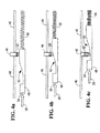
- the detent 46 and detent moving mechanism 48 are best illustrated in Figs 4a to 4c , which illustrate the detent 46 and the detent moving mechanism 48 in three different positions.
- the detent 46 comprises a metal stub extending through a detent aperture (not shown) in the floor 40 and urged downwards by a coil spring 50 surrounding the metal stub.
- the detent moving mechanism 48 defines an arcuate cam surface 52 that engages with a lower surface of the detent 46, and a tine-engaging surface 54 for receiving a front end of a tine 28 as it enters one of the channels 30.
- a resilient member 56 in the form of a coil spring, is coupled between the non-picking end 20 and the detent moving mechanism 48 to urge the detent moving mechanism 48 towards the picking end 24.
- the urging plate 44, the floor 40, and the picking end 24 define a media zone 60 which can be filled with a stack 62 of media items, in this embodiment, the media items are banknotes.
- the stack 62 is oriented horizontally, with the long edges of the banknotes resting on the floor 40. The operator then replaces the lid 12.
- the detent moving mechanism 48 is urged by the tine 28 through a partially open position shown in Fig 4b to an open position shown in Fig 4c .
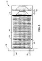
- the open position of Fig 4c corresponds to position "B" in Fig 5 .
- the urging plate 44 When the detent 46 is in the open position, the urging plate 44 may be located closer to the non-picking end 20 than when the detent 46 is in the closed position because the detent 46 has been moved beneath the floor 40, thereby allowing the urging plate 44 to move towards the non-picking end 20 if forced backwards by the stack 62 of banknotes. This can occur if the currency zone 60 was overfilled with banknotes when the cassette 10 was filled by the operator. By allowing the urging plate 44 to move backwards, the size of the currency zone 60 is increased (as shown by arrow 64 in Fig 5 ), which means that less force is applied to a banknote located at the pick window 22. This allows the currency dispenser 58 to execute a more reliable pick operation, thereby reducing the number of failed pick operations.
- the cassette 100 has a lid 112 secured to a body 114 by a latch 116.
- the body 114 has a handle 118 at a handle end 120 (a "non-picking end"), and a closed pick window 122 at the opposite end 124 (a "picking end").
- the picking end 124 includes a roller shutter 126 covering the pick window 122 when the currency cassette 100 is being transported.
- the cassette 100 includes a floor 140, beneath which a central rail 142 is provided that extends longitudinally along the cassette 100 from the non-picking end 120 to the picking end 124.
- a biased urging plate 144 is mounted on the central rail 142 and coupled thereto by a ratchet mechanism (not shown). The urging plate 144 urges a stack of banknotes towards the pick window 122, so that when the pick window 122 is open, banknotes can be picked through the pick window 122 by the currency dispenser.
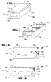
- a detent moving mechanism 174 is defined by an underside of the lid 112 and arranged to engage with the detent 170, and urge the detent 170 downwards as the lid 112 is placed on the body 114 to close the cassette 100.
- the detent 170 When the lid 112 is removed from the body 114, then the detent 170 is urged upwards by spring 172 into contact with the urging plate 144 to maintain the urging plate in a first position (shown as position "A" in broken lines in Fig 9 ) in close engagement with a horizontal stack of banknotes. In the event that the cassette is empty or nearly empty, then the detent 170 will ensure that the urging plate 144 is not moved beyond the first position towards the non-picking end 120.
- the detent 170 includes a hook end 180 that is guided by a guide surface 182 on the urging plate 144 into an engaged position.
- the hook end 180 engages with both a forward stopping surface 184 to prevent the urging plate 144 from moving beyond the first position towards the non-picking end 120, and also with a rear stopping surface 186 to prevent the urging plate 144 from moving towards the picking end 124.
- This arrangement obviates the need for a conventional latch (typically located in the floor of the currency cassette).
- the detent 46 may be located entirely beneath the floor 40 and may abut a surface of the urging plate 44 beneath the floor 40.
- media items other than banknotes may be used, for example, tickets, passes, stamps, or the like.
- the detent moving mechanism may be implemented by a solenoid.
- the solenoid may be triggered by a signal received from a media handler, such as a currency cassette.
- the signal may be transmitted wirelessly or by physical contact, or in any other convenient manner.
- the signal may be transmitted by radio-frequency, a magnetic field, or in any convenient manner.
- a plurality of detents may be provided transverse to the central rail, and the detent moving mechanism may be activated by two tines, one at each side of the cassette. This allows both conventional tines on an automated teller machine currency dispenser to be used to move the (or multiple) detent moving mechanism(s).
Landscapes
- Physics & Mathematics (AREA)
- General Physics & Mathematics (AREA)
- Sheets, Magazines, And Separation Thereof (AREA)
- Feeding And Guiding Record Carriers (AREA)
- Pile Receivers (AREA)
Abstract
Description
- The present invention relates to a media cassette.
- Media cassettes are used to store media in sheet form for automated picking and dispensing in a self-service terminal (SST). One particular type of media cassette is a currency cassette, which is used in an automated teller machine (ATM). Currency cassettes are sometimes overfilled by bullion centre or cash-in-transit personnel or machines. When a currency cassette is overfilled then an ATM in which the cassette is installed may not be able to pick banknotes reliably from that cassette because of excessive pressure on the banknote nearest a pick window. This can cause the ATM to go out of service, which results in increased cost and poorer performance for the ATM.
- Accordingly, the invention generally provides methods, systems, and apparatus for an improved media cassette.
- According to a first aspect there is provided a media cassette including a body coupled to a removable lid, the media cassette comprising a housing defining a closeable pick window; an urging plate biased towards the pick window for urging a stack of media items towards the pick window; a detent located distal from the pick window for limiting movement of the urging plate; and a detent moving mechanism operable to move the detent when the lid is closed, thereby allowing the urging plate to exert less force on the stack of media items.
- The detent may be moved by closing the removable lid. For example, the detent moving mechanism may be mounted on the removable lid, so that closing the removable lid causes the detent moving mechanism to engage with and move the detent.
- Alternatively, the detent may be moved by inserting the media cassette into a media dispenser, so that the action of closing the removable lid does not move the detent, but the detent is only moved after (in some circumstances a substantial time after) the removable lid has been closed. However, a media cassette is only inserted into a media handler with the removable lid closed, so the detent moving mechanism moves the detent only when the lid is closed.
- The urging plate may be slideably mounted on a floor spaced from a lower side of the housing, and coupled to a central rail located beneath the floor. The urging plate may be coupled to a spring that biases the urging plate towards the pick window. The floor, a pick window end of the cassette, and the urging plate may cooperate to define a media zone in which a stack of media items are placed. The media zone may be a currency zone, and the media items may be banknotes resting on their respective long edges, that is, the stack may be a horizontal stack rather than a vertical stack.
- Optionally, the detent may be implemented by a member protruding above the floor and moveable from a first position to a second position. Optionally, the detent may be implemented by a member located beneath the floor for engaging a lower part of the urging plate, and moveable from a first position to a second position. Optionally, the detent may be implemented by an upwardly-biased member coupled to a housing wall opposite the pick window.
- The member protruding above the floor may be implemented by a resiliently-biased stub protruding through a detent aperture in the floor, with the bias acting to push the stub towards the lower side of the housing. In this arrangement, the first and second positions are located in vertical alignment (that is, vertical movement of the member shifts the member between the first and the second positions).
- The detent moving mechanism may be implemented by a cam member resiliently coupled to an end of the housing, and including a cam surface. The cam member may be moveable from an inactive position to an active position. When in the inactive position, the cam surface causes the resiliently-biased stub to protrude through the detent aperture and above the floor (the first position), thereby stopping the urging plate from moving beyond the detent to an end opposite the pick window (the "non-picking end"). In contrast, when in the active position, the cam surface allows the resiliently-biased stub to extend beneath the floor (the second position), thereby allowing the urging plate to move beyond the location of the detent towards the non-picking end.
- Alternatively, the detent moving mechanism may be implemented by a stub located on the removable lid, so that when the removable lid is closed, the stub presses downwards on the upwardly-biased member, thereby allowing the urging plate to move towards the housing wall opposite the pick window.
- The cam member may be moved from the inactive position to the active position by tines located within the ATM and provided to open the pick window as the cassette is mounted in the ATM.
- Alternatively, the member protruding above the floor may be implemented by a block slideably moveable parallel to the central rail, so that both the first and second positions are located in a plane parallel to the central rail, but the second position is closer to the non-picking end than the first position. In this arrangement the first and second positions are located in horizontal alignment (that is, horizontal movement of the block shifts the block between the first and the second positions).
- The detent moving mechanism may be implemented in a plurality of different ways. For example, tines located within the ATM and provided to open the pick window as the cassette is mounted in the ATM may be used to move the block from the first position to the second position. As another example, a solenoid may be provided to drive the block from the first position to the second position when the cassette is inserted into the ATM, and to drive the block back to the first position when the block is removed from the ATM. The power supply for the solenoid may be internal to the cassette (for example, a battery) or received externally, for example, from the ATM.
- Other detent moving mechanisms for moving the detent from the first position to the second position are possible, for example, using rotary, arcuate, or elliptical movement to move the detent.
- By virtue of this aspect, when a media cassette is loaded into a self-service terminal, the pick window is opened, and the urging plate is allowed to move backwards relative to the pick window, thereby enlarging the media zone and ensuring that excessive force is not applied to the media items, even if the cassette has been overfilled.
- According to a second aspect there is provided a method of presenting media within a media cassette comprising a body closed by a removable lid, the body having a pick window defined by one end of the cassette and a non-picking end opposite the pick window, the method comprising: urging a stack of media items towards the pick window; moving a detent from (i) a first position limiting movement of an urging plate when the removable lid is open, to (ii) a second position when the removable lid is closed, the second position allowing the urging plate to move further from the pick window than when the detent is in the first position; thereby allowing more space for the media between the pick window and the urging plate.
- The step of moving a detent from a first position to a second position may comprise moving the detent vertically.
- Alternatively, or additionally, the step of moving a detent from a first position to a second position may comprise moving the detent horizontally.
- The step of moving a detent from a first position to a second position may be implemented by closing the removable lid. Alternatively, the step of moving the detent from the first position to the second position may be implemented subsequent to closing the removable lid, for example, by inserting the media cassette into a media dispenser.
- According to a third aspect there is provided a media cassette comprising a housing defining a closeable pick window; an urging plate biased towards the pick window for urging a stack of media items towards the pick window; a detent located distal from the pick window for limiting movement of the urging plate when the pick window is closed; and a detent moving mechanism operable to move the detent when the pick window is opened, thereby allowing the urging plate to exert less force on the stack of media items.
- According to a fourth aspect there is provided a self-service terminal comprising a dispenser including a pick unit engaged with a media cassette of the first or third aspect.
- The pick unit may include a plurality of tines for engaging with the media cassette to open the pick window and to move the detent from the first position to the second position.
- The self-service terminal may be an automated teller machine (ATM), an information kiosk, a financial services centre, a bill payment kiosk, a lottery kiosk, a postal services machine, a check-in and/or check-out terminal such as those used in the retail, hotel, car rental, gaming, healthcare, and airline industries, and the like.
- These and other aspects will be apparent from the following specific description, given by way of example, with reference to the accompanying drawings, in which:
-
Fig 1 is a schematic perspective diagram of a media cassette in the form of a currency cassette according to one embodiment of the present invention; -
Fig 2 is a schematic diagram of a body portion of the currency cassette ofFig 1 shown with a lid removed; -
Fig 3 is a simplified sectional side view of the body portion of the cassette ofFig 1 illustrating a detent mechanism; -
Figs 4a to 4c are simplified side views showing the detent mechanism ofFig 3 in more detail; -
Fig 5 is a plan view of the body portion of the currency cassette ofFig 2 being inserted into a media dispenser, illustrating the detent mechanism in two positions; -
Fig 6 is a schematic perspective diagram of a media cassette in the form of a currency cassette according to another embodiment of the present invention; -
Fig 7 is a schematic diagram of a body portion of the currency cassette ofFig 6 shown with a lid removed; -
Fig 8 is a simplified sectional side view of the cassette ofFig 6 with the lid removed from the body portion of the cassette and illustrating a detent mechanism in an engaged position; -
Fig 9 is a simplified sectional side view of the cassette ofFig 6 with the lid coupled to the body portion of the cassette and illustrating the detent mechanism in a disengaged position; and -
Fig 10 is a simplified sectional side view of a part of the media cassette ofFig 6 illustrating the detent mechanism and an urging plate in more detail. - Reference is first made to
Figs 1 to 3 , which illustrate amedia cassette 10 in the form of a polycarbonate currency cassette for storing banknotes. Thecassette 10 has alid 12 secured to abody 14 by alatch 16. Thebody 14 has ahandle 18 at a handle end 20 (a "non-picking end"), and a closedpick window 22 at the opposite end 24 (a "picking end"). - The picking
end 24 includes aroller shutter 26 covering thepick window 22 when thecurrency cassette 10 is being transported. As is known in the art, when a currency cassette is inserted into a currency dispenser (not shown) in an ATM (not shown), tines 28 in the currency dispenser engage with blocks (not shown) mounted inchannels 30 defined by thebody 14 to raise theroller shutter 26 and open thepick window 22. - The
cassette 10 includes afloor 40, beneath which acentral rail 42 is provided that extends longitudinally along thecassette 10 from thenon-picking end 20 to the pickingend 24. Abiased urging plate 44 is mounted on thecentral rail 42 and coupled thereto by a ratchet mechanism (not shown). Theurging plate 44 urges a stack of banknotes towards thepick window 22, so that when thepick window 22 is open, banknotes can be picked through thepick window 22 by the currency dispenser. - The features described up to this point are known from conventional currency cassettes. In addition to these known features, a detent 46 is located distal from the
pick window 22 for limiting movement of theurging plate 44 when thepick window 22 is closed. Adetent moving mechanism 48 is located within one of thechannels 30 and is operative to move thedetent 46 on insertion and removal of thecurrency cassette 10 from a currency dispenser. - The
detent 46 anddetent moving mechanism 48 are best illustrated inFigs 4a to 4c , which illustrate thedetent 46 and thedetent moving mechanism 48 in three different positions. Thedetent 46 comprises a metal stub extending through a detent aperture (not shown) in thefloor 40 and urged downwards by acoil spring 50 surrounding the metal stub. Thedetent moving mechanism 48 defines anarcuate cam surface 52 that engages with a lower surface of thedetent 46, and a tine-engagingsurface 54 for receiving a front end of atine 28 as it enters one of thechannels 30. Aresilient member 56, in the form of a coil spring, is coupled between thenon-picking end 20 and thedetent moving mechanism 48 to urge thedetent moving mechanism 48 towards the pickingend 24. - When the
currency cassette 10 is not mounted in a currency dispenser, then thedetent moving mechanism 48 is urged byspring 56 to the position shown inFig 4a , which moves thedetent 46 to a closed position. In this closed position, thedetent 46 is urged upwards through thefloor 40 by thearcuate cam surface 52, thereby preventing the urgingplate 44 from moving closer to thenon-picking end 20 than the detent location. This is illustrated inFig 5 , which is a plan view of a full currency cassette being mounted in acurrency dispenser 58. The closed position ofFig 4a corresponds to position "A" inFig 5 . - When the
cassette 10 is to be filled with currency, then an operator (whether machine or human) removes thelid 12 and retracts the urgingplate 44 until the urgingplate 44 abuts thedetent 46. The urgingplate 44 cannot be retracted any further because thedetent 46 prevents the urgingplate 44 from moving any closer to thenon-picking end 20. The urgingplate 44, thefloor 40, and the pickingend 24 define amedia zone 60 which can be filled with astack 62 of media items, in this embodiment, the media items are banknotes. Thestack 62 is oriented horizontally, with the long edges of the banknotes resting on thefloor 40. The operator then replaces thelid 12. - When the
currency cassette 10 is mounted in acurrency dispenser 58, then thedetent moving mechanism 48 is urged by thetine 28 through a partially open position shown inFig 4b to an open position shown inFig 4c . The open position ofFig 4c corresponds to position "B" inFig 5 . - When the
detent 46 is in the open position, the urgingplate 44 may be located closer to thenon-picking end 20 than when thedetent 46 is in the closed position because thedetent 46 has been moved beneath thefloor 40, thereby allowing the urgingplate 44 to move towards thenon-picking end 20 if forced backwards by thestack 62 of banknotes. This can occur if thecurrency zone 60 was overfilled with banknotes when thecassette 10 was filled by the operator. By allowing the urgingplate 44 to move backwards, the size of thecurrency zone 60 is increased (as shown byarrow 64 inFig 5 ), which means that less force is applied to a banknote located at thepick window 22. This allows thecurrency dispenser 58 to execute a more reliable pick operation, thereby reducing the number of failed pick operations. - When the
currency cassette 10 is removed from thecurrency dispenser 58, then thedetent moving mechanism 48 is urged byspring 56 back to the position shown inFig 4a so that thedetent 46 is in the closed position. - Another embodiment of the present invention will now be described with reference to
Figs 6 to 9 , which illustrate acurrency cassette 100 with a detent moving mechanism mounted in a lid of thecurrency cassette 100. - The
cassette 100 has alid 112 secured to abody 114 by alatch 116. Thebody 114 has ahandle 118 at a handle end 120 (a "non-picking end"), and aclosed pick window 122 at the opposite end 124 (a "picking end"). - The picking
end 124 includes aroller shutter 126 covering thepick window 122 when thecurrency cassette 100 is being transported. - The
cassette 100 includes afloor 140, beneath which acentral rail 142 is provided that extends longitudinally along thecassette 100 from thenon-picking end 120 to the pickingend 124. Abiased urging plate 144 is mounted on thecentral rail 142 and coupled thereto by a ratchet mechanism (not shown). The urgingplate 144 urges a stack of banknotes towards thepick window 122, so that when thepick window 122 is open, banknotes can be picked through thepick window 122 by the currency dispenser. - A
detent 170 is coupled to the handle end (the non-picking end) 120 and is biased upwards (towards the lid 112) by aspring 172. Thedetent 170 prevents the urgingplate 144 from moving too close to thehandle end 120. - A
detent moving mechanism 174 is defined by an underside of thelid 112 and arranged to engage with thedetent 170, and urge thedetent 170 downwards as thelid 112 is placed on thebody 114 to close thecassette 100. - When the
lid 112 is removed from thebody 114, then thedetent 170 is urged upwards byspring 172 into contact with the urgingplate 144 to maintain the urging plate in a first position (shown as position "A" in broken lines inFig 9 ) in close engagement with a horizontal stack of banknotes. In the event that the cassette is empty or nearly empty, then thedetent 170 will ensure that the urgingplate 144 is not moved beyond the first position towards thenon-picking end 120. - When the
lid 112 is coupled to thebody 114, then thedetent 170 is urged downwards bydetent moving mechanism 174. This allows the urgingplate 144 to be moved to a second position (shown as position "B" inFig 9 ) towards thenon-picking end 120. If too many banknotes have been loaded into thecassette 100, then the pressure of the banknotes on the urgingplate 144 will cause the urgingplate 144 to move to, or towards, the second position ("B"). - As illustrated in
Fig 10 , thedetent 170 includes ahook end 180 that is guided by aguide surface 182 on the urgingplate 144 into an engaged position. In the engaged position, thehook end 180 engages with both a forward stoppingsurface 184 to prevent the urgingplate 144 from moving beyond the first position towards thenon-picking end 120, and also with arear stopping surface 186 to prevent the urgingplate 144 from moving towards the pickingend 124. This arrangement obviates the need for a conventional latch (typically located in the floor of the currency cassette). - Various modifications may be made to the above described embodiment within the scope of the invention, for example, in other embodiments the
detent 46 may be located entirely beneath thefloor 40 and may abut a surface of the urgingplate 44 beneath thefloor 40. - In other embodiments, media items other than banknotes may be used, for example, tickets, passes, stamps, or the like.
- In other embodiments, the detent moving mechanism may be implemented by a solenoid. The solenoid may be triggered by a signal received from a media handler, such as a currency cassette. The signal may be transmitted wirelessly or by physical contact, or in any other convenient manner. The signal may be transmitted by radio-frequency, a magnetic field, or in any convenient manner.
- In other embodiments, the detent moving mechanism may move the detent horizontally rather than vertically. For example, the detent may be moveable parallel to the central rail.
- In other embodiments, a plurality of detents may be provided transverse to the central rail, and the detent moving mechanism may be activated by two tines, one at each side of the cassette. This allows both conventional tines on an automated teller machine currency dispenser to be used to move the (or multiple) detent moving mechanism(s).
- The steps of the methods described herein may be carried out in any suitable order, or simultaneously where appropriate.
- The terms "comprising", "including", "incorporating", and "having" are used herein to recite an open-ended list of one or more elements or steps, not a closed list. When such terms are used, those elements or steps recited in the list are not exclusive of other elements or steps that may be added to the list.
Claims (15)
- A media cassette (10,100) comprising:a body (14,114) coupled to a removable lid (12,112), the body (14) defining a closeable pick window (22,122);an urging plate (44,144) biased towards the pick window (22,122) for urging a stack (62) of media items towards the pick window (22,122);a detent (46,170) located distal from the pick window (22,122) for limiting movement of the urging plate (44); anda detent moving mechanism (48,174) operable to move the detent (46,170) when the lid (12,112) is closed, thereby allowing the urging plate (44,144) to exert less force on the stack (62) of media items.
- A media cassette according to claim 1, wherein the urging plate (44,144) is slideably mounted on a floor (40,140) spaced from a lower side of the body (14,114), and coupled to a central rail (42,142) located beneath the floor (40,140).
- A media cassette according to claim 2, wherein the urging plate (44,144), the floor (40,140), and a pick window end (24,124) of the cassette (10,100) cooperate to define a media zone (60) in which a stack (62) of media items are placed so that the media zone (60) is enlarged when the detent moving mechanism (48,174) moves the detent (46,170) from a first position to a second position.
- A media cassette according to claim 2 or 3, wherein the detent (46) comprises a member protruding above the floor (40) and moveable from a first position to a second position.
- A media cassette according to any of claims 2 to 4, wherein the detent (46) comprises a resiliently-biased stub protruding through a detent aperture in the floor (40).
- A media cassette according to any of claims 1 to 3, wherein the detent (170) comprises an upwardly-biased member coupled to a body wall (120) opposite the pick window (122).
- A media cassette according to claim 6, wherein the removable lid (112) includes a detent moving mechanism (174).
- A media cassette according to any of claims 2 to 5, wherein the detent moving mechanism (48) comprises a cam member resiliently coupled to an end of the housing, and including a cam surface (52), the cam member being moveable from (i) an inactive position in which the cam surface (52) causes the resiliently-biased stub to protrude through the detent aperture and above the floor (40) thereby stopping the urging plate (44) from moving beyond the detent (46) to an end (20) opposite the pick window (22), to (ii) an active position in which the cam surface (52) allows the resiliently-biased stub to extend beneath the floor (40) thereby allowing the urging plate (44) to move beyond the location of the detent (46) to an end (20) opposite the pick window (22).
- A media cassette according to claim 8, wherein the cam member is moved from the inactive position to the active position by tines (28) located within a currency dispenser (58) in an ATM, where the tines (28) also open the pick window (22) as the cassette (10) is inserted into the currency dispenser (58).
- A media cassette according to any of claims 1 to 5, 8 or 9, wherein the detent (46) comprises a member located beneath the floor (40) for engaging a lower part of the urging plate (44), and moveable from a first position to a second position.
- A media cassette according to claim 4, wherein the member protruding above the floor (40) comprises a block slideably moveable parallel to the central rail (42), so that both the first and second positions are located above the floor (40), but the second position is closer to the end (20) opposite the pick window (22) than the first position.
- A method of presenting media within a media cassette (10,100) comprising a body (14,114) closed by a removable lid (12,112), the body (14,114) having a pick window (22,122) defined by one end (24,124) of the cassette (10,100) and a non-picking end (20,120) opposite the pick window (22,122), the method comprising:urging a stack of media items towards the pick window (22,122);moving a detent (46,170) from (i) a first position when the removable lid (12,112) is open, the first position limiting movement of an urging plate (44,144), to (ii) a second position when the removable lid (12,112) is closed, the second position allowing the urging plate (44,144) to move further from the pick window (22,122) than when the detent (46,170) is in the first position;thereby allowing more space for the stack of media items between the pick window (22,122) and the urging plate (44,144).
- A method according to claim 12, wherein the step of moving the detent (46) from the first position to the second position is implemented subsequent to closing the removable lid (12) on insertion of the media cassette (10) into a media dispenser (58).
- A self-service terminal comprising a dispenser including a pick unit engaged with a media cassette (10) according to any of claims 1 to 11.
- A self-service terminal according to claim 14, wherein the pick unit includes a plurality of tines (28) for engaging with the media cassette (10) to open the pick window (22) and to move the detent (46) from a first position to a second position.
Applications Claiming Priority (1)
| Application Number | Priority Date | Filing Date | Title |
|---|---|---|---|
| US12/338,262 US8196920B2 (en) | 2008-12-18 | 2008-12-18 | Media cassette |
Publications (3)
| Publication Number | Publication Date |
|---|---|
| EP2199989A2 true EP2199989A2 (en) | 2010-06-23 |
| EP2199989A3 EP2199989A3 (en) | 2010-08-04 |
| EP2199989B1 EP2199989B1 (en) | 2012-10-24 |
Family
ID=41050496
Family Applications (1)
| Application Number | Title | Priority Date | Filing Date |
|---|---|---|---|
| EP09164348A Active EP2199989B1 (en) | 2008-12-18 | 2009-07-01 | Media cassette |
Country Status (3)
| Country | Link |
|---|---|
| US (1) | US8196920B2 (en) |
| EP (1) | EP2199989B1 (en) |
| ES (1) | ES2397753T3 (en) |
Families Citing this family (3)
| Publication number | Priority date | Publication date | Assignee | Title |
|---|---|---|---|---|
| US8668194B2 (en) | 2011-07-29 | 2014-03-11 | Ncr Corporation | Media cassette |
| CN110288758B (en) * | 2018-03-13 | 2021-05-25 | 山东新北洋信息技术股份有限公司 | Cash box and cash recycling equipment |
| US11328563B1 (en) * | 2021-04-23 | 2022-05-10 | Ncr Corporaton | Apparatus, system, and method for bulk currency note deposits |
Family Cites Families (14)
| Publication number | Priority date | Publication date | Assignee | Title |
|---|---|---|---|---|
| SE429693B (en) * | 1978-12-08 | 1983-09-19 | De La Rue Syst | SEKERHETSKASSETT |
| JPS5598036A (en) * | 1979-01-20 | 1980-07-25 | Omron Tateisi Electronics Co | Sheet delivery cassette device |
| US4280692A (en) * | 1980-02-21 | 1981-07-28 | Nashua Corporation | Cassette with lockable lift plate |
| JPS59207336A (en) * | 1983-05-11 | 1984-11-24 | Hitachi Ltd | Banknote storing box in cash dispenser |
| US4593895A (en) * | 1984-04-06 | 1986-06-10 | Ncr Corporation | Automatically adjusting currency pusher plate apparatus |
| DE3434780A1 (en) * | 1984-09-21 | 1986-03-27 | Nixdorf Computer Ag, 4790 Paderborn | SHEET DRAWER WITH AN INSERT CASSETTE FOR RECEIVING A STACK OF SHEETS |
| US4659008A (en) * | 1985-04-12 | 1987-04-21 | Ncr Corporation | Tampering-proof cassette used in a cash dispenser |
| CA1310502C (en) * | 1986-10-08 | 1992-11-24 | De La Rue Systems Limited | Sheet store |
| JP2568130B2 (en) * | 1990-03-27 | 1996-12-25 | 富士通機電株式会社 | Cassette blocking mechanism |
| DE4200186C1 (en) * | 1992-01-07 | 1993-07-15 | Siemens Nixdorf Informationssysteme Ag, 4790 Paderborn, De | |
| US5379997A (en) * | 1992-03-31 | 1995-01-10 | Fuji Photo Film Co., Ltd. | Cassette |
| KR100746920B1 (en) * | 2001-12-13 | 2007-08-08 | 엘지엔시스(주) | Cash dispenser prevention device of cash dispenser |
| KR100627557B1 (en) * | 2004-12-24 | 2006-09-21 | 노틸러스효성 주식회사 | Banknote Machine Cassette |
| US7497436B2 (en) * | 2005-12-16 | 2009-03-03 | Ncr Corporation | Media cassette pusher plate locking mechanism |
-
2008
- 2008-12-18 US US12/338,262 patent/US8196920B2/en active Active
-
2009
- 2009-07-01 ES ES09164348T patent/ES2397753T3/en active Active
- 2009-07-01 EP EP09164348A patent/EP2199989B1/en active Active
Also Published As
| Publication number | Publication date |
|---|---|
| EP2199989A3 (en) | 2010-08-04 |
| ES2397753T3 (en) | 2013-03-11 |
| EP2199989B1 (en) | 2012-10-24 |
| US8196920B2 (en) | 2012-06-12 |
| US20100156034A1 (en) | 2010-06-24 |
Similar Documents
| Publication | Publication Date | Title |
|---|---|---|
| JP6438642B2 (en) | Paper sheet handling equipment | |
| US20100200448A1 (en) | Currency storage cassette and currency handling apparatus | |
| JP5919953B2 (en) | Drawer and medium transaction device | |
| US20090260948A1 (en) | Money handling machine | |
| PL198179B1 (en) | A device for automatically conducting banking operations and a way for automatically conducting banking operations | |
| JP4979436B2 (en) | Paper sheet processing equipment | |
| US8245830B2 (en) | Paper currency handling device | |
| US7472781B2 (en) | Bill handling device and control system thereof | |
| EP3308364B1 (en) | Core module for an automated transaction machine | |
| EP2199989B1 (en) | Media cassette | |
| US8262083B2 (en) | Media cassette | |
| EP2146331A1 (en) | Paper money processor | |
| CN104919503A (en) | Extraction device and medium transaction device | |
| JP5831010B2 (en) | Lock device and automatic cash transaction device | |
| JP6102487B2 (en) | Medium storage apparatus and medium transaction apparatus | |
| KR101016245B1 (en) | Withdrawal device of automatic teller machine | |
| JP4997459B2 (en) | Banknote collection cassette, banknote collection mechanism, and reflux-type banknote processing apparatus | |
| JP6413389B2 (en) | Media processing device | |
| JP2015088138A (en) | Paper sheet handling equipment | |
| JP7226098B2 (en) | Media processing device and media trading device | |
| JP2020060940A (en) | Currency processing device and currency processing system | |
| KR101942545B1 (en) | Medium cassette, medium process apparatus and financial device | |
| JP2026067231A (en) | Coin processing device and automated transaction device | |
| JP4768293B2 (en) | Paper sheet storage device | |
| JP6206170B2 (en) | Small bundle processing equipment |
Legal Events
| Date | Code | Title | Description |
|---|---|---|---|
| PUAI | Public reference made under article 153(3) epc to a published international application that has entered the european phase |
Free format text: ORIGINAL CODE: 0009012 |
|
| 17P | Request for examination filed |
Effective date: 20090701 |
|
| AK | Designated contracting states |
Kind code of ref document: A2 Designated state(s): AT BE BG CH CY CZ DE DK EE ES FI FR GB GR HR HU IE IS IT LI LT LU LV MC MK MT NL NO PL PT RO SE SI SK SM TR |
|
| AX | Request for extension of the european patent |
Extension state: AL BA RS |
|
| PUAL | Search report despatched |
Free format text: ORIGINAL CODE: 0009013 |
|
| AK | Designated contracting states |
Kind code of ref document: A3 Designated state(s): AT BE BG CH CY CZ DE DK EE ES FI FR GB GR HR HU IE IS IT LI LT LU LV MC MK MT NL NO PL PT RO SE SI SK SM TR |
|
| AX | Request for extension of the european patent |
Extension state: AL BA RS |
|
| GRAP | Despatch of communication of intention to grant a patent |
Free format text: ORIGINAL CODE: EPIDOSNIGR1 |
|
| GRAS | Grant fee paid |
Free format text: ORIGINAL CODE: EPIDOSNIGR3 |
|
| GRAA | (expected) grant |
Free format text: ORIGINAL CODE: 0009210 |
|
| AK | Designated contracting states |
Kind code of ref document: B1 Designated state(s): AT BE BG CH CY CZ DE DK EE ES FI FR GB GR HR HU IE IS IT LI LT LU LV MC MK MT NL NO PL PT RO SE SI SK SM TR |
|
| REG | Reference to a national code |
Ref country code: GB Ref legal event code: FG4D |
|
| REG | Reference to a national code |
Ref country code: CH Ref legal event code: EP |
|
| REG | Reference to a national code |
Ref country code: AT Ref legal event code: REF Ref document number: 581280 Country of ref document: AT Kind code of ref document: T Effective date: 20121115 |
|
| REG | Reference to a national code |
Ref country code: IE Ref legal event code: FG4D |
|
| REG | Reference to a national code |
Ref country code: GB Ref legal event code: 746 Effective date: 20121119 |
|
| REG | Reference to a national code |
Ref country code: DE Ref legal event code: R096 Ref document number: 602009010588 Country of ref document: DE Effective date: 20121227 |
|
| REG | Reference to a national code |
Ref country code: DE Ref legal event code: R084 Ref document number: 602009010588 Country of ref document: DE Effective date: 20121031 |
|
| REG | Reference to a national code |
Ref country code: ES Ref legal event code: FG2A Ref document number: 2397753 Country of ref document: ES Kind code of ref document: T3 Effective date: 20130311 |
|
| REG | Reference to a national code |
Ref country code: AT Ref legal event code: MK05 Ref document number: 581280 Country of ref document: AT Kind code of ref document: T Effective date: 20121024 |
|
| REG | Reference to a national code |
Ref country code: NL Ref legal event code: VDEP Effective date: 20121024 |
|
| PG25 | Lapsed in a contracting state [announced via postgrant information from national office to epo] |
Ref country code: FI Free format text: LAPSE BECAUSE OF FAILURE TO SUBMIT A TRANSLATION OF THE DESCRIPTION OR TO PAY THE FEE WITHIN THE PRESCRIBED TIME-LIMIT Effective date: 20121024 Ref country code: NL Free format text: LAPSE BECAUSE OF FAILURE TO SUBMIT A TRANSLATION OF THE DESCRIPTION OR TO PAY THE FEE WITHIN THE PRESCRIBED TIME-LIMIT Effective date: 20121024 Ref country code: HR Free format text: LAPSE BECAUSE OF FAILURE TO SUBMIT A TRANSLATION OF THE DESCRIPTION OR TO PAY THE FEE WITHIN THE PRESCRIBED TIME-LIMIT Effective date: 20121024 Ref country code: NO Free format text: LAPSE BECAUSE OF FAILURE TO SUBMIT A TRANSLATION OF THE DESCRIPTION OR TO PAY THE FEE WITHIN THE PRESCRIBED TIME-LIMIT Effective date: 20130124 Ref country code: IS Free format text: LAPSE BECAUSE OF FAILURE TO SUBMIT A TRANSLATION OF THE DESCRIPTION OR TO PAY THE FEE WITHIN THE PRESCRIBED TIME-LIMIT Effective date: 20130224 Ref country code: SE Free format text: LAPSE BECAUSE OF FAILURE TO SUBMIT A TRANSLATION OF THE DESCRIPTION OR TO PAY THE FEE WITHIN THE PRESCRIBED TIME-LIMIT Effective date: 20121024 |
|
| REG | Reference to a national code |
Ref country code: ES Ref legal event code: GC2A Effective date: 20130506 |
|
| PG25 | Lapsed in a contracting state [announced via postgrant information from national office to epo] |
Ref country code: SI Free format text: LAPSE BECAUSE OF FAILURE TO SUBMIT A TRANSLATION OF THE DESCRIPTION OR TO PAY THE FEE WITHIN THE PRESCRIBED TIME-LIMIT Effective date: 20121024 Ref country code: GR Free format text: LAPSE BECAUSE OF FAILURE TO SUBMIT A TRANSLATION OF THE DESCRIPTION OR TO PAY THE FEE WITHIN THE PRESCRIBED TIME-LIMIT Effective date: 20130125 Ref country code: PT Free format text: LAPSE BECAUSE OF FAILURE TO SUBMIT A TRANSLATION OF THE DESCRIPTION OR TO PAY THE FEE WITHIN THE PRESCRIBED TIME-LIMIT Effective date: 20130225 Ref country code: LV Free format text: LAPSE BECAUSE OF FAILURE TO SUBMIT A TRANSLATION OF THE DESCRIPTION OR TO PAY THE FEE WITHIN THE PRESCRIBED TIME-LIMIT Effective date: 20121024 Ref country code: BE Free format text: LAPSE BECAUSE OF FAILURE TO SUBMIT A TRANSLATION OF THE DESCRIPTION OR TO PAY THE FEE WITHIN THE PRESCRIBED TIME-LIMIT Effective date: 20121024 Ref country code: PL Free format text: LAPSE BECAUSE OF FAILURE TO SUBMIT A TRANSLATION OF THE DESCRIPTION OR TO PAY THE FEE WITHIN THE PRESCRIBED TIME-LIMIT Effective date: 20121024 |
|
| PG25 | Lapsed in a contracting state [announced via postgrant information from national office to epo] |
Ref country code: AT Free format text: LAPSE BECAUSE OF FAILURE TO SUBMIT A TRANSLATION OF THE DESCRIPTION OR TO PAY THE FEE WITHIN THE PRESCRIBED TIME-LIMIT Effective date: 20121024 |
|
| PG25 | Lapsed in a contracting state [announced via postgrant information from national office to epo] |
Ref country code: EE Free format text: LAPSE BECAUSE OF FAILURE TO SUBMIT A TRANSLATION OF THE DESCRIPTION OR TO PAY THE FEE WITHIN THE PRESCRIBED TIME-LIMIT Effective date: 20121024 Ref country code: DK Free format text: LAPSE BECAUSE OF FAILURE TO SUBMIT A TRANSLATION OF THE DESCRIPTION OR TO PAY THE FEE WITHIN THE PRESCRIBED TIME-LIMIT Effective date: 20121024 Ref country code: BG Free format text: LAPSE BECAUSE OF FAILURE TO SUBMIT A TRANSLATION OF THE DESCRIPTION OR TO PAY THE FEE WITHIN THE PRESCRIBED TIME-LIMIT Effective date: 20130124 Ref country code: CZ Free format text: LAPSE BECAUSE OF FAILURE TO SUBMIT A TRANSLATION OF THE DESCRIPTION OR TO PAY THE FEE WITHIN THE PRESCRIBED TIME-LIMIT Effective date: 20121024 Ref country code: SK Free format text: LAPSE BECAUSE OF FAILURE TO SUBMIT A TRANSLATION OF THE DESCRIPTION OR TO PAY THE FEE WITHIN THE PRESCRIBED TIME-LIMIT Effective date: 20121024 |
|
| PG25 | Lapsed in a contracting state [announced via postgrant information from national office to epo] |
Ref country code: RO Free format text: LAPSE BECAUSE OF FAILURE TO SUBMIT A TRANSLATION OF THE DESCRIPTION OR TO PAY THE FEE WITHIN THE PRESCRIBED TIME-LIMIT Effective date: 20121024 Ref country code: IT Free format text: LAPSE BECAUSE OF FAILURE TO SUBMIT A TRANSLATION OF THE DESCRIPTION OR TO PAY THE FEE WITHIN THE PRESCRIBED TIME-LIMIT Effective date: 20121024 |
|
| PLBE | No opposition filed within time limit |
Free format text: ORIGINAL CODE: 0009261 |
|
| STAA | Information on the status of an ep patent application or granted ep patent |
Free format text: STATUS: NO OPPOSITION FILED WITHIN TIME LIMIT |
|
| 26N | No opposition filed |
Effective date: 20130725 |
|
| REG | Reference to a national code |
Ref country code: DE Ref legal event code: R097 Ref document number: 602009010588 Country of ref document: DE Effective date: 20130725 |
|
| PG25 | Lapsed in a contracting state [announced via postgrant information from national office to epo] |
Ref country code: CY Free format text: LAPSE BECAUSE OF FAILURE TO SUBMIT A TRANSLATION OF THE DESCRIPTION OR TO PAY THE FEE WITHIN THE PRESCRIBED TIME-LIMIT Effective date: 20121024 |
|
| PG25 | Lapsed in a contracting state [announced via postgrant information from national office to epo] |
Ref country code: MC Free format text: LAPSE BECAUSE OF FAILURE TO SUBMIT A TRANSLATION OF THE DESCRIPTION OR TO PAY THE FEE WITHIN THE PRESCRIBED TIME-LIMIT Effective date: 20121024 |
|
| REG | Reference to a national code |
Ref country code: CH Ref legal event code: PL |
|
| REG | Reference to a national code |
Ref country code: IE Ref legal event code: MM4A |
|
| PG25 | Lapsed in a contracting state [announced via postgrant information from national office to epo] |
Ref country code: LI Free format text: LAPSE BECAUSE OF NON-PAYMENT OF DUE FEES Effective date: 20130731 Ref country code: CH Free format text: LAPSE BECAUSE OF NON-PAYMENT OF DUE FEES Effective date: 20130731 |
|
| PG25 | Lapsed in a contracting state [announced via postgrant information from national office to epo] |
Ref country code: IE Free format text: LAPSE BECAUSE OF NON-PAYMENT OF DUE FEES Effective date: 20130701 Ref country code: LT Free format text: LAPSE BECAUSE OF FAILURE TO SUBMIT A TRANSLATION OF THE DESCRIPTION OR TO PAY THE FEE WITHIN THE PRESCRIBED TIME-LIMIT Effective date: 20121024 |
|
| PG25 | Lapsed in a contracting state [announced via postgrant information from national office to epo] |
Ref country code: SM Free format text: LAPSE BECAUSE OF FAILURE TO SUBMIT A TRANSLATION OF THE DESCRIPTION OR TO PAY THE FEE WITHIN THE PRESCRIBED TIME-LIMIT Effective date: 20121024 |
|
| PG25 | Lapsed in a contracting state [announced via postgrant information from national office to epo] |
Ref country code: MT Free format text: LAPSE BECAUSE OF FAILURE TO SUBMIT A TRANSLATION OF THE DESCRIPTION OR TO PAY THE FEE WITHIN THE PRESCRIBED TIME-LIMIT Effective date: 20121024 Ref country code: TR Free format text: LAPSE BECAUSE OF FAILURE TO SUBMIT A TRANSLATION OF THE DESCRIPTION OR TO PAY THE FEE WITHIN THE PRESCRIBED TIME-LIMIT Effective date: 20121024 |
|
| PG25 | Lapsed in a contracting state [announced via postgrant information from national office to epo] |
Ref country code: HU Free format text: LAPSE BECAUSE OF FAILURE TO SUBMIT A TRANSLATION OF THE DESCRIPTION OR TO PAY THE FEE WITHIN THE PRESCRIBED TIME-LIMIT; INVALID AB INITIO Effective date: 20090701 Ref country code: MK Free format text: LAPSE BECAUSE OF FAILURE TO SUBMIT A TRANSLATION OF THE DESCRIPTION OR TO PAY THE FEE WITHIN THE PRESCRIBED TIME-LIMIT Effective date: 20121024 Ref country code: LU Free format text: LAPSE BECAUSE OF NON-PAYMENT OF DUE FEES Effective date: 20130701 |
|
| REG | Reference to a national code |
Ref country code: FR Ref legal event code: PLFP Year of fee payment: 8 |
|
| REG | Reference to a national code |
Ref country code: FR Ref legal event code: PLFP Year of fee payment: 9 |
|
| REG | Reference to a national code |
Ref country code: FR Ref legal event code: PLFP Year of fee payment: 10 |
|
| REG | Reference to a national code |
Ref country code: DE Ref legal event code: R081 Ref document number: 602009010588 Country of ref document: DE Owner name: CARDTRONICS USA, INC. (GESELLSCHAFT NACH DEN G, US Free format text: FORMER OWNER: NCR CORPORATION, DULUTH, GA., US Ref country code: DE Ref legal event code: R082 Ref document number: 602009010588 Country of ref document: DE Representative=s name: V. BEZOLD & PARTNER PATENTANWAELTE - PARTG MBB, DE Ref country code: DE Ref legal event code: R081 Ref document number: 602009010588 Country of ref document: DE Owner name: NCR CORPORATION, ATLANTA, US Free format text: FORMER OWNER: NCR CORPORATION, DULUTH, GA., US |
|
| P01 | Opt-out of the competence of the unified patent court (upc) registered |
Effective date: 20230507 |
|
| REG | Reference to a national code |
Ref country code: DE Ref legal event code: R081 Ref document number: 602009010588 Country of ref document: DE Owner name: CARDTRONICS USA, INC. (GESELLSCHAFT NACH DEN G, US Free format text: FORMER OWNER: NCR CORPORATION, ATLANTA, GA, US |
|
| REG | Reference to a national code |
Ref country code: ES Ref legal event code: PC2A Owner name: CARDTRONICS USA, INC. Effective date: 20250728 |
|
| PGFP | Annual fee paid to national office [announced via postgrant information from national office to epo] |
Ref country code: ES Payment date: 20250801 Year of fee payment: 17 |
|
| PGFP | Annual fee paid to national office [announced via postgrant information from national office to epo] |
Ref country code: DE Payment date: 20250729 Year of fee payment: 17 |
|
| PGFP | Annual fee paid to national office [announced via postgrant information from national office to epo] |
Ref country code: GB Payment date: 20250728 Year of fee payment: 17 |
|
| PGFP | Annual fee paid to national office [announced via postgrant information from national office to epo] |
Ref country code: FR Payment date: 20250725 Year of fee payment: 17 |